Abstract
The article focuses on the design and construction of a 3D printer capable of printing both traditional cement and alkali-activated cement (AAC). Research into alkali-activated cements, commonly known as geopolymers, has progressed beyond the basic research stage, with the current challenge being the implementation of practical applications. These include solving the shaping issues of AAC paste and forming the final shape of a given product. One of the most advanced methods for achieving this is through 3D printing. The printer was created by modifying the open-source RatRig V-Core 3D printer ecosystem design to fit this purpose. Based on these modifications, an appropriate material composition was determined, and printing tests were conducted, allowing development conclusions to be drawn. A three-dimensional model of the structure was first created using Autodesk Inventor 2024 CAD software, and critical load-bearing components were validated through simulation. Special attention was given to cost-effective manufacturability, with custom parts produced using 3D printing, while additional components (e.g., bearings, fasteners) were selected from commercial catalogs. Finally, test prints using the specified material composition were performed to examine potential construction improvements for the 3D printer and assess material properties. The core concept of the cement printer lies in the material deposition method, specifically, in achieving effective extrusion of the paste. Five different versions of this were tested, which will be discussed in detail.
1. Introduction
Three-dimensional printing is one of the most significant areas of additive manufacturing technologies, enabling the creation and efficient production of complex internal structures. The printing of geopolymer-based, environmentally friendly binders is gaining increasing importance, particularly in the construction industry. The following chapter discusses these materials and the related printing technologies [1,2,3,4].
1.1. The Significance of 3D Printing and Its Position Among Manufacturing Technologies
Modern manufacturing methods can be classified into two fundamental categories: additive technologies, based on material addition, and subtractive technologies, based on material removal. Until the end of the 20th century, industrial production was predominantly built on subtractive machining. The essence of this approach lies in shaping the initial workpiece into the desired geometry through material removal, employing various machining operations such as turning, milling, or drilling. In these technologies, material removal typically occurs through cutting, where the final geometry is formed as a result of the relative motion between the tool and the workpiece. In special cases, such as electrical discharge machining, material removal takes place through electrical discharges, where the shape of the electrode is reproduced on the machined surface [5].
In contrast, additive technologies do not involve material removal. In this case, the object is produced layer by layer, meaning that the material is deposited precisely where it is required. Three-dimensional printing is one of the most well-known and fastest-developing representatives of additive manufacturing technologies [2,3,6].
Initially, 3D printing was primarily applied in rapid prototyping, since traditional techniques used in mass production, such as casting or injection molding, require extensive preparations, including tool manufacturing, which can be time-consuming and costly for a single piece or small series. In contrast, additive manufacturing enables the direct production of components from a digital model without tooling costs [7,8,9].
Another advantage is that the process does not require a diverse set of tools, unlike machining technologies, where multiple cutting tools are necessary to create the desired geometry. Three-dimensional printing offers a particularly efficient solution for producing complex shapes that are difficult or uneconomical to manufacture using conventional methods, for example, internal sharp-cornered cavities, which cannot be produced by cutting and can only be realized through electrical discharge machining. An additional benefit is that almost any shape can be created from the material processed by the printer, with the primary limitation of the technology being the size of the printing equipment [2,3,7,10].
Today, the application scope of 3D printing technologies extends far beyond prototyping. They are widely used across various industrial fields, including healthcare, for instance, in the production of customized prosthetics or small-series, specialized components [8,11]. Another example is the U.S. Army’s new silencer, which can only be manufactured using 3D printing due to its unique internal structure. In recent years, the technology has also emerged in the construction industry, where an increasing number of experiments and practical implementations involve the 3D printing of concrete and other binders [2,3,4].
1.2. General Overview of Alkali-Activated Cements
Geopolymers are alternative binders that can be produced from various raw materials available in large quantities. These base materials are accessible in many parts of the world, partly because their production does not rely solely on primary raw resources. From the perspective of suitability, several types of industrial by-products or waste materials can be utilized, such as fly ash from lignite- or coal-fired power plants, metallurgical slags, recycled glass waste, and demolition debris such as crushed brick. With appropriate activation, these materials can be rendered reactive, thereby contributing to the setting and hardening processes of geopolymers [12,13,14].
Thus, so-called alkali-activated materials belong to a group of binders whose powdered raw materials are treated with an alkaline medium, typically an alkali or salt solution, to initiate the reactions. These materials are generally capable of hardening at room temperature, and their physical and chemical properties strongly depend on the raw materials used and the type of activating medium. In certain compositions, particularly favorable mechanical characteristics can be observed, such as outstanding compressive and flexural strength [12,14,15]. It is worth noting that, according to the EN 197-1 standard [16], the highest strength class of cements reaches a compressive strength of 52.5 MPa at 28 days, which provides a useful reference point for evaluating alkali-activated systems [14,15].
1.3. Principles and Requirements of Cement and Geopolymer 3D Printing
The operating principle of cement-based 3D printers is analogous to the structure of conventional fused deposition modeling (FDM) printers. The essence of this printing technology lies in the controlled movement of the print head within a plane, which enables the layer-by-layer construction of the desired object. The process of 3D printing can be divided into four main stages: mixing, material conveying, extrusion, and subsequent building [2,17,18].
There are five fundamental criteria that must be considered in both machine design and material formulation: pumpability, extrudability, buildability (the ability of layers to bond and stack), shape retention, and open time [2,17,18,19].
1.3.1. Pumpability
The material must exhibit sufficiently high flowability in order to be pumpable, with particular consideration given to the fact that, in this case, pipelines with internal diameters of 5 mm and 10 mm are employed. The 5 mm cross-section offers the advantage of requiring relatively little material to fill the system, thus ensuring economical operation; however, difficulties may arise when conveying denser materials [2,17,18].
Two fundamental aspects must be considered when assessing pumpability: first, the avoidance of clogging, and second, the minimization of any detrimental effects on the properties of the conveyed material. Pumpability is typically evaluated based on yield stress and viscosity. For example, the ideal static yield stress after five minutes of mixing should remain below 45 kPa, as below this threshold the material will not deform. The determination of static yield stress is generally carried out using a rotational rheometer (also referred to as a viscometer). During the measurement process, the material is placed into the rheometer cup, and a rotor is rotated within it. The torque measured along the rotor axis, together with the angular velocity, allows for an assessment of the material’s flow behavior. The static yield stress corresponds to the minimum shear stress required to initiate flow and is typically measured under constant shear rates in the range of 0.01–0.5 s. It is important to note that a high-shear preconditioning phase (approximately 60 s−1) is applied prior to measurement in order to bring the samples into a reference state [2,17,18,19].
1.3.2. Extrudability
Closely related to pumpability, extrudability addresses the challenge of forcing material through the printing nozzle. Viscosity plays a critical role in determining extrudability, as geopolymers and cement pastes exhibit markedly different flow behaviors during 3D printing. The higher viscosity of cement pastes makes extrusion more difficult, requiring slower printing speeds and more precise parameter control. In addition, their slow recovery after shear loading compromises printing accuracy and stability. In contrast, geopolymers generally display lower viscosity and more favorable flow characteristics, enabling faster, more uniform extrusion and more efficient implementation [2,17,18,20].
Since the printability of geopolymers and cement-based systems is more complex than the workability of conventional cementitious materials, traditional fresh concrete tests are insufficient to describe their behavior. Currently, only a limited number of new test methods are available for assessing printability. As a result, research primarily relies on rheological measurements, evaluating parameters such as viscosity and yield stress to determine extrudability [2,17,18,20,21].
1.3.3. Buildability
Buildability refers to the ability of successive layers to bond effectively. While adequate adhesion between layers is essential, excessive flowability is undesirable, as it may cause the printed element to spread and lose its shape while buckling under the weight of successive layers [17,18,20].
1.3.4. Shape Retention
Shape retention is closely linked to buildability. This property is greatly enhanced by material compositions that include a dispersed phase, such as sand or glass powder [17,18,20,21]. Observations show that in the case of geopolymers, if the static yield stress does not exceed 100 Pa, only up to six layers can be successfully built on top of each other [2,18,21,22].
1.3.5. Open Time
During transportation and extrusion, another crucial factor is the length of the open time. This is the time interval during which the material remains processable, that is, extrudable, after mixing. Once this time elapses, the geopolymer loses its printability. Open time is typically determined by trial extrusions. If the static yield stress increases only slowly over time, the material remains workable for a longer period. After the open time has expired, the extruded geopolymer exhibits cracking and irregularity, indicating that extrusion is no longer feasible [2,17,18,21,22].
Exceeding the open time also degrades the quality of the extruded material. Within the open time window, samples show a uniform and homogeneous structure; beyond it, larger pores, surface defects, and interlayer separations appear [17,18,22,23].
1.4. Summary
In summary, the operating principle of cement- and geopolymer-based 3D printers builds upon the fundamentals of fused deposition modeling (FDM) technology, where material is deposited layer by layer. For optimal printing results, four key criteria must be carefully considered: pumpability, extrudability, buildability, and shape retention. Proper material formulation and machine design are essential to ensure printing stability and to achieve the desired quality of the final product [2,17,18,19,20,21,22,23].
In 3D concrete printing, pumpability, extrudability, and buildability impose partially conflicting rheological requirements. Low yield stress and viscosity are essential to ensure stable pumping and continuous extrusion, whereas high green strength and rapid structural build-up are required to maintain shape stability after deposition. As a result, optimizing one property often leads to the deterioration of another. This inherent contradiction makes system design and material handling strategies crucial for achieving reliable printability, particularly when complex or dispersed material systems are used [11,24,25,26].
2. The Printer Buildup
The 3D printer was designed and built with a two-level layout. The actual printing unit is located on the lower level, where the workpiece is produced. The upper section houses the unit for supplying the 3D printer with material; here, the raw material to be printed is fed in, and it is then transported to the print head using the appropriate technology. Gravity was considered in the two-level design, as it helps deliver the material to the print head, and it offers better space efficiency due to the smaller footprint. The 3D printer was divided into five main structural components:
- Machine frame
- Drives (The drives are further subdivided into subgroups.)
- Print bed
- Print head
- Feeding system
The layer-by-layer construction is made possible by the relative movement between the print bed and the nozzle of the print head, during which the nozzle covers the area where the material is intended to be deposited. The horizontal movements (along the X-Y axis) are carried out by the print head, while the vertical (Z-axis) movement is achieved by lowering and raising the print bed. Several factors were considered during the design process to enable simpler and more cost-effective construction. Recycled aluminum profiles were used in the assembly of the machine frame. The drive elements, as well as many other components, were designed to be produced using additive manufacturing technologies while ensuring that their load-bearing capacity met the required specifications. The machine frame was designed using ITEM-compatible aluminum profiles, which were iterated upon in several steps to reach their final form. I8 40 × 40 L aluminum profiles were available for the construction of the machine frame, so the design was fully adapted to these available materials. The dimensions of the machine frame components can be seen in Table 1, and are also illustrated in Figure 1.

Table 1.
The dimensions of the machine frame components.
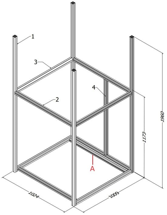
Figure 1.
Design and key dimensions of the printer frame.
The critical cross-section of the frame is located at position “A” (Figure 1), where the bending stress is maximal, as the design plan indicates that one of the three screws supporting the print bed rests exactly at the center of the given aluminum profile. As a result, the biggest deflection is expected at the “A” cross-section. A simulation of the component was created using Autodesk Inventor (Figure 2), and it was then verified whether the aluminum profile is suitable under the given conditions. For the analysis, it was assumed that the load per screw could be a maximum of 30 kg with a safety factor of two, and the length of the rod was 945 mm. The results of the simulation are shown in the figure.
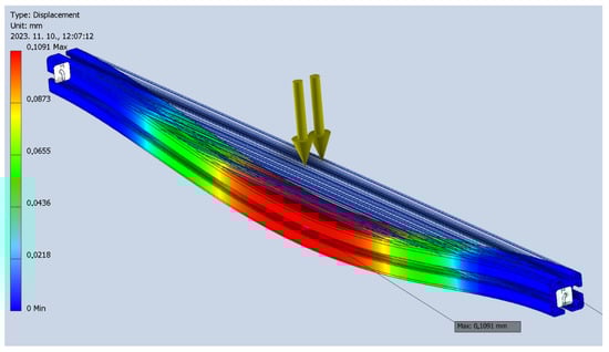
Figure 2.
Deflection analysis of the 945 mm aluminum profile under static load.
During the static load analysis, the maximum deflection was found to be only 0.1 mm, which suggests that the 40 × 40 mm ITEM aluminum profile is suitable for constructing the frame.
2.1. X-Y Axis Drives
The Core-XY drive of the structure was designed based on the Rat Rig V-Core 3 3D printer models, which are freely available on the Rat Rig website [27]. The print head is capable of moving in the X-Y plane, with the movement being carried out by two motors working in coordination. The design is based on the Core-XY kinematic drive principle, which is commonly used in commercial 3D printers of recent years. Parallel rails are installed on both sides of the printer frame, each supporting a linear carriage. These carriages are connected by a bridge. A rail is also mounted on the bridge, along which the print head, attached to the carriage, moves. The movement in the X direction is carried out by the carriage moving along the bridge, while in the Y direction, the entire bridge is shifted. The bridge is made from 20 × 20 mm BOSCH-compatible aluminum profiles (Figure 3).
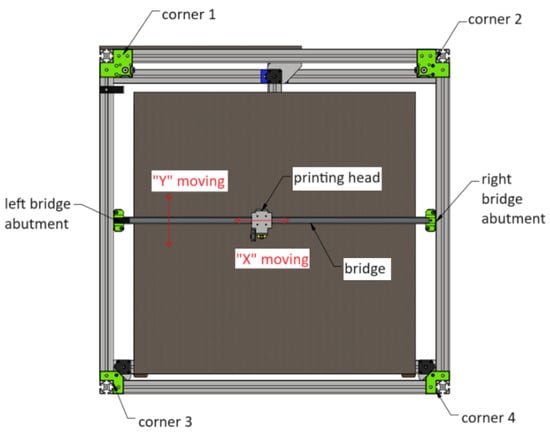
Figure 3.
Top view of the X-Y drive.
At each of the four corners of the frame, a corner drive with rollers is installed. Two of these (the 1st and 2nd corners) are equipped with motors, each of which has a toothed wheel mounted on its axis. The elements of the corner drives, as well as the bridge mounts, were created based on the Rat Rig V-Core 3 3D printer models. These models are available for free download. The Rat Rig components were originally designed for 30 mm × 30 mm BOSCH profiles, so the dimensions and mounting points of the parts were modified to fit the geopolymer 3D printer frame. The 1st and 2nd, as well as the 3rd and 4th corner drives, have a similar structure; their construction is presented using an exploded view in Figure 4 and Figure 5.
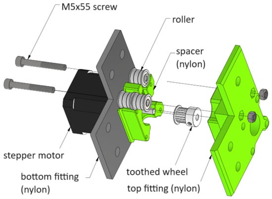
Figure 4.
Exploded view of the 2nd corner.
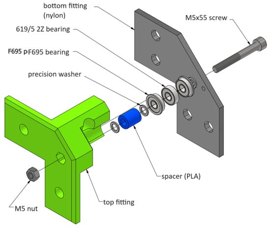
Figure 5.
Exploded view of the 4th corner.
The printer uses LDO-42STH60-2004MAC stepper motors (LDO Motors, Shenzhen, China) for all drives, which were available prior to the design. These motors have a 0.9° step angle, meaning 400 steps are required for one full revolution, with a holding torque of 6 kg/cm. The key advantage of these stepper motors is their ability to achieve precise positioning. The rails are MGN15H linear guides, also available before the design phase. The load capacity parameters, as indicated in the datasheet, were deemed acceptable for the application, as they only need to support the weight of the bridge and the print head, which is negligible compared to the maximum load capacity of the linear guides (the base static load rating is 9.11 kN) (Figure 6).
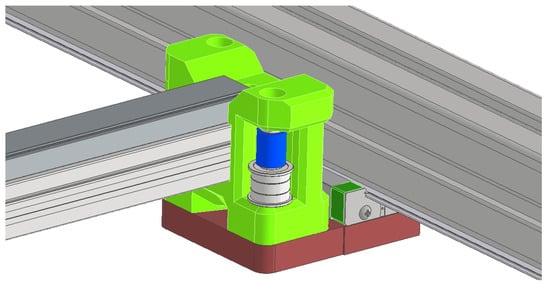
Figure 6.
The right-side bridge mounting unit.
GATES fiberglass-reinforced timing belts were used, which are 9 mm wide and have a 2 mm pitch. The dimensions of the toothed pulleys and rollers were selected to match the parameters of the belt.
2.2. Design and Dimensioning of the Z-Axis Drive
The drive system of the Z-axis raises and lowers the print bed. This movement is performed by a trapezoidal screw (TR12X3 C45), which is right-handed and 1 m long. The machine has been designed so that the screw does not need to be cut, allowing the full length to be utilized. The screw construction is designed as a rod supported from below, making it simpler and more cost-effective to implement. A 3D-printed component has been designed for the top end, which includes a bearing housing capable of accommodating a 16001 2Z dust-proof bearing to secure the rod against horizontal movement. Additionally, this component is designed for attaching the LDO-42STH60-2004MAC stepper motor, which has a 5 mm shaft diameter, connected to the TR12 screw via a 5 × 12 coupling. This coupling is able to absorb any misalignment and axial movement, thereby protecting the motor bearings.
The arms supporting the print bed are constructed from 40 × 40 ITEM aluminum profiles. These are designed to be attached at one end to the linear carriage via a printed elbow element, with the screw passing through a 16 mm diameter hole in the middle of the profile, where the nut is also mounted. The design of the Z-axis drive can be seen in Figure 7.
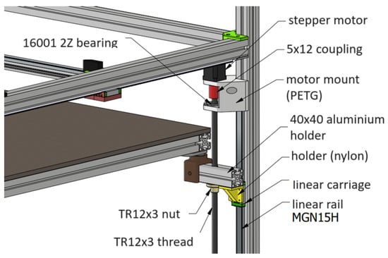
Figure 7.
The design of the Z-axis drive.
The machine frame was originally designed with a support point under each spindle, so for the support of a specific spindle, a simple 3D-printable bearing housing was designed into which a 51101 axial bearing can be fitted. This is because large axial forces are generated at this location, whereas radial forces are minimal. According to the bearing catalog, the static load capacity is 15.3 kN, which is more than sufficient to meet the previously mentioned design requirements. The spindle is secured using a nut-and-counter-nut connection (Figure 8).
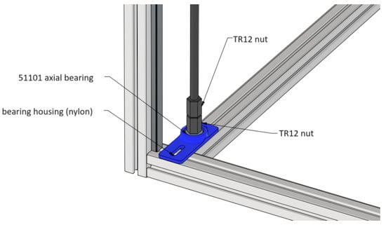
Figure 8.
The bearing of the lead screw with trapezoidal thread at the end of the spindle.
It is important to note that from the deflection perspective, the ideal design would involve a suspended spindle, as this would result in only tensile stress and no deflection. In contrast, with a supported rod, compressive stress would occur, potentially leading to deflection. For this reason, the spindle was checked for deflection, and a static load analysis was performed. During the simulation, it was estimated that each spindle should be able to withstand a maximum weight of 30 kg with a safety factor of 2, based on the previously mentioned loading conditions. Additionally, the spindle was checked at the table’s upper dead point, as this is where the deflection length of the rod is greatest.
This estimate is not entirely realistic, as during the initial stages of printing, after the first layers are deposited, the table would not yet support such a large amount of material, and the weight of the table itself is negligible. Therefore, if the deflection of the printed rod is deemed acceptable under the given conditions, the design can be considered adequate for practical use.
In the simulation (Figure 9), the materials of the individual components were inputted, and constraints were applied to connect them in a manner that reflects the real-world setup. Boundary conditions were then applied to the backside of the linear rail and other mounting points. Finally, a 300 N load was defined at the table’s support point, and the analysis was run. The greatest deflection was observed in the figure, where it can be seen that the value is less than 0.2 mm, suggesting that the design will be sufficient. It should be noted that in practice, larger displacements may occur due to imperfections in the fit between the lead screw and the nut, or the presence of play, but the spindle’s deformation is considered to be within acceptable limits.
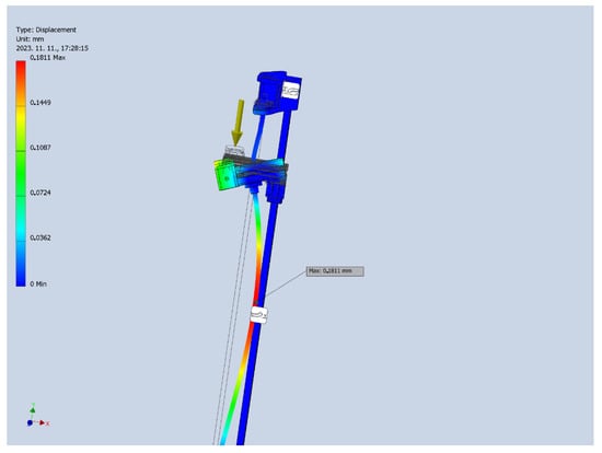
Figure 9.
Simulation of the deflection of the trapezoidal lead screw.
Similar to the previous case, MGN15H linear rails and carriages were used here as well, but in a vertical arrangement, 1 m in length, mounted to the machine frame.
2.3. Printer Bed
The frame of the printer bed was also designed using 40 × 40 mm ITEM aluminum profiles. A 825 × 825 × 10 mm wooden plate was provided, and this had to be used. he printer bed is supported at three points (at the two front corners and the center of the rear side), forming an equilateral triangle. It must be ensured during subsequent prints that the center of mass of the printed object is located within the area enclosed by the sides of this triangle, thereby preventing the risk of tipping. 3D-printed joints were designed for the support points. The spherical part is to be screwed onto the bed frame, while the counterpart attaches to the aluminum arm. Efforts were made to design everything in such a way that the structure can be easily adjusted during assembly to account for any potential manufacturing inaccuracies. The design of the printer bed support can be seen in Figure 10.
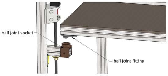
Figure 10.
The design of the printer bed support.
2.4. Printer Head
The base of the printer head was designed as a carrier unit, which can be screwed onto the linear carriage running on the bridge. Additionally, connection points were integrated for the four incoming toothed belts. The belts can be attached to the carrier unit using toothed plates. Furthermore, four screw holes were designed on the side of the carrier unit, which can be used to secure any printhead/nozzle in the future without disassembling the carrier unit Figure 11.
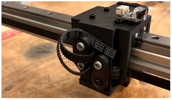
Figure 11.
Design of the printer head.
3. Development of Different Feeding Systems
Recent research in 3D concrete printing has emphasized the importance of advanced mixing techniques to achieve consistent material quality and reliable extrusion. Inline mixing integrates the mixing action directly into the material delivery path, reducing segregation and improving homogeneity during pumping and extrusion [28]. Secondary mixing approaches, including near-nozzle mixing heads, have been shown to enable controlled blending of reactive components immediately prior to deposition, improving print quality and structural integrity [29,30]. Additionally, real-time quality control methods, such as sensor-based monitoring of extrusion forces, layer geometry, and rheological properties, have been developed to provide feedback and adjust process parameters during printing, enhancing process stability and product consistency [28]. These advancements form an important context for the current work, as they highlight strategies to manage fresh material behavior and ensure print reliability.
Recent industrial developments in concrete 3D printing have introduced near-nozzle and secondary mixing solutions to improve material homogeneity and buildability. Commercial systems developed by MAI Mixing & Pumping, CyBe Construction and VERTICO primarily target large-scale construction applications, focusing on high material throughput, automated process control, and integration with proprietary material formulations [31,32,33].
While the present work adopts a similar conceptual principle by addressing material processing close to the nozzle, its objective and technical realization differ fundamentally. Rather than presenting a single finalized mixing head, the following section documents the stepwise development and experimental comparison of multiple feeding system configurations. The proposed feeding system was designed as a laboratory-scale, modular research platform, emphasizing mechanical simplicity, short material paths, and geometry-driven control of extrusion behavior. Instead of relying on complex sensor-based automation, the system enables direct investigation of material rheology, thixotropy, and segregation through adjustable screw geometry, minimized diameter reductions, and integrated mechanical mixing at critical constrictions.
This approach allows systematic evaluation of cement-based and alkali-activated materials under controlled experimental conditions and provides a flexible framework for material development and extrusion optimization, rather than serving as an industrial construction printing solution. The innovation of this work lies in the systematic development methodology and experimental design logic, rather than in a single hardware component.
One of the most exciting questions in 3D printing of cement and alkali-activated cement is how to deposit the material, how to transport it to the nozzle, and then deliver it onto the print bed. The project involved extensive experimentation, testing multiple designs, and making modifications before arriving at an optimally functioning system. The different depositing methods are presented chronologically, as the process progressed towards the final solution.
During the development process, one of the most critical aspects is the flowability of the material. It is essential to find a balance between printability and the buildability of successive layers. The next step is determining the open time, which refers to the period between the completion of mixing and the loss of printability. Additional key development guidelines include ensuring a uniform material flow, minimizing the length of the piping system, and reducing flow restrictions.
From a material development perspective, the goal is to design a feeding system capable of 3D printing materials with lower flowability. This is of great importance because, with a lower water content, the porosity of the final product is reduced, thereby improving its mechanical properties.
The operation of all feeding systems was carried out using an LDO-42STH60-2004MAC stepper motor, as stepper motors allow for precise control. Furthermore, each design was equipped with a vibrated material container. The vibration causes the material to accumulate at the bottom of the container and improves its flowability, thereby enhancing printability.
During the experimental trials, the printing conditions and operational parameters were kept as consistent as possible in order to ensure comparability between the investigated configurations. The applied nozzle inner diameter was 5 mm or 10 mm, depending on the material composition. The layer height was defined as 20% of the nozzle inner diameter (e.g., 1 mm for a 5 mm nozzle), while the printing speed was set to 5 mm/s. In all cases, vibration-assisted feeding was applied during extrusion to promote continuous material flow and extrusion stability. These parameters were selected based on preliminary trial prints to achieve stable extrusion and reliable layer formation, and were maintained constant during comparative experiments to isolate the effects of feeding system geometry and material behavior.
3.1. Feeding System Equipped with a Peristaltic Pump
Above the printing level, a 0.5 m cubic frame made of 20 × 20 mm BOSCH aluminum profiles was suspended on springs. A peristaltic pump was mounted on this frame to transfer the material from a vibrated container through a 1 m long tube (5 mm inner diameter, 20% layer height relative to the inner diameter meaning a 1 mm one here, and a printing speed of 5 mm/s) to the print head. Vibromotors were attached to the frame, as the vibration was expected to improve the flow properties of the printed material. The first test print used a geopolymer composition, as presented in Table 2, in column a.
Table 2.
Geopolymer compositions.
Initially, the material exhibited good printability; however, it later became compacted, as shown in Figure 12a. This was caused by the material segregating due to the vibration, with the sand settling at the bottom of the container and clogging the system.
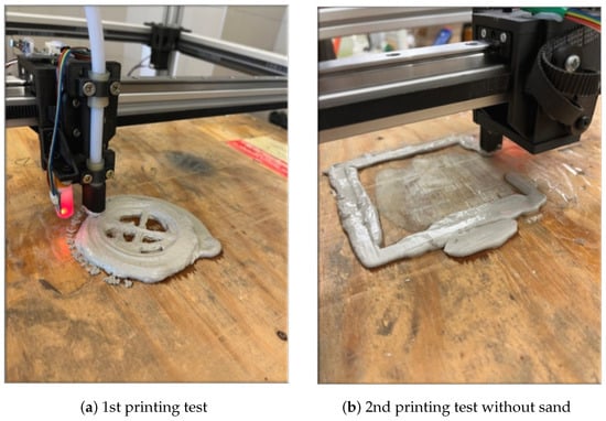
Figure 12.
Overview of the geopolymer compositions for the printing tests.
In the second test print, the sand was omitted from the composition, which reduced the degree of segregation (Table 2, in column b). The peristaltic pump struggled to extrude the material, as the paste compacted and clogged the tubing system, as shown in Figure 12b.
The third test print (Figure 13) was carried out in a pressurized setup using a cement–water composition, with the following mixing ratio determined through a multi-step iterative process (Table 3). Subsequently, the cement-based composition was used multiple times in test prints, as it provided a simpler way to evaluate the design of the feeding system. CEM II/B-S 42.5 N cement (Duna-Dráva Cement, Vác, Hungary) was used in this study. Tests involving geopolymer-containing mixtures were generally performed only after these preliminary trials.
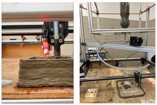
Figure 13.
Cement printing test (left), peristaltic pump and vibrated tank (right).
Table 3.
Composition of the cement mixture.
A major disadvantage of the peristaltic pump is that it delivers material in a pulsating manner. For example, when attempting to print a straight line on the print bed, the walls of the line do not remain parallel to each other but instead fluctuate in a sinusoidal pattern. This phenomenon causes inaccurate printing and deformation between layers.
The design has been modified by adding an adapter to the peristaltic pump, which has been mounted on the print head in such a way that the material is pressed through a minimal length of tubing (Figure 14). Despite this, the material delivery was still unsatisfactory, as the peristaltic pump is only suitable for feeding more fluid materials, while compositions containing sand tend to clog the pump almost immediately.
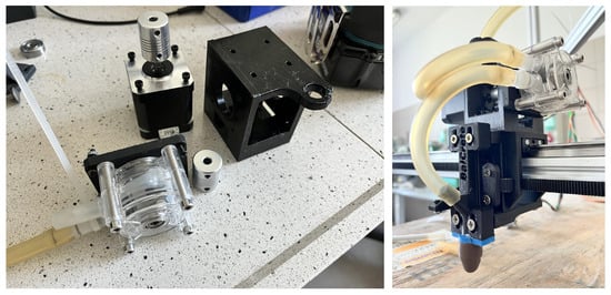
Figure 14.
Peristaltic pump installed on the print head.
3.2. Large-Scale, Horizontally Oriented 3D-Printed Extruder
The poor material transport and pulsed material flow of the peristaltic pump necessitated its replacement. The peristaltic pump has been replaced with an extruder, which provides a continuous material flow during printing and is also capable of extruding less viscous materials.
Initially, extruder screws with diameters of 40 mm, 30 mm, and then 16.8 mm were designed. Since the nozzle used has a diameter of only 5 mm, smaller screws proved to be more suitable, as the larger diameter required higher power, and the material was overly compacted at the constrictions.
The 40 mm and 30 mm screws were mounted on a bracket above the printing plane and were connected to the nozzle on the print head via a long tube with an inner diameter of 5 mm (Figure 15). The diameter of the tube should be minimized to the smallest size through which the material can still pass, thereby reducing the amount of material in the system.
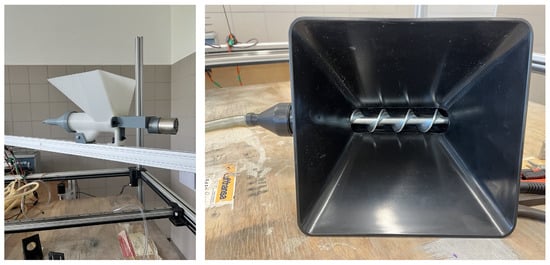
Figure 15.
Custom-designed 3D-printed D40 extruder (left), commercially available D30 extruder (right).
To describe the constrictions, a reduction ratio was introduced, which should ideally approach 1. Thus, this value indicates the relationship between the diameter of the extruder screw and the diameter of the printing nozzle. For example, represents the reduction ratio.
The printing tests were conducted on an exploratory basis using the cement-based composition presented in Table 3. However, the high power demand placed significant stress on the LDO-42STH60-2004MAC stepper motors, which have a holding torque of only 6 kg/cm—insufficient for the required load. Consequently, the use of large-diameter extruder screws (40 mm and 30 mm) had to be abandoned after the initial experiments, as the motors were unable to provide the necessary material output.
3.3. Small-Scale, Horizontally Oriented 3D-Printed Extruder
The 30 mm and 40 mm diameter extruder screws proved unsuitable under the applied parameters due to their high power demand. Therefore, a 16.8 mm diameter screw was designed that can be mounted directly onto the print head using a quick-release mechanism, requiring the material to be fed directly into the extruder’s container (Figure 16).
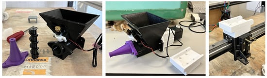
Figure 16.
Assembly of D16.8 mm horizontal layout extruder on the print head.
The 16.8 mm diameter was chosen as it represented the smallest possible size that still allowed for an appropriate screw geometry while accommodating a 5 mm diameter shaft in the center. The extruder screw was mounted on this 5 mm shaft, which was connected to the stepper motor’s 5 mm diameter shaft via a 5 × 5 mm shaft coupling. This configuration ensured mechanical compatibility and efficient torque transmission between the motor and the screw, while maintaining the proper screw geometry despite the reduced diameter.
A test print was carried out using the composition listed in Table 4. The printing process was uniform, and the layers aligned accurately; however, compaction and clogging within the tube have been observed occasionally at the constriction points. The cloggings observed at the constrictions can also be attributed to the fact that the porous 3D-printed plastic components partially filter the material, allowing water to leak through the walls and out of the system. This phenomenon can be mitigated by applying a lacquer coating to the 3D-printed extruder components. Figure 17 shows a restrictor fitting, illustrating that clogging during printing does not occur directly at the 5 mm cross-section but rather develops gradually as an increasingly thick layer along the inner surface of the fitting.
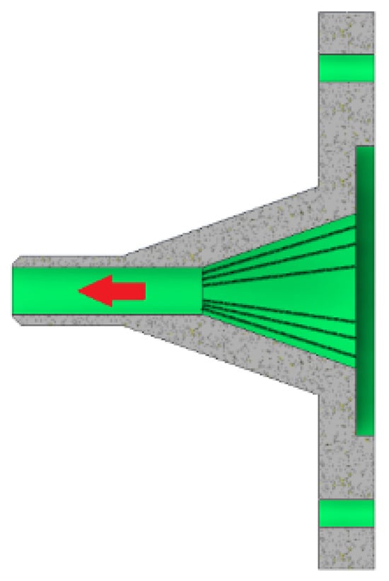
Figure 17.
Clogging of the 3D-printed (PETG) restrictor from the direction of the shell surface.
The small-scale, horizontally oriented feeding system designed proved suitable for printing cement-based compositions without sand. However, material segregation began relatively quickly in the vibrated container (Figure 18, right). Additionally, as shown on the left side of Figure 18, the printed layers are straight, which can be attributed to the feeding method—there was no pressure pulsation in the material flow during printing.
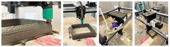
Figure 18.
Cement 3D printing by horizontal layout extruder on the print head.
3.4. Vertical Layout Extruder on the Print Head
The core concept of the design is the implementation of a vertically oriented extruder mounted directly on the print head for material extrusion (Figure 19). The primary advantage of this configuration is that the material only needs to be pushed through a minimal tube length before deposition, thereby reducing the risk of compaction.
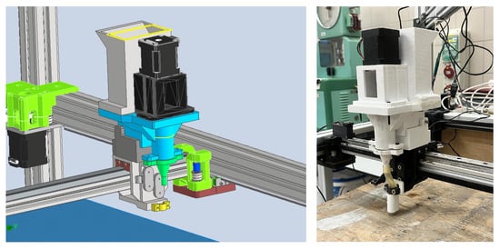
Figure 19.
Vertical layout extruder on the print head.
A 300 cm3 container was attached to the print head, supplying the extruder screw with printable material through a lateral inlet. A vibration motor was mounted on the side of the container to ensure that the mixed cement accumulates at the bottom. Previous experiments have shown that operating the vibration motor is essential for the smooth and continuous feeding of the material.
An additional innovation in the design is that the extruder screw diameter has been reduced by 40% compared to the previous version, resulting in a diameter of only 12 mm. Printing experiences with earlier configurations indicate that the ratio between the nozzle diameter and the extruder screw diameter plays a crucial role in preventing material compaction. The ideal ratio should be 1:1 to minimize the probability of clogging. As the extruder screw diameter increases relative to the nozzle diameter, the likelihood of system clogging rises proportionally, thereby reducing the printable time window for a given material. In this case, the nozzle diameter is 5 mm, while the extruder diameter is 12 mm—2.4 times larger—which does not yet produce a sufficient diameter difference to cause compaction issues during operation.
Since this design was found to be the most suitable, the printability of compositions containing a dispersed phase was tested instead of the previously used cement–water mixtures. For the first printing test, the composition shown below was selected, which included a plasticizer to improve flowability (Table 4).
Table 4.
Composition of the cement-based mixture containing sand.
Table 4.
Composition of the cement-based mixture containing sand.
| Component | Amount (wt%) |
|---|---|
| Cement | 22.1 |
| Sand | 66.4 |
| Tap water | 11.1 |
| Plasticizer | 0.4 (2% of cement) |
A problem was encountered due to the fact that the gap between the extruder screw and the cylinder wall was only 0.6–0.7 mm, which is comparable to the size of the sand particles, which is smaller than 2 mm. As a result, the sand grains became lodged in the gap, stopping the printing process. The sectional view of the extruder is illustrated in Figure 20.
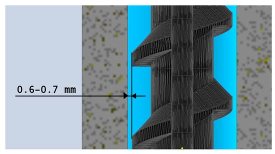
Figure 20.
Sectional view of the vertical feeder.
A 0.4 wt% plasticizer resulted in excessive flowability; however, due to the sand particle size distribution rendering the material completely unsuitable for 3D printing, experimentation with sand-containing compositions was discontinued.
Taking the particle size limitations into account, cement compositions containing glass powder were subsequently investigated. Glass powder does not cause jamming, as its particle size does not exceed 130 μm. An additional advantage of using recycled glass powder is that it supports the development of a circular economy, while also providing an environmentally and waste-management-friendly solution.
Two compositions were tested: in the first case, 0.4 wt% plasticizer was used, but since this resulted in excessive fluidity, the plasticizer content was reduced to 0.1 wt% in the second printing trial (Table 5).
Table 5.
Compositions of two cement-based mixtures.
Both compositions were too fluid, with the material spreading immediately upon deposition on the print bed; therefore, a further reduction in the plasticizer content was deemed necessary.
3.5. Horizontally Oriented Extruder with Continuous Mixing
In previous printing trials, it was observed that compaction consistently occurred at the constriction after a certain operating time. To eliminate this issue, an extruder screw was designed to provide continuous mixing across the entire cross-section of the constriction, thereby preventing system clogging. The difference between the two screw designs is illustrated in Figure 21.
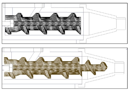
Figure 21.
Screw design with mixing at the constriction (lower) and without mixing (upper).
In previous designs, a recurring issue was material segregation and settling in the container. To eliminate this phenomenon, the container was redesigned as a rotational body instead of a square shape, allowing the installation of a mixing paddle to provide continuous agitation. The paddle’s 5 mm diameter shaft was connected to the stepper motor via a 5 × 5 mm shaft coupling and supported with an F695 flanged ball bearing to relieve the load on the motor’s bearings. The 3D model and construction of the feeder is shown in Figure 22.
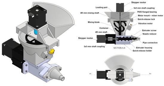
Figure 22.
Construction of the mixing-container feeding system.
Additionally, a vibration motor was incorporated into the feeder to ensure proper flow of the material to be printed. After completing the 3D designs, the individual plastic components were printed from carbon-fiber reinforced nylon filament. Subsequently, the feeder was assembled, and all joints were sealed. An image of the 3D-printed components is shown in Figure 23.
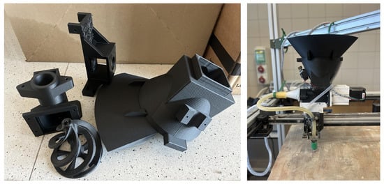
Figure 23.
3D-printed carbon-fiber reinforced nylon feeder components (left), assembled feeder (right).
The feeder was mounted directly on the print head. This arrangement was chosen because the length of the tube connecting the extruder to the nozzle must be minimized to reduce internal friction and material losses. Additionally, a quick-release mounting system was implemented to facilitate cleaning after each printing session. The feeder mounted on the 3D printer is shown in Figure 23. In the subsequent printing tests, only this feeding system was used.
3.5.1. Test of Composition Without Dispersed Phase (Slag-Based Geopolymer)
During the experiments, a 5 mm diameter rubber tube and nozzle were used. Based on previous experience, compositions without a dispersed phase can still be 3D-printed without issues at this cross-section. Through a multi-step iterative process, the appropriate consistency was established, as recorded in Table 6.
Table 6.
Slag-based geopolymer composition without dispersed phase.
The composition proved to be highly printable, maintaining its shape, and the constricted nozzle opening did not clog. Under vibration, the material exhibited pronounced thixotropic behavior, behaving like a solid material at rest while becoming fluid under strain or vibration—an advantageous property for 3D printing.
During printing, the appropriate speed and extrusion parameters had to be initially adjusted. As observed in Figure 24, discontinuities occurred due to the low material deposition, resulting in a test specimen that was not fully dense, which could have negatively affected subsequent mechanical strength tests.
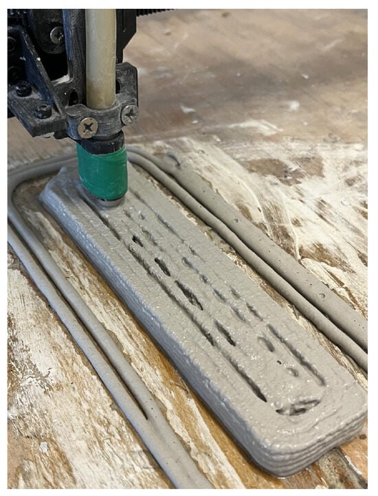
Figure 24.
Test printing of geopolymer composition without dispersed phase.
The mechanical properties of the material were evaluated at 7 days of age in accordance with the EN 196-1 standard [34]. Measurements were performed using a CONTROLS Automax5 testing machine (CONTROLS S.p.A., Liscate (Milan), Italy). The tests were conducted with applied loading forces of 2400 N/s for compressive strength and 50 N/s for flexural strength. Three specimens measuring 40 × 40 × 160 mm were prepared for the strength tests.
First, the flexural strength of the specimens was assessed. During testing, the specimens fractured under the bending load, and the compressive strength was subsequently measured on each fractured piece individually. Accordingly, two specimens were used for the compressive strength test for each sample, following the prescribed testing procedures. The average flexural strength was , while the compressive strength was (Table 7).
Table 7.
Mechanical strength tests of slag-based geopolymer composition without dispersed phase.
As shown in Figure 25, cracks were already present on the specimen prior to the strength test. Additionally, it is evident that the fracture during testing propagated along one of the main pre-existing cracks. Furthermore, the failure mode of the plain 3D-printed concrete beams was governed by classical flexural cracking, comparable to that observed in conventionally cast plain concrete specimens, with no qualitative change in the governing fracture mechanism attributable to the printing process.
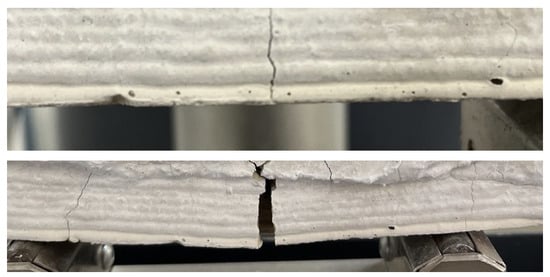
Figure 25.
Specimen without dispersed phase before (top) and after (bottom) the flexural strength test.
According to the literature, geopolymer specimens produced by conventional casting methods can reach a compressive strength of about 20 MPa after 4 h, while the flexural strength may reach up to 10 MPa [14]. The results obtained from the strength tests (0.43 MPa in flexural strength and 7.73 MPa in compressive strength) were lower compared to these values, which can be attributed to several factors. According to the EN 196-1 standard [34], the compressive and flexural strengths of standard Portland cement paste specimens prepared using conventional casting techniques are determined on 40 × 40 × 160 mm prisms. After 28 days of curing, the compressive strength typically reaches 30–50 MPa, while the flexural strength is about 6–10 MPa, depending on the cement type and water-to-cement ratio.
One of the main reasons for the relatively low strength results is that, during 3D printing, the material deposition was not entirely homogeneous, leading to the formation of pores within the samples. Additionally, the surfaces of the printed specimens were not completely smooth, remaining uneven due to the 3D printing process, which resulted in non-uniform load distribution during the strength tests. This improper load distribution could have caused premature fractures and lower apparent strength values. Therefore, in future experiments, we plan to sand down the surfaces of the printed specimens prior to testing to obtain more accurate and reliable results.
3.5.2. Test of Composition with Dispersed Phase (Slag-Based Geopolymer)
Since cracks appeared in the specimens during the previous experiment, compositions containing glass powder were tested next. The glass powder used had a particle size smaller than 130 μm. For the glass powder–containing compositions, the rubber tube and nozzle were replaced with larger 10 mm diameter components, as the 5 mm diameter print head in earlier designs was not suitable for printing compositions with a dispersed phase; in such mixtures, larger particles or inhomogeneous structures can easily clog the narrow cross-section.
Through a multi-step iterative process, the appropriate consistency was established, as recorded in Table 8. The material proved to be highly printable, maintaining its shape stably, showing no tendency to segregate, and the constriction of the print head did not cause clogging.
Table 8.
Slag-based geopolymer composition with dispersed phase.
Figure 26 clearly illustrates the thixotropic behavior of the material. During the initial stage of printing, vibration was not applied, which resulted in insufficient material flow, causing it to behave similarly to a solid material. Consequently, a porous internal structure developed within the affected layers of the 3D-printed specimen. In contrast, when vibration was applied, the geopolymer returned to a fluid state, exhibiting nearly ideal printability characteristics.
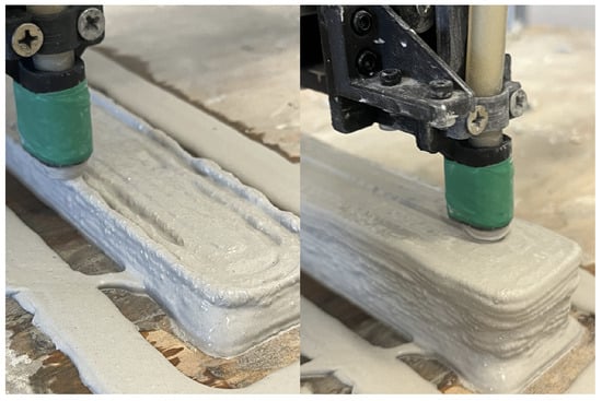
Figure 26.
Illustration of the effect of container vibration.
Figure 27 also illustrates the effect of vibration on the thixotropic behavior of the material and, consequently, on its extrudability. In the wider sections of the specimen, increased vibration was applied, which resulted in a significantly greater amount of deposited material. In contrast, during the printing of narrower layers, vibration was turned off, which affected the material flow and the formation of the layers. However, not only vibration but also extrusion speed, printing speed, and mixing intensity have a significant influence on the material deposition. Therefore, the coordinated adjustment of these parameters is essential to achieve optimal printing quality.
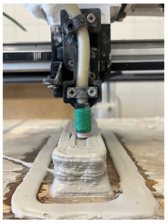
Figure 27.
Illustration of material deposition issues.
The mechanical properties of the material were also tested at 7 days of age according to the EN 196-1 standard [34]. Three specimens with dimensions of 40 × 40 × 160 mm were prepared for the strength tests. Based on the results, the average flexural strength of the specimens was , while their average compressive strength was . These values are similar to those obtained for the composition without a dispersed phase, indicating that no significant mechanical improvement was observed with the addition of the dispersed phase (Table 9).
Table 9.
Strength tests of slag-based geopolymer composition with dispersed phase.
In the case of the glass powder-containing composition, the specimen did not exhibit crack formation after curing, and no visible surface cracks were observed (Figure 28).
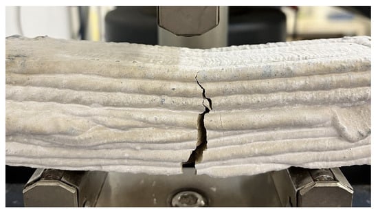
Figure 28.
Flexural strength test of the specimen with dispersed phase.
The strength values of the glass powder-containing geopolymer were similar to those of the composition without glass powder. However, the strength-reducing phenomena previously described, such as pore formation and uneven load distribution resulting from surface irregularities, were also observed in this case. Although surface irregularities inherent to the printing process may act as local stress concentrators, the observed failure mode was comparable to that of conventionally cast plain concrete specimens, and no pronounced scatter was observed in the flexural test results, suggesting that their influence on the overall failure behavior was limited. Nevertheless, the glass powder-containing formulation proved to be fully printable, and the printed specimens did not develop cracks, making it particularly suitable for 3D printing applications with the current feeding system. For a more precise evaluation of the printed bodies, further detailed investigations are required.
4. Discussion and Conclusions
Drawing on the experimental investigations presented in Section 3.3, Section 3.4 and Section 3.5, the main contribution of this work lies in identifying and experimentally validating the key design parameters that govern printability when processing fine-grained cementitious and alkali-activated materials through small-diameter nozzles. Based on the systematic development and testing of multiple feeding system configurations, the following critical parameters were identified:
- Screw-to-nozzle diameter ratio : Experimental results indicate that maintaining this ratio as close as possible to unity is essential to prevent material compaction and premature clogging. Ratios exceeding approximately 2.5–3 significantly reduce the printable time window, even for mixtures without a dispersed phase.
- Length of the material transport path: Minimizing tube length between the extruder and nozzle is critical to reduce pressure losses, internal friction, and segregation. Mounting the feeder directly on the print head proved to be particularly effective in improving extrusion stability.
- Continuous mixing at the constriction: Introducing active mixing in the narrowing section of the extruder significantly reduces time-dependent clogging by preventing particle accumulation and local densification.
- Container geometry and material homogenization: Rotationally symmetric containers combined with mechanical mixing and vibration were found to be essential to suppress segregation and to maintain a consistent feed rate over time.
- Exploitation of thixotropic behavior: The combined use of vibration and controlled extrusion enables the material to behave as a solid at rest while becoming fluid under shear, which is a key requirement for stable layer-by-layer construction.
These parameters provide practical design guidelines that can be directly applied to the development and scaling of extrusion-based 3D printers for cementitious and geopolymer materials.
In summary, a custom 3D printer was developed to address the challenges associated with printing conventional and alkali-activated cements (AAC), with particular emphasis on material extrusion and structural design. The printer’s design was extensively modified to enable the extrusion of less flowable mixtures containing a dispersed phase. Several feeding methods were tested, including peristaltic pumps as well as horizontally and vertically arranged extruders.
Based on experimental results and practical experience, it was found that the horizontal extruder configuration provided the most suitable feeding method, as it ensured the most stable and efficient material flow during printing. The comparison of the different extrusion systems is summarized in Table 10.
Table 10.
Summary of the tested feeding systems.
Future development directions are defined by several key considerations. It is essential to aim for a screw-to-nozzle diameter ratio close to 1, as this greatly contributes to preventing clogging. Furthermore, minimizing tube lengths is advisable to reduce material loss and internal friction. The automation of mixing and vibration processes is also of fundamental importance, as it ensures mixture homogeneity and helps prevent component segregation.
The applied material composition should exhibit thixotropic behavior—behaving as a solid material at rest while becoming fluid under strain—which enhances printing stability and layer buildability. Increasing the setting time is also recommended to allow longer workability and the printing of more complex geometries.
Following these principles, future development will focus on optimizing both the feeding system and the material composition, as well as performing detailed analyses of printed specimens using CT (computed tomography) technology. CT investigations would primarily focus on porosity levels and the quality of interlayer bonding, as these factors significantly influence the final structure’s mechanical performance and durability.
Author Contributions
Conceptualization, B.C.; Methodology, A.B., A.K. and B.C.; Software, A.K.; Validation, A.E. and T.K.; Formal analysis, A.B.; Investigation, B.C. and A.B.; Resources, A.E.; Data curation, B.C.; Writing—original draft preparation, B.C.; Writing—review and editing, A.B., A.E., A.K. and T.K.; Visualization, B.C.; Supervision, A.E.; Project administration, A.E. and T.K.; Funding acquisition, A.E. All authors have read and agreed to the published version of the manuscript.
Funding
This research received no external funding.
Data Availability Statement
The data presented in this study are available upon request from the corresponding author.
Conflicts of Interest
The authors declare no conflicts of interest.
References
- Duballet, R.; Baverel, O.; Dirrenberger, J. Classification of building systems for concrete 3D printing. Autom. Constr. 2017, 83, 247–258. [Google Scholar] [CrossRef]
- Zhong, H.; Zhang, M. 3D printing geopolymers: A review. Cem. Concr. Compos. 2022, 128, 104455. [Google Scholar] [CrossRef]
- Mujeeb, S.; Samudrala, M.; Lanjewar, B.A.; Chippagiri, R.; Kamath, M.; Ralegaonkar, R.V. Development of Alkali-Activated 3D Printable Concrete: A Review. Energies 2023, 16, 4181. [Google Scholar] [CrossRef]
- Tarhan, Y.; Tarhan, İ.H.; Şahin, R. Comprehensive Review of Binder Matrices in 3D Printing Construction: Rheological Perspectives. Buildings 2025, 15, 75. [Google Scholar] [CrossRef]
- Arnold, H. The Recent History of the Machine Tool Industry and the Effects of Technological Change. 2001. Available online: https://www.researchgate.net/publication/228947863_The_recent_history_of_the_machine_tool_industry_and_the_effects_of_technological_change (accessed on 13 January 2026).
- Abdulhameed, O.; Al-Ahmari, A.; Ameen, W.; Mian, S.H. Additive manufacturing Challenges, trends, and applications. Adv. Mech. Eng. 2019, 11, 1–27. [Google Scholar] [CrossRef]
- Mishra, J.; Babafemi, A.J.; Combrinck, R. Limitations and Research Priorities in 3D-Printed Geopolymer Concrete: A Perspective Contribution. Ceramics 2025, 8, 47. [Google Scholar] [CrossRef]
- Shilar, F.A.; Ganachari, S.V.; Patil, V.B.; Bhojaraja, B.; Yunus Khan, T.; Almakayeel, N. A review of 3D printing of geopolymer composites for structural and functional applications. Constr. Build. Mater. 2023, 400, 132869. [Google Scholar] [CrossRef]
- Dilberoglu, U.M.; Gharehpapagh, B.; Yaman, U.; Dolen, M. The Role of Additive Manufacturing in the Era of Industry 4.0. Procedia Manuf. 2017, 11, 545–554. [Google Scholar] [CrossRef]
- Wong, K.V.; Hernandez, A. A Review of Additive Manufacturing. ISRN Mech. Eng. 2012, 2012, 208760. [Google Scholar] [CrossRef]
- Paritala, S.; Singaram, K.K.; Bathina, I.; Khan, M.A.; Jyosyula, S.K.R. Rheology and pumpability of mix suitable for extrusion-based concrete 3D printing—A review. Constr. Build. Mater. 2023, 402, 132962. [Google Scholar] [CrossRef]
- Tajunnisa, Y.; Arrafid, R.N.; Bayuaji, R.; Nurhadi, H. Rheology Analysis of 3D Printed Geopolymer Based on High Calcium Fly Ash. IPTEK J. Eng. 2024, 10, 196–204. [Google Scholar] [CrossRef]
- Si, W.; Khan, M.; McNally, C. A Comprehensive Review of Rheological Dynamics and Process Parameters in 3D Concrete Printing. J. Compos. Sci. 2025, 9, 299. [Google Scholar] [CrossRef]
- Soósné Balczár, I. Mi is az a geopolimer és mire lehet használni? Betonújság, 15 April 2018. Available online: https://www.betonujsag.hu/lapszamok/cikk/2050/mi-is-az-a-geopolimer-es-mire-lehet-hasznalni (accessed on 13 January 2026).
- Ricciotti, L.; Apicella, A.; Perrotta, V.; Aversa, R. Geopolymer materials for extrusion-based 3D-printing: A Review. Polymers 2023, 15, 4688. [Google Scholar] [CrossRef]
- DIN EN 197-1; Cement—Part 1: Composition, Specifications and Conformity Criteria for Common Cements. Deutsches Institut für Normung E.V.: Berlin, Germany, 2011. Available online: https://www.en-standard.eu/din-en-197-1-cement-part-1-composition-specifications-and-conformity-criteria-for-common-cements/ (accessed on 15 November 2025).
- Jaji, M.B.; Babafemi, A.J.; van Zijl, G.P. Mechanical performance of extrusion-based two-part 3D-printed geopolymer concrete: A review of advances in laboratory and real-scale construction projects. Mater. Today Sustain. 2025, 31, 101131. [Google Scholar] [CrossRef]
- Bao, T.M.P.; Yeakleang, M.; Abdelouhab, S.; Courard, L. Testing Mortars for 3D Printing: Correlation with Rheological Behavior. Materials 2024, 17, 5002. [Google Scholar] [CrossRef]
- Kozub, B.; Sitarz, M.; Gądek, S.; Ziejewska, C.; Mróz, K.; Hager, I. Upscaling of Copper Slag-Based Geopolymer to 3D Printing Technology. Materials 2024, 17, 5581. [Google Scholar] [CrossRef] [PubMed]
- Al-Noaimat, Y.A.; Ghaffar, S.H.; Chougan, M.; Al-Kheetan, M.J. A review of 3D printing low-carbon concrete with one-part geopolymer: Engineering, environmental and economic feasibility. Case Stud. Constr. Mater. 2023, 18, e01818. [Google Scholar] [CrossRef]
- Elhag, A.B.; Mabrouk, A.; Ghazouani, N.; Nasir, U. Advances in Sustainable 3D-Printed Geopolymer Concrete: Materials, Performance, and Environmental Impact in Next Generation Green Construction. JOM 2025, 77, 8917–8955. [Google Scholar] [CrossRef]
- Nodehi, M.; Ozbakkaloglu, T.; Gholampour, A. Effect of supplementary cementitious materials on properties of 3D printed conventional and alkali-activated concrete: A review. Autom. Constr. 2022, 138, 104215. [Google Scholar] [CrossRef]
- Wu, Y.; Liu, C.; Bai, G.; Liu, H.; Cao, S.; Ma, Z.; Sun, Y. Effect of time interval on the interlayer adhesion of 3D printed concrete with recycled sand: Multi-factor influencing mechanisms and superabsorbent polymer enhancement. Addit. Manuf. 2024, 86, 104206. [Google Scholar] [CrossRef]
- Rehman, A.U.; Kim, J.H. 3D Concrete Printing: A Systematic Review of Rheology, Mix Designs, Mechanical, Microstructural, and Durability Characteristics. Materials 2021, 14, 3800. [Google Scholar] [CrossRef] [PubMed]
- Harbouz, I.; Roziere, E.; Yahia, A.; Loukili, A. Printability assessment of cement-based materials based on rheology, hydration kinetics, and viscoelastic properties. Constr. Build. Mater. 2022, 325, 126810. [Google Scholar] [CrossRef]
- Muthukrishnan, S.; Ramakrishnan, S.; Sanjayan, J. Technologies for improving buildability in 3D concrete printing. Cem. Concr. Compos. 2021, 122, 104144. [Google Scholar] [CrossRef]
- Rig, R. V-Core 3.1 CAD & BOM. Available online: https://docs.ratrig.com/v-core-3-1/v-core-bom (accessed on 17 October 2025).
- Quah, T.K.N.; Tay, Y.W.D.; Lim, J.H.; Tan, M.J.; Wong, T.N.; Li, K.H.H. Concrete 3D Printing: Process Parameters for Process Control, Monitoring and Diagnosis in Automation and Construction. Mathematics 2023, 11, 1499. [Google Scholar] [CrossRef]
- Zhang, N.; Xia, M.; Sanjayan, J. Short-duration near-nozzle mixing for 3D concrete printing. Cem. Concr. Res. 2022, 151, 106616. [Google Scholar] [CrossRef]
- Zhang, N.; Sanjayan, J. Pumping-less 3D concrete printing using quick nozzle mixing. Autom. Constr. 2024, 166, 105609. [Google Scholar] [CrossRef]
- MAI Mixing & Pumping. MAI MULTIMIX-3D—3D Printing Mixing Technology. 2026. Available online: https://mai.at/en/product-range/3d-printing/ (accessed on 5 January 2026).
- CyBe Construction. CyBe 3D Concrete Printing Technology. 2026. Available online: https://cybe.eu/3d-concrete-printing/ (accessed on 5 January 2026).
- VERTICO. Advanced Printhead and Accelerator Technologies for 3D Concrete Printing. 2026. Available online: https://www.vertico.com (accessed on 5 January 2026).
- DIN EN 196-1; Methods of Testing Cement—Part 1: Determination of Strength. Deutsches Institut für Normung E.V.: Berlin, Germany, 2016. Available online: https://www.en-standard.eu/din-en-196-1-methods-of-testing-cement-part-1-determination-of-strength/ (accessed on 15 November 2025).
Disclaimer/Publisher’s Note: The statements, opinions and data contained in all publications are solely those of the individual author(s) and contributor(s) and not of MDPI and/or the editor(s). MDPI and/or the editor(s) disclaim responsibility for any injury to people or property resulting from any ideas, methods, instructions or products referred to in the content. |
© 2026 by the authors. Licensee MDPI, Basel, Switzerland. This article is an open access article distributed under the terms and conditions of the Creative Commons Attribution (CC BY) license.