Abstract
To tackle the limitations of conventional seismic design in high-intensity zones, as well as the challenges of inadequate isolation efficiency, excessive bearing displacement, and tensile stress in seismically isolated high-rise structures, this study presents a systematic solution for high-rise shear wall structures in seismic intensity 8 zones. The solution features a sparse isolator layout strategy, reducing isolator count by 40% to lower stiffness, while adding viscous dampers in the isolation layer for enhanced displacement control. Comparative nonlinear time history analyses were conducted to evaluate the inter-story shear distribution, energy dissipation allocation, and isolator responses. The results show that (1) the sparse layout achieves the best performance in controlling the bottom shear ratio and Maximum Considered Earthquake (MCE)-level responses (including displacement and tensile stress); (2) viscous dampers significantly reduce the shear forces in the lower stories and the energy dissipation of both isolators and the superstructure; (3) the combined strategy successfully resolves the issues of excessive isolator displacement and tensile stress under MCE. This research offers a standardized, economical, and highly resilient technical approach for seismically isolated high-rise projects in high-intensity seismic regions.
1. Introduction
Seismic isolation technology employs flexible isolation layers, typically laminated rubber bearings, to extend the structure’s natural period, thereby shifting its response away from the dominant frequency band of earthquake ground motions [1,2]. This reduces the transmission of seismic energy to the superstructure and effectively mitigates story shear forces and overturning moments [3]. Taking a frame–shear wall structure in seismic intensity zone 8 (0.30 g) in Gansu Province as an example, applying seismic isolation extended its fundamental period from 1.25 s to 3.71 s, with seismic forces in the superstructure reduced by over 60% [4]. In China’s high-seismicity regions, areas with a basic seismic intensity of 8 or higher account for 18% of the national territory [5]. Conventional seismic design remains the predominant engineering practice; however, its inherent limitations increasingly hamper improvements in building safety and functionality. Conventional seismic structural systems resist seismic actions by means of enhanced stiffness (e.g., via enlarged member sections) and ductile energy dissipation. In high-seismicity regions, these systems confront three primary challenges. First, to ensure adequate resistance for intensity 8 and above, shear walls often need to be 400–500 mm thick, as evidenced in projects like the Yuxi Public Rental Housing [6]. This significantly reduces usable space and, due to the increased structural stiffness, amplifies seismic forces, accelerating structural damage. Second, conventional structures typically exhibit limited seismic performance objectives, frequently entering deep plastic deformation under moderate and major earthquakes. Inter-story displacement angles frequently surpass 1/250 [7], falling short of the higher-level performance target of ‘repairable after a major earthquake’ [8]. Third, evolving national strategic demands, driven by the enactment of the “Regulation on the Administration of Earthquake Resistance of Construction Projects” and rising economic levels, have extended seismic resilience requirements beyond “life safety” to encompass “functional recovery” [9,10,11]. Addressing these critical challenges urgently demands the development and implementation of advanced seismic isolation technologies.
Across the world, Japan has achieved widespread implementation of seismic isolation in tall structures through standardized bearing systems and rigorous control of eccentricities [12]. The Osaka Nishi-Umeda Building is a prime example. However, this practice is still prohibitively expensive and requires precise construction and maintenance [13,14]. Code provisions such as ASCE 7-16 [15] in the US have standardized engineering practices, bolstered by resilience rating systems. But, as elsewhere, conventional conservative design continues to impede the economic advantages and creative power of SI/HEDI systems in regions of high seismic hazard [16]. A solid research base of lead-rubber bearings and hybrid isolation systems has been established in New Zealand, especially the near-fault pulse impacts, but the tailor-made solutions and design standards of high-rise buildings are still in progress [17]. In European collaborative programs and the sustainable isolator domain, the FREISUST project and fiber-reinforced isolators are most advanced yet, while the performance is waiting for long-term verification, and its standardization progress is slow [18]. India has accelerated technology diffusion by codifying design criteria (e.g., 2022 IS 1893-6 [19]), with case studies validating rubber bearings’ efficacy under seismic motions [20]. Despite this progress, its application in high-rise buildings remains limited to critical facilities like hospitals [21]. In mainland China, isolation projects in Yunnan and other regions [6,22] after the Wenchuan earthquake have demonstrated the technical feasibility, whereas wide applications are crippled by traditional design philosophies and immature details of tensile-resistant structures. Across these global practices, three core challenges are prevalent. (1) Dogmatic bearing arrangement, exemplified by projects such as Capitaland Loft Chengdu [23], involves rigid adherence to the principle of “mandatory bearings under all wall members”—a practice that leads to excessive bearing density, redundant stiffness of the isolation layer, and reduced isolation efficiency. (2) The displacement-isolation effectiveness trade-off arises when controlling excessive displacements of isolated bearings under high-intensity seismic input requires increased stiffness, but such stiffening amplifies seismic forces and reduces the intended isolation effect [24,25]. (3) A lack of standardized tensile resistance measures is also evident. For structures with high height-to-width ratios, significant overturning moments induce excessive tensile stresses in isolated bearings. Currently, tensile-resistant devices remain unstandardized; their complex force-transfer mechanisms and intricate joint details create construction challenges, and the absence of codified guidelines impedes their practical application [26,27].
In order to more clearly elucidate the technical evolution and more accurately define the context of the current work’s contribution, Table 1 offers a comparison between the above-reviewed seismic control strategies and the proposed system. The logic of this comparison is developmental, from conventional seismic resistance to advanced hybrid isolation, but through the prism of foundational challenges: isolation efficiency, displacement control, and tensile stress management in high-rise structures.

Table 1.
Comparative analysis of seismic control strategies for high-rise structures.
As described in Table 1, previous studies have laid a strong foundation. However, no systematic solution has yet been developed that can optimize isolation efficiency, control displacement without compromising other performance criteria, and resolve tensile stresses in high-rise shear walls in a standardized and cost-effective manner. This was the impetus behind the current research.
To address the above problems, this paper selects a high-rise shear wall structure in a seismic intensity 8 zone (0.30 g) as the research object and proposes a systematic design method of sparsely arranged isolation bearings combined with a viscous damper. Among the proposed innovations, this study makes three specific and significant contributions to the current state of the art. Firstly, a sparse bearing layout is realized through increasing the diameter and spacing of the bearings. This allows the number of isolation bearings to be reduced, thus reducing the isolation layer stiffness and improving the isolation efficiency of the long-period structures. Secondly, viscous dampers are arranged in the isolation layer to increase the control of displacements without an increase in the structural stiffness, which would otherwise be a key concern of excessive isolator displacements under MCE. Lastly, the combined design method can systematically address the potential problems of bearing tensile capacity and structural overturning resistance.
This systematic approach is intended to address the existing technical issues and provide a standard design scheme to achieve economic and high-level seismic resiliency for high-rise structures in high-intensity areas [11,31]. The logical framework of the research, i.e., the points raised, the solutions adopted, and the performance validation, is summarized in Figure 1.
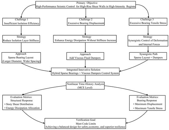
Figure 1.
Flowchart of the adopted research strategy for the hybrid seismic control system.
2. Project Overview
The project in Kashgar, Xinjiang Uygur Autonomous Region (seismic fortification intensity: 8; peak ground acceleration: 0.30 g) is classified as a Standard Fortification Class C structure. Site conditions correspond to Category II with Seismic Group 3 designation and a characteristic period of 0.45 s. Geotechnical investigation identified no near-fault conditions.
3. Seismic Isolation Design Scheme
3.1. Building 3 Apartment Overview
The seismic isolation layer of Building 3 is set at the top of the basement, with a layer height of 2 m. Below this layer are two basement levels (each with a floor-to-floor height of 3.5 m), while the superstructure comprises 20 stories at 3.3 m per floor. This reinforced concrete shear wall structure has a total height of 66 m, a plan width of 17.3 m, and a height-to-width ratio of 3.82. Conventional seismic design in high seismic intensity regions requires shear walls with excessive thickness, significantly reducing functional space efficiency. Additionally, conventional seismic design struggles to meet higher seismic performance objectives. Employing seismic isolation necessitates resolving three critical technical challenges: (1) low isolation efficiency in long-period structures requires extending the natural period from 1.1 s to at least 3.5 s [4]; (2) the stiffness–displacement trade-off necessitates reducing isolation layer stiffness to enhance seismic efficiency, yet substantial energy input during earthquakes increases the risks of displacement exceedance under MCE; (3) the high height-to-width ratio leads to significant overturning moments, and the tensile limit of rubber bearings is easily exceeded.
3.2. Comparative Analysis of Bearing Layout Schemes in Seismic Isolation Systems
Based on the positions of upper shear walls shown in Figure 2, the structure features six spans along the X-direction and adjustable column spacing along the Y-axis (2–4 spans per section, as shown in Figure 3), which results in three isolation bearing arrangement schemes.
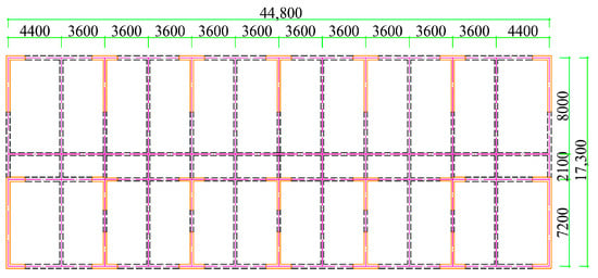
Figure 2.
Structural layout plan.
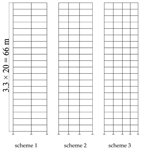
Figure 3.
Bearing arrangement scheme.
Detailed parameters for each scheme are tabulated in Table 2, with bearing layout drawings provided in Figure 4, Figure 5 and Figure 6. Scheme 1 serves as the baseline design, strictly adhering to the principle of installing bearings beneath all wall members; it deploys 35 isolation bearings (29 lead rubber bearings and 6 natural rubber bearings) with a diameter of 900 mm. Scheme 2 implements spatial density optimization, reducing the total number of bearings to 28 while uniformly increasing their diameter to 1000 mm (20 lead rubber bearings and 8 natural rubber bearings). The final scheme 3 further adopts the principle of enlarged diameter and spacing, utilizing only 21 isolation bearings with a diameter of 1100 mm (18 lead rubber bearings and 3 natural rubber bearings). This progression demonstrates a systematic increase in bearing diameter (900→1000→1100 mm) alongside a concurrent reduction in quantity (35→28→21).
Table 2.
Layout parameters for each design scheme.
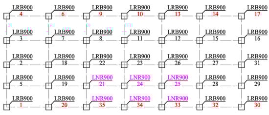
Figure 4.
Isolated bearing arrangement drawing (scheme 1).
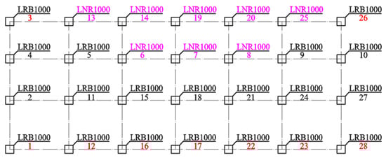
Figure 5.
Isolated bearing arrangement drawing (scheme 2).
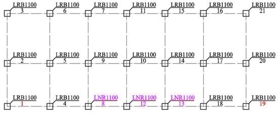
Figure 6.
Isolated bearing arrangement drawing (scheme 3).
The three isolation bearing arrangement schemes exhibit comparable yield forces at the isolation layer, with key computational results detailed in Table 3. Per Article 6.1.3 of the Standard for Seismic Isolation Design of Buildings [32], superstructures may adopt seismic measures corresponding to a one-degree reduction in seismic fortification intensity when the bottom shear ratio is ≤0.5. All schemes satisfy this criterion, with scheme 3 exhibiting optimal performance; its bottom shear ratio (0.309) is the lowest, indicating superior isolation efficiency. Verification under MCE reveals that (1) horizontal displacements all exceed the limits specified in GB/T 51408-2021 [32], with scheme 3 exhibiting the smallest exceedance; (2) tensile stresses all surpass the 1.0 MPa threshold (GB/T 51408-2021 [32]), peaking lowest in Scheme 3; (3) all schemes meet the overturning stability requirement, with scheme 3 achieving the highest safety margin.
Table 3.
Dynamic response comparison of schemes.
Scheme 3 employs a sparse isolator distribution strategy with increased diameters and spacings, achieving enhanced seismic performance through three optimized mechanisms. (1) Extended column spacings reduce structural stiffness, prolonging the isolation period to 3.991 s beyond dominant seismic frequencies and lowering the bottom shear ratio from 0.355 to 0.309, thereby reducing energy input. (2) Fewer bearings allow for larger diameters, increasing the second shape factor (S2 = D/tᵣ ≥ 5), which enhances compressive stability and raises the allowable displacement to 0.55D (605 mm when D = 1100 mm). Although isolation bearing displacement under MCE reached 641 mm, its 6% exceedance ratio outperforms that of other schemes. (3) Concentrated gravity loads from wider spacings increase the mean bearing pressure to 13.1 MPa (87.3% of the GB/T 51408-2021 limit [32]), creating vertical stress reserves that suppress tensile concentrations in edge isolators during overturning. This reduces the peak tensile stress from 3.10 MPa to 1.17 MPa and the number of isolators exceeding tensile limits from 9 to 2.
By sequentially optimizing the key design variables, low stiffness, high displacement tolerance, and improved vertical stress distribution, a design satisfying both safety and code requirements is established. Beyond the technical advantage of Scheme 3 are the economic merits. Based on an estimated typical unit cost of $1400 per bearing (including installation, inspection, and maintenance), and noting minimal price variation over the diameter range considered, the total cost of bearings for Scheme 3 is $29,400, a 40% savings over the $49,000 required for conventional Scheme 1. Moreover, the reduction in seismic forces allows downsizing structural components of the superstructure, such as the shear walls and a proportional reduction in reinforcement. Such design modification and material savings can reduce costs of superstructure construction by 1–5% in high-intensity zones, with even more material reduction possible in some cases, according to the literature [33,34].
As a result, Scheme 3 with a sparse layout with increased bearing diameter and spacing was tentatively selected as the preferred scheme for its outstanding isolation efficiency, improvement in displacement and tensile stress performance, and high economic efficiency. However, two key challenges that exist for all isolation schemes, but with the most robust baseline for resolution starting from scheme 3, are to be addressed: (1) increased requirements for the supporting transfer beams and columns below the isolation layer, and (2) the maximum bearing displacement and tensile stress under MCE are still over the code-specified upper limits. The solutions are illustrated in separate sections below.
3.3. Design and Verification of Critical Structural Components
The initial issue caused by a low-density isolator layout in scheme 3 is the larger span for the supporting transfer structure, which naturally increases the bending moment and shear force demands in the beams and columns beneath. To maintain global structural integrity, the design of these critical components was strengthened following performance-based criteria outlined in Article 4.7.2 of GB/T 51408-2021 [32].
To enhance their inherent load-bearing capacity, the cross-sectional dimensions of these components were increased. In addition, higher-strength materials—specifically C60 concrete and HRB500 steel reinforcement—were employed. These measures collectively provide the necessary stiffness and strength to withstand the demands imposed by the sparse isolator arrangement.
The capacity calculation of critical structural members under the MCE follows the conservative principle:
Here, S represents the internal force obtained from elastic response spectrum analysis, which yields a conservative estimate of demand as it excludes any plastic redistribution of internal forces. Rk represents the characteristic value of resistance, taken as the material’s lower yield point, while is the partial safety factor for resistance.
This verification framework overshoots the seismic demand and undershoots the capacity of the structure. This combined approach of design improvement and conservative verification can assure a large margin of conservatism and can guarantee the reliable performance of the sparse isolation system at all levels of seismic hazard.
3.4. Hybrid Seismic Isolation System with Energy-Dissipating Devices
Despite the significant isolation efficiency of Scheme 3 (with a bottom shear ratio of 0.309), the isolation bearing displacements (650 mm) and tensile stresses (1.17 MPa) under MCE both exceed the code-specified limits [32]. While using high-hardness elastomeric isolators or increasing bearing dimensions can reduce displacements, they increase structural stiffness—thereby amplifying seismic forces and further exacerbating the risk of excessive tensile stresses. Standalone tension-resistant devices mitigate tensile stresses but introduce complexities in construction: pre-installed components demanding high-precision joints, non-standardized commercial applications, poor compatibility with construction processes, cost increases (≥60%), and challenges in maintenance [26,27].
In contrast, viscous dampers added to the isolation layer efficiently dissipate seismic energy via velocity-dependent mechanisms. This approach can mitigate displacement and tensile exceedances during MCE, while avoiding the adverse effects of increased stiffness [28,29]. For instance, shake-table tests by Liu et al. (2018) demonstrated that viscous dampers can reduce isolator displacements by approximately 30% and decrease superstructure responses by dissipating input energy efficiently [29]. This mechanism aligns well with the dual objectives of displacement control and tensile stress reduction in the present system.
The dampers employed feature a fully sealed design, utilizing a highly stable silicone-based fluid that ensures resistance to aging, temperature fluctuations, and leakage. In accordance with product standards and field monitoring data, their design service life typically reaches or exceeds 50 years [35,36]. Routine maintenance is minimal, with inspections recommended only after extreme events [35]. This approach—validated in highly seismic regions (e.g., Yunnan [22], Shanxi Science City [37])—employs modular designs that enable rapid installation through supplemental connectors, while preserving the original bearing layouts, and results in significantly lower overall costs compared to standalone tension-resistant devices.
As illustrated in Figure 7, four damper sets per direction (X/Y) adhere to the principles of ‘uniformity, dispersion, and symmetry’, forming a hybrid seismic isolation system that combines seismic isolation and energy dissipation.

Figure 7.
Layout plan of dampers in seismic isolation layer.
Given the possible sensitivity of the system to damper properties, the parameters adopted were chosen following established engineering practice that the selected value should combine displacement control with isolated performance not overly compromised. For tall isolated buildings, the damping coefficient Cd is commonly specified in the range of 500–1200 kN/(m/s)α [30,35]. If Cd is too small, the isolation layer will not provide sufficient supplemental damping, and isolator displacement demands under the MCE will not be well controlled. Conversely, an overly large value of Cd has two major disadvantages, namely. (1) Structurally, large damping forces restrain the isolation layer and can introduce higher-mode responses of the superstructure. (2) Practically, when the resulting damper force exceeds about 1500 kN, the demand for strength, ductility, construction tolerance, etc., on some specific connections will be substantial, with the result that detail construction, cost, and detail failure risk will be greatly increased [29,34,37]. The chosen value (Cd = 800 kN/(m/s)α), therefore, represents a practical compromise that meets displacement limits without compromising isolation efficiency. The velocity exponent α, which is commonly taken in the range of 0.2–0.5, has only a comparatively minor influence on the overall response [16,17,29]. The selected value ensures consistent energy dissipation over a broad velocity range while avoiding excessive forces under large deformations.
4. Response Analysis Under Maximum Considered Earthquake
Building upon the established layout configuration with enlarged bearing diameters (1.1 m) and extended column spacings (8.0 m), this study employs nonlinear time history analyses to quantitatively compare key performance metrics between isolation-only and hybrid (isolators + viscous dampers) systems. The comparative analysis focuses on inter-story shear force distribution, energy dissipation allocation, isolator displacements, and tensile stresses under MCE. Statistical validation will quantify the resilience enhancement from supplemental viscous dampers, using structural performance data.
4.1. Cross-Platform Model Fidelity Verification: From YJK to ETABS
To ensure the accuracy of the time history analysis results, the conversion from YJK to the ETABS model should be verified. In this paper, the mass distribution and dynamic properties of the original design model and the converted analytical model were compared, respectively, to ensure the consistency of the two models.
The YJK model was designed strictly following the relevant design codes, considering the detailing provisions in automatic load combinations. Critical beams and columns in and above the isolation layer were specially designed to remain elastic under MCE conditions.
The isolation bearings in the ETABS model were simulated by paralleling the Rubber Isolator elements and the Gap elements at the same nodes, so as to precisely model the tension-compression asymmetric behavior. The Damper elements were used to simulate the viscous dampers.
The comparative results show that the mass deviation is less than 1% and the deviation of fundamental periods is within 3%, as shown in Table 4 and Table 5. Therefore, it is believed that the converted analytical model can fully reflect the structural system of the original model, which can be further used for nonlinear time history analysis.
Table 4.
Structural mass comparison.
Table 5.
Comparison of fundamental structural periods.
4.2. Selection of Ground Motion Time Histories for Maximum Considered Earthquakes
This study implements Clause 4.1.3 of GB/T 51436-2021 and Clause 5.1.2 of GB 50011-2010 for seismic input control [7,32]. Ground motion selection adheres to tripartite criteria—intensity, spectral characteristics, and duration. In line with these criteria, we selected five recorded ground motions and two artificially generated ground motions for time history analysis. Detailed information for each selected ground motion is presented in Table 6, and the time history curves are shown in Figure 8.
Table 6.
Ground Motion Record Information.
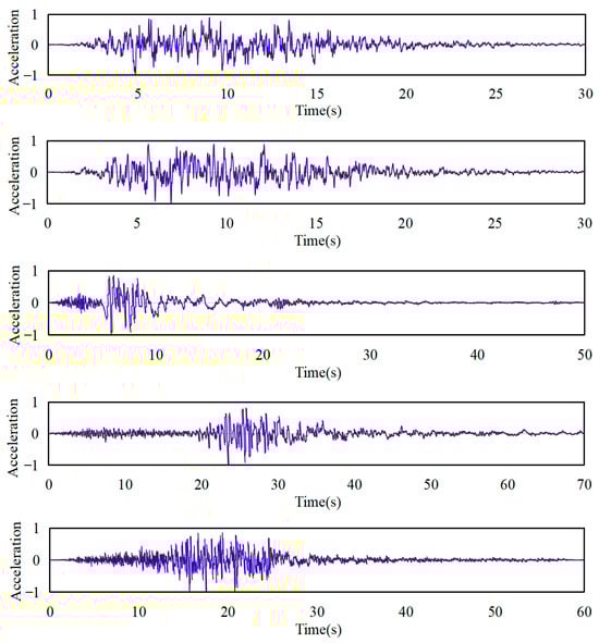
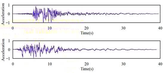
Figure 8.
Time history curves of normalized, dimensionless acceleration.
Structural base shears were calculated through time history analysis and response spectrum methods (Table 7). Results from individual waves exceeded 65% of response spectrum values, while the seven-wave ensemble average surpassed 80% of spectrum-based calculations. These outcomes meet the upper and lower base shear limits specified in GB 50011-2010 Clause 5.1.7 [7], validating the reliability and analytical validity of strength evaluation.
Table 7.
Base shear.
The effective duration of each wave—defined as the interval between the first and last 10% peak accelerations—ranges from 5.25 to 13.84 times the fundamental period (Table 8). This meets the 5–10 times requirement in GB 50011-2010 Clause 5.1.7 [7]. Sufficient duration coverage captures structural response and energy dissipation processes, preventing cumulative damage underestimation from short-duration ground motions.
Table 8.
Duration parameters of seven selected time history spectra.
Figure 9 and Table 9 compare the 7-wave average seismic influence coefficient curve with the code-specified response spectrum at the fundamental periods. The maximum deviation at the control period is 10.7%, which is well below the 20% limit specified in GB 50011-2010 Clause 5.1.7 [7]. This spectral consistency between input motions and design spectrum ensures effective matching of seismic inputs to structural dynamic characteristics.
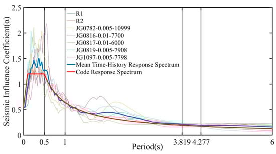
Figure 9.
Comparison of seven time history response spectra and code response spectrum (αmax = 1.2, Tg = 0.50 s).
Table 9.
Comparison of influence coefficients for seven time history response spectra and code response spectrum (Tg = 0.50 s).
In summary, the seven selected ground motions satisfy the requirements of GB 50011-2010 [7] regarding intensity, duration, and spectral matching. Such compliance establishes a reliable basis for subsequent time history analysis.
4.3. Story Shear Analysis
Story shear force acts as a key parameter characterizing the seismic response of structures. Consequently, this section presents a comparative analysis of the story shear forces before and after installation of viscous dampers within the isolation layer, under MCE. Figure 10 presents the average story shear forces for both structural configurations under seven seismic ground motions. The results indicate that installing dampers significantly reduces story shear forces in floors below the 15th. Notably, the reduction magnitude increases with proximity to the isolation layer. Specifically, the shear forces within the isolation layer itself were reduced by 17.3% in the X-direction and 17.8% in the Y-direction. The underlying mechanisms can be attributed to two factors. (1) Viscous dampers effectively dissipate a significant portion of the seismic input energy as heat, thereby reducing the inertial forces transferred to the superstructure. Since the dampers act directly within the isolation layer, the shear force reduction is most pronounced there. (2) The phase difference effect alleviates the peak superposition of shear forces. The total shear force in the isolation layer consists of the elastic force from the laminated rubber bearings and the damping force from the viscous dampers. Owing to the phase difference in their response characteristics—the bearing elastic force is in phase with displacement, while the viscous damper force is in phase with velocity—their peak values do not coincide. Consequently, the maximum total isolation layer shear force is less than the arithmetic sum of the respective peak forces from the bearings and dampers.
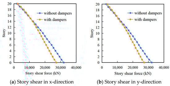
Figure 10.
Comparison of story shear force.
The installation of viscous dampers in the isolation layer increased story shear forces in floors above the 15th level by 3.6–20.5% (X-direction) and 3.8–21.0% (Y-direction). This phenomenon arises because the dampers effectively dissipate seismic energy via velocity-dependent forces within the isolation layer, reducing inertial forces transferred to the superstructure. However, this damping mechanism excites higher-order modes within the superstructure, thereby inducing a redistribution of shear forces in the upper stories [30].
4.4. Superstructure Response: Comparison with Conventional Damage Mechanisms and Performance Verification
To thoroughly investigate the behavior of the superstructure shear walls within the isolation system, this section compares the findings of this study with the damage mechanisms of conventional shear walls and systematically demonstrates their performance.
Numerous studies have illuminated the nonlinear behavior and damage mechanisms of conventional coupled shear walls subjected to strong earthquakes. As reported by Jafari A and Beheshti M [38,39], such walls commonly display significant curvature concentration and material damage within plastic hinge zones, with the degree of damage largely determined by axial stress ratio and coupling ratio. In contrast, the results of the elastoplastic time history analysis in this study suggest that all superstructure shear walls and coupling beams in the isolated structure remain completely elastic under MCE; in other words, no plastic hinge forms. This finding is consistent with extensive research and engineering practice that the use of isolation technology typically results in zero or only a limited amount of damage in the superstructure even when subjected to strong seismic events [40,41]. This finding exemplifies the most fundamental philosophical difference between isolation technology and the conventional seismic design approaches; while the former is predicated on the notion that the seismic demand on the superstructure can be drastically reduced via the concentration of deformation and energy dissipation in the isolation layer, thus avoiding nonlinear damage in the superstructure, the latter is predicated on the notion that seismic energy can be dissipated by allowing and controlling plasticity in key superstructure members.
The realization and verification of this elastic behavior is supported by several integral mechanisms. First and foremost, in the isolation layer, the dominant portion of earthquake energy is filtered and dissipated. As revealed by the analysis results, the base shear is reduced by approximately 70% compared to a traditional anti-seismic structure. This large reduction in base shear is a prerequisite for achieving the elastic response of the superstructure. Furthermore, the shear force amplification observed in floors above Level 15 is a well-documented high-order mode response in isolated structures. In order to engineer a practical solution, a “group-envelope” design principle is used in which Level 15–20 is considered as a separate design group and designed using identical cross-sections and reinforcement based on envelope values of the internal forces produced by the most critical load cases. Last but not least, the stringent requirements of the seismic code on wall axial compression ratio, boundary elements, and minimum reinforcement ratio provide a substantial reserve of strength and ductility, which serves as an “insurance policy” for achieving the elastic result.
To verify the elastic response of the superstructure under severe seismic loading, the structural components above the 15th story were assessed, with a focus on the most critically stressed shear wall (Wall-A) and a representative coupling beam. Given the envelope design approach adopted for this segment, these components are deemed to provide a conservative evaluation of the overall performance.
- Shear Wall Capacity Check
The shear wall, with a cross-section of 250 mm × 2100 mm, was constructed from C40 concrete and HRB400 reinforcement. Its nominal shear capacity, RWK, is calculated as
where is the characteristic tensile strength of concrete, is the wall thickness, hw0 is the effective wall length, and is the total area of horizontally distributed reinforcement within spacing s. Substitution of the material properties and geometric parameters yields
Under the MCE, the calculated shear force in the wall is 3084 kN. Since this demand is less than the shear capacity (), the wall is confirmed to remain within its elastic range.
- Coupling Beam Capacity Check
The coupling beam, with a cross-section of 250 mm × 500 mm and made of the same materials, has a nominal shear capacity given by
where denotes the beam width, is the effective depth, and is the total area of shear reinforcement within spacing s. The resulting capacity is
Under the MCE, the shear force in the beam reached 1139 kN, which is also below its capacity (), verifying that the coupling beam behaves elastically under the MCE-level demand.
In summary, through comparison with conventional systems and detailed quantitative verification, this study demonstrates that hybrid isolation technology effectively enables superstructure shear walls to avoid traditional nonlinear damage mechanisms. The shear amplification in upper stories is a localized phenomenon adequately addressed by the “group-envelope” design strategy. Component-level checks confirm the superstructure’s macroscopic elasticity under rare earthquakes, fully underscoring the advantage of isolation systems in achieving superior seismic performance objectives.
4.5. Energy Response Analysis
The energy balance equation for a hybrid seismic isolation system with dampers can be written as Ein = Ebearing + Edamp + Eh + Ec + Ek. Here, Ein denotes the total seismic input energy, Ebearing represents the energy dissipated by isolation bearings, Edamp quantifies the energy dissipated by dampers, Eh signifies the energy dissipation within the superstructure, Ec describes the kinetic energy of the superstructure, and Ek indicates the elastic potential energy stored in the superstructure. Cumulative energy histories for isolation-only systems and hybrid isolation systems (isolators + viscous dampers) under MCE were extracted. Representative results for the T3 ground motion are presented in Figure 11.
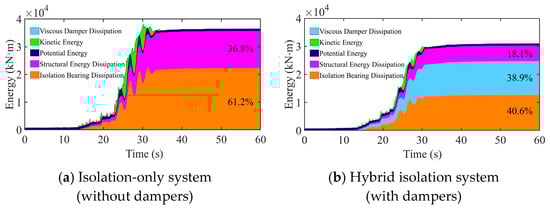
Figure 11.
Cumulative energy profile.
Comparative analysis reveals distinct energy dissipation mechanisms between systems. For the isolation-only system without dampers, seismic input energy is primarily allocated between isolation bearing dissipation (61.2%) and superstructure hysteretic dissipation (36.8%). After installing viscous dampers, energy dissipation is dominated by three mechanisms: isolation bearings (40.6%), viscous dampers (38.9%), and superstructure hysteresis (18.1%).
Viscous fluid dampers fundamentally restructure seismic energy pathways through efficient energy dissipation. These dampers utilize velocity-dependent forces to efficiently dissipate energy in the isolation layer at peak displacement/velocity regions, directly accounting for roughly 38.9% of the total input energy. Consequently, the energy dissipation proportion of isolation bearings decreases from 61.2% to 40.6%, thereby substantially reducing their deformation demands. Such a reduction mitigates tensile stresses in the bearings and prevents damage caused by excessive displacements. Concurrently, dampers limit energy transfer to the superstructure, lowering its hysteretic dissipation to 18.1%. This effectively controls the accumulation of plastic deformation and enhances seismic performance by mitigating structural damage.
To further elucidate the interaction mechanism between the dampers and isolation bearings, a simplified analytical model is established. The superstructure is idealized as a rigid mass m, and the isolation layer consists of nonlinear isolation bearings in parallel with equivalent linear viscous dampers having a damping coefficient cd. The equation of motion is given by
where , , represent the displacement, velocity, and acceleration of the isolation layer, respectively; is the ground acceleration; and Fbearing denotes the restoring force of the bearing, which exhibits hysteretic characteristics.
Gaining insight into the coupling between the damper and bearing is all about the phase relationship of the mechanical responses of the two devices. The damping force is in proportion to velocity, leading displacement by 90° in phase. But the restoring force of the isolation bearing Fbearing, mainly displacement-dependent, will, under nonlinear hysteretic conditions, introduce more phase lag.
When the isolation layer moves, the damping force reaches its peak while the velocity is highest (i.e., the displacement is close to zero). This is precisely where the instantaneous energy dissipation rate, as defined by , peaks. This is a physical manifestation of the damper’s ability to effectively intercept and dissipate kinetic energy, therefore reducing the structural dynamic responses. Additionally, this peak dissipation at the right time indirectly decreases the energy demand that would otherwise cause large deformation of the isolation bearings, leading to a much smaller hysteretic loop area (i.e., Ebearing). Conversely, near peak displacement (where velocity tends to zero), the damper’s influence diminishes, and the bearing’s stiffness dominates, managing the potential energy through recentering.
The flowchart in Figure 12 summarizes this phase-based complementary mechanism; dampers primarily dissipate kinetic energy, while bearings manage potential energy. This mechanism is highly “active” in redistributing the energy (Figure 11), with a total of about 38.9% of input energy being dissipated by the Viscous dampers, thus greatly reducing the energy dissipation by bearings, while at the same time more effectively suppressing the energy input to the superstructure, therefore greatly improving the structural safety.
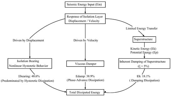
Figure 12.
Schematic of energy transmission paths in the hybrid isolation system.
In summary, this analysis demonstrates that the hybrid system’s performance arises from a phase-driven collaboration between dampers and bearings. This cooperative mechanism reallocates energy dissipation efficiently and offers a clear theoretical basis for improved seismic design.
4.6. Analysis of Displacement and Tensile Stress in Seismic Isolation Bearings
Under MCE, excessive lateral displacement and localized tensile stress in seismic isolation bearings pose critical safety risks to structures. The Standard [32] specifies that bearing displacement must not exceed 0.55 times the effective diameter and 3.0 times the total rubber thickness, while limiting tensile stress to ≤1 MPa to prevent rubber layer tearing and superstructure overturning. Adding viscous dampers alleviates these issues by altering energy dissipation mechanisms. This section uses time history analysis to compare displacement and tensile stress responses between the hybrid isolation system (isolators + viscous dampers) and the isolation-only system. It quantitatively evaluates the efficacy of viscous dampers in suppressing these critical parameters. The load combinations prescribed by the code [42] and employed in this analysis deserve particular note. For displacement, the combination 1.0 × dead load + 0.5 × live load + 1.0 × horizontal earthquake captures the maximum lateral deformation. For tensile stress verification, the combination 1.0 × dead load—1.0 × horizontal earthquake—0.5 × vertical earthquake is used to produce the most critical uplift effect, where live load is omitted as it is favorable and vertical earthquake is considered in its adverse direction. This philosophy of applying distinct combinations based on clear physical objectives and engineering judgment aligns fundamentally with the principles of major international standards. The requirement for multiple load cases addressing different limit states in ASCE/SEI 7-22, the necessity to consider worst-case scenarios in FEMA P-58 performance assessment, and the emphasis on representing true seismic action mechanisms in ISO 3010 all share this common logical foundation [8,15,43]. This demonstrates that the core analytical framework of this study is consistent with internationally accepted seismic design practice.
4.6.1. Maximum Displacement of Seismic Isolation Bearings
Table 10 shows that installing four viscous dampers along each orthogonal direction (X and Y) of the isolation layer significantly reduces bearing displacements. Based on the average of seven ground motions, displacements decreased by 25% in the X-direction (from 644 mm to 485 mm) and 24% in the Y-direction (from 641 mm to 484 mm). Post-installation displacements fall below 605 mm (0.55D) and 606 mm (3Tr), with D = 1100 mm (bearing diameter) and Tr = 202 mm (total rubber thickness). These values meet the requirements specified in Standard [32]. Additionally, this successful control exhibits consistent behavior with the objectives of international design guidelines. The deterministic displacement limit in the Chinese code (min (0.55D, 3Tr)) and the displacement demand calculation (DT = IM × DTD) in ASCE/SEI 7-22 Chapter 17 have the same basic safety objective: to ensure isolator stability and recentering capability under MCE demand [15]. When the mean displacement is controlled to about 80% of the 0.55D, it provides a safety margin against instability. From the perspective of performance-based design, although FEMA P-58 does not prescribe a deterministic displacement limit, it does consider isolator instability due to large displacement as a potential collapse mode [8]. The drastic reduction in displacement achieved in this case directly reduces the probability of this type of consequences-rich failure mode in a FEMA P-58 analysis, and thereby reduces repair costs and functional downtime. The basic safety purposes described in ISO 3010 are also achieved by this practical displacement control [43].
Table 10.
Maximum displacement of seismic isolation bearings.
Viscous dampers generate velocity-dependent forces, which efficiently dissipate energy within the isolation layer at regions of peak displacement or velocity, accounting for up to 39% of total input energy. This mechanism directly reduces the deformation demands placed on the bearings. Concurrently, peak damping forces occur at displacement zero points [46] while maximum isolator internal forces develop at displacement extremes. The resulting phase difference prevents the superposition of deformations, thereby further suppressing displacement amplitudes.
4.6.2. Maximum Tensile Stress of Seismic Isolation Bearings
Table 11 shows that under MCE conditions, installing viscous dampers reduced the number of tensioned bearings from 9 to 7, with Bearings #3 and #21 shifted from tension to compression. Bearings exhibited significant tensile stress reductions (54–78%). Among these, corner bearings #1 and #19—which had the highest tensile stress among all supports—decreased from 1.17 MPa to 0.54 MPa, falling below the 1 MPa threshold. The realized stress of 0.54 MPa goes beyond merely meeting code-specified prescriptive national criteria. It also achieves compliance with performance-based international safety frameworks. ASCE/SEI 7-22 does not require any generic limit for tensile stress in the isolator and ensures safety by requiring rigorous prototype testing for isolators experiencing extreme deformations [15]. The high margin of stress below the code limit assures conformance to such international testing requirements. Within the FEMA P-58 framework, isolator tensile failure is classified as a component-level damage state affecting reparability [8]. Maintaining stresses at a low fraction of the material’s capacity thus reduces the probability of this damage state, enhancing the system’s seismic resilience and functional recovery potential.
Table 11.
Maximum tensile stress of seismic isolation bearings.
This mitigation stems primarily from dampers sharing shear forces, which reduce bending moments on corner bearings to alleviate critical tensile stresses. Viscous dampers control bearing displacements to indirectly keep tensile stresses within safe limits, fundamentally avoiding the risk of rubber layer tearing.
The above description of energy redistribution and reduction in key response parameters is consistent with those due to the mechanisms at work in hybrid isolation systems utilizing viscous dampers observed in experimental studies [29,47]. This study further validates the notion that damper addition to the stiffness-optimized isolation layer can indeed exploit the inherent advantage of such hybrid isolation systems. The approach successfully mitigates large displacements and high tensile stresses in tall structures, demonstrating a viable design strategy.
4.6.3. Assessment of Record-to-Record Variability
A rigorous evaluation of seismic performance based on nonlinear time history analysis must explicitly account for the inherent uncertainty stemming from record-to-record (RTR) variability. The standard deviation and coefficient of variation (CoV) shown in Table 10 and Table 11 represent the observed dispersion for the governing response measures, that is, bearing displacement and tensile stress. This observed dispersion is largely attributed to the differing spectral content of the input ground motions, especially in the long-period range that dominates the response of the long-isolated system (T ≈ 4.3 s). The variability in frequency content, duration, and the presence of velocity pulses among the suite of selected records imparts differing energy input and phasing interactions with the hybrid isolation system. This is reflected in the observed record-to-record variability of critical engineering demands.
This variability holds significant importance in engineering. The displacement CoV of 0.18–0.22 observed here is consistent with the 0.1–0.25 range in common performance assessment guidelines, such as FEMA P-58 [8] for isolated structures subjected to extreme ground motions, verifying the expected demand scatter. Of particular interest, while the hybrid system drastically reduces the average displacement, the CoV is comparable. This suggests that the benefit of the dampers is similar for all records but the magnitude is ground motion dependent.
Crucially, the system’s robustness is demonstrated not by eliminating variability, but by shifting the entire response distribution into a safe domain. The hybrid configuration ensures that the mean responses and the vast majority of individual record outcomes comply with code limits, a marked improvement over an isolation-only system where exceedances were frequent. This translates to a much more predictable outcome and a greater safety margin.
5. Conclusions
Taking a high-rise shear wall structure as a case study, this paper presents an economically feasible hybrid seismic isolation system. This was achieved through comparison and optimization of bearing layout schemes within the isolation layer, followed by the optimized design incorporating viscous dampers directly into the isolation layer. The key findings are as follows:
- (1)
- Comparison of bearing layout schemes demonstrated that a sparse distribution strategy (increasing bearing diameter and spacing) offers superior performance in optimizing the bottom shear ratio and controlling key response indicators (displacement, tensile stress) under the MCE.
- (2)
- Adding viscous dampers to the isolation layer significantly altered the distribution of structural dynamic responses. Story shear forces decreased variably across Floors 1–15 (with a peak reduction of ~17% at the isolation layer) but increased above Floor 15 due to higher-mode effects. Concurrently, the energy dissipation ratios of isolation bearings decreased from 61.2% to 40.6%, and those of the superstructure from 36.8% to 18.1%, which effectively mitigates cumulative plastic damage in both components.
- (3)
- The hybrid seismic isolation system effectively resolved the issues of excessive bearing displacement and tensile stress under the MCE. Installing dampers reduced bearing displacement from 644 mm to 485 mm and tensile stress from 1.17 MPa to 0.54 MPa, thus meeting the code-specified limit requirements.
This study’s primary significance lies in its proposal of a holistic seismic isolation system solution for high-rise structures in highly seismic regions. It effectively addresses critical technical challenges, including optimizing the bottom shear ratio and controlling bearing displacement/tensile stress under MCE. A limitation, however, is the lack of a systematic sensitivity analysis to quantify the influence of uncertainties—particularly in viscous damper properties, along with material characteristics, ground motion variability, and construction tolerances—on overall system performance. Future work will optimize damper layout parameters (quantity, placement) and model parameters (damping coefficient, velocity exponent, maximum damping force). It will evaluate their synergistic effects on the overall seismic isolation system and superstructure performance, aiming to develop more refined design strategies for similar engineering applications.
Author Contributions
Methodology, G.S. and W.S.; Validation, W.S.; Resources, W.S.; Writing—original draft, T.L.; Writing—review & editing, T.L. and R.L.; Project administration, W.S.; Funding acquisition, R.L. All authors have read and agreed to the published version of the manuscript.
Funding
This research was funded by the Introduction of Talent Research Initiation Fund of Kashi University (No. GCC2024ZK-018), the Open project of Xinjiang Key Laboratory of Engineering Materials and Structural Safety (No. XKLEMSS2025B06) and the College Students’ Innovation and Entrepreneurship Training Program (No. 202510763147). The authors are very grateful for this support. Any opinions, findings, and conclusions or recommendations expressed in this material are those of the authors and do not necessarily reflect the views of the fundings.
Data Availability Statement
The original contributions presented in the study are included in the article, further inquiries can be directed to the corresponding author.
Conflicts of Interest
Author Wujie Sun was employed by the company Zhonglu Construction (Yunnan) Company Limited. The remaining authors declare that the research was conducted in the absence of any commercial or financial relationships that could be construed as a potential conflict of interest.
References
- Xiang, N.L.; Li, J.Z. Experimental and numerical study on seismic sliding mechanism of laminated-rubber bearings. Eng. Struct. 2017, 141, 159–174. [Google Scholar] [CrossRef]
- Derham, C.J.; Kelly, J.M.; Thomas, A.G. Nonlinear natural rubber bearings for seismic isolation. Nucl. Eng. Des. 1985, 84, 417–428. [Google Scholar] [CrossRef]
- Naeim, F.; Kelly, J.M. Design of Seismic Isolated Structures: From Theory to Practice; John Wiley & Sons: Hoboken, NJ, USA, 1999. [Google Scholar]
- Xin, L.; Yang, Q.; Wang, H.Q.; Jing, G.; Zou, S. Base isolation design and analysis of high-rise frame-shear wall structure in a high intensity area. Build. Struct. 2021, 51, 8–13. (In Chinese) [Google Scholar] [CrossRef]
- Li, X.J. Adjustment of seismic ground motion parameters considering site effects in seismic zonation map. Chin. J. Geotech. Eng. 2013, 35, 21–29. (In Chinese) [Google Scholar]
- Guan, Q.S.; Song, T.S.; Zhang, L.F.; Wang, Y.; Alata. Seismic Isolation Design of Yu xi Public Rental Housing Structures. Prog. Steel Build. Struct. 2017, 19, 87–96. (In Chinese) [Google Scholar] [CrossRef]
- GB 50011-2010; Code for Seismic Design of Buildings. Ministry of Housing and Urban-Rural Development of China: Beijing, China, 2010.
- Federal Emergency Management Agency (FEMA). Seismic Performance Assessment of Buildings Volume 1—Methodology; Rep. No. FEMA P-58-1; Federal Emergency Management Agency: Washington, DC, USA, 2012.
- Zhou, J.J. Implementing the Regulations of Administration of Seismic Management of Construction Projects to Maintain Normal Functionality of Buildings. Stand. Eng. Constr. 2023, 44, 66–68. (In Chinese) [Google Scholar] [CrossRef]
- Zhai, C.H.; Song, Z.R.; Xie, L.L. A approach for seismic resilience design of buildings. Build. Struct. 2025, 46, 124–133. [Google Scholar] [CrossRef]
- Almufti, I.; Willford, M. REDi™ Rating System: Resilience-Based Earthquake Design Initiative for the Next Generation of Buildings; Arup Co.: London, UK, 2013. [Google Scholar]
- Wada, A.; Kani, N.; Hirano, S.; Kamikouchi, H.; Kimura, M. Seismic isolated structures applied to from detached houses to high-rise apartments in Japan. In Proceedings of the 5th International Conference on Urban Earthquake Engineering, Tokyo, Japan, 4–5 March 2008. [Google Scholar]
- Becker, T.C.; Yamamoto, S.; Hamaguchi, H.; Higashino, M.; Nakashima, M. Application of isolation to high-rise buildings: A Japanese design case study through a US design code lens. Earthq. Spectra 2015, 31, 1451–1470. [Google Scholar] [CrossRef]
- Takayama, M. Development and application of seismic isolation and response control of buildings in Japan. In Proceedings of the New Zealand Society for Earthquake Engineering Annual Conference, Wellington, New Zealand, 27–29 April 2017. [Google Scholar]
- ASCE/SEI 7-22; Minimum Design Loads and Associated Criteria for Buildings and Other Structures. American Society of Civil Engineers: Reston, VA, USA, 2022.
- Yenidogan, C. Earthquake-resilient design of seismically isolated buildings: A review of technology. Vibration 2021, 4, 602–647. [Google Scholar] [CrossRef]
- Avinash, G.C.; Lingeshwaran, N. Review on base and inter storey seismic isolation systems for high rise buildings. Res. Eng. Struct. Mater. 2024, 11, 231–276. [Google Scholar] [CrossRef]
- Losanno, D.; Sierra, I.E.M.; Spizzuoco, M.; Marulanda, J.; Thomson, P. Experimental assessment and analytical modeling of novel fiber-reinforced isolators in unbounded configuration. Compos. Struct. 2019, 212, 66–82. [Google Scholar] [CrossRef]
- IS 1893-6:2022; Criteria for Earthquake Resistant Design of Structures: Part 6 Base Isolated Buildings. Bureau of Indian Standards: New Delhi, India, 2022.
- Salunkhe, V.A.; Jangid, R.S.; Ranjan, R. Seismic Soil–Structure Interaction Analysis of Base Isolated Nuclear Building of Indian Pressurized Heavy Water Reactor Subjected to Coherent Ground Motion. Pract. Period. Struct. Des. Constr. 2024, 29, 04024054. [Google Scholar] [CrossRef]
- Sivasubramanian, P.; Manimaran, M.; Vijay, U.P. Implementation of base-isolation technique in the design of mega hospital building. In International Conference on Cement and Building Koncrete for a Sustainable and Resilient Infrastructure; Springer: Singapore, 2024; pp. 299–313. [Google Scholar]
- He, Y.M. Dynamic Field Test for A Base-Isolated High-Rise Steel Building Structure. Ph.D. Thesis, Institute of Engineering Mechanics, China Earthquake Administration, Harbin, China, 2013. [Google Scholar]
- Li, Y.S.; Xiao, C.Z.; Xue, Y.T.; Jin, L.F.; Zeng, D. Seismic isolation design of a high-rise shear-wall residential building. Build. Struct. 2014, 44, 26–31+25. (In Chinese) [Google Scholar] [CrossRef]
- Cardone, D.; Palermo, G.; Dolce, M. Direct displacement-based design of buildings with different seismic isolation systems. J. Earthq. Eng. 2010, 14, 163–191. [Google Scholar] [CrossRef]
- Deringöl, A.H.; Güneyisi, E.M. Effect of using high damping rubber bearings for seismic isolation of the buildings. Int. J. Steel Struct. 2021, 21, 1698–1722. [Google Scholar] [CrossRef]
- Nagarajaiah, S.; Reinhorn, A.M.; Constantinou, M.C. Experimental study of sliding isolated structures with uplift restraint. J. Struct. Eng. 1992, 118, 1666–1682. [Google Scholar] [CrossRef]
- Hu, K.; Zhou, Y.; Jiang, L.; Chen, P.; Qu, G. A mechanical tension-resistant device for lead rubber bearings. Eng. Struct. 2017, 152, 238–250. [Google Scholar] [CrossRef]
- Kelly, J.M. The role of damping in seismic isolation. Earthq. Eng. Struct. Dyn. 1999, 28, 3–20. [Google Scholar] [CrossRef]
- Liu, Y.; Wu, J.; Donà, M. Effectiveness of fluid-viscous dampers for improved seismic performance of inter-storey isolated buildings. Eng. Struct. 2018, 169, 276–292. [Google Scholar] [CrossRef]
- Avossa, A.M.; Pianese, G. Damping Effect on the Seismic Response of Base-Isolated Structures with LRB Devices. Ing. Sismica 2017, 34, 3–30. [Google Scholar]
- Mayes, R.L.; Jones, L.R.; Kelly, T.E. The economics of seismic isolation in buildings. Earthq. Spectra 1990, 6, 245–263. [Google Scholar] [CrossRef]
- GB/T 51408-2021; Standard for Seismic Isolation Design of Building. Ministry of Housing and Urban-Rural Development of China: Beijing, China, 2021.
- Bolisetti, C.; Coleman, J.L.; Hoffman, W.M.; Whittaker, A.; Parsi, S.S.; Redd, J.; Cohen, M.; Kramer, K.; Kirchman, P.; Bowers, H.; et al. Seismic Isolation of Major Advanced Reactor Systems for Economic Improvement and Safety Assurance; Idaho National Lab. (INL): Idaho Falls, ID, USA, 2020.
- Duan, B.Y.; Zhu, J. Integrated optimization of isolated structures throughout their lifetime. J. Shanghai Univ. (Nat. Sci. Ed.) 2023, 29, 1053–1067. [Google Scholar]
- Katsimpini, P.; Papagiannopoulos, G.; Hatzigeorgiou, G. A Thorough Examination of Innovative Supplementary Dampers Aimed at Enhancing the Seismic Behavior of Structural Systems. Appl. Sci. 2025, 15, 1226. [Google Scholar] [CrossRef]
- GB/T 20688.4-2023; Rubber Bearings—Part 4: Plain Rubber Bearings. China Standard Press: Beijing, China, 2023.
- Cheng, X.P.; Li, W.; Lai, Z.Y. Application of Isolation Bearings and Viscous Dampers in Shanxi Science and Technology Innovation City. In Proceedings of the 12th China-Japan Conference on Building Structures, Chongqing, China, 23 September 2017; pp. 1–12. [Google Scholar]
- Jafari, A.; Beheshti, M.; Shahmansouri, A.A.; Bengary, H.A. Plastic hinge length for coupled and hybrid-coupled shear walls. Steel Compos. Struct. 2022, 367–383. [Google Scholar]
- Jafari, A.; Beheshti, M.; Shahmansouri, A.A.; Bengary, H.A. Cyclic response and damage status of coupled and hybrid-coupled shear walls. Structures 2024, 61, 106010. [Google Scholar] [CrossRef]
- Zhang, R.; Li, A. Experimental study on the performance of damaged precast shear wall structures after base isolation. Eng. Struct. 2021, 228, 111553. [Google Scholar] [CrossRef]
- Ferraioli, M.; Mandara, A. Base isolation for seismic retrofitting of a multiple building structure: Evaluation of equivalent linearization method. Math. Probl. Eng. 2016, 2016, 8934196. [Google Scholar] [CrossRef]
- GB 50009-2012; Load Code for the Design of Building Structures. Ministry of Housing and Urban-Rural Development of China: Beijing, China, 2012.
- ISO 3010:2017; Basis for Design of Structures—Seismic Actions on Structures. International Organization for Standardization: Geneva, Switzerland, 2017.
- Amiri, G.G.; Namiranian, P.; Amiri, M.S. Seismic response of triple friction pendulum bearing under near-fault ground motions. Int. J. Struct. Stab. Dyn. 2016, 16, 1550021. [Google Scholar] [CrossRef]
- Yang, Z.Y.; Xiao, L.; Huang, J.; Tian, J. Relationship between seismic responses of building structures and displacement spectra of ground motions under rare earthquakes. Earthq. Eng. Eng. Dyn. 2010, 30, 29–36. [Google Scholar] [CrossRef]
- Feng, D.; Wang, J. Seismic control of a self-anchored suspension bridge using fluid viscous dampers. Int. J. Struct. Stab. Dyn. 2021, 21, 2150025. [Google Scholar] [CrossRef]
- Zhang, S.; Wu, Y.; Yang, K.; Wang, J. Multi-Stage Vibration Control Mechanism and Experimental Effectiveness of Viscous Damper with Overload Protector. J. Vis. Exp. JoVE 2025, 223. [Google Scholar] [CrossRef]
Disclaimer/Publisher’s Note: The statements, opinions and data contained in all publications are solely those of the individual author(s) and contributor(s) and not of MDPI and/or the editor(s). MDPI and/or the editor(s) disclaim responsibility for any injury to people or property resulting from any ideas, methods, instructions or products referred to in the content. |
© 2026 by the authors. Licensee MDPI, Basel, Switzerland. This article is an open access article distributed under the terms and conditions of the Creative Commons Attribution (CC BY) license.