Abstract
A numerical model based on the heuristic molecule (HM) concept is proposed to evaluate the in-plane and Coulomb-like shear behavior of masonry panels. The model extends the well-established Rigid-Body-Spring Model (RBSM), which demonstrated good effectiveness in the seismic analysis of masonry structures. The proposed advancement introduces two diagonal bond-springs specifically designed to improve the representation of shear damage mechanisms. The performance of this enhanced formulation was assessed through numerical simulations of small-scale shear panel tests experimentally tested in the literature under varying levels of pre-compression, for which dedicated nonlinear stress–strain laws for axial, shear, and diagonal bond-springs were implemented. The results indicate that the proposed model provides an accurate description of the observed behavior while maintaining a limited number of degrees of freedom, thus ensuring computational efficiency. These promising outcomes highlight the model’s potential for future applications, including large-scale dynamic analyses.
Keywords:
masonry; shear; heuristic molecule; RBSM; texture-bond; orthotropy; interlocking; Coulomb-like behavior 1. Introduction
The solid mechanics behavior of a masonry panel depends on the characteristics of the heterogeneous construction materials and the shape and arrangement of blocks and mortar joints. The constituent elements generally have negligible tensile strength, good compressive strength, and tend to collapse in a quasi-brittle manner [1]. This causes masonry walls to exhibit a markedly nonlinear response, characterized by a progressive decay of stiffness and strength, also related to energy dissipation [2,3]. The arrangement of blocks and joints in predominantly horizontal layers induces interlocking phenomena in the masonry composite and, especially in the post-elastic range, a significant orthotropy of the shear response with a Coulomb-like behavior that is markedly different for horizontal mortar joints, which tend to be continuous, compared to vertical ones.
This manuscript contributes to this specific aspect, adopting the Rigid Body-Spring approach, RBSM, which is here based on the concept of heuristic molecules, HM, recently formalized by [4]. By following the general idea of the RBSM-HM approach, we implemented a formulation based on the introduction of additional diagonal springs that allow us to analytically define the orthotropic post-elastic response and shear damage by a combination of internal actions at the elementary cell level (i.e., by means of the heuristic molecule meso-scale scheme), including micro-polar effects. The damage behavior of masonry panels subjected to combined shear and vertical compression is one of the most challenging aspects to model since load-bearing capacity is strongly related to the geometry of the masonry texture. The presence of a moderate vertical load generally tends to enhance shear performance, and the shape and arrangement of the blocks can provide a significant interlocking contribution. Early in-plane RBSM models proposed for masonry [5,6,7] clearly distinguished between behavior dominated by axial actions and those governed primarily by angular deformation and proved to be effective in situations where the vertical load was either very high or low. For intermediate conditions, we investigated the implementation of additional diagonal bond-springs that interact with the bond-springs originally assigned to shear. The manuscript is structured as follows: Section 2 provides an overview of existing strategies for modeling the in-plane behavior of masonry, highlighting limitations and challenges. Section 3 presents the experimental case studies adopted to validate the proposed approach, consisting of six 1:4 scale masonry panels subjected to a lateral load and different pre-compression loads [8]. Section 4 introduces the proposed model, describing the essential theoretical aspects, together with the geometric characteristics of the examples implemented. Section 5 describes the strategies adopted for defining the elastic and post-elastic characteristics of bond-springs. Section 6 describes the results obtained by the numerical simulations. Finally, Section 7 presents some final remarks and considerations on future developments of the work.
2. Modeling the In-Plane Behavior of Masonry Panels: From Micro to Macro
Masonry is a heterogeneous composite material with a macro-scale elastic and post-elastic behavior that depends on the geometry and arrangement of blocks and joints. The micro-structure of masonry composites leads to phenomena that should be considered, especially in the nonlinear analysis, such as orthotropy, interlocking, shear strength orthotropy and Coulomb-like behavior. The modeling strategies frequently adopted for masonry can be classified according to the scale of analysis [9,10,11,12,13,14,15,16,17,18,19,20,21].
Micro-scale approaches involve numerical modeling of the masonry composite at the scale of its constituent elements. They include strategies based on finite element method (FEM) and discrete element method (DEM) [22]. FE models often involve the adoption of homogeneous material relationships, such as Concrete Damage Plasticity, for the single constitutive elements, based on the theory of plasticity and damage mechanics [23,24], that can provide good results on detailed models [25,26]. Although micro-scale strategies are formally capable of modeling the behavior of masonry considering its composite nature, they are difficult to use at a realistic building scale and in practical engineering applications, since they involve high modeling costs, high computational demand, and a large amount of input data. In fact, while periodic or quasi-periodic textures (Figure 1a) can be easily reproduced by this approach, real structures are rarely characterized by such arrangements. Often, textures are composed of heterogeneous elements randomly arranged (Figure 1b,c) and are affected by a relevant epistemic uncertainty, making it nearly impossible to apply such detailed modeling strategies. In such a context, machine-learning-based strategies could be useful for managing such variability and could be successfully employed for the structural analysis of masonry buildings [27,28,29].
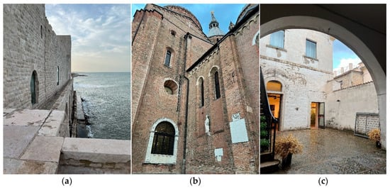
Figure 1.
Historic masonry structures in Italy: (a) Trani Castle (Trani, Puglia); (b) Basilica di Sant’Antonio da Padova (Padova, Veneto); and (c) Civic Museum “Carlo Gaetano Nicastro” (Bovino, Puglia).
To achieve an efficient representation of masonry composites while adequately accounting for the material’s inherent complexity, macro-scale modeling strategies are commonly employed in engineering practice.
In macro-scale approaches, masonry is modeled as an equivalent continuum through appropriate homogenization strategies. Several methodologies are available in the literature for reducing the composite to an equivalent Cauchy continuum in the linear-elastic field [30,31,32]. In the nonlinear field, these strategies, combined with advanced constitutive relationships, have been shown to be effective in those ranges of load cases under which texture-bond effects are not significantly engaged [25,26,33,34].
Anyway, there are several loading configurations in which texture-bond effects are not negligible, and for which the use of a Cosserat or micro-polar continuum has been proposed [35,36,37,38], including the presence of an internal length and the material micro-polarity through an enriched kinematics. These approaches may be applicable in the linear elastic regime; however, even in this case, their implementation is not straightforward, as it involves non-trivial difficulties in identifying the elastic parameters. When extending beyond the elastic range, these approaches become extremely difficult to manage and apply in practice.
In this framework, macro-scale discrete models based on the idea of reducing the composite to an assembly of rigid elements interconnected by elastic-plastic springs are particularly interesting [5,6,7,39,40,41], as they allow limiting the modeling and computational effort. These discrete models do not provide a detailed description at the micro-structural scale, as there is no coincidence between the real block arrangement and the rigid element mesh.
To better understand the potential of these approaches, it is worth referring to the Rigid Body-Spring Model (RBSM) scheme proposed by [5,6,7], which can be framed within the more generalized concept of heuristic molecule [4]. The RBSM-HM model involves the discretization of the homogenized masonry composite into rigid bodies called “heuristic atoms” interconnected by elastic-plastic springs to form “heuristic molecules”. This modeling strategy has been proven to be effective for modeling the characteristic masonry texture-bond behavior: interlocking, shear orthotropy, and Coulomb-like behavior at the macro-scale with a reduced number of degrees of freedom. Furthermore, the model has been demonstrated to be capable of reproducing the damage maps typically observed in post-seismic scenarios of buildings [41].
The early implementations of this model are limited in the possibility of controlling the Poisson effect. In this regard, the heuristic molecule approach “CSPF—Central, Shear, and Polar Forces” [4] proposed a solution based on the modeling of central forces acting on atoms. Based on this scheme, in the research work presented here, a specific, improved strategy was developed for modeling the in-plane shear behavior of masonry, considering the Coulomb-like behavior. It was implemented in a dedicated code and applied to an experimental reference case study to demonstrate the effectiveness of the approach.
3. Presentation of the Case Study: Shear Tests on Quarter-Scale Masonry Panels
In this study, a total of 37 experimental tests on 1:4 scale masonry panels were used as a reference to validate the proposed numerical approach. These tests were conducted at the Technical University of Catalonia (UPC), and their results were documented in the literature. The following section summarizes the key characteristics of the tests, while further details can be found in Ref. [8].
The test setup consisted of single-leaf running bond shear walls, constructed with solid clay bricks and cement mortar. The bricks measured 72.50 mm × 35.00 mm × 12.50 mm, while the mortar joints were 2.50 mm thick. Six different geometric layouts were developed and tested (Figure 2). The primary configuration was referred to as “Test A”, for which a total of 28 tests were performed. Layouts labeled as Tests B through E represent geometric variations in the main Test A, with only one test conducted for each typology (four in total). Finally, five tests were carried out on a wall with an opening, designated as Test F.

Figure 2.
The 1:4 scale shear walls tested in [8]: (a) primary test configuration of the wall; (b,c) walls with a variation in height; (d,e) walls with a variation in length; and (f) walls with opening.
A reinforced concrete beam was placed on top of each wall to apply the vertical pre-compression stress (σₙ) and the horizontal pushover stress (τₛ), as shown in Figure 3. The upper beam was generally allowed to rotate, except that in a part of the Test A cases, where rotation was constrained to assess the impact on the structural response. LVDTs were installed on each specimen to measure vertical and horizontal deformations.

Figure 3.
Experimental steps for shear tests: (a) application of the pre-compression load and (b) application of shear stress under constant pre-compression load.
Mechanical parameters of blocks and mortar were measured by specific laboratory tests on prisms—both in vertical and horizontal direction, and on the unit–mortar interface. The experimental results obtained for different panel typologies and varying magnitudes of pre-compression load are presented in Figure 4.
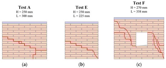
Figure 4.
Damage pattern obtained in the experimental tests: (a) Test A (primary wall configuration); (b) Test E (walls with a variation in length); and (c) Test F (walls with an opening).
The data obtained from the primary test series indicate that both the pre-compression load and the application of rotational restraint to the upper beam result in an increase in the shear strength of the panel. A reduction in panel height (Tests B and C) produces a slight increase in strength, whereas a decrease in panel width (Tests D and E) leads to a slight reduction. The presence of an opening in the panel (Test F) understandably causes a significant decrease in strength.
Across all test series, a low level of pre-compression was associated with a rocking collapse mechanism, characterized by failure of the horizontal joints and rigid rotation of the upper portion of the panel. Increasing the pre-compression load shifted the failure mode to shear, followed by diagonal cracking and ultimately crushing at the base.
4. Modeling the Masonry Panel Tests by Means of Heuristic Molecules
This section introduces the approach that is based on the discretization of panels as an assemblage of heuristic molecules. Section 4.1 presents the specific molecule developed. Section 4.2 describes their kinematics and the discretization designed for the case studies.
4.1. The “CSPF—Central, Shear, and Polar Forces” Heuristic Molecule
In this work, the philosophical “atomistic” approach based on the “CSPF—Central, Shear, and Polar Forces” molecule [4] was adopted for modeling the heterogeneous material. Each heuristic molecule (Figure 5) was made up of four rigid quadrilateral elements interconnected by elastic-plastic springs, with three types of connections: blue-axial, magenta-shear, and red-diagonal. The heuristic molecule is the “fundamental cell” that defines the minimum level of detail that can be described by the theoretical model.
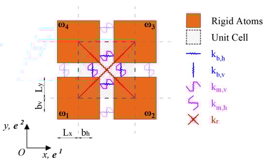
Figure 5.
The HM scheme: blue horizontal springs (parallel to mortar bed-joints); blue vertical springs; magenta horizontal springs; magenta vertical shear springs; and red central springs.
Rigid elements that are adjacent along their sides are connected to each other by the blue and magenta springs and are called “first–order” neighbors. Rigid elements that are adjacent only through a vertex are connected by the red diagonal springs and are called “second-order” neighbors.
The axial, non-central blue springs were arranged orthogonally to the sides and allowed the axial and the micro-polar inter-connection, being eccentric to the elements that were connected. They allowed equipping the model with an internal length, via the eccentricity parameters (horizontal springs) and (vertical springs).
The magenta springs are parallel to the sides and allow modeling shear actions between the elements. The distinction between horizontal and vertical magenta springs allows modeling texture-bond phenomena such as interlocking and shear orthotropy.
The red springs were arranged along the diagonals. They allowed modeling central actions between second-order neighbors and assured the Poisson effect under conditions of isotropy.
4.2. Kinematics of the Molecule and Discretization Adopted
Let us consider a global reference system (Figure 5) for the heuristic molecule. For modeling the unit cell’s kinematics, it is convenient to assemble the Lagrangian displacements and the work-conjugate external nodal forces and couples as follows:
Each bond-spring can be associated with a scalar strain measure , which is the first-order term of the change in the bond length divided by the original inter-atomic distance. The strain measures of the unit cell can be rearranged in the vector :
By rearranging the Lagrangian displacements into a vector and assembling a strain-displacement matrix for a given molecule, we obtain the following:
Given the elastic stiffnesses of all the inter-atomic bond-springs, these are assembled into a diagonal elasticity matrix :
The strain energy is directly related to the Lagrangian coordinates (Equation (6)), being the symmetric stiffness matrix of the numerical model and the diagonal matrix, which contains the volume associated to each bond-spring.
In this research, the previously described kinematics formulation of the HM scheme was implemented into a dedicated RBSM-HM code developed in MATLAB v. R2023b [42]. The approach was then applied and validated on the six case-study panels, discretized as illustrated in Figure 6 using a highly reduced number of heuristic atoms, ensuring a significant computational efficiency.
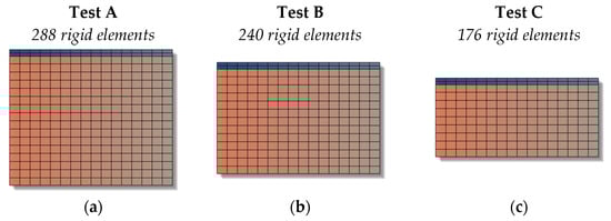
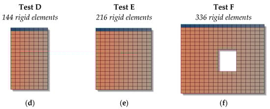
Figure 6.
Discretization in heuristic atoms adopted for (a) main wall; (b) and (c) walls with a variation in height; (d,e) walls with a variation in length; and (f) walls with opening.
In the numerical models, the lowest row of heuristic molecules was connected to a fictitious fixed base plane through axial and shear bond-springs. Where required, the rotation of the upper beam was restrained by applying an external moment. Pre-compression and shear loads were applied to the elements of the upper beam using a force-controlled procedure in two separate time steps, each lasting 3 s, with an increment of 0.001 s. To promote quasi-static system behavior and minimize convergence issues, the loads were applied following the time law illustrated in Figure 7.
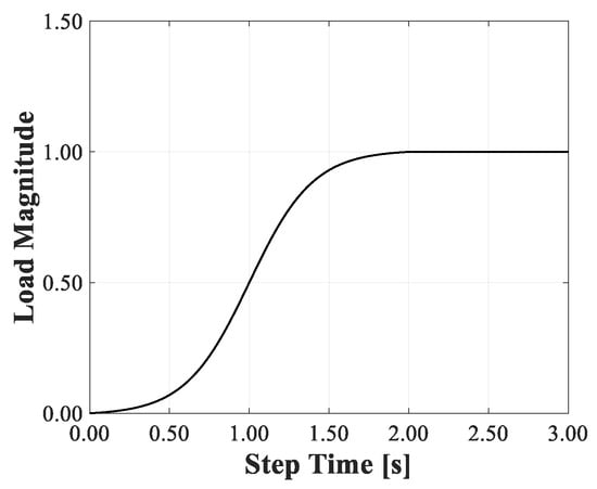
Figure 7.
The load-time function adopted in the numerical model.
5. Mechanical Modeling
Section 5.1 presents the definition of the elastic moduli of bond-springs, carried out by using an elastic energy equivalence criterion with a corresponding continuum. Section 5.2 identifies the collapse mechanisms at the meso-scale to show how the resistances assigned to bond-springs define the collapse mechanism at the macro scale. Finally, Section 5.3 presents the stress–strain laws assigned to bond-springs.
5.1. Definition of the Elastic Moduli of the Bond-Springs Through an Energy Equivalence-Based Criterion
According to the original framework proposed in [1], the elasticity of the CSPF-molecule can be formulated based on Cosserat solid in plane-stress conditions. In the case of isotropy, the stress–strain relation can be written as follows:
where is a parameter governing the skew-symmetric contribute to the shear elastic response and the length can be evaluated by comparing the elastic energy stored in the UC to the corresponding energy stored in a Cosserat solid continuum cell subjected to an in-plane curvature or . However, given the lack of experimental data for identifying the mechanical parameters of a Cosserat continuum equivalent to masonry, in this work, we adopted a reduced homogenization strategy based on a Cauchy continuum. When the principal orthotropy directions were aligned with the global reference axes , the elastic moduli of the bond-springs could be determined by assuming that the elastic strain energy stored in the fundamental cell was equal to the elastic strain energy stored in a “slightly” orthotropic Cauchy continuum having the same volume. The obtained values are summarized in Table 1.

Table 1.
Equivalent Cauchy continuum parameters and bond-springs’ elastic moduli.
5.2. Identification of the Collapse Mechanism at the Molecular-Scale
At the heuristic molecule scale, three shear collapse mechanisms can be identified: (i) sliding along the bed joint; (ii) rocking; and (iii) sliding with diagonal cracking. These mechanisms can be observed on panels at the macro-scale and can be applied at the meso-scale, i.e., at the heuristic molecule level (Figure 8), based on the relationships between external loads and bond-spring strengths.
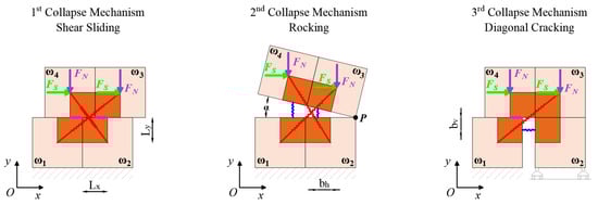
Figure 8.
Collapse mechanisms at the heuristic molecule’s Scale.
The shear strength of the panel subjected to a pre-compression stress and the pre-compression stress can be traced back to two forces and , acting on the portion of the rigid element falling within the fundamental unit cell, respectively, through Equations (8) and (9):
The occurrence of each mechanism depends on the strength characteristics assigned to the bond-springs:
- The strength of the magenta springs FM and the friction coefficient μ govern the shear sliding and diagonal cracking mechanisms.
- The compression strength of the red springs governs the shear sliding mechanism.
- The tensile strength of the red springs governs shear sliding, rocking and diagonal cracking.
- The tensile strength of the vertical blue governs the rocking mechanism.
- The tensile strength of the horizontal blue governs diagonal cracking.
The formulation of the equilibrium under collapse conditions for each mechanism allows understanding how the resistance assigned to the connecting springs promotes one mechanism over another.
By analyzing the first collapse mechanism and considering the increase in strength of due to the acting normal force, it is possible to write the equilibrium at the horizontal translation of the upper part of the molecule (Equation (10)):
From the second mechanism, by considering the rotation of the upper part around the pole P, it is possible to write the rotational equilibrium in collapse conditions, assuming that (Equation (11)):
Assuming a rigid rotation of the upper part with respect to the lower part, we found that and . Therefore, after posing and , we obtained Equation (12):
Regarding the diagonal cracking mechanism, writing the equilibrium at the horizontal translation of the unstable portion yields a relationship with the external force (Equation (13)):
Each collapse mechanism at the meso-scale is driven by the strength assigned to each spring bond. In the first case, the failure of the magenta springs causes sliding and a consequent loss of friction. In the second case, the failure of the vertical blue spring, due to an insufficient pre-compression, causes the rocking collapse mechanism. In the third case, the diagonal cracking mechanism is caused by the failure of the horizontal blue spring and the red spring.
5.3. Constitutive Laws Adopted to Model the Post-Elastic Response of the Bond-Springs
To account for mechanical nonlinearity, the RBSM-HM code implemented in MATLAB incorporates specific functions for modeling the nonlinear behavior of the central (red), shear (magenta), and polar (blue) connections in tests with monotonically increasing lateral loads (push-over).
The set of equations given in Equation (14) for the time increment is solved by using the Newmark Method and a full Newton–Raphson iteration scheme and adopting a convergence criterion (Equation (15)) based on the residual force determined at the iteration:
where is the mass matrix; is the damping matrix (determined assuming a critical Rayleigh damping); and are the velocity and acceleration vectors; is the vector of the “resisting forces”, and is the vector of the applied external forces, at the time :
The strength and friction coefficients of bond-springs were defined according to the strategies summarized in Table 2. The mechanical parameters provided by [8] (to which the reader is referred for further details) refer to peak values. Therefore, using these as a reference (as shown in Table 2), phenomenological constitutive laws were defined for modeling the entire deformation process of bond-springs.
Table 2.
Mechanical parameters of the model and strategy employed for their acquisition.
The stress–strain laws of the bond-springs were defined according to a phenomenological approach aimed at reproducing the behavior typically exhibited by masonry on a macro scale. Quasi-brittle collapse achieved with a marked nonlinear response, progressive degradation of stiffness and strength, significant inelastic deformations, and damage. Furthermore, the orthotropy of responses to axial and shear loads is considered by assigning different constitutive laws to the horizontal and vertical connections.
Figure 9a shows the skeleton curves of the axial and diagonal bond-springs, whereas Table 3 reports the corresponding parameter values. The points of the skeleton curve were labelled with the letters [S+, E+, E−, …]. The tensile strength assumed (point E+) is very low, corresponding to the value determined experimentally for the interfaces (see Table 2). The resulting tensile behavior is brittle, and low energy dissipation under cyclic loading is assumed. The compressive strength (point Y−) corresponds to that determined experimentally for the wall (Table 2). Under compression, once the peak strength is exceeded, energy dissipation occurs due to progressive damage caused by crushing.
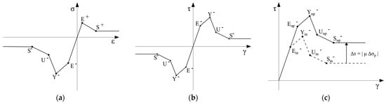
Figure 9.
Stress–strain laws adopted for bond-springs: (a) horizontal and vertical axial and diagonal bond-springs; (b) horizontal and vertical shear springs; and (c) the variation of the skeleton curve for modeling the Coulomb-like behavior, where points labeled as “initial” refer to the initial skeleton curve and points labeled as “updated” refer to the updated skeleton curve at the current time increment.
Table 3.
Parameters for axial and diagonal bond-springs’ constitutive law.
For shear bond-springs, the cyclic law, shown schematically in Figure 9b, is adopted, with the parameters defined in Table 4. These parameters refer to the initial skeleton curve defined without normal stress on the interface.
Table 4.
Parameters for shear bond-springs’ constitutive law.
The skeleton curves of the magenta bond-springs are initially symmetrical. As the load history proceeds, the skeleton curve of each spring is updated to consider the last stress value reached (points 1, 4, and 5 in Figure 9b). This degradation of strength is typically exhibited by masonry under cyclic loading conditions. For vertical bond-springs, the strength is higher than horizontal bonds, to model the interlocking effect. Both horizontal and vertical bonds, significant energy dissipation is assumed due to internal friction.
For Coulomb-like materials, shear strength depends on the normal compressive stress acting on the solid. To account for this effect, the skeleton curve of the spring is updated based on the value assumed by the normal stress on the interface. This stress component was determined using a specific function, and the points of the skeleton curve of the shear springs are translated by and . The friction coefficient is differentiated based on the orientation of the spring as follows: for horizontal springs (in accordance with Table 2) and for vertical springs. The result of this procedure is schematically represented in Figure 9c.
6. Results Obtained from Numerical Simulations
Section 6.1 presents the results obtained on the main series (Test A), also varying the constraint conditions of the top beam. Section 6.2 shows the results obtained by varying the dimensions of the panel (Tests B to E). Section 6.3 shows the results for the panel with the opening (Test F).
6.1. Primary Series Results (Test A)
The results obtained from the primary test series (A) are analyzed in terms of capacity curves, interaction domains, collapse mechanisms, and strain maps. Coherently with the Coulomb-like frictional behavior, the pre-stressing load does not affect the elastic response of the panel (Figure 10a). Below the threshold, , an increase in the pre-compression load corresponds to an increase in strength, while above this threshold, a decrease in strength is observed. When the pre-compression load increases, a reduction in ductility is always observed.
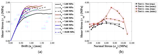
Figure 10.
Horizontal drift–shear stress relationships for Test A panels by varying the pre-compression load: (a) capacity curves in the presence of unconstrained upper beam and (b) interaction diagrams for the configurations with constrained and unconstrained upper beam.
The comparison between the numerical and experimental interaction domains (Figure 10b) shows that the numerical model adopted can qualitatively reproduce the bell-shaped curve observed experimentally. In the case of a panel with the beam free to rotate, a good correspondence between the numerical and experimental interaction domains was found. In the case of a panel with a restrained beam, for values of , there is good correspondence, while for , the model tends to underestimate the structural resistance.
To analyze the ability of the implemented numerical model in reproducing the experimental results, the percentage error obtained when evaluating the peak shear stress for each applied pre-compression load was computed and is shown in Figure 11. In most of the numerical tests, the error is generally within a range of +/−25%, which can be considered satisfactory.
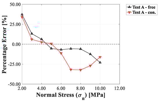
Figure 11.
Percentage error of the numerical simulations of Test A under shear.
The results in terms of deformed configuration of the panels, reported in Figure 12, show that the model effectively reproduces the collapse mechanism experimentally detected and the corresponding variations related to the pre-stressing load level, shifting from a rocking mechanism, for low values of , to a crushing mechanism, for high values of .
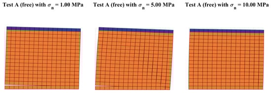
Figure 12.
Deformed shapes obtained from the numerical simulations of Test A panels by varying pre-compression load.
The strain maps (Figure 13) show that under a lower pre-compression load, axial, and diagonal springs undergo higher strains in the area where detachment occurs. The magnitude of these strains decreases as the pre-compression load increases. Under lower pre-compression load, horizontal shear springs suffer higher strain than vertical springs. However, a rise in the pre-compression load enhances the interlocking effect, thus inducing higher strains in the vertical spring bonds than in the horizontal bonds.
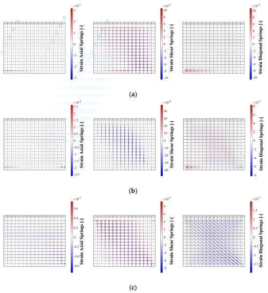
Figure 13.
Strain maps from the numerical simulations of Test A panels (unrestrained), panels with a pre-compression load of: (a) 1.00 MPa; (b) 5.00 MPa; and (c) 10.00 MPa.
To investigate how the different mechanical parameters of the model defined at the heuristic molecule scale affect the structural response of the panel, a sensitivity analysis was implemented. In this regard, a panel with geometrical characteristics of the Test A type was taken as a reference, with the upper beam free to rotate and a pre-compression load . The mechanical parameters of the reference model are shown in Table 5. The sensitivity analysis was implemented on (i) cohesion of horizontal shear springs; (ii) friction coefficient of horizontal shear springs; and (iii) tensile strength of axial blue springs (both horizontal and vertical) and diagonals. The variations in cohesion and tensile strength are matched by a scaling of the constitutive relationships, thus ensuring that the proportions between the elements of curves indicated in Table 3 and Table 4 are maintained.
Table 5.
Reference values adopted for the sensitivity analysis on model parameters.
Firstly, the tensile strength of the axial and diagonal bonds, as well as the friction coefficient of the horizontal magenta, was left unchanged. The following values were adopted for cohesion: , (reference model) e . The results of this initial analysis are shown in Figure 14a.
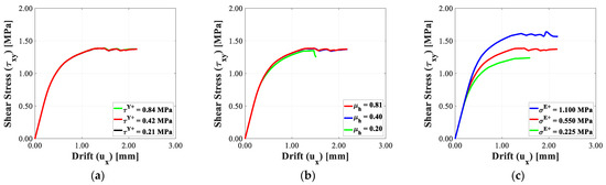
Figure 14.
Numerical results obtained from the sensitivity analysis by varying: (a) horizontal shear springs’ cohesion; (b) horizontal shear springs’ friction coefficient; and (c) axial and diagonal springs’ tensile strength. The red curves always correspond to the reference model.
Subsequently, maintaining the reference values for tensile strength of both axial and diagonal bonds as well as the cohesion of horizontal shear springs, the values , , and were adopted for the friction coefficient of the latter. The results are shown in Figure 14b.
Finally, the cohesion and friction coefficient of the horizontal shear bond-springs are left unchanged, and the values , , are adopted for the tensile strength of the axial and diagonal bonds. The results of this final analysis are shown in Figure 14c, where the cohesion and the friction coefficient have a negligible influence on the capacity curves obtained, whereas the tensile strength does. This is related to the collapse mechanism, which was observed (Figure 12) and essentially involved the rocking collapse. Consequently, the model proved to be capable of approximating not only the collapse mechanism observed at the structural scale, but also the role of each bond-spring in driving a specific collapse mechanism.
6.2. Walls with Varied Dimensions (Tests B to E)
The results obtained from the test series with varied dimensions were qualitatively analyzed in terms of capacity curves and numerical interaction domains. For the collapse mechanisms and strain maps, no significant variations were observed compared to the results obtained for Test A.
The numerical results obtained for Tests B and C showed that a decrease in the panel height led to an increase in shear strength. The capacity curves determined for Tests B and C (Figure 15a) followed the trends already outlined for Test A. The trends observed for Test A were also observed for the interaction domains (Figure 15b).
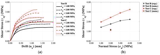
Figure 15.
Horizontal drift–shear stress relationships for Test B and C panels by varying the pre-compression load: (a) capacity curves and (b) interaction diagrams.
Both experimentally and numerically, a decrease in the panel width (Tests D and E) produces a decrease in the strength. The capacity curves (Figure 16a) show the same trends outlined for Test A, while the interaction domains (Figure 16b), with their typical geometry, are very close to the experimental value, .
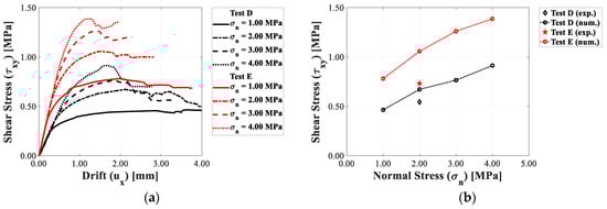
Figure 16.
Horizontal drift–shear stress relationships for Test D and E panels varying the pre-compression load: (a) capacity curves and (b) interaction diagrams.
6.3. Wall with Opening (Test F)
The capacity curves obtained for panels with opening (Figure 17a) show that once the threshold of is exceeded, increase in pre-compression load is not correlated with further significant increases in strength. The numerical interaction diagram (Figure 17b) is very close to the experimental one. In fact, the percentage error obtained is always comprised within the range +/− 8%.
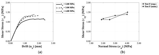
Figure 17.
Horizontal drift–shear stress relationships for Test F panels varying the pre-compression load: (a) capacity curves; (b) interaction diagrams.
The model can reproduce the collapse mechanism obtained experimentally. In fact, Figure 18 shows a rocking mechanism characterized by failure of the mortar bed joints at the bottom left, sliding along the joints at the top right and failure of the blocks on the right side of the panel. The strain maps show patterns that are entirely comparable to the damage patterns detected experimentally.
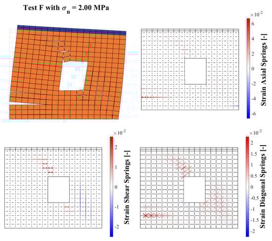
Figure 18.
Deformed shape and strain maps obtained for the Test F panel with a pre-compression load of 2.00 MPa.
7. Conclusions and Future Developments
The paper presents an enhanced numerical strategy for modeling the in-plane shear response of masonry panels subjected to different pre-stressing vertical loads. The model is based on the RBSM-HM approach, which discretizes the heterogeneous solid according to a topology in which the elementary cells consist of quadrilateral rigid atoms interacting through elastic–plastic springs. The main improvement over earlier RBSM formulations lies in the definition and implementation of additional diagonal bond-springs that interact with the original bond-springs specifically assigned to angular deformation. To model texture-bond effects (interlocking, orthotropy of axial, and shear response) and Coulomb-like behavior using a limited number of degrees of freedom, a specific RBSM-HM code was implemented in MATLAB.
The research work was specifically focused on the model’s capacity to reproduce the shear response and damage mechanisms of masonry panels characterized by a regular and periodic bond texture. To this end, a reference is made to an experimental campaign [8] comprising 37 tests performed on six small-scale masonry panels subjected to varying levels of pre-compression and different boundary conditions. The results indicate that the model successfully simulates the experimental response. In particular, the capacity curves exhibit consistent trends, showing increased strength and reduced ductility with higher pre-compression levels, while the numerical interaction domains qualitatively match experimental ones. The computed strain maps and deformed configurations are also in good agreement with the observed behavior. At low prestressing levels, the numerical model reproduces a rocking collapse mechanism involving failure of the horizontal interfaces and rotation of the upper portion of the panel. As the prestressing load increases, the model captures a transition first to a shear-type collapse and subsequently to a failure mode characterized by diagonal cracking and crushing at the base.
The application and validation presented in this work are subject to certain limitations, primarily due to the specific test setups and the corresponding availability of datasets and results. In particular, the validation was performed for a single type of masonry—namely, a periodic arrangement composed of clay bricks with thin mortar joints—and relied on a single experimental benchmark dataset, which included only monotonic tests for this masonry configuration. Consequently, at this stage, applications and validation for different masonry typologies and under cyclic or dynamic loading conditions have not been possible. These aspects will be addressed in future developments. Nevertheless, these limitations do not compromise the general capability of the proposed approach to account for texture-bond effects across different masonry textures, nor its potential to model shear orthotropy in masonry materials, thanks to its sound theoretical foundation.
In conclusion, the proposed model demonstrated strong potential to describe the shear damage response of a complex heterogeneous material, due to its straightforward definition of mechanical parameters, the quality and reliability of the results obtained, and its high computational efficiency. Future developments will focus on extending the approach to simulation of dynamic response and nonlinear seismic analyses of large-scale masonry structures, to fully validate and showcase the capabilities of the proposed modeling strategy.
Author Contributions
Conceptualization, S.C. and G.U.; methodology, S.C., G.U. and L.S.R.; software, S.C. and L.S.R.; validation, S.C., G.U. and L.S.R.; formal analysis, S.C. and L.S.R.; investigation, L.S.R.; resources, G.U.; data curation, S.C. and L.S.R.; writing—original draft preparation, S.C. and L.S.R.; writing—review and editing, S.C., G.U. and L.S.R.; visualization, S.C. and L.S.R.; supervision, S.C. and G.U. All authors have read and agreed to the published version of the manuscript.
Funding
This research received no external funding.
Data Availability Statement
The original contributions presented in this study are included in the article material. Further inquiries can be directed to the corresponding author(s).
Conflicts of Interest
The authors declare that they have no conflicts of interest.
References
- Celano, T.; Argiento, L.U.; Ceroni, F.; Casapulla, C. Literature Review of the In-Plane Behavior of Masonry Walls: Theoretical vs. Experimental Results. Materials 2021, 14, 3063. [Google Scholar] [CrossRef]
- Vasconcelos, G.; Lourenço, P.B. In-plane experimental behavior of stone masonry walls under cyclic loading. J. Struct. Eng. 2009, 135, 1269–1277. [Google Scholar] [CrossRef]
- Lourenço, P.B.; Mendes, N.; Ramos, L.F.; Oliveira, D.V. Analysis of masonry structures without box behavior. Int. J. Archit. Herit. 2011, 5, 369–382. [Google Scholar] [CrossRef]
- Casolo, S. A linear-elastic heuristic-molecular modelling for plane isotropic micropolar and auxetic materials. Int. J. Solids Struct. 2021, 224, 111042. [Google Scholar] [CrossRef]
- Casolo, S. Modelling in-plane micro-structure of masonry walls by rigid elements. Int. J. Solids Struct. 2004, 41, 3625–3641. [Google Scholar] [CrossRef]
- Casolo, S. Macroscopic modelling of structured materials: Relationship between orthotropic Cosserat continuum and rigid elements. Int. J. Solids Struct. 2006, 43, 475–496. [Google Scholar] [CrossRef]
- Casolo, S. Macroscale modelling of microstructure damage evolution by a rigid body and spring model. J. Mech. Mater. Struct. 2009, 4, 551–570. [Google Scholar] [CrossRef]
- Drougkas, A.; Roca, P.; Molins, C. Experimental analysis and detailed micro-modeling of masonry walls subjected to in-plane shear. Eng. Fail. Anal. 2019, 95, 82–95. [Google Scholar] [CrossRef]
- Gambarotta, L.; Lagomarsino, S. Damage models for the seismic response of brick masonry shear walls. Part I: The mortar joint model and its applications. Earthq. Eng. Struct. Dyn. 1997, 26, 423–439. [Google Scholar] [CrossRef]
- Gambarotta, L.; Lagomarsino, S. Damage models for the seismic response of brick masonry shear walls. Part II: The continuum model and its applications. Earthq. Eng. Struct. Dyn. 1997, 26, 441–462. [Google Scholar] [CrossRef]
- Lucchesi, M.; Padovani, C.; Pasquinelli, G.; Zani, N. Masonry Constructions: Mechanical Models and Numerical Applications; Springer: Berlin/Heidelberg, Germany, 2008. [Google Scholar] [CrossRef]
- Addessi, D.; Marfia, S.; Sacco, E.; Toti, J. Modeling approaches for masonry structures. Open Civil. Eng. J. 2014, 8, 288–300. [Google Scholar] [CrossRef]
- Silva, L.C.; Mendes, N.; Lourenço, P.B.; Ingham, J. Seismic structural assessment of the Christchurch catholic Basilica, New Zealand. Structures 2018, 15, 115–130. [Google Scholar] [CrossRef]
- Lourenço, P.B.; Silva, L.C. Computational applications in masonry structures: From the meso-scale to the super-large/super-complex. Int. J. Multiscale Comput. Eng. 2020, 18, 889. [Google Scholar] [CrossRef]
- Lagomarsino, S.; Degli Abbati, S.; Ottonelli, D.; Cattari, S. Integration of Modelling Approaches for the Seismic Assessment of Complex URM Buildings: The Podestà Palace in Mantua, Italy. Buildings 2021, 11, 269. [Google Scholar] [CrossRef]
- Pietruszczak, S.; Przecherski, P. Macro-Mesoscale Submodeling Approach for Analysis of Large Masonry Structures. Buildings 2025, 15, 2382. [Google Scholar] [CrossRef]
- Grillanda, N.; Mallardo, V. Compatible strain-based upper bound limit analysis model for masonry walls under in-plane loading. Comput. Struct. 2025, 313, 107743. [Google Scholar] [CrossRef]
- Pantò, B.; Cannizzaro, F.; Caddemi, S.; Caliò, I. 3D macro-element modelling approach for seismic assessment of historical masonry churches. Adv. Eng. Softw. 2016, 97, 40–59. [Google Scholar] [CrossRef]
- Azevedo, J.; Sincraian, G.; Lemos, J.V. Seismic Behavior of Blocky Masonry Structures. Earthq. Spectra 2000, 16, 337–365. [Google Scholar] [CrossRef]
- Cundall, P.A.; Strack, O.D.L. A discrete numerical model for granular assemblies. Geotechnique 1979, 29, 47–65. [Google Scholar] [CrossRef]
- Kawai, T. New discrete models and their application to seismic response analysis of structures. Nucl. Eng. Des. 1978, 48, 207–229. [Google Scholar] [CrossRef]
- Lemos, J.V. Discrete element modeling of masonry structures. Int. J. Archit. Herit. 2007, 1, 190–213. [Google Scholar] [CrossRef]
- Lubliner, J.; Oliver, J.; Oller, S.; Oñate, E. A Plastic-Damage Model for Concrete. Int. J. Solids Struct. 1989, 25, 299–326. [Google Scholar] [CrossRef]
- Lee, J.; Fenves, G.L. Plastic-Damage Model for Cyclic Loading of Concrete Structures. J. Eng. Mech. 1998, 124, 892–900. [Google Scholar] [CrossRef]
- Rainone, L.S.; Tateo, V.; Casolo, S.; Uva, G. About the Use of Concrete Damage Plasticity for Modeling Masonry Post-Elastic Behavior. Buildings 2023, 13, 1915. [Google Scholar] [CrossRef]
- Rainone, L.S.; Tateo, V.; Casolo, S.; Uva, G. Advanced Non-Linear 3D FEM Modeling of Masonry Structures for the Preservation of Cultural Heritage. In Proceedings of the CEUR WORKSHOP PROCEEDINGS, Bari, Italy, 1 September 2024; Volume 3838, No. Code 204216. pp. 1–12. Available online: https://ceur-ws.org/Vol-3838/paper5.pdf (accessed on 2 October 2025).
- Lazaridis, P.C.; Thomoglou, A.K. Rapid shear capacity prediction of TRM-strengthened unreinforced masonry walls through interpretable machine learning deployed in a web app. J. Build. Eng. 2024, 98, 110912. [Google Scholar] [CrossRef]
- Ravichandran, N.; Bidorn, B.; Mercan, O.; Paneerselvam, B. Data-Driven Machine-Learning-Based Seismic Response Prediction and Damage Classification for an Unreinforced Masonry Building. Appl. Sci. 2025, 15, 1686. [Google Scholar] [CrossRef]
- Estêvão, J.M.C. Effectiveness of Generative AI for Post-Earthquake Damage Assessment. Buildings 2024, 14, 3255. [Google Scholar] [CrossRef]
- Anthoine, A. Derivation of the In-Plane Elastic Characteristics of Masonry through Homogenization Theory. Int. J. Solids Struct. 1995, 32, 137–163. [Google Scholar] [CrossRef]
- Pande, G.N.; Liang, J.X.; Middleton, J. Equivalent elastic moduli for brick masonry. Comput. Geotech. 1989, 8, 243–265. [Google Scholar] [CrossRef]
- Michel, J.C.; Moulinec, H.; Suquet, P. Effective properties of composite materials with periodic microstructure: A computational approach. Comput. Methods Appl. Mech. Eng. 1999, 172, 109–143. [Google Scholar] [CrossRef]
- Zucchini, A.; Lourenço, P.B. A micro-mechanical model for homogenization of masonry. Int. J. Solids Struct. 2002, 39, 3233–3255. [Google Scholar] [CrossRef]
- Gatta, C.; Addessi, D.; Vestroni, F. Static and dynamic nonlinear response of masonry walls. Int. J. Solids Struct. 2018, 155, 291–303. [Google Scholar] [CrossRef]
- Bouyge, F.; Jasiuk, I.; Ostoja-Starzewski, M. A micromechanically based couple-stress model of an elastic two-phase composite. Int. J. Solids Struct. 2001, 38, 1721–1735. [Google Scholar] [CrossRef]
- Muhlhaus, H.-B. Application of Cosserat theory in numerical solution of limit load problems. Ing.-Arch. 1989, 59, 124–137. [Google Scholar] [CrossRef]
- Sulem, J.; Muhlhaus, H.-B. A continuum model for periodic two-dimensional block structures. Mech. Cohesive-Frict. Mater. 1997, 2, 31–46. [Google Scholar] [CrossRef]
- van der Sluis, O.; Vosbeek, P.H.J.; Schreurs, P.J.G.; Meijer, H.E.H. Homogenization of heterogeneous polymers. Int. J. Solids Struct. 1999, 36, 3193–3214. [Google Scholar] [CrossRef]
- Pantò, B.; Cannizzaro, F.; Caliò, I.; Lourenço, P.B. Numerical and experimental validation of a 3D macro-model for the in-plane and out-of-plane behavior of unreinforced masonry walls. Int. J. Archit. Herit. 2017, 11, 946–964. [Google Scholar]
- Bertolesi, E.; Milani, G.; Casolo, S. Homogenization towards a mechanistic Rigid Body and Spring Model (HRBSM) for the non-linear dynamic analysis of 3D masonry structures. Meccanica 2018, 53, 1819–1855. [Google Scholar] [CrossRef]
- Casolo, S. Macroscale modelling of the orthotropic shear damage in the dynamics of masonry towers by RBSM. Eng. Fail. Anal. 2021, 130, 105744. [Google Scholar] [CrossRef]
- The MathWorks Inc. MATLAB Version: 23.2.0.2515942 (R2023b) Update 7; The MathWorks Inc.: Natick, MA, USA, 2024. Available online: https://www.mathworks.com (accessed on 28 March 2025).
Disclaimer/Publisher’s Note: The statements, opinions and data contained in all publications are solely those of the individual author(s) and contributor(s) and not of MDPI and/or the editor(s). MDPI and/or the editor(s) disclaim responsibility for any injury to people or property resulting from any ideas, methods, instructions or products referred to in the content. |
© 2025 by the authors. Licensee MDPI, Basel, Switzerland. This article is an open access article distributed under the terms and conditions of the Creative Commons Attribution (CC BY) license.