Abstract
Afghanistan experiences frequent damaging earthquakes, and the widespread use of unreinforced adobe and Pakhsa construction leads to high casualty rates and severe housing losses. Traditional earthen buildings exhibit low tensile capacity, rapid stiffness degradation, and brittle failure, often collapsing at drift levels below 0.5–0.6% or at modest ground motions. Reinforcement techniques evaluated in international experimental studies—such as timber confinement, flexible steel wire mesh, geogrids, and high-quality plastic fencing—have demonstrated measurable improvements, including 30–200% increases in lateral strength, three- to seven-fold increases in ductility, and out-of-plane capacity enhancements of more than two-fold when properly anchored. This study synthesises research findings and global earthen building codes and guidelines to develop a practical, context-appropriate benchmark house model for Afghanistan. The proposed model integrates representative wall geometries, concentrated flat-roof loading, and realistic construction capabilities observed across the country. Three reinforcement alternatives are presented, each designed to be low-cost, compatible with locally available materials, and constructible without specialised equipment. By linking quantitative performance evidence with context-specific construction constraints, the study provides a technically grounded and implementable pathway for improving the seismic safety of rural earthen dwellings in Afghanistan. The proposed benchmark model offers a robust foundation for future national guidelines and for the design and retrofitting of safer, more resilient housing.
1. Introduction
The seismic history of Afghanistan has been documented since the 8th century A.D, although the history of destructive earthquakes in the region exists as far as more than four thousand years ago [1,2]. Afghanistan is located on the southern fringe of the Eurasian plate and its seismicity is mostly due to the northward movements of the Indian plate past eastern and Arabian plate past western Afghanistan with respect to the Eurasian plate. Crustal earthquakes in the country are concentrated at plate boundaries to the east and west of Afghanistan where both the Indian plate and Arabian plate subduct under the Eurasian plate. Mantle earthquakes are mostly concentrated beneath the Hindu Kush and Pamirs. In addition to regional seismicity, the seismic hazard, especially in northeastern Afghanistan, is also influenced by nearby potentially active seismic faults, most of which lack sufficient details for seismic hazard assessments [2,3,4]. These local and regional faults have contributed to triggering strong earthquakes in the past and warn of strong earthquakes in the future.
Civil engineering infrastructure, primarily buildings and houses, often sustains catastrophic damage during earthquakes. In Afghanistan, these devastating consequences stem from the collapse of earthen buildings, mostly houses, which are single- or two-storey buildings made of mud, sun-dried bricks, and stone masonry, with no reinforcement to withstand earthquakes. Only about 25% of the Afghan population lives in cities, of which a small portion lives in engineered buildings, mostly reinforced concrete. The majority of city populations live in non-engineered houses with no means of earthquake resistance. More than 85% of the Afghan population lives in walled houses made of bricks, stone masonry, and mud, which increases the vulnerability of the population and the severity of destruction during major earthquakes.
Over a period of 25 years, from 1998 to 2023, there have been more than 15 significant earthquakes, ranging from Richter magnitudes 5.3 to 7.5, which resulted in over 12,500 deaths, 30,000 injuries, and the destruction of 60,000 homes (Figure 1), leaving 190,000 people homeless (Table 1). It has been reported that almost all these casualties and all this destruction were sustained by the populations living in non-engineered earthen houses [5,6,7]. The aftermath of a strong earthquake that results in thousands of deaths significantly impacts the psychological well-being of survivors, particularly those in mud housing. Grief, anxiety, and feelings of helplessness can overwhelm individuals as they confront loss and destruction. The fear of future earthquakes exacerbates feelings of vulnerability, leading to chronic anxiety and hyper-vigilance. Economic hardship further complicates recovery, as many families lack the resources to rebuild, intensifying despair and hopelessness.
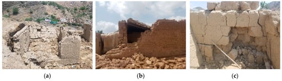
Figure 1.
Earthquake destruction of mud houses (Paktika, Afghanistan, June 2022): (a) out-of-plane collapse of Pakhsa wall, (b) roof collapse, and (c) wall collapse due to large diagonal crack and horizontal cracks at joints between two Pakhsa (monolithic mud wall layer).

Table 1.
Large earthquakes that caused considerable casualties (1998–2023).
Although the damage to earthen buildings is a source of financial loss and causalities during earthquakes, earth/mud is still one of the oldest and most widely used building materials globally, particularly in developing countries such as Afghanistan. It has been reported that 30% to 60% of the global population lives or works in earthen buildings, with a notably higher percentage of the population in developing countries residing in earthen dwellings [20,21,22,23]. In Afghanistan, according to Arya et al. (a) [24], almost 95% of houses were made of earth prior to 2003.
According to Thompson et al. [25], living in earthen houses is not only unavoidable but also desirable, as this building typology embodies cultural values and offers environmental advantages, even though earthquakes are an unavoidable natural phenomenon. Therefore, to mitigate the devastating effects of earthquakes on mud houses, it is essential to construct them with earthquake-resistant designs. The responsibility for ensuring earthquake-resistant construction of earthen buildings primarily falls on the government and technical institutions, which must provide guidelines, raise public awareness, and enforce these standards. However, in Afghanistan, institutions currently lack the necessary capacity and infrastructure for research, development, and enforcement of codes, standards, or guidelines related to earthquake-resistant design and construction of earthen buildings. Consequently, it is crucial to assess how existing reinforcement techniques from other countries can be adapted for use in Afghanistan.
This paper addresses this question by reviewing the literature and relevant earthen building codes and guidelines on seismic strengthening for new and existing earthen buildings. While adobe brick construction is common globally, monolithic mud wall/Pakhsa construction is one of the most common earthen constructions in Afghanistan. Like Arya et al. (a) [24], Foley [26] also reported that 94% of dwellings are made of Pakhsa or mud bricks. Pakhsa construction shares similarities with rammed earth construction, allowing for a review of reinforcement techniques for both adobe and rammed earth to propose strengthening methods for adobe and Pakhsa buildings in Afghanistan. Notably, no research on Afghanistan’s Pakhsa construction is found in the literature.
2. Earthen Construction: Sustainability and Environmental Impact
As noted by Jiménez [27], earthen buildings are sustainable, have low environmental impact, and provide indoor comfort. In Afghanistan, these structures are also vital due to economic, technical, and social factors. While global warming and climate change are critical challenges, the construction sector, as an important contributor, accounts for about one-third of global carbon emissions and nearly 40% of energy use [20,23]. Raw earth is a sustainable material that can be easily sourced locally, minimising embodied energy [21,22].
LaFrance [28] highlighted that CO2 emissions continue to rise, with the IEA projecting a potential doubling by 2050. Thus, reducing energy consumption and carbon emissions in buildings is essential for climate policy, as discussed by Cabeza et al. [29]. While earlier frameworks emphasised operational carbon emissions from lighting and cooling, studies show that embodied carbon from construction materials largely drives overall emission, as demonstrated by [30,31]. According to Kofoworola and Gheewala [32], embodied carbon can be up to 42% of total life cycle emissions.
Cabeza et al. [33] reported that traditional materials like rammed earth, stone, and timber generate the least emissions. According to the authors, earth materials typically range from 0.0 to 0.025 kg CO2/kg, while reinforced concrete ranges from 0.19 to 0.24 kg CO2/kg, and steel averages 2.53 to 2.71 kg CO2/kg. Mud-brick houses have significantly lower carbon intensity compared to reinforced or structural steel. According to Aste et al. [34], thermal efficiency of building envelopes is crucial for reducing overall energy consumption, since the building sector consumes about 32% of global energy, with 37% of that used for heating and cooling [35,36]. Insulating these envelopes can significantly lower energy costs, and unfired clay bricks outperform fired ones in terms of thermal performance as discussed by [37,38]. Bruno et al. [39] as well Indekeu et al. [40] reported that earth walls also provide substantial hygro-thermal inertia, acting as moisture and heat buffers, thereby stabilising indoor humidity and temperature. Additionally, according to Datta and Mustafa [41], raw earth is biodegradable and can be recycled, reducing hazardous waste.
3. Characteristics of Earthen Houses in Afghanistan
Most rural houses in Afghanistan are surrounded by 3 to 5 m high compound walls known as “Qala” (Fort/Castle) covering up to 10,000 square metres for security and privacy and, in addition to the house itself, have spaces for parking, storage, animal shelter, and small gardens. Rooms are constructed along one side inside the Qala to optimise sunlight, with verandas for outdoor gatherings (Figure 2). The architectural design of Afghan mud and brick houses has evolved. Traditionally, these homes had fewer rooms, lower ceilings, narrower doorways, and limited windows, with walls made of mud and straw plaster. They generally lacked electrical and plumbing systems. Contemporary mud houses feature more rooms, taller ceilings, larger windows, and may include amenities, depending on family economics and urban proximity. New constructions may involve engineers or architects, but many remote areas rely on local masons without formal training. Most Afghan earthen buildings can be divided into unfired (adobe) brick houses and layered poured mud (Pakhsa) houses, with Pakhsa houses being more prevalent and larger.
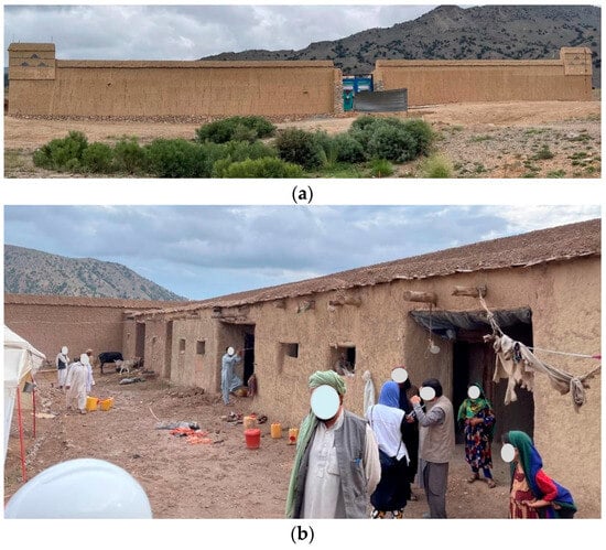
Figure 2.
(a) Monolithic mud (Pakhsa) compound wall, (b) rooms are constructed along one side inside the Qala to optimise sunlight. Reprint with permission [42]; copyright 2022, Miyamoto International, Inc.
3.1. Raw/Unfired Clay Brick Houses: Construction Techniques and Materials
Adobe brick houses are less common than poured layered mud or Pakhsa houses, primarily serving small single-family homes or expedited construction. These single- or rarely double-storey walled buildings are often built on dry-stone masonry wall foundations. The foundations are placed about half a metre to a metre below ground level and the same height above ground level. The foundation width is generally the same as the width of the wall, 350 to 500 mm. After raising the masonry foundation to the desired height above ground level, a layer of mud mortar is applied, forming bedding for the first layer of adobe bricks. Mortar layers range from 1 to 3 cm thick, with wall thicknesses between 35 and 50 cm. Bricks are typically produced on-site using simple tools, often without knowledge of soil properties. As mentioned by Dhandhukia et al. [43], optimal compressive strength is achieved with a soil composition of approximately 55% sand and 45% silt and clay, with a plastic limit of 2–6%. Wood lintels are installed at the desired opening height, often about 500 mm below the level of ceiling, covered by one or two additional brick layers. A final layer of mud mortar is applied before placing the roof beam on top (Figure 3). Roof beams, known as Dastak, are round wood logs with a diameter of at least 150 mm, spaced about 0.6 m apart. Smaller wood members (50 mm round or split, called Walch) or wood planks span the main beams. Reed or similar plants cover the Walch, topped with a 60 to 100 mm layer of foot-compacted clay (Ghora-Gel) and a 3 to 5 cm layer of fine-grained dry clay (Khoshki), which is then waterproofed with polythene sheeting and protected by straw-mud plaster (Kah-Gel). Roofs are flat with a slight slope for drainage, but they are not attached to the walls, leading to common roof failure mechanisms (Figure 1).
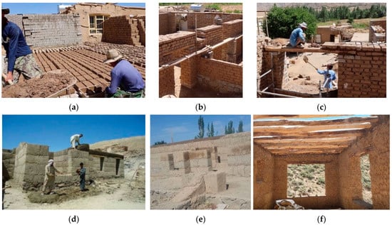
Figure 3.
Construction of earthen houses. (a–c) Adobe brick earthen house construction. Reprinted with permission [44]; copyright 2020, Bamyan TV. (d,e) Pakhsa wall construction. Reprinted with permission [45]; copyright 2022, IMT—Mines Alès. (f) A Pakhsa wall room with wood beams under construction. Reprinted with permission [46]; copyright 2020, ROSTA Film.
3.2. Monolithic Mud/Pakhsa Houses: Construction Techniques and Materials
Mud/Pakhsa houses are primarily single-storey, though occasionally double-storey, earth-walled constructions made from kneaded mud in the form of thick poured layers formed by hand. They feature dry-stone masonry foundations set 0.5 to 1.0 m below ground, generally extending to the same height above ground. Once the masonry foundation is complete, the first layer of the mud wall, known as Pakhsa, is constructed, typically measuring 0.4 to 0.6 m in height.
The construction of each Pakhsa layer involves several steps:
- Soil Procurement: Sufficient cohesive soil is gathered along the length of the wall.
- Wet Mixing: The dry clay is wetted by ponding with water. No fibres or other additives are used in Pakhsa wall construction.
- Kneading: The wet earth is kneaded/puddled and pressed, often by animals walking over the mixture. This process, which may include turning the mixture with a shovel 2–3 times, eliminates air pockets and enhances the consistency of the mud, aligning clay particles to improve plasticity and moldability.
- Application: After a while (less than 24 h), the prepared mud is transferred to the mason using a handheld shovel. Each shovelful is piled and compressed by hand or foot to avoid cavities, achieving a depth of about 500 mm. Thus, a three-metre-tall wall will require six 0.5 m high Pakhsa layers.
- Levelling: The mason levels the wet Pakhsa to prepare it for the next layer using a flat-headed wooden mallet.
- Shaping: Once the Pakhsa has dried sufficiently to support the weight of a person but remains soft enough for carving, the mason shapes both faces using a plumb bob and handheld trowel, ensuring the wall is plumb and maintains the desired thickness. The wall width typically ranges from 500 mm to 700 mm.
After allowing the Pakhsa about five days to attain the necessary strength, this process is repeated for each layer until the desired wall height is achieved. The final Pakhsa is placed atop the wall, on round roof beams. The roofing of mud houses employs techniques and materials like those used in brick houses. According to Alejandro and Dermot [47], this technique resembles cob, traditionally used in the British Isles and Brittany, but without the use of natural fibres.
4. Study Methodology
This paper conducts a comprehensive review of the relevant literature, earthquake-resistant codes, standards, and normative documents related to various techniques and provisions for reinforcing earthen buildings to enhance their seismic resistance. The aim is to evaluate these reviewed techniques and guidelines to develop a unified set of specifications and reinforcement methods in the form of an earthquake-resistant model earthen house, serving as a guide for upgrading adobe and Pakhsa wall houses in rural Afghanistan.
Relevant data from various sources are summarised in tabulated form (Table A1, Table A2, Table A3, Table A4, Table A5, Table A6, Table A7, Table A8, Table A9, Table A10 and Table A11) for analysis and comparison. The review of research papers will provide insights into the different types of tested specimens (Table A1 and Table A2), types and techniques of potential reinforcement (Table A3 and Table A4), assessing their effectiveness (Table A4 and Table A5) and applicability to earthen construction in Afghanistan. Factors such as cost, material availability, sustainability, local architecture, construction typology, and the skills required for implementation will be considered. Additionally, the review of standards, codes, and normative guidelines will summarise key earthquake-resistant design and construction features from various sources into a tabular format (Table A7 and Table A8). After identifying key provisions from each publication, a comprehensive set of unified specifications will be proposed for the construction of both adobe brick (Table A10) and Pakhsa wall earthen buildings (Table A11), considering the unique characteristics of these earthen structures in the country.
As a conclusion, an earthquake-resistant earthen model house will be developed, incorporating specifications from various relevant standards and different reinforcement options and application techniques, which will serve as a guide model for adapting to earthquake-resistant earthen houses.
5. Identification of Relevant Documents for Review
In Afghanistan, the two primary types of earthen buildings are walled un-fired clay brick structures and mud wall/Pakhsa buildings, as previously defined. While numerous laboratory studies (Table 2) have focused on earthquake reinforcement and strengthening adobe brick buildings (some of which have been incorporated into building codes for the design and construction of earthen structures), there has been no laboratory research on earthquake-resistant design and construction for Pakhsa house buildings.
Table 2.
List of journal papers reviewed.
Rammed earth walls share several characteristics with Pakhsa construction, including wall thickness, comparable heights of rammed earth blocks and Pakhsa, and similar unit weights. Given these similarities, the authors propose that reinforcement techniques used in rammed earth construction could also be adapted for mud/Pakhsa wall systems. Consequently, this review examines sources related to earthquake-resistant rammed earth construction to propose earthquake-resistant design and construction guidelines for mud/Pakhsa buildings. The reviewed publications include only those journal papers (JPs), standards (Ss), building codes (BCs), and normative documents (NDs) published by technical organisations that contains seismic design and construction provisions. Table 2 lists the reviewed journal papers, and Table 3 presents the list of reviewed building codes, standards, and technical guidelines relevant to earthquake-resistant design and construction of adobe brick and rammed earth construction.
Table 3.
List of reviewed building codes (BCs), standards (Ss), and normative documents (NDs).
Some references, such as [49,51,54], are not included in the comparative analysis due to limited experimental details, similarity to other studies, or unavailability of the full text, ensuring that the tables are based on sources with sufficiently detailed and verifiable information.
6. Review of Journal Papers, Standards, Building Codes, and Normative Guidelines
This chapter offers a technical review of experimental research and normative documents on the seismic resistance and retrofitting of adobe and rammed earth buildings, presented in two parts: Section 6.1, covering scholarly experimental evidence, and Section 6.2, examining relevant standards and codes. Key numerical results, specimen geometries, loading protocols, reinforcement details, and material properties are cross-referenced with the summary tables in Appendix A (Table A1, Table A2, Table A3, Table A4, Table A5, Table A6, Table A7, Table A8, Table A9, Table A10 and Table A11). Table A1 and Table A2 outlines the tested samples, Table A3 and Table A4 summarise reinforcement types and arrangements, and Table A5 and Table A6 compile the main qualitative and quantitative findings. The features of earthquake-resistant design from the reviewed standards listed in Table 3 are consolidated in Table A7 and Table A8 to support the unified specifications proposed for the model earthquake-resistant earthen house. Each subsection concludes with a brief note on evidence quality.
6.1. Detailed Technical Review of Journal Publications
6.1.1. Studied Samples—Size and Configuration
The experimental corpus encompasses a range of models, from small wall panels to compound configurations, including C-, I-, L-, T-, and U-shaped assemblies, as well as 1:4 to full-scale single-room house models, selected to replicate specific boundary conditions and capture diverse in-plane and out-of-plane failure mechanisms (Table A1 and Table A2). Planar adobe walls have been investigated in [57,58,59,61,62,63,65], whereas rammed earth wall panels were studied in [62,64,67]. Compound adobe and rammed earth wall assemblies (C-, I-, L-, T-, and U-shaped) were examined in [52,55,60,62,63,65,66,69,73,74]. These corner geometries sometimes including openings (e.g., door/window spaces) were used to simulate realistic building layouts and induce out-of-plane actions. The corner geometry provided stiffness restraint in one direction while allowing out-of-plane displacements in the orthogonal wall, effectively capturing torsional effects, wall-wall interaction, and complex load paths typical of actual earthen houses. A relatively smaller portion of laboratory programmes focused on single-span box specimens with relatively thin walls (≤300 mm) [48,49,50,51,53,54,56,68,70,71,72], providing consistent data for characterising shear and diagonal cracking. Specimen dimensions varied widely, with lengths of 0.8–5.8 m, heights of 0.8–3.45 m, and wall thicknesses of 50–600 mm, reflecting both laboratory constraints and attempts to approximate traditional field construction. Fewer studies [62,63,64,65,69,73,74] investigated thicker walls (>400 mm), typical of Afghan adobe and Pakhsa houses, where mass, slenderness, and wall-roof interactions may significantly influence structural behaviour.
6.1.2. Loading Protocols and Measured Response Parameters
The reviewed studies employed a range of loading protocols to characterise the seismic behaviour of adobe and rammed earth walls (Table A1). Two primary approaches dominated: quasi-static cyclic lateral loading and dynamic shaking-table testing. Small- and medium-scale wall panels were most frequently subjected to quasi-static cyclic protocols [55,58,59,60,61,62,63,67,69,73], enabling detailed measurement of initial stiffness, peak shear capacity, displacement or drift limits, ductility indices, and hysteretic energy dissipation (Table A5). These controlled tests provided the most complete quantitative datasets and form the basis for the percentage improvements summarised in Table A5. However, because panel tests omit system-level effects such as diaphragm interaction, corner confinement, gravity mass distribution, and three-dimensional load transfer, their quantitative results cannot be directly generalised to full-scale buildings.
Dynamic and shaking-table tests were used less frequently but provided essential information on the global seismic response of full-scale adobe houses, U- and L-shaped assemblies, and thick rammed earth walls [50,51,52,53,56,62,63,65,68,70,71,72,74]. These experiments produced fewer direct numerical measurements but captured system-level behaviours including cracking progression, rocking response, residual drift, out-of-plane stability, and collapse prevention (Table A5 and Table A6). The geometric scale and configuration of these specimens, often incorporating multi-wall assemblies and wall thicknesses of 0.40–0.60 m, limited the acquisition of complete force-displacement curves, resulting in primarily qualitative descriptions of global performance.
Additional loading arrangements included diagonal compression, tilting-platform tests, monotonic lateral loading, and out-of-plane pull-down tests applied to wall panels, U-shaped assemblies, and full-house specimens [48,57,64,66]. These protocols were used to isolate specific mechanisms such as shear capacity, overturning behaviour, and out-of-plane bending resistance. Across the literature, the choice of loading protocol reflected the targeted failure mode and specimen geometry: cyclic testing provided quantitative comparison of reinforcement strategies, while dynamic and tilt-based methods clarified system-level behaviour and collapse mechanisms. Together, these methodologies define the quantitative and qualitative parameters used for the comparative synthesis in Section 6.1.6.
6.1.3. Boundary Conditions in Experimental Studies
Foundation/Base Restraint
Most investigations mounted specimens on reinforced concrete bases providing fixed or near-fixed support. Studies evaluating strengthening systems incorporating vertical or timber elements—such as bamboo or timber posts, PVC/steel bars, external mesh strips, or tie-rod systems—compared anchored and unanchored configurations. Anchored walls consistently exhibited reduced rocking and sliding, greater lateral stability, and higher energy dissipation. Anchorage of timber frames, vertical tendons, or mesh connectors improved lateral stiffness and limited residual drift, particularly under strong shaking. Tests on adobe and RE walls confirm that mechanical foundation anchorage substantially improves the seismic effectiveness of reinforcement [48,50,55,65,68,70]. These experimental findings were subsequently translated into post-earthquake reconstruction practice in Peru, where reinforced adobe houses incorporated plain concrete foundations, collar beams acting as lintels, improved wall-to-wall connectors, and shear keys at collar-beam intersections to limit sliding and separation under seismic loading [83]. Further refinements proposed the use of vertical dowels connecting foundations to mesh reinforcement and collar beams, shown to reduce rocking response and mitigate shear-friction failures at wall-beam interfaces [84].
Axial (Vertical) Loading
Axial loading was applied to simulate roof mass or gravity stresses (Table A1). Full-scale house models generally relied on their own roof weight [50,51,52,53,56,67,70,71,72], whereas panel tests applied controlled vertical precompression. Adobe walls were commonly loaded between 0.1 and 0.32 MPa [62,63,64,65,69,73], while thicker RE walls were loaded at lower stresses (0.008–0.08 MPa). Some studies varied axial load to quantify its influence: increased vertical stress delayed cracking and enhanced shear resistance within a limited range [62]. Axial compression was introduced through rigid steel or concrete loading beams or collar beams to ensure uniform distribution. Axial load magnitude and uniformity were therefore major determinants of shear capacity and drift performance.
Roof/Diaphragm/Top Boundary Conditions
Shaking-table studies used timber roofs, collar beams, or lightweight roof prototypes [48,53,56,68,70,71,72], which acted as diaphragms contributing to load distribution and top confinement. Some cyclic tests on multi-leaf or geometrically complex walls used stiff crown beams to provide continuity and to apply combined vertical and lateral loading [55,69,73]. In contrast, tests isolating shear or bending mechanisms—such as diagonal compression panels [57] or out-of-plane pull-down tests [66]—often left the top edge unrestrained. Thus, top boundary restraint varied according to the targeted behavioural mode: diaphragms were included when assessing system-level response, whereas free-top or beam-supported conditions were selected for fundamental shear or flexural characterisation.
6.1.4. Reinforcement Materials, Application Techniques, and Anchorage Conditions
Across the reviewed experimental programmes, the seismic effectiveness of adobe and rammed earth reinforcements depends not only on the choice of material but also—often more critically—on how these materials are applied, anchored, and integrated with the substrate (Table A3 and Table A4). Reinforcement performance is governed by three interdependent factors: (i) the mechanical characteristics of the reinforcement material; (ii) the continuity and distribution of the applied system; and (iii) the interface and anchorage conditions that ensure load transfer between the reinforcement and earthen wall. The following synthesis integrates material types, application strategies, and anchorage practices reported in the literature.
Metallic Reinforcement Systems
Metallic solutions—including steel wire meshes, welded wire meshes, steel rebars, steel wire ropes, and A36 steel plates—represent the most widely tested reinforcement category. Wire meshes are typically surface-mounted on both faces and attached with nails and screws; they are tied together with through-wall connectors (steel bolts, rods, solid timber, or tie wires) and then covered with a 1:4 cement-sand mortar to prevent delamination and ensure confinement [52,53,54,55,62,66]. In some studies, rebars were placed vertically and horizontally on both faces and tied across the wall thickness, enhancing global confinement and improving shear transfer [61]. A36 steel plates, mounted externally and clamped through the wall with steel tie rods or bolts, formed stiff confinement jackets that significantly increased lateral load capacity but occasionally introduced brittle post-peak behaviour if not balanced with ductile detailing [63].
Metallic systems generally require robust anchorage at the foundation and/or roof beams to be fully effective. Studies consistently show that the presence of anchored mesh edges or through-rods reduces rocking, mitigates separation at wall-foundation interfaces, and improves cyclic stability. The literature highlights that insufficient anchorage—not material weakness—is the most common cause of premature failure in metallic retrofits.
Polymeric, Geosynthetic, and Textile Reinforcement Systems
A broad array of polymeric solutions has been evaluated, including geogrids, geonets, polyester/PP meshes, nylon ropes, soft plastic fencing, tarpaulin strips, and proprietary geo-meshes (e.g., Tensar products). These systems are generally lighter and more flexible than metallic meshes, permitting easier on-site handling and improved compatibility with irregular earthen surfaces. These systems are mostly applied on both external surfaces of walls, partially or fully covering the walls. Nylon rope mesh systems have also been validated through full-scale shaking-table tests, in which cracked single-storey adobe house models were retrofitted using tensioned rope meshes connected across wall thickness and re-tested under strong ground motions, demonstrating effective collapse prevention and preservation of structural integrity [71,85]. Based on this experimental evidence, an engineering design approach for rope mesh reinforcement was developed and later incorporated into the Peruvian earthen construction code, Norma E.080 [75].
- Geogrids and geo-mesh are typically surface-mounted on both faces of walls. They are sometimes attached to the wall by plastic plugs and mostly tied together using through-wall connectors (nylon/plastic tie wires, steel bolts, and rods) [55,56,58,60,62,68].
- Polypropylene/polyethylene geonets are commonly fixed to the walls using U-shaped steel staples [59].
- Nylon meshes/nylon rope meshes and plastic meshes are attached to the wall using plastic plugs and nylon strings or tie rods to maintain cross-wall continuity [60,71,72,73,74].
- Tarpaulin strips are adhered using specialised adhesives as mechanical fastening is not feasible [64].
Polymeric systems generally exhibit favourable ductile behaviour when plastered, particularly when mesh continuity, overlap, and anchorage at boundary elements are ensured. Several studies reported improved hysteretic stability and enhanced displacement capacity with geogrid systems tied to collar beams or ring beams [55,62,68]. Conversely, insufficient fastening or inadequate bonds can lead to premature peel-off, limiting their contribution to shear resistance. Experimental studies further demonstrate that the effectiveness of polymer and PP-band mesh reinforcement depends strongly on the tightness of mesh installation and the presence of protective plaster layers, which improve load transfer, reduce gap formation, and protect polymers from ultraviolet exposure and temperature-related degradation [86].
Natural Fibre and Traditional Reinforcement Systems
Traditional plant-based materials—bamboo, cane, palm meshes, reed mats, and palm ropes—appear prominently in earlier studies and remain attractive due to local availability and sustainability. Vertical bamboo poles (often 1.5× wall thickness) combined with split canes embedded every fourth adobe course represent a common historical approach [48,49,50,55]. These elements are typically tied or interwoven through the wall thickness, enhancing out-of-plane stability and providing restraining action during cyclic lateral loading.
Palm mesh and reed reinforcements, when tied with palm ropes and embedded in clay-straw plaster, have shown meaningful improvements in energy dissipation and fragmentation control [58]. However, their effectiveness is highly sensitive to anchorage quality, mortar infill, and mesh density; poorly tied systems tend to slip or rupture under cyclic loading.
Timber-Based Reinforcement and Confining Systems
Timber elements—including vertical posts, horizontal belts, timber frames, and surface-mounted planks—provide a versatile means of improving in-plane and out-of-plane resistance. Timber planks and frames are usually anchored through the wall using 8 mm steel bolts or solid timber connectors, while in some studies they are integrated with post-tensioning elements for enhanced confinement [65,66,69]. Continuous timber frames have proven particularly effective in delaying out-of-plane collapse and reducing residual drift, especially when tied to foundation sills or ring beams.
6.1.5. Influence of Key Variables
- 1.
- Material Properties and Additives
Earthen materials are intrinsically brittle with low tensile strength and limited ductility [50,52,55,58]. Mechanical performance improves with the inclusion of fibres, straw, or industrial meshes, which delay crack propagation and enhance post-peak stability [57,58,65]. Synthetic solutions, including polymer mesh, geosynthetics, polypropylene (PP) band meshes, and textile-reinforced mortars (TRMs), provide enhanced energy dissipation, drift capacity, and collapse prevention after cracking, despite their limited contribution to initial stiffness due to low elastic rigidity relative to masonry [55,56,70,73,74,87]. Mortar type, soil composition, and ageing of materials also significantly affect stiffness, strength, and damping properties [57,67].
- 2.
- Wall Geometry, Openings, and Boundary Conditions
Wall height, thickness, aspect ratio, and openings critically influence in-plane and out-of-plane responses [62,65,69,72]. Taller walls and those with large openings are prone to diagonal cracking, shear failure, and overturning. Adequate anchorage at foundations and crown beams is essential, particularly for multi-storey adobe constructions [50,52,65,69,72]. Corners and intersections are high-stress regions; poor reinforcement in these zones reduces the effectiveness of retrofit measures [52,62,72].
- 3.
- Reinforcement Strategies and Retrofitting
Experimental evidence demonstrates multiple effective reinforcement strategies:
- Cane mesh and crowning tie beams: Interior cane mesh with tie beams improves wall integrity, limits separation, and delays collapse [50,52,55]. Horizontal confinement is crucial; its absence causes premature collapse [50,52,55].
- Wood boards with steel rod ties: Provide moderate delay of collapse by distributing tensile stresses [52].
- Rope and nylon mesh: Installed in channels or tied through walls, they reduce drift, confine cracks, and prevent overturning, effective even in two-storey buildings [52,72].
- Wire mesh with mortar: External welded wire mesh covered with cement mortar provides tensile continuity, increases lateral strength, and improves out-of-plane stability [52,55,56,62,70].
- Polymer and geosynthetic meshes: Low-cost alternatives offering high ductility and post-peak stability, capable of preventing collapse under strong seismic motions [55,56].
- Textile-reinforced mortar (TRM): Enhances ductility (peak drift increase up to 700%) and energy dissipation and avoids collapse in rammed earth walls, although original stiffness is not fully restored [73,74].
- Geo-mesh in earth-based mortar: Redistributes stresses under out-of-plane cyclic loading, improves displacement capacity, and delays structural instability [74].
The success of these strategies depends on continuous wall coverage, secure anchorage, and proper detailing at corners and intersections [52,59,62,67].
- 4.
- Cyclic Loading, Dynamic Behaviour, and Energy Dissipation
Shaking-table and cyclic lateral loading tests reveal the following:
- Unreinforced walls exhibit brittle failure, rapid stiffness degradation, limited drift, and minimal energy dissipation [50,52,56,65,72].
- Reinforced walls maintain structural integrity, demonstrate stable hysteresis, allow higher drift, and dissipate more energy [55,57,62,67,69,72,73,74].
- Rope meshes and TRM provide improved recentring and allow repeated seismic events without collapse [72,73].
- Dynamic properties, including period elongation and damping, are improved in reinforced walls, although initial stiffness may remain below that of an undamaged unreinforced wall [73,74].
- 5.
- Axial Load and Confinement Effects
Applied axial compression increases lateral load capacity in unreinforced walls, while reinforced walls show limited sensitivity to vertical loads due to confinement provided by meshes, ropes, or TRM systems [62,65]. Proper confinement at edges and intersections is critical to limit out-of-plane drift and residual displacements [52,65,69,72].
- 6.
- Failure Modes and Collapse Prevention
Common failure modes include diagonal cracking, corner crushing, rocking, plaster detachment, and overturning [50,51,52,58,59,65,72]. Reinforced walls redistribute stresses; reduce crack localization; increase lateral strength and peak-sustained deformation and ductility; and delay/prevent failure, enhancing occupant safety [52,55,56,67,70,71,72,73,74]. Low-cost, locally available reinforcements (rope, polymer mesh, and TRM) are effective in preventing catastrophic collapse even under severe shaking [50,55,56,72].
- 7.
- Practical Considerations
- Cost and accessibility: Reinforcements are typically low-cost and locally available [50,51,52,55,57,58,70,71,72,73,74].
- Installation and detailing: Correct anchorage, wall coverage, and corner treatment are vital [51,52,59,62,67].
- Sustainability: Natural fibre and rope reinforcements are environmentally friendly and compatible with heritage structures [58,72].
- Multi-storey and heritage buildings: Reinforcement must balance structural performance with architectural preservation; excessive permanent drift may not be acceptable for heritage walls [62,71,72].
6.1.6. Synthesis of Experimental Results
Experimental evidence clearly establishes that unreinforced adobe and RE walls perform poorly under seismic loads due to low strength, stiffness degradation, and brittle mechanisms. Strengthening methods—from meshes and geogrids to TRM, timber, steel plates, NSM bars, and rope nets—substantially improve seismic performance. Strength typically increases by 30–200%, ductility by factors of 3–7, and drift capacity by 2–2.5%. Energy dissipation grows dramatically, and collapse—especially out-of-plane—is consistently prevented (Table A5 and Table A6).
Even where stiffness is not restored, strengthened walls exhibit controlled, ductile deformation and maintain integrity under repeated or strong shaking. Many techniques are low-cost, culturally compatible, and suitable for high-risk, low-resource settings. Together, these findings show that practical, scalable seismic retrofitting of earthen buildings is achievable, effective, and essential for risk reduction and heritage preservation. Field evidence following major earthquakes corroborates these experimental observations, as reinforced adobe houses constructed using mesh-based and collar-beam systems demonstrated excellent seismic performance during the 2007 Mw 8.0 Pisco earthquake, while neighbouring unreinforced dwellings suffered severe damage or collapse [88].
Global Strength and Stiffness Trends
Unreinforced specimens consistently exhibited rapid damage progression, including diagonal shear cracking and shear failure [52,58,63,64], brittle out-of-plane cracking and degradation [62,63], limited deformation capacity due to poor crack accommodation [60,63], pinched hysteresis from repeated crack opening/closure [63], corner separation in multi-wall configurations [60,68], weak mortar-block bond failure [60], and abrupt post-peak collapse [48,49,50,51,52,53,54,55,66]. Reinforcement markedly improved performance. Vertical bamboo canes anchored to foundations and tied with horizontal split canes increased wall strength [48], and externally nailed steel wire mesh with cement mortar prevented collapse in full-scale adobe modules [52,53,54], but several studies report that its post-elastic response may become unstable, with stiffness loss and brittle failure modes developing under strong shaking if ductile detailing is insufficient [55,89]. NSM steel bars increased lateral strength by up to 181% [61], flexible welded wire mesh tripled ductility, ultimate displacement, and shear capacity at a low axial load [62], and polyester strips [67], palm/reed meshes [58], plastic/geosynthetic meshes [55,59], and nylon rope nets [72] enhanced load capacity, energy dissipation, and stability. Timber planks provided 70% higher lateral capacity, 2.5-fold displacement capacity, and a 10-fold energy dissipation increase [69], while steel plates raised in-plane and out-of-plane strength by 30% and 60% [63]. Timber confinement more than doubled out-of-plane static capacity, and foundation anchorage significantly reduced rocking and residual drift [65].
Stiffness trends are more nuanced. Some systems—steel plates [63], cement-mortared welded wire mesh [62], and timber confinement [69]—increase initial stiffness. Others, especially TRM [73] and polymer/nylon mesh systems [55,59,70,71], aim not to stiffen but to stabilise, enabling ductile deformation without restoring original elastic stiffness. Thus, while strength gains are consistent across techniques, stiffness outcomes depend strongly on material compatibility and load transfer details.
Deformability, Drift Capacity, and Ductility
Unreinforced walls typically fail at global drifts below 0.5–0.6% for in-plane loading and exhibit similarly limited out-of-plane drift tolerance [63,69]. Dynamic tests show collapse of unretrofitted adobe between PGA 0.14 and 0.39 g [63,65,69].
Strengthening significantly enhances deformation capacity. Plaster meshes and additives [57] and palm/reed systems [58] consistently improve ductility; diagonal near-surface mounted (NSM) reeds increase displacement capacity by up to 60% [58]. Polyester strips [67] allow strengthened walls to withstand four additional displacement cycles, increasing cumulative deformation capacity by a factor of 4–5. TRM [73] yields dramatic gains: drift at peak load increases by 235–700% compared to the original wall. Nylon rope reinforcement [72] multiplies displacement capacity by 3–5 for two-storey buildings under strong shaking. Timber grids with post-tensioning [69] allow walls to reach drifts of 2.5%—five times the original capacity.
Energy Dissipation and Cyclic Stability
Unreinforced adobe and RE exhibit low cumulative energy dissipation and strong hysteretic pinching due to diagonal cracking, sliding, and early stiffness loss [59,61,63]. Strengthened systems substantially increase energy dissipation. Palm and reed retrofits [58] produce fuller hysteresis loops; although palm meshes show more pinching, they achieve higher cumulative energy dissipation than NSM reeds. Polyester strips [67] decrease per-cycle dissipation but increase cumulative dissipation up to four-fold due to extended cycling before failure. Meshes and geonets in [55,56,59,62] improve cyclic stability by delaying crack opening and preserving integrity at large drifts. TRM [73] dissipates ~60% of input energy with stable damping and no collapse. Rope mesh retrofits [72] reduce residual drifts and maintain stable hysteresis, while timber and steel systems [63,65,69] enable extensive cycling without instability.
Out-of-Plane Performance and Collapse Prevention
Unreinforced earthen walls are particularly vulnerable to out-of-plane demands. Studies [63,65,69,74] show brittle rocking-type failures at low accelerations, with rapid loss of stability and little warning. In [65], collapse occurred between 0.91 and 0.95 g in quasi-static tests but at much smaller shaking intensities (0.39 g) on the table.
Strengthening yields transformative improvements. Timber grids [65,69] increase out-of-plane capacity by factors of 2.3–2.4 and prevent overturning even at PGA = 0.72 g. Steel plates [63] enable walls to resist accelerations up to 0.52 g without collapse and maintain stability at roof accelerations >1.64 g. Geogrids, welded wire meshes, and polymer meshes [55,56,62] significantly delay overturning and maintain integrity even when large residual drifts develop. TRM and geo-mesh-based strengthening [73,74] greatly improve out-of-plane deformation limits, preventing catastrophic buckling by redistributing stresses.
Influence of Axial Load, Boundary Conditions, and Damage State
Axial load effects are mixed. For unreinforced walls, increased axial compression generally raises peak strength but reduces displacement capacity and accelerates degradation [61,62]. Strengthened walls show weaker or inconsistent dependence on axial load: meshes in [62] and NSM systems in [61] show little additional benefit at higher vertical stress, as confinement provided by reinforcement dominates over axial compression.
Boundary conditions strongly influence wall performance. Adobe walls with end confinement fail later and at higher accelerations than isolated walls [65], while strengthened walls remain stable even with reduced confinement. Foundation anchorage of timber elements [69] notably decreases residual drift during strong shaking.
Initial damage state also matters. TRM applied to a previously damaged RE wall [73] improved ductility and prevented collapse but could not restore original stiffness. Similar observations apply to mesh systems in [56,74]: reinforcement enhances safety but does not erase the structural effects of pre-existing cracks.
Failure Modes and Mechanism Shifts
Unreinforced walls fail through brittle diagonal shear cracking, sliding, or rocking; out-of-plane failure is sudden and catastrophic. Studies [57,58,59,61,63,71] describe localization of cracks and rapid loss of load capacity.
Strengthening shifts failure to more distributed, ductile mechanisms. Mesh-based systems (polymer, polyester, palm, straw, and geosynthetic) distribute cracking and maintain coherence even after significant wall damage [55,57,58,59,67]. TRM [73] and geo-mesh systems [74] transform localised bending cracks into distributed damage patterns, delaying instability. Nylon rope nets [72] and timber grids [65,69] confine wall segments, preventing separation and changing failure into controlled rocking. Steel plates [63] change the governing mechanism to bearing-driven ductile behaviour, avoiding diagonal cracks.
Practicality, Sustainability, and Applicability
Many studies emphasise low-cost, locally available, and easy-to-apply systems. Polymer meshes [55,56], PP-band meshes [70], nylon rope nets [71,72], and plastic meshes [56] are affordable, easy to install, and compatible with traditional construction. While welded wire mesh systems are technically effective, their relatively high material and labour costs limit large-scale adoption in low-income rural contexts, particularly when compared with polymer, rope, or textile-based alternatives [55,90]. Natural fibres—straw, palm, and reeds [57,58]—offer sustainable, culturally compatible solutions. Timber systems [65,69] provide robust improvement but require careful detailing and may intrude on historic interiors. Steel plates [63] are effective and minimally invasive but require corrosion protection. Bamboo canes greatly improve the strength of adobe models, but their use is limited to internal installation during new construction and is impractical for retrofitting or for regions where bamboo is not readily available. TRM systems [73,74] balance compatibility and reversibility, making them promising for heritage preservation.
6.2. Review of Earthquake-Resistant Provisions of Earthen Construction in Seismic Codes, Standards, and Normative Documents
Building codes set minimum safety and performance requirements and have historically evolved following major earthquakes (e.g., Japan after the 1923 Great Kantō earthquake and California after the 1933 Long Beach earthquake, Olshansky [91]). Afghanistan frequently experiences severe seismic damage, particularly to earthen dwellings, and its current guidelines require revision to reflect local materials, vernacular construction practices, and recent advancements. Persistent challenges include limited technical capacity, scarce data, and weak enforcement, as noted by Mashal et al. [92]. In this section, the features of earthquake-resistant design from the reviewed standards listed in Table 3 are consolidated in Table A7 and Table A8 to support the unified specifications proposed for the model earthquake-resistant earthen house.
6.2.1. Codes, Standards, and Normative Documents Reviewed
Peru—Norma E.080:2017
Norma E.080 (2017) [75], issued by the Ministry of Housing, Construction and Sanitation of Peru, is the national regulation governing design, construction, and repair of earthen buildings, including adobe and rammed earth. It provides a modern, comprehensive framework with annexes covering soil testing and detailed reinforcement systems, including plant-based fibres, geogrids, and synthetic rope meshes.
Nepal—NBC 204:2015
NBC 204 (2015) [76], published by the Government of Nepal’s Department of Urban Development and Building Construction, establishes national requirements for earthquake-resistant earthen construction. It is complemented by NBC 203 [93] for low-strength masonry and the Nepal Reconstruction Authority (NRA) Design Catalogues [94], forming a unified set of practical, field-level guidelines.
New Zealand—NZS 4297, NZS 4298, NZS 4299
Developed by Standards New Zealand, these documents constitute the country’s principal earth-building regulatory suite. NZS 4297 [77] provides engineering design procedures; NZS 4298 [78] establishes materials, workmanship, and testing requirements; and NZS 4299 [79] gives acceptable solutions for limited-design and non-engineered earthen buildings. The suite has been updated to incorporate findings from post-earthquake investigations and full-scale testing of adobe walls.
India—IS 13827:1993 (Reaffirmed 2003)
IS 13827:1993 [80], published by the Bureau of Indian Standards (BIS), provides guidelines for improving the seismic safety of non-stabilised traditional earthen dwellings (adobe, rammed earth, and similar vernacular systems). It is intended for widespread rural application and focuses on simple construction and strengthening techniques.
IAEE Guidelines—Guidelines for Earthquake Resistant Non-Engineered Construction
Originally issued by the International Association for Earthquake Engineering (IAEE) in 1980 as “Basic Concepts of Seismic Codes, Vol. 1, Part II” [95], this foundational document outlines global principles for seismic provisions in non-engineered construction. A later revised version (Arya et al. [81], adapted from the original [96], which itself is a revision of [95]) consolidates these principles and extends guidance to fired brick, concrete block, confined masonry, timber, stone, and earthen buildings. It remains an important reference where national codes are absent, outdated, or incomplete.
Construction Manual for Earthquake-Resistant Houses Built of Earth (Minke)
This manual by Minke [82], published through GATE-BASIN (Building Advisory Service and Information Network), originated from international research supported by the German Research Foundation (DFG), GTZ GmbH, and the University of Kassel. Rooted in field studies in Latin America and prototype testing, it provides practical construction and reinforcement guidance for adobe, rammed earth, textile earth-filled, and wattle-and-daub systems.
Afghanistan—Guidelines for Earthquake-Resistant Design, Construction, and Retrofitting of Buildings (2003)
These were developed by the United Nations Centre for Regional Development (UNCRD) and the Ministry of Urban Development and Housing (MUDH) of Afghanistan and authored by Prof. Anand S. Arya [24]. These 2003 guidelines consist of five parts, with Part E dedicated to earthen houses, covering site selection, material suitability, and construction and reinforcement details similar in scope to IS 13827 [80].
6.2.2. Technical Review of Codes, Standards, and Normative Documents
Site and General Requirements
National and regional standards for earthquake-resistant earthen construction display notable convergence despite differences in terminology, material culture, and seismic context (Table A7 and Table A8). While Norma E.080 [75] defines four seismic zones, NZS 4297/4298/4299 [77,78,79], IS 13827:1993 [80], Arya et al. (b) [81], and Arya et al. (a) [24] each employ three-tier classifications, whereas NBC 204 [76] and Minke [82] provide non-zonal, nationally applicable provisions. All documents prohibit construction on unstable soils—with a range including loose sands, expansive clays, fills, liquefaction-prone sediments, riverbanks, steep slopes, or areas subject to flooding, erosion, or landslides—and emphasise site drainage, roof overhangs, and protective plinths as primary moisture-defence measures. Environmental protection provisions are consistently embedded in these documents: Norma E.080 [75] mandates plinths, coatings, plasters, and adequate roof eaves; NBC 204 [76] requires damp-proof courses, roof projections, plastering, and drainage; NZS 4299 [79] prescribes rain deflection, drainage, and damp-proof courses; IS 13827:1993 [80] requires plinths, mud plasters, roof overhangs, and site drainage; Arya et al. (b) [81] specifies two-layer plaster, mud stucco, and bitumen application; Minke [82] discusses earthen wall protection conceptually; and Arya et al. (a) [24] mandates plinths, mud plasters, roof overhangs, and drainage. Plan configuration requirements further reinforce structural regularity: Norma E.080 [75] allows rectangular and symmetric plans and even curved walls; NBC 204 [76] requires symmetrical or regular rectangular plans with a maximum 3:1 length-to-breadth ratio; NZS 4299 [79] restricts layouts to rectangular forms; IS 13827:1993 [80] requires rectangular or symmetric plans; Arya et al. (b) [81] prescribes square rooms and symmetric plans; Minke [82] promotes compact square forms with ribbed rammed earth walls; and Arya et al. (a) [24] specifies rectangular and symmetrical plans. Provisions for construction on slopes are limited but explicit where present: NZS 4299 [79] permits building on slopes ≤20°, while NBC 204 [76] and Arya et al. (a) [24] provide slope-related guidance without quantified thresholds. Norma E.080 [75], IS 13827:1993 [80], Arya et al. (b) [81], and Minke [82] do not include equivalent slope criteria. Height limitations are broadly aligned, with the majority of documents restricting earthen buildings to a single storey, permitting attics or a second storey only in lower seismic zones or under controlled geometric conditions.
Footings and Plinths
All standards require continuous, load-bearing footings on firm natural ground. Norma E.080 [75], IS 13827:1993 [80], Arya et al. (b) [81], and Arya et al. (a) [24] allow stone or brick masonry and cyclopean or lean concrete footings; NBC 204 [76] specifies stone or burnt-brick masonry; NZS 4299 [79] mandates reinforced-concrete strip footings with a minimum soil bearing capacity of ≥300 kPa; and Minke [82] provides qualitative guidance rather than prescriptive footing configurations. Minimum footing widths range from the wall thickness to approximately 700 mm, with embedment depths from 400 to 750 mm. Plinths serve both structural and moisture-protection functions. All standards require a minimum plinth height of ≥300 mm above the finished ground level, although NZS 4299 [79] permits 200–375 mm. Waterproofing is addressed through polythene sheets, damp-proof courses, or waterproof muds, with erosion-resistant external facings mandated by IS 13827:1993 [80], Arya et al. (b) [81], and Arya et al. (a) [24].
Materials and Wall Design
Strength criteria vary considerably. Norma E.080 [75] uniquely defines allowable prism compressive, tensile, and shear strengths, while NBC 204 [76], IS 13827:1993 [80], Arya et al. (b) [81], and Arya et al. (a) [24] specify a 1.2 MPa adobe unit strength. NZS 4298 [78] requires ≥0.5 MPa for unstabilised units and introduces standardised test procedures, whereas Minke [82] provides qualitative recommendations without quantification. Minimum wall thicknesses range from 280 to 450 mm, with ≥380 mm being the most common (Table A7 and Table A8). All codes prescribe clay-sand mixtures; some include straw reinforcement (Norma E.080 [75], IS 13827:1993 [80], and Arya et al. (a) [24]), and all require the pre-wetting of adobes or bricks. Slenderness limits are consistent at L/t ≤ 10 and H/t ≤ 6–8, except in NZS 4299 [79], which allows H/t up to 10–12 under engineered design. Opening regulations are closely aligned, requiring pier widths and corner distances ≥ 1.2 m and limiting the opening area to 33–40% of the wall length.
Vertical bracing is achieved by buttresses, transverse walls, or pilasters in Norma E.080 [75], NBC 204 [76], IS 13827:1993 [80], Arya et al. (b) [81], and Arya et al. (a) [24], while NZS 4299 [79] substitutes engineered earth bracing walls. Minke [82] relies on compact, ribbed wall geometries to provide equivalent stability. Horizontal bracing is achieved by collar beams or roof diaphragms where specified.
Lintels and Reinforcement
Lintel materials vary regionally: Norma E.080 [75] specifies cane or timber; NBC 204 [76] requires hardwood; IS 13827:1993 [80], Arya et al. (b) [81], and Arya et al. (a) [24] require timber; and NZS 4299 [79] permits timber or reinforced concrete. Minimum bearing lengths range from 300 to 500 mm. Reinforcement approaches diverge substantially. Norma E.080 [75] employs bamboo, cane, geogrids, and synthetic ropes; NBC 204 [76] uses bamboo or timber posts at regular spacing; IS 13827:1993 [80], Arya et al. (b) [81], and Arya et al. (a) [24] use bamboo or cane bands tied to collar beams; NZS 4298/4299 [78,79] incorporate steel bars and polymer geogrids; and Minke [82] omits reinforcement specifications in favour of robust wall geometry (Table A7 and Table A8). All documents require anchorage at the foundation and collar beam, with reinforcement around openings mandated at least at the top (IS 13827:1993 [80], Arya et al. (b) [81], and Arya et al. (a) [24]) and at both top and bottom in Norma E.080 [75], NBC 204 [76], and NZS 4299 [79].
Roofs and Rammed Earth Provisions
Roofs must be lightweight and well-anchored, typically comprising timber frames or trusses. NZS 4299 [79] uniquely requires diaphragm action via plywood, plasterboard, or sarking. Overhangs range from 450 to 1000 mm across documents. Heavy roofing is discouraged due to seismic vulnerability. Rammed earth provisions are most detailed in Norma E.080 [75], NZS 4298/4299 [78,79], IS 13827:1993 [80], Arya et al. (b) [81], and Arya et al. (a) [24], specifying 100–150 mm loose lifts compacted to ~100 mm (or ≥98% maximum dry density in NZS 4298 [78]) and finished wall thicknesses in the 280–450 mm range; Minke [82] and NBC 204 [76] provide concise, less-quantified guidance.
Foundation and Geotechnical Considerations
Although this review focuses primarily on the seismic behaviour of adobe and Pakhsa walls, the performance of earthen buildings is also influenced by ground conditions. Two hazards are particularly relevant for Afghanistan: soil liquefaction in loose sandy or saturated deposits and differential settlement arising from soft clays, uneven soil profiles, or moisture variations. Both are critical because earthen walls are heavy, brittle, and highly sensitive to foundation movements, and even moderate settlements can initiate cracking long before seismic loading.
In rural Afghanistan—where most earthen houses are located—engineering site investigations, ground improvement, and foundation design optimisation are generally not practiced, not available, and economically impractical. As a result, foundations are often constructed directly on natural ground with limited attention to soil conditions.
The reviewed standards and research provide minimal geotechnical requirements. With the exception of NZS 4299 [79], which specifies a minimum soil bearing capacity of ≥300 kPa, none of the codes (Norma E.080 [75], NBC 204 [76], IS 13827 [80], IAEE Guidelines [81], or Afghanistan 2003 Guidelines [24]) define bearing capacity or settlement criteria. Instead, they offer general recommendations to avoid problematic sites—flood-prone areas, liquefaction-prone soils, steep slopes, riverbanks, marshy land, loose soils, poorly compacted clays, fills, or zones near faults—and to construct on firm natural ground.
Recognising these limitations, the proposed model house specifications (Table A11) incorporate simple, practical measures suitable for rural construction and aligned with the site-avoidance guidance in international standards. The proposed foundations use reinforced concrete or stone masonry, permitted only on firm natural ground, excluding expansive clays, loose sands, loose granular soils, soft cohesive soils, and fills thicker than 500 mm. Although no bearing capacity value is defined—consistent with most reviewed standards—the foundation width is increased to wall thickness + 250 mm for one storey and +350 mm for two storeys, with a minimum embedment of 800 mm or frost depth, whichever is greater (Table A10 and Table A11). These measures aim to reduce settlement risk and enhance overall stability without imposing unrealistic engineering demands on rural builders.
7. Discussion
7.1. Interpretation of Experimental Evidence
The reviewed experimental literature consistently demonstrates that unreinforced adobe and rammed earth (RE) walls possess low lateral strength, rapid stiffness degradation, and brittle failure mechanisms [48,50,52,55,56,58,62,63,64,65,69,72]. Across specimen types—from small wall panels to full-scale box houses—unreinforced walls typically fail at drift levels below 0.5–0.6% in-plane and at even lower out-of-plane deformation limits, with collapse often occurring at modest ground motions (PGA 0.14–0.39 g) [63,65,69]. Thin-wall box models (<300 mm) and thicker walls (400–800 mm) exhibit similar qualitative vulnerability, although thicker walls show increased mass and altered failure modes, particularly out-of-plane rocking [62,65].
Reinforcement strategies markedly improve seismic behaviour but differ in mechanisms and practical applicability. Metallic systems (welded wire mesh, steel plates, and NSM bars) provide substantial strength gains (30–200%) and increased displacement capacity, particularly when plastered and fully anchored [52,53,55,61,62,63,66]. However, welded mesh may introduce stiff, brittle post-peak behaviour if continuity and anchorage are inadequate [55,62]. Polymeric and geosynthetic solutions—geogrids, geonets, PP/PE meshes, and nylon rope nets—reliably improve ductility, energy dissipation, cyclic stability, and collapse prevention [55,56,59,60,67,68,70,71,72,73,74]. When tied through the wall or connected to collar beams, they mitigate delamination and provide stable post-peak behaviour. Textile-reinforced mortar (TRM) systems, although unable to restore original stiffness, significantly increase deformation and energy dissipation capacity, especially for previously damaged walls, delaying instability under both in-plane and out-of-plane loading [73,74].
Natural materials (bamboo, cane, palm, and reeds) improve performance when adequately tied through the wall but are sensitive to anchorage quality and are impractical where such materials are not locally available [48,49,50,55,58]. Timber-based confinement—vertical posts, planks, and grid patterns—consistently increases in-plane strength, out-of-plane capacity (up to 2.4× self-weight), and drift capacity (to ~2.5%), particularly when anchored to the foundation [65,69]. Across reinforcement categories, anchorage to foundation and crown beams emerges as a decisive parameter for performance.
Boundary conditions strongly influence observed performance. Fixed or near-fixed bases reduce rocking, while unrestrained tops promote pure bending or shear mechanisms [55,69,73]. Roof diaphragms, present in full-scale models, distribute lateral demands and delay out-of-plane instability [48,53,68,72]. Studies on thicker adobe and RE walls (>400 mm) indicate that mass and roof-wall interaction significantly modify collapse mechanisms compared to thinner laboratory models [62,65].
Collectively, the evidence indicates that multiple reinforcement systems provide substantial performance gains, but the degree of improvement depends critically on reinforcement continuity, attachment, anchorage at the foundation and roof, and boundary conditions.
7.2. Implications for Seismic Behaviour of Earthen Buildings
7.2.1. In-Plane Behaviour
Reinforced adobe and RE walls exhibit higher lateral capacity, increased drift limits, and fuller hysteresis loops relative to unreinforced walls [55,58,61,62,63,67,69,73]. Strength improvements range from 30% to >180%, especially for NSM bars [61], welded wire mesh [62], timber planks [69], and various polymeric fabrics [55,56,59]. Systems providing continuous tensile paths—meshes, rope nets, and TRM—reduce crack localisation and delay diagonal shear failure. Through-wall connections improve post-peak stability, whereas surface meshes with weak anchorage may debond and contribute little to shear resistance.
7.2.2. Out-of-Plane Behaviour
Unreinforced out-of-plane performance is extremely poor, with overturning occurring at low accelerations [63,65,69]. Reinforcements with through-thickness confinement—timber grids, polymer meshes tied through the wall, and steel plates with bolts—significantly increase out-of-plane strength and prevent catastrophic disintegration [55,56,63,65,69]. Full-scale shaking-table tests demonstrate that mesh- and timber-based systems maintain monolithic behaviour up to PGA ≈ 0.72 g [65,69].
7.2.3. Role of Axial Load, Roof Mass, and Boundary Restraints
Moderate axial compression can increase shear capacity in unreinforced walls but reduces deformability [61,62]. Reinforced walls are less sensitive to axial load variations because confinement dominates over gravity effects [62]. Roof diaphragms improve global stability by delaying crack propagation and reducing differential displacement [48,53,68]. However, most laboratory studies assume uniformly distributed roof mass, whereas traditional flat-roof construction in Afghanistan applies highly concentrated loads via timber beams. These concentrated loads induce stress concentrations not captured in most experiments, limiting the direct applicability of laboratory results to Afghan adobe and Pakhsa houses.
7.2.4. Damage Progression and Mechanism Shifts
Reinforcement consistently transforms brittle failure into controlled, distributed cracking with stable deformation. Polymeric meshes, TRM, and rope nets redistribute stresses and prevent sudden destabilisation [55,56,67,72,73]. Steel plates and welded meshes provide higher strength but require careful detailing to avoid brittle hinge formation [55,63]. Timber systems effectively restrain rocking and wall separation [65,69]. These observations are central for collapse prevention in high-seismicity contexts.
7.3. Alignment and Gaps Between Experimental Evidence and Existing Codes
Comparison of the experimental literature with existing seismic codes reveals significant alignment in foundational principles but equally important gaps in detailing, reinforcement specification, and recognition of system-level behaviour. International standards—including Peru’s Norma E.080 [75], Nepal’s NBC 204 [76], New Zealand’s NZS 4297/4298/4299 [77,78,79], India’s IS 13827 [80], the IAEE Guidelines [81,95,96], and the Afghan 2003 guidelines [24]—share a broadly consistent framework regarding site selection, wall geometry, opening limits, material suitability, and moisture protection. These provisions correspond well with experimental observations showing that regular building configurations, adequate thickness-to-height ratios, and strict moisture control mitigate cracking, preserve stiffness, and delay degradation in adobe and rammed earth structures [50,52,55,58,62].
However, the greatest divergence emerges in reinforcement detailing. Laboratory investigations demonstrate that reinforcement effectiveness is governed more by anchorage, through-thickness continuity, and load transfer mechanisms than by the material type alone [52,55,59,62,67]. Many codes nevertheless specify reinforcement in prescriptive terms—often bamboo or cane bands—without the interface detailing experimentally shown to be essential for ensuring cyclic stability and collapse prevention. For example, geogrids, geonets, polymer meshes, nylon rope nets, welded wire meshes, and TRM systems have repeatedly been shown to increase ductility, drift capacity, and energy dissipation by factors of 3–7, while preventing out-of-plane collapse [55,56,62,70,72,73,74]. Yet only NZS 4298/4299 explicitly incorporates geogrids or engineered reinforcement, and no code fully addresses TRM despite robust experimental evidence [73,74].
A second notable gap concerns roof-wall interaction. Experimental studies emphasise that roof stiffness, diaphragm action, and concentrated beam loads influence crack patterns, out-of-plane stability, residual drift, and overall distribution of seismic forces [50,51,52,53,56,65,70,71,72]. In particular, heavy flat roofs supported on discrete timber joists introduce concentrated vertical loads—conditions that significantly affect seismic performance but are absent from most codes, which assume uniform axial loading. Similarly, complex wall assemblies (C-, L-, T-, and U-shaped) display torsional and out-of-plane behaviours not adequately captured by current prescriptive rules [52,55,60,62,63,65,66,69,73,74]. While some standards provide general requirements for buttresses and transverse walls, they do not reflect experimentally observed stress concentrations at corners or the critical importance of intersection anchorage.
Finally, many codes provide general geometric and material rules but lack analytical design pathways. New Zealand remains the only jurisdiction offering a full engineering design methodology for earthen buildings [77], whereas other standards rely on prescriptive limits that cannot account for variations in wall thickness, reinforcement type, or roof mass. Given the diversity of seismic behaviours documented across the experimental studies, the absence of analytical validation limits the adaptability of existing provisions to contexts where vernacular construction differs significantly from the conditions assumed in foreign codes.
7.4. Implications for Afghanistan
Contextualising the experimental evidence for Afghan adobe and Pakhsa buildings reveals significant gaps between existing standards and local construction practices. Afghan Pakhsa walls typically range from 400 to 800 mm in thickness, substantially exceeding the ≤300 mm walls tested in most laboratory studies in Latin America, South Asia, and New Zealand [48,50,53,56,68,70,71,72]. This increased thickness produces different stiffness and mass characteristics, alters crack trajectories, and heightens out-of-plane vulnerability. The associated mass amplification increases seismic inertia, while the larger cross-section modifies shear and flexural stress paths, making Afghan walls prone to both diagonal cracking and sudden out-of-plane instability.
Traditional Afghan flat roofs, composed of round timber beams placed at intervals, impose concentrated vertical loads on supporting walls. In contrast, most experiments simulate gravity through uniform axial compression [62,63,64,65,69,73], which does not capture the discrete load paths or stress concentrations produced by timber beams. Concentrated roof loads can induce local crushing, alter crack initiation sequences, and intensify shaking-induced damage—particularly in dwellings lacking collar or ring beams, which are uncommon in vernacular Afghan construction. This mismatch limits the direct applicability of experimental capacity measurements to Afghan building response.
A further divergence relates to material availability. Codes such as IS 13827 [80], IAEE [81], and the Afghan 2003 guidelines [24] assume the use of bamboo or cane for reinforcement. However, bamboo is scarce in Afghanistan, and installing cane belts within existing walls is impractical for retrofitting. In contrast, several reinforcement systems validated experimentally—including polymer meshes [55,56,59], geogrids [55,62,68], nylon rope meshes [71,72], TRM overlays [73,74], and timber planks or grids [65,69]—are feasible and locally obtainable. These systems provide substantial increases in lateral strength, ductility, and energy dissipation, yet none are reflected in current Afghan guidance. Their absence restricts the adoption of reinforcement methods that have proven both effective and compatible with low-resource contexts.
The 2003 Afghan guidelines [24], adapted largely from Indian practice, do not address Pakhsa construction, despite its prevalence compared to adobe construction. They also omit treatment of concentrated roof loading, anchorage detailing, and wall-intersection strengthening, even though experimental evidence consistently shows that corners and intersections are among the most failure-prone zones [52,60,68,72]. Equally absent are provisions for retrofitting damaged walls. Modern studies show that systems such as geogrids and TRM can significantly enhance the residual capacity of cracked earthen walls, although without restoring original stiffness [56,73,74].
Another critical gap lies in seismic hazard classification. Afghanistan’s current zoning, embedded in the 2003 guidelines, precedes contemporary PSHA-based hazard assessments. Recent models indicate significantly higher shaking intensities in many regions, meaning that permissible wall geometries, reinforcement requirements, and performance objectives in the existing guidelines underestimate actual demands. Reliable interpretation of experimental improvements—whether in drift capacity, strength, or collapse prevention—requires alignment with an updated hazard framework.
Taken together, these discrepancies highlight that foreign standards and experimental findings should be adapted and verified before being applied to Afghanistan. A revised national guideline should draw on reinforcement strategies demonstrated to be effective internationally, but their suitability for Afghan adobe and Pakhsa construction should be confirmed through context-specific experimental testing and/or numerical modelling that reflects local wall geometries, mass characteristics, roof-wall interaction, and boundary conditions such as concentrated roof loads and corner behaviour. Through such validation and adaptation, seismic provisions can be appropriately tailored to reduce the vulnerability of Afghanistan’s earthen building stock.
7.5. Toward Updated Guidelines for Earthen Construction
The synthesis of experimental results and international standards points to several priorities for updating Afghan earthquake-resistant earthen construction guidelines. Reinforcement systems should be selected based on demonstrated seismic effectiveness and local availability. Experimental studies show that geogrids, welded wire meshes, nylon rope nets, PP/PE meshes, timber confinement, and TRM systems [52,55,56,62,69,70,71,72,73,74] consistently improve lateral strength, drift capacity, hysteretic stability, and out-of-plane resistance. These materials and techniques represent realistic options for Afghan construction, unlike bamboo-based systems prevalent in other countries.
Anchorage must be explicitly addressed. Studies emphasise the importance of securing reinforcement for foundations and collar beams to reduce rocking and prevent wall-foundation separation [48,50,55,65,68,70]. Updated guidelines should therefore specify anchor spacing, embedment depth, and connection detailing for both new construction and retrofitting of existing earthen walls.
Given the prevalence of thick adobe and Pakhsa walls, the guidelines should include provisions tailored to high-mass, low-slenderness configurations. These should consider altered failure modes, higher inertial demands, and the susceptibility of thick walls to out-of-plane rocking. Similarly, explicit treatment of roof-wall interaction is required, incorporating roof diaphragm effects and accounting for concentrated loads from timber beams—features not currently represented in Afghanistan’s guidelines [24].
Retrofitting strategies warrant particular attention. Surface-applied meshes, nylon rope nets, timber planks, and externally mounted confinement systems have repeatedly demonstrated their ability to prevent collapse under strong shaking [55,56,69,72]. Their installation does not require internal wall access, making them suitable for existing buildings and heritage structures.
Finally, seismic zoning must be updated using the PSHA-based hazard map [2], ensuring that design requirements correspond to the actual risk levels faced by Afghan communities. Incorporating simple performance-based checks, such as drift limits, out-of-plane stability criteria, and minimum reinforcement detailing, would further align local guidelines with the behavioural insights gained from experimental research. In combination, these measures would create a modern, evidence-based, and context-appropriate framework for improving the seismic resilience of Afghanistan’s extensive stock of earthen buildings.
7.6. Valuable Lessons for Afghanistan from Turkey
Lessons from the 2023 Kahramanmaraş earthquakes [97] provide valuable insights for improving the proposed benchmark model for rural Afghan earthen houses. Post-earthquake investigations in Turkey highlighted that traditional adobe and unreinforced masonry buildings commonly failed due to weak wall-to-roof connections, large and poorly confined openings, unfavourable height- and length-to-thickness ratios, heavy roof systems, and inadequate corner bonding, which are all factors that sharply reduced lateral stability and triggered out-of-plane collapses [98]. The detailed seismic assessment of the Erzurum Atatürk House further demonstrated that unreinforced masonry structures with low tensile (0.3–1.07 MPa) and compressive (3–10.71 MPa) strengths are highly susceptible to brittle failure, exhibiting rapid stiffness degradation, diagonal shear-band formation, and out-of-plane wall collapses under recorded earthquake motions [99]. These observed mechanisms reinforce the need for the Afghan benchmark model to incorporate detailing that enhances diaphragm action, improves interlocking at junctions, and mitigates out-of-plane instability in low-strength earthen walls. Another relevant case study from Turkey corresponds to the advanced numerical analyses of the Nafiz Pasha Bathhouse and the İzzet Pasha Mosque following the 1939 Erzincan earthquake, which further emphasised the importance of structural configuration, showing that symmetrical geometry and strong box-like action significantly improved seismic performance, whereas buildings with weak column-arch or wall-roof load transfer mechanisms were prone to complete collapse [100]. Together, these findings reinforce the need for the Afghan benchmark model to prioritise robust connection details, controlled opening dimensions, improved wall geometry ratios, and locally feasible reinforcement strategies that enhance ductility and out-of-plane resistance.
8. Development of Earthquake-Resistant Earthen Model House Building
8.1. Specifications for Earthquake-Resistant Earthen Model House Building
The specifications for earthen buildings provided by various codes, standards, and normative documents have been summarised in Table A7 and Table A8. As illustrated, these provisions differ in terms of rigour, detail, materials used, required skills and workmanship, and sustainability, due to the reasons discussed earlier. Consequently, it is essential to review multiple documents to propose construction specifications for earthen houses in Afghanistan that balance efficiency, aesthetics, inclusivity, affordability, ease of implementation, and sensitivity to the climate and traditional architectural values.
Based on the information summarised in these tables, a new set of specifications and technical details are proposed in Table A10 for adobe brick and Table A11 for Pakhsa houses that embody the benchmark model for earthen building houses. The specifications suggested represent values that are similar across the documents, conservative, practical, easily implementable, and compatible with local architecture and construction practices. A brief justification for the proposed values is also provided.
8.2. Reinforcement for Earthquake-Resistant Earthen Model House Building
As shown in Table A3, various types of natural and synthetic reinforcement have been studied in laboratories to increase the seismic resistance of earthen buildings. However, not all these reinforcements have been adopted in codes and standards due to factors such as availability, affordability, implementation simplicity, and documented evidence of proven seismic performance. Consequently, a limited number of these reinforcement materials and their application techniques have been incorporated into codes and standards, although the Peruvian code Norma E.080 [75] allows for various combinations of vertical and horizontal natural reinforcement.
As Table A8 and Table A9 illustrate, common reinforcements used in the reviewed standards include bamboo, wood, synthetic rope (as mesh), reed, cane, geogrid, steel rebar, and wire mesh as horizontal reinforcement. In Afghanistan, potential reinforcement materials include wood, steel wire mesh, geogrid, and soft plastic fencing. The sawing and treatment of wood for construction in rural areas of Afghanistan is uncommon and impractical; therefore, wood in proposed designs is utilised as whole log beams and posts. Although steel wire mesh is not explicitly mentioned in the codes and standards, it is one of the most widely researched reinforcement materials in the literature (Table A3).
Flexible steel wire mesh and geogrids are more compatible with earthen walls and can be used to partially wrap these walls. Soft plastic fencing has lower tensile strength and, if used, must cover the entire wall on both sides, connected by cross wires across the width of the wall. This mesh should have a minimum tensile strength of 3.5 kN/m (356.9 kgf/m) in both directions, with an elongation of 2%, according to the Peruvian construction code Norma E.080 [75].
8.3. Proposed Reinforcement Alternatives for the Model House Building
To ensure flexibility in terms of material availability, affordability, and implementation, three different reinforcement techniques for earthen houses have been proposed. The earthen (adobe or Pakhsa wall) model house, as defined by the specifications in Table A10 and Table A11, can be reinforced with timber, steel wire mesh, geogrid, or soft plastic fencing. Timber or bamboo reinforcement is commonly used in most of the reviewed codes and standards. Geogrid and steel wire mesh are widely researched materials (Table A3 and Section 6.1.4), with geogrid also being utilised by Peruvian Norma E.080 [75] and New Zealand codes (NZS 4297 [77], NZS 4298 [78], and NZS 4299 [79]) for the reinforcement of earthen houses. Therefore, geogrid or flexible steel wire mesh, which can be easily procured and are affordable, can also serve as reinforcing materials in Afghanistan. The use of high-quality soft plastic fencing has been studied by Blondet et al. (c) [56] and may be considered a last resort as a reinforcement material for earthen houses. Each of these alternatives is briefly described below. It is important to note that all three options are proposed for single-storey earthen buildings.
8.3.1. Timber-Reinforced Earthen Building
In this proposed reinforcement technique, timber posts with diameters ranging from 100 to 150 mm are employed as vertical reinforcements at corners, intersections of walls, free ends, and on both sides of openings for doors and large windows. Given that timber treatment is not commonly practiced in rural areas, these timber posts are inserted into steel or flexible plastic sleeves, which are capped at the bottom and embedded in the grouted masonry wall foundation. The gap between the interior of the sleeve and the perimeter of the post can be filled with mortar. The depth of embedment for the posts in the masonry can be determined based on the expected intensity of earthquakes. This technique proposed and detailed by the author is already at the implementation stage in a pilot project in rural Badakhshan areas with slightly revised details for reducing the length of steel sleeve (Figure 4). The foundation can consist of stone masonry with cement mortar, extending 800 mm below the ground surface, with a plinth width matching the wall thickness and rising 400 mm above the ground surface. Horizontal reinforcements comprise two parallel round beams with diameters of 75 to 100 mm, which also function as part of the lintels (Figure 5a). The roof is flat and constructed from round timber beams connected by smaller split wood beams or timber planks, which must be securely nailed to the main beams to enhance diaphragm performance. Additional diagonal beams with a diameter of 100 mm are included to improve diaphragm action (Figure 5d).
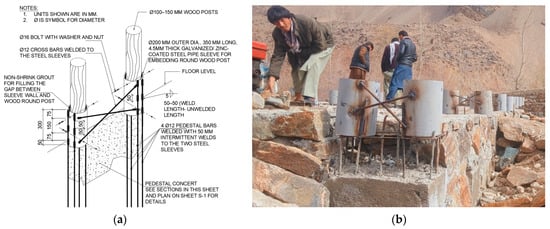
Figure 4.
Application of the proposed reinforcement and application technique in pilot project. (a) Proposed detail drawing, (b) application at site for house construction in Badakhshan, Afghanistan.
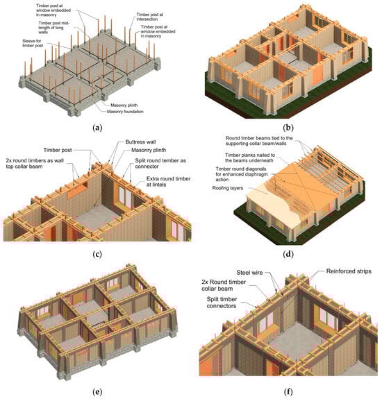
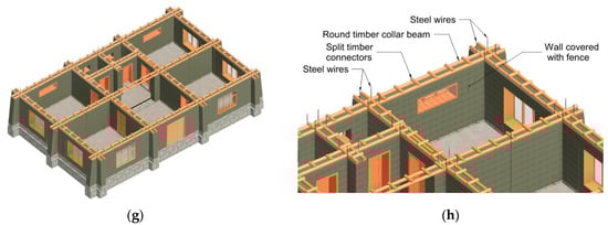
Figure 5.
Proposed timber-reinforced earthen model house (a–d), proposed flexible steel- or geogrid-reinforced earthen model house (e,f), proposed soft fence-reinforced earthen model house (g,h).
The roof can be easily tied to collar beams, which can in turn be attached to the vertical posts. This reinforcement technique relies on both mechanical interlock and frequent fastening with steel nails or wooden wedges, making it implementable in rural areas without requiring specialised skills or technology (Figure 5c). As the roof is attached to the vertical posts, they act as a frame that also provides secondary support to the roof in case the wall collapses. It is important to note that this technique is intended solely for new earthen construction.
8.3.2. Flexible Steel Mesh- or Geogrid-Reinforced Earthen Building
Flexible steel mesh is a viable and favourable option for reinforcing earthen houses in Afghanistan. Therefore, the second proposed reinforcement option for the model house involves the use of flexible steel mesh or geogrid with radial secant stiffness of at least 290 kN/m at 2% strain and a tensile strength of 20 to 30 kN/m (according to NZS 4298). This mesh can be used to partially cover earthen walls both horizontally and vertically, corresponding to beams and columns, respectively (Figure 5e,f).
At the corners, 4 mm diameter steel wires can be passed through the wall at both the bottom and the top over the collar beam. This method is effective for shaping the mesh, tying the collar beam to the wall, and enhancing the composite action between the wall, roof, and collar beam. For existing buildings that are to be retrofitted, the mesh on both sides can be secured with steel wires inserted through narrow holes. In new constructions, horizontal strips of mesh can be added at a maximum vertical spacing of 500 mm at horizontal mortar joints, which can then be tied to mesh strips on both sides of the wall surfaces.
The mesh should be applied at key points, such as the intersections of walls, free ends, both sides of door and window openings, and the middle of long walls (Figure 5e,f). It is essential to tie the mesh at the base of the existing wall or at the bottom of the masonry plinth in new constructions. The reinforced bands should ideally be plastered with lime-sand plaster; however, the application of mud plaster may be considered as a last resort and is less favourable.
At the top, the mesh can be wrapped around the wooden collar beam and fastened using timber secured with steel nails. The roof can be constructed using round wooden beams, like the timber reinforcement option discussed earlier. The foundation can also follow the design outlined in the previous section for reinforced timber.
8.3.3. Soft Plastic Fence-Reinforced Earthen Building
Soft plastic fencing is weaker in tension compared to steel or geogrid mesh; however, it is affordable and easily accessible. Therefore, the third option proposed by the author is the use of soft plastic fencing for completely covering the walls on both faces. At the corners, 4 mm diameter steel wires can be passed through the wall at both the bottom and the top over the collar beam (Figure 5g,h). This method is effective for shaping the mesh, tying the collar beam to the wall, and enhancing the composite action between the wall, roof, and collar beam.
The mesh on both sides of the walls can be secured to each other using steel or nylon strings at appropriate spacings of 400 to 600 mm in both directions. By fully covering the wall with mesh, this option can be particularly effective in preventing collapse by holding the blocks of the damaged wall together. The mesh shall be covered with mud or preferably lime-sand plaster. The roof and foundation can be detailed similarly to the timber-reinforced option.
9. Future Work
The proposed specifications and reinforcement details for an earthquake-resistant earthen model house were developed through a comprehensive review of experimental studies, codes, standards, and normative documents. While the resulting recommendations generally satisfy or exceed established requirements, several gaps remain that require targeted research and validation.
A major limitation is the absence of experimental evidence on full-scale earthen buildings with wall thicknesses typical in Afghanistan (350 mm or more). None of the reviewed studies examined how reinforcement systems perform when anchored simultaneously to the foundation and to a collar beam or roof in thick-wall adobe or Pakhsa construction. This is a critical knowledge gap, as anchorage quality strongly influences global stability, rocking suppression, and out-of-plane resistance. Furthermore, the recommendations for Pakhsa buildings rely on research conducted on rammed earth walls, which share similarities but may differ in compaction, joint behaviour, and crack propagation. Dedicated testing of Pakhsa assemblies is therefore essential.
Future work should prioritise shake table testing of full-scale adobe and Pakhsa structures constructed with locally representative geometries, roof loading conditions, and boundary restraints. These tests should explicitly evaluate the following:
- (1)
- Foundation-to-roof anchorage of reinforcement;
- (2)
- Concentrated flat-roof loading and diaphragm action;
- (3)
- Corner and wall intersection behaviour;
- (4)
- Performance of the three reinforcement options proposed in this study (timber, flexible steel mesh or geogrid, and soft plastic fencing).
Such verification is necessary to confirm performance in regions of differing seismic intensity. The proposed systems may be conservative in areas of lower hazard yet under-detailed for high-intensity regions; therefore, refinement of reinforcement density, anchorage detailing, and material combinations should form part of the validation programme. Additional exploration of low-cost materials—such as plastic rope or hybrid layouts combining features from multiple reinforcement systems—may yield more efficient alternatives.
Beyond technical research, institutional capacity remains a major obstacle to im-proving seismic safety in Afghan earthen construction. Strengthening governmental, academic, and professional institutions is essential for developing, updating, and enforcing earthen building standards. Capacity-building initiatives, collaborative programmes with international research groups, and the establishment of national testing and certification facilities would materially advance the reliability and uptake of new design provisions. A cost-benefit analysis of the reinforcement options will further support practical decision-making and encourage adoption among resource-limited communities.
By addressing these technical and institutional gaps, future work can substantiate and optimise the proposed reinforcement strategies and contribute to a robust, context-appropriate framework for earthquake-resistant earthen construction in Afghanistan.
10. Conclusions
A substantial proportion of Afghanistan’s population lives in adobe and Pakhsa dwellings that are highly vulnerable to seismic events. Recurrent earthquakes continue to cause large numbers of casualties, severe economic losses in already fragile communities, and long-lasting psychological impacts. In the absence of national regulations or enforcement mechanisms governing the seismic design of earthen construction, most buildings remain unprotected against earthquake-induced damage.
This study reviewed experimental research, seismic codes, standards, and normative documents to identify context-appropriate measures for improving the earthquake performance of Afghan earthen buildings. Drawing on this evidence, we developed a set of specifications and detailing recommendations for an earthquake-resistant earthen model house intended to serve as a practical benchmark for adobe and Pakhsa construction in Afghanistan.
The proposed model aligns with local conditions by incorporating material availability, cost constraints, vernacular building practices, and the workmanship typically found in rural and remote regions. It focuses on the two main wall systems used locally—adobe brick and Pakhsa—and integrates reinforcement strategies demonstrated in the literature to enhance in-plane strength, out-of-plane stability, ductility, and collapse prevention. The model includes three reinforcement options: (i) timber elements used as whole round logs; (ii) flexible steel wire mesh or geogrid; and (iii) soft plastic fencing tied across both wall faces. These alternatives improve adaptability under varying material availability and economic conditions, while maintaining compatibility with local construction methods.
The model house synthesises provisions from international codes—such as Norma E.080 [75], NBC 204 [76], IS 13827 [80], the IAEE Guidelines [81], the Afghanistan 2003 Guidelines [24], and NZS 4297–4299 [77,78,79]—together with reinforcement techniques validated through laboratory and full-scale testing. Adjustments were made to ensure suitability for Afghan wall geometries, concentrated flat-roof loading, and traditional construction sequences, emphasising clarity and feasibility for field implementation.
Further validation through experimental or numerical studies will be essential to confirm the seismic performance of the proposed reinforcement strategies when applied to thick Afghan adobe and Pakhsa walls. Such efforts would support the development of a modern national guideline tailored to local materials, structural typologies, and seismic hazard conditions. The reinforced adobe and Pakhsa model house presented here is intended as an initial step toward establishing practical, evidence-based standards that can meaningfully reduce earthquake risk for Afghanistan’s widespread earthen building stock.
Author Contributions
Conceptualisation, M.M.; methodology, M.M.; validation, M.M.; formal analysis, M.M.; investigation, M.M.; resources, A.J.R.; data curation, M.M.; writing—original draft preparation, M.M.; writing—review and editing, A.J.R.; visualisation, M.M.; supervision, A.J.R.; project administration, M.M.; funding acquisition, A.J.R. All authors have read and agreed to the published version of the manuscript.
Funding
The APC was funded by the University of Bath.
Data Availability Statement
The original contributions presented in this study are included in the article. Further inquiries can be directed to the corresponding author.
Conflicts of Interest
The authors declare no conflicts of interest.
Appendix A
Table A1.
Summary of properties of test specimens reviewed—loading and specimens.
Table A1.
Summary of properties of test specimens reviewed—loading and specimens.
| No | Test Loading Type | Construction Type | Sample Size (L × B × H) * | Wall t * (mm) | Axial Load | Ref. |
|---|---|---|---|---|---|---|
| 1 | Tilting platform | Adobe building model | 3.3 × 3.3 × 1.8 | 280 | - | [48] |
| 2 | Shake table | Adobe building model | 3.25 × 3.25 × 2.4 | 300 | Roof | [50] |
| 3 | Shake table | U-shaped adobe wall | 3.3 × 1.2 × 1.8 | 280 | - | [52] |
| 4 | Shake table | Adobe building model | 3.3 × 3.3 × 1.8 | 280 | Roof | [53] |
| 5 | Cyclic tests | I-shaped adobe wall | 3.06 × 2.4 × 1.93 | 300 | Crown beam | [55] |
| 6 | Cyclic tests | I-shaped adobe wall | 3.06 × 2.4 × 1.93 | 300 | Crown beam | [55] |
| 7 | Cyclic tests | I-shaped adobe wall | 3.06 × 2.4 × 1.93 | 300 | Crown beam | [55] |
| 8 | Cyclic tests | I-shaped adobe wall | 3.06 × 2.4 × 1.93 | 300 | Crown beam | [55] |
| 9 | Cyclic tests | I-shaped adobe wall | 3.06 × 2.4 × 1.93 | 300 | Crown beam | [55] |
| 10 | Shake table | Full-scale adobe house model | 3.25 × 3.25 × 2.25 | 260 | Roof | [56] |
| 11 | Shake table | Full-scale adobe house model | 3.25 × 3.25 × 2.25 | 260 | Roof | [56] |
| 12 | Shake table | Full-scale adobe house model | 3.25 × 3.25 × 2.25 | 260 | Roof | [56] |
| 13 | Shake table | Full-scale adobe house model | 3.25 × 3.25 × 2.25 | 260 | Roof | [56] |
| 14 | Diag. compression | Adobe wall panel | 0.8 × 0.8 × 0.105 | 105 | Edge load | [57] |
| 15 | Diag. compression | Adobe wall panel | 0.8 × 0.8 × 0.105 | 105 | Edge load | [57] |
| 16 | Diag. compression | Adobe wall panel | 0.8 × 0.8 × 0.105 | 105 | Edge load | [57] |
| 17 | Cyclic loading | Adobe wall panel | 1 × 0.9 × 0.20 | 200 | 0.3 MPa | [58] |
| 18 | Cyclic loading | Adobe wall panel | 1 × 0.9 × 0.20 | 200 | 0.3 MPa | [58] |
| 19 | Cyclic loading | Adobe wall panel | 1 × 0.9 × 0.20 | 200 | 0.3 MPa | [58] |
| 20 | Cyclic loading | Adobe wall panel | 1 × 0.9 × 0.20 | 200 | 0.3 MPa | [58] |
| 21 | Cyclic loading | Adobe wall panel | 1 × 0.9 × 0.20 | 200 | 0.3 MPa | [58] |
| 22 | Cyclic loading | Adobe wall panel | 1 × 0.9 × 0.20 | 200 | 0.3 MPa | [58] |
| 23 | Cyclic loading | Adobe wall panel | 1 × 0.9 × 0.20 | 200 | 0.3 MPa | [58] |
| 24 | Cyclic loading | Adobe wall panel | 1 × 0.9 × 0.20 | 200 | 0.3 MPa | [58] |
| 25 | Cyclic loading | Adobe wall panel | 1.05 × 1.37 × 0.24 | 240 | 0.32 MPa | [59] |
| 26 | Cyclic loading | Adobe wall panel | 1.05 × 1.37 × 0.24 | 240 | 0.32 MPa | [59] |
| 27 | Cyclic loading | Adobe wall panel | 1.05 × 1.37 × 0.24 | 240 | 0.32 MPa | [59] |
| 28 | Cyclic loading | Double T-shaped adobe wall | 3.5 × 3.07 × 0.29 | 290 | 20 kN | [60] |
| 29 | Cyclic loading | Adobe wall panel | 1.02 × 0.80 × 0.2 | 200 | 0.1 MPa | [61] |
| 30 | Cyclic loading | Adobe wall panel | 1.02 × 0.80 × 0.2 | 200 | 0.1 MPa | [61] |
| 31 | Cyclic loading | Adobe wall panel | 1.02 × 0.80 × 0.2 | 200 | 0.1 MPa | [61] |
| 32 | Cyclic loading | Adobe wall panel | 1.02 × 0.80 × 0.2 | 200 | 0.3 MPa | [61] |
| 33 | Cyclic loading | Adobe wall panel | 1.02 × 0.80 × 0.2 | 200 | 0.3 MPa | [61] |
| 34 | Cyclic loading | Adobe wall panel | 2.50 × 1.80 × 0.40 | 400 | 70 kN | [62] |
| 35 | Cyclic loading | Adobe wall panel | 2.50 × 1.80 × 0.40 | 400 | 50 kN | [62] |
| 36 | Cyclic loading | Adobe wall panel | 2.50 × 1.80 × 0.40 | 400 | 20 kN | [62] |
| 37 | Cyclic loading | RE wall | 2.50 × 1.80 × 0.40 | 400 | 70 kN | [62] |
| 38 | Cyclic loading | RE wall | 2.50 × 1.80 × 0.40 | 400 | 50 kN | [62] |
| 39 | Cyclic loading | RE wall | 2.50 × 1.80 × 0.40 | 400 | 20 kN | [62] |
| 40 | Shake table (out-of-plane) | L-shaped RE corner wall | (3.0,1.8) × 3.45 × 0.60 | 600 | 21 kN | [62] |
| 41 | Shake table (out-of-plane) | L-shaped RE corner wall | (3.0,1.8) × 3.45 × 0.60 | 600 | 21 kN | [62] |
| 42 | Shake table (out-of-plane) | L-shaped RE corner wall | (3.0,1.8) × 3.45 × 0.60 | 600 | 21 kN | [62] |
| 43 | Cyclic tests | Adobe wall pier | 1.25 × 2.35 × 0.60 | 600 | 0.02 MPa | [63] |
| 44 | Cyclic tests (out-of-plane) | Adobe wall pier | 1.25 × 2.35 × 0.60 | 600 | 0.02 MPa | [63] |
| 45 | Unidir. shaking (out-of-plane) | L-shaped RE corner wall pier | (3.0,1.8) × 3.45 × 0.60 | 600 | 0.008 MPa | [63] |
| 46 | Monotonic lateral load | RE wall panel | 2.4 × 2.1 × 0.6 | 600 | 0.06 MPa | [64] |
| 47 | Static out-of-plane overturning | Adobe wall panel | 2.7 × 1.8 × 0.4 | 400 | - | [65] |
| 48 | Shake table (out-of-plane) | L-shaped adobe corner wall | (3.0,1.8) ×3.45 × 0.60 | 600 | 0.008 MPa | [65] |
| 49 | Shake table (out-of-plane) | L-shaped adobe corner wall | (3.0,1.8) ×3.45 × 0.60 | 600 | 0.008 MPa | [65] |
| 50 | Out-of-plane static pull-down | Full-scale U-shaped RE walls | (5.4,2.7) × 2.4 × 0.60 | 600 | - | [66] |
| 51 | Out-of-plane static pull-down | Full-scale U-shaped RE walls | (5.4,2.7) × 2.4 × 0.60 | 600 | - | [66] |
| 52 | In-plane cyclic tests | RE wall | 1.050 × 1.31 × 0.25 | 250 | 0.56 MPa | [67] |
| 53 | Unidirectional shaking | Full-scale adobe house model | 3.25 × 3.25 × 2.25 | 250 | Roof | [68] |
| 54 | Cyclic loading | C-shaped adobe wall with opening | (5.8,1.5) × 3.45 × 0.60 | 600 | (5.2 kN/m) | [69] |
| 55 | Cyclic loading | RE walls with openings | (5.8,1.5) × 3.45 × 0.60 | 600 | (5.2 kN/m) | [69] |
| 56 | Shake table | 1:4 scale adobe house model | 0.93 × 0.93 × 0.72 | 50 | - | [70] |
| 57 | Unidirectional shake table | Full-scale adobe house model | 3.25 × 3.25 × 2.25 | 250 | Roof | [71] |
| 58 | Unidirectional shake table | Full-scale adobe house | 3.25 × 3.25 × 2.25 | 250 | Roof | [71] |
| 59 | Unidirectional shake table | Half-scale two-storey adobe house | 2.04 × 1.82 × 3.28 | 220 | Roof | [72] |
| 60 | Static cyclic in-plane | 1:1.25 scale I-shaped RE wall | (2.8,1.2) × 1.8 × 0.4 | 400 | 0.006 MPa | [73] |
| 61 | Dynamic out-of-plane | U-shaped RE wall | (2.8,1.2) × 1.8 × 0.4 | 500 | - | [74] |
* L = length, B = width, H = height for building models (3D specimens); L = Length, B = Height, H = wall thickness for wall panels (2D specimens); t = wall thickness.
Table A2.
Summary of properties of test specimens reviewed—materials.
Table A2.
Summary of properties of test specimens reviewed—materials.
| No | Adobe Materials | Comp. Strength (MPa) | Tensile Str. (MPa) | Adobe Jointing Mortar | Mortar Comp. Str. (MPa) | Mortar Tensile Strength (MPa) | Ref. |
|---|---|---|---|---|---|---|---|
| 1 | - | - | - | Mud mortar | - | - | [48] |
| 2 | 8:1 (clay soil-straw) | 2.4 | - | Mud mortar | 3.5 | - | [50] |
| 3 | - | - | - | Mud mortar | - | - | [52] |
| 4 | - | - | - | Mud mortar | - | - | [53] |
| 5 | - | - | - | Mud mortar | - | - | [55] |
| 6 | - | - | - | Mud mortar | - | - | [55] |
| 7 | - | - | - | Mud mortar | - | - | [55] |
| 8 | - | - | - | Mud mortar | - | - | [55] |
| 9 | - | - | - | Mud mortar | - | - | [55] |
| 10 | 5:1:1 (soil-sand-straw) | - | - | 3:1:1 (soil-sand-straw) | - | - | [56] |
| 11 | 5:1:1 (soil-sand-straw) | - | - | 3:1:1 (soil-sand-straw) | - | - | [56] |
| 12 | 5:1:1 (soil-sand-straw) | - | - | 3:1:1 (soil-sand-straw) | - | - | [56] |
| 13 | 5:1:1 (soil-sand-straw) | - | - | 3:1:1 (soil-sand-straw) | - | - | [56] |
| 14 | 1.86:1 (soil-sand) | - | - | 1.86:1 (soil-sand) | 4 | 0.039 | [57] |
| 15 | 6.4:3.5:0.1 (soil-sand-straw) | - | - | 1.86:1 (soil-sand) | 4 | 0.039 | [57] |
| 16 | 5.9:3.1:1 (soil-sand-fly ash) | - | - | 1.86:1 (soil-sand) | 4 | 0.039 | [57] |
| 17 | 1:1 (soil-sand) | 4.43 | - | 1:1 (soil-sand) | 3.31 | 0.52 (direct) | [58] |
| 18 | 1:1 (soil-sand) | 4.43 | - | 1:1 (soil-sand) | 3.31 | 0.52 (direct) | [58] |
| 19 | 1:1 (soil-sand) | 4.43 | - | 1:1 (soil-sand) | 3.31 | 0.52 (direct) | [58] |
| 20 | 1:1 (soil-sand) | 4.43 | - | 1:1 (soil-sand) | 3.31 | 0.52 (direct) | [58] |
| 21 | 1:1 (soil-sand) | 4.43 | - | 1:1 (soil-sand) | 3.31 | 0.52 (direct) | [58] |
| 22 | 1:1 (soil-sand) | 4.43 | - | 1:1 (soil-sand) | 3.31 | 0.52 (direct) | [58] |
| 23 | 1:1 (soil-sand) | 4.43 | - | 1:1 (soil-sand) | 3.31 | 0.52 (direct) | [58] |
| 24 | 1:1 (soil-sand) | 4.43 | - | 1:1 (soil-sand) | 3.31 | 0.52 (direct) | [58] |
| 25 | - | 5.1 | 0.5 | Adobe mortar | 3.16 | 0.3 | [59] |
| 26 | - | 5.1 | 0.5 | Adobe mortar | 3.16 | 0.3 | [59] |
| 27 | - | 7.5 | 0.82 | Adobe mortar | 3.16 | 0.3 | [59] |
| 28 | - | 0.46 | 0.15 | 1:1:2 (lime-soil-sand) | 0.67 | 0.23 | [60] |
| 29 | - | 4.43 | - | 1:1 (soil-sand) | 3.31 | 0.52 (direct) | [61] |
| 30 | - | 4.43 | - | 1:1 (soil-sand) | 3.31 | 0.52 (direct) | [61] |
| 31 | - | 4.43 | - | 1:1 (soil-sand) | 3.31 | 0.52 (direct) | [61] |
| 32 | - | 4.43 | - | 1:1 (soil-sand) | 3.31 | 0.52 (direct) | [61] |
| 33 | - | 4.43 | - | 1:1 (soil-sand) | 3.31 | 0.52 (direct) | [61] |
| 34 | - | 2.85 | 0.028 (diag.) | 1:2 (lime-sand) | 2.5 | 0.147 | [62] |
| 35 | - | 2.85 | 0.028 (diag.) | 1:2 (lime-sand) | 2.5 | 0.147 | [62] |
| 36 | - | 2.85 | 0.028 (diag.) | 1:2 (lime-sand) | 2.5 | 0.147 | [62] |
| 37 | - | 1.11 | 0.032 (diag.) | - | - | - | [62] |
| 38 | - | 1.11 | 0.032 (diag.) | - | - | - | [62] |
| 39 | - | 1.11 | 0.032 (diag.) | - | - | - | [62] |
| 40 | - | 1.11 | 0.032 (diag.) | - | - | - | [62] |
| 41 | - | 1.11 | 0.032 (diag.) | - | - | - | [62] |
| 42 | - | 1.11 | 0.032 (diag.) | - | - | - | [62] |
| 43 | - | 2.782 | 0.028 (diag.) | Mud mortar | - | - | [63] |
| 44 | - | 2.782 | 0.028 (diag.) | Mud mortar | - | - | [63] |
| 45 | - | 1.1 | 0.035 (diag.) | - | 1.1 (Wallette) | 0.035 diagonal | [63] |
| 46 | - | 1.36 | - | - | - | - | [64] |
| 47 | Low-plasticity clay (CL) | 2.8 | 0.028 (diag.) | - | - | - | [65] |
| 48 | Low-plasticity clay (CL) | 2.8 | 0.028 (diag.) | Mud mortar | - | - | [65] |
| 49 | Low-plasticity clay (CL) | 2.8 | 0.028 (diag.) | Mud mortar | - | - | [65] |
| 50 | - | 2.8 | 0.05 | - | - | - | [66] |
| 51 | - | 2.8 | 0.05 | - | - | - | [66] |
| 52 | - | 2.8 | - | - | - | - | [67] |
| 53 | 5:1:1 (soil-sand-straw) | 2.8 | - | 3:1:1 (soil-sand-straw) | - | - | [68] |
| 54 | Low-plasticity clay (CL) | 2.8 | 0.028 (diag.) | Mud mortar | - | - | [69] |
| 55 | - | 1.1 | 0.031 (diag.) | - | - | - | [69] |
| 56 | 1:4:7 (sand-clay-ceramic) | 4.28 | 1:3:9 (cem-lime-sand) | [70] | |||
| 57 | 5:1:1 (soil-straw-sand) | - | - | 3:1:1 (soil-straw-sand) | - | - | [71] |
| 58 | 5:1:1 (soil-straw-sand) | - | - | 3:1:1 (soil-straw-sand) | - | - | [71] |
| 59 | 5:1:1 (soil-straw-sand) | 1.07 | 0.044 | 1:1 (soil-coarse sand) | - | - | [72] |
| 60 | 1:1.5:6:8 (clay-silt-sand-gravel) | 0.56 | - | - | - | - | [73] |
| 61 | 1:1.5:6:8 (clay-silt-sand-gravel) | 0.56 | - | - | - | - | [74] |
Table A3.
Summary of reinforcement types and materials reviewed in the journal papers.
Table A3.
Summary of reinforcement types and materials reviewed in the journal papers.
| No | Type | Attachment to Wall | Connection on Both Sides of Wall | Wall Cover Plaster | Mesh Size (mm) | Thread Size (mm) | Reinf.t Tensile Strength | Ref |
|---|---|---|---|---|---|---|---|---|
| 1 | Bamboo mesh | - | - | - | 450 × 340 | - | - | [48] |
| 2 | Bamboo mesh | - | - | - | 450 × 340 | - | - | [50] |
| 3 | Steel wire mesh | Nailed to wall | Metal bars at 500 mm | Cement-sand (1:4) | 19 × 19 | 1 mm | - | [52] |
| 4 | Steel wire mesh | Nailed to wall | Metal bars at 500 mm | Cement-sand (1:4) | 19 × 19 | 1 mm | - | [53] |
| 5 | Cane mesh | - | - | - | 450 × 410 | 19 mm | 10 kN | [55] |
| 6 | Plastic mesh | - | - | - | - | 19 mm | 3.0 kN | [55] |
| 7 | Steel wire mesh | Nailed to wall | Metal bars at 500 mm | Cement-sand (1:4) | - | - | - | [55] |
| 8 | Geogrid | Plastic strings | - | - | - | - | 20 kN/m | [55] |
| 9 | Steel bars | - | - | - | - | - | - | [55] |
| 10 | Geogrid | - | Plastic string | Mud plaster | 33 × 33 | 1.27 | 29 kN/m | [56] |
| 11 | Geogrid | - | Plastic string | Mud plaster | 33 × 33 | 0.76 | 19 kN/m | [56] |
| 12 | Geogrid | - | Plastic string | Mud plaster | 33 × 33 | 0.76 | 19 kN/m | [56] |
| 13 | Soft plastic fence | - | Plastic string | Mud plaster | - | - | 1.4 kN/m | [56] |
| 14 | Plaster mesh | - | - | - | 5 × 5 | - | - | [57] |
| 15 | Plaster mesh | - | - | - | 5 × 5 | - | - | [57] |
| 16 | Plaster mesh | - | - | - | 5 × 5 | - | - | [57] |
| 17 | Palm mesh | - | - | Straw-clay | 100 × 100 | 5 | 4.6 kN/m | [58] |
| 18 | Palm mesh | - | 5 ϕ 5 mm palm ropes | Straw-clay (1:0.05) | 100 × 100 | 5 | 4.6 kN/m | [58] |
| 19 | Palm mesh | - | 9 ϕ 5 mm palm ropes | Straw-clay (1:0.05) | 100 × 100 | 5 | 4.6 kN/m | [58] |
| 20 | Palm mesh | - | 5 ϕ 5 mm palm ropes | Straw-clay (1:0.05) | 50 × 50 | 5 | 5.5 kN/m | [58] |
| 21 | Palm mesh | - | 5 ϕ 5 mm palm ropes | Straw-clay (1:0.05) | 50 × 50 | 5 | 5.5 kN/m | [58] |
| 22 | HDPE mesh | - | 5 ϕ 3 mm plastic wire | Straw-clay (1:0.05) | 55 × 55 | 3 | 3.9 kN/m | [58] |
| 23 | Palm ropes | - | 12 ϕ 5 mm palm ropes | Straw-clay (1:0.05) | - | 12 | 20.7 MPa | [58] |
| 24 | Reed | - | 12 ϕ 5 mm palm ropes | Straw-clay (1:0.05) | - | 15 | 88 MPa | [58] |
| 25 | Steel wire ropes | End screws | - | Adobe plaster | - | 4 | 1770 MPa | [59] |
| 26 | PE geonet | U-steel staple | - | Adobe plaster | 25 × 25 | - | 38 kN/m | [59] |
| 27 | PP geonet | U-steel staple | - | Adobe plaster | 30 × 45 | - | 17 kN/m | [59] |
| 28 | Plastic mesh | plastic plugs | Nylon threads | Lime plaster | 15 × 20 | 0.8 × 0.6 | 9 MPa | [60] |
| 29 | Steel rebars | - | Steel wires | Cement-sand (1:2) | - | 8 | 420 MPa | [61] |
| 30 | Steel rebars | - | Steel wires at four points | - | - | 8 | 420 MPa | [61] |
| 31 | Steel rebars | - | Steel wires at nine points | - | - | 8 | 420 MPa | [61] |
| 32 | Steel rebars | - | Steel wires | Cement-sand (1:2) | - | 8 | 420 MPa | [61] |
| 33 | Steel rebars | - | Steel wires | - | - | 8 | 420 MPa | [61] |
| 34 | Steel wire mesh | Nailed at 0.3m | Steel wires at 0.5 m | Stucco | 25 × 25 | 0.91 | 13.5 kN/m | [62] |
| 35 | Steel wire mesh | Nailed at 0.3m | Steel wires at 0.5 m | Stucco | 25 × 25 | 0.91 | 13.5 kN/m | [62] |
| 36 | Steel wire mesh | Nailed at 0.3m | Steel wires at 0.5 m | Stucco | 25 × 25 | 0.91 | 13.5 kN/m | [62] |
| 37 | Steel wire mesh | Nailed at 0.3m | Steel wires at 0.5 m | Stucco | 25 × 25 | 0.91 | 13.5 kN/m | [62] |
| 38 | Steel wire mesh | Nailed at 0.3m | Steel wires at 0.5 m | Stucco | 25 × 25 | 0.91 | 13.5 kN/m | [62] |
| 39 | Steel wire mesh | Nailed at 0.3m | Steel wires at 0.5 m | Stucco | 25 × 25 | 0.91 | 13.5 kN/m | [62] |
| 40 | Steel wire mesh | - | Steel bolts at 0.5 m | Lime mortar | 150 × 150 | 6 | 90 kN/m | [62] |
| 41 | Polyester geogrid | - | Steel bolts at 0.5 m | Lime mortar | 60 × 40 | 30 × 20 | 306 kN/m | [62] |
| 42 | PP geogrid | - | Steel bolts at 0.5 m | Lime mortar | 35 × 35 | 4 × 4 | 12.9 kN/m | [62] |
| 43 | A36 steel plates | - | 9.5 mm steel rods | Uncovered | 1200 × 1200 | 6.4 × 101 | 293 MPa | [63] |
| 44 | A36 steel plates | - | 9.5 mm steel rods | Uncovered | 1200 × 1200 | 6.4 × 101 | 293 MPa | [63] |
| 45 | A36 steel plates | - | 9.5 mm steel rods | Uncovered | 1200 × 1200 | 6.4 × 101 | 293 MPa | [63] |
| 46 | Tarpaulin strips | NF adhesive | - | Mud plaster | - | 0.83 | 49.03 MPa | [64] |
| 47 | Timber elements | - | 7.94 mm bolts | - | - | 150 × 20 | 40 MPa | [65] |
| 48 | Timber elements | - | 7.94 mm bolts | - | - | 200 × 40 | 40 MPa | [65] |
| 49 | Timber elements | - | 7.94 mm bolts | - | - | 200 × 40 | 40 MPa | [65] |
| 50 | Steel mesh | - | Horizontal timbers | Stabilised earth | 28 × 28 | 1.45 | 396 MPa | [66] |
| 51 | Timber frame | - | Horizontal timbers | - | - | 150 × 150 | 62.08 MPa | [66] |
| 52 | Polyester strips | Ceme. mortar | - | - | 50 × 3 | 40 MPa | [67] | |
| 53 | Geogrid | - | Plastic strings—0.25 m | Mud-straw | 33 × 33 | 0.76 | 13.5 kN/m | [68] |
| 54 | Timber planks | - | 7.94 mm bolts | Uncovered | - | 180 × 40 | 40 MPa | [69] |
| 55 | Timber planks | - | 7.94 mm bolts | Uncovered | - | 180 × 40 | 40 MPa | [69] |
| 56 | PE band mesh | - | Wires every 160 mm | Adobe plaster | 40 × 40 | 6 × 0.32 | 181 MPa | [70] |
| 57 | Nylon rope mesh | - | 3 mm nylon ropes | - | 250 × 250 | 6 mm | 2 kN | [71] |
| 58 | Nylon rope mesh | - | 3 mm nylon ropes | - | 125 × 125 | 3 mm | 0.7 kN | [71] |
| 59 | Nylon rope mesh | - | 3 mm nylon ropes | Mud stucco | 125 × 110 | 3 mm | 1.3 kN | [72] |
| 60 | Geo-mesh | Plastic plugs | Φ14 mm tie rods | Earth mortar | 22 × 25 | 1 × 3.09 | 42.08 kN/m | [73] |
| 61 | Nylon mesh | Plastic plugs | Nylon strings | Earth mortar | 16 × 21 | 1.12 | 3.18 kN/m | [74] |
Table A4.
Summary of reinforcement application techniques reviewed in the journal papers.
Table A4.
Summary of reinforcement application techniques reviewed in the journal papers.
| No | One-Line Description of the Reinforcement/Strengthening Technique of Test Specimen | Ref |
|---|---|---|
| 1 | Whole bamboo placed vertically at 1.5× wall thickness; split canes every 4th adobe block horizontally | [48] |
| 2 | Whole bamboo placed vertically at 1.5× wall thickness; split canes every 4th adobe block horizontally | [50] |
| 3 | 45 cm wide welded wire mesh strips placed vertically at critical points and horizontally at wall top | [52] |
| 4 | 45 cm wide welded wire mesh strips placed vertically at critical points and horizontally at wall top | [53] |
| 5 | Vertical cane rods and horizontal crushed cane integrated within the mortar every four layers | [55] |
| 6 | Vertical PVC pipes anchored to footing and crown; horizontal plastic mesh in mortar every four layers | [55] |
| 7 | Steel welded wire mesh was nailed to the wall and covered with cement mortar | [55] |
| 8 | External geosynthetic mesh had an elastic stiffness of 250 kN/m | [55] |
| 9 | Reinforcement consisting of single steel reinforcement bars at each corner | [55] |
| 10 | 100% of total wall surface covered by Tensar BX1200 mesh connected to wooden crown beam | [56] |
| 11 | 75% of total wall surface covered by Tensar BX1100 mesh connected to wooden crown beam | [56] |
| 12 | 50% of total wall surface covered by Tensar BX1100 mesh connected to wooden crown beam | [56] |
| 13 | 80% of total wall surface covered by soft fence mesh connected to wooden crown beam | [56] |
| 14 | Mesh placed between the horizontal mortar joints of the adobe blocks with no additives | [57] |
| 15 | Plastic plaster reinforcement mesh between horizontal mortar joints of adobe blocks with 1% straw | [57] |
| 16 | Plastic plaster reinforcement mesh between horizontal mortar joints of adobe blocks with 10% fly ash | [57] |
| 17 | Palm mesh with rectangular arrangement and not tied on both sides of wall | [58] |
| 18 | Palm mesh with rectangular arrangement and tied on both sides of wall; holes filled with mud mortar | [58] |
| 19 | Palm mesh with rectangular arrangement and tied on both sides of wall; holes filled with mud mortar | [58] |
| 20 | Mesh with rectangular arrangement; holes filled with mud mortar | [58] |
| 21 | Mesh with rhombus arrangement; holes filled with mud mortar | [58] |
| 22 | Plastic mesh with rectangular arrangement; holes filled with mud mortar | [58] |
| 23 | Eight palm ropes (four per side) placed diagonally in 30 mm grooves at 150 mm, filled with gypsum-clay mortar | [58] |
| 24 | Eight palm ropes (four per side) placed diagonally in 30 mm grooves at 150 mm, filled with gypsum-clay mortar | [58] |
| 25 | Three 0.4 MPa pre-stressed steel wires placed diagonally into grooves on wall both sides, totalling twelve per wall | [59] |
| 26 | Soil stabilisation polyethylene mesh applied on both sides of wall using staples with 10 mm embedment | [59] |
| 27 | Polypropylene plaster reinforcement mesh applied on both sides of wall using staples with 10 mm embedment | [59] |
| 28 | Retrofitted by injecting hydraulic lime in cracks, fixing polymeric mesh to wall using PVC angle beads, profiles | [60] |
| 29 | Cracks filled with cement grout; wall retrofitted with two vertical and two horizontal ϕ8 rebars on each side | [61] |
| 30 | Strengthened with two vertical and two horizontal ϕ8 epoxy-coated rebars on each side | [61] |
| 31 | Strengthened with three vertical and three horizontal ϕ8 epoxy-coated rebars on each side | [61] |
| 32 | Cracks filled with cement grout; wall retrofitted with two vertical and two horizontal ϕ8 rebars on each side | [61] |
| 33 | Strengthened with two vertical and two horizontal ϕ8 epoxy-coated rebars on each side | [61] |
| 34 | Steel wire mesh placed on both faces of wall covering 0.75 m of wall length on both sides and top 0.45 m height | [62] |
| 35 | Steel wire mesh placed on both faces of wall covering 0.75 m of wall length on both sides and top 0.45 m height | [62] |
| 36 | Steel wire mesh placed on both faces of wall covering 0.75 m of wall length on both sides and top 0.45 m height | [62] |
| 37 | Steel wire mesh placed on both faces of wall covering 0.75 m of wall length on both sides and top 0.45 m height | [62] |
| 38 | Steel wire mesh placed on both faces of wall covering 0.75 m of wall length on both sides and top 0.45 m height | [62] |
| 39 | Steel wire mesh placed on both faces of wall covering 0.75 m of wall length on both sides and top 0.45 m height | [62] |
| 40 | Mesh placed on both faces of wall and connected to each other using 9.5 mm dia. bolts every 500 mm | [62] |
| 41 | Polyester geogrid placed on both faces of wall, connected to each other using 9.5 mm bolts every 500 mm | [62] |
| 42 | Polypropylene geogrid mesh placed on both faces of wall, connected to each other by 9.5 mm bolts every 0.5 m | [62] |
| 43 | Steel plates on both faces of earth walls connected by 9.53 mm rods spaced every 0.6 m; holes were not filled | [63] |
| 44 | Steel plates on both faces of earth walls connected by 9.53 mm rods spaced every 0.6 m; holes were not filled | [63] |
| 45 | Ten vertical A36 steel strips (five per side) were fixed at 1.0 m intervals on both faces of wall and secured to roof | [63] |
| 46 | Reference model retrofitted by double layers of tarpaulin strips of 20 cm width spaced at 18 cm horizontally | [64] |
| 47 | Vertical and horizontal timber elements applied on both faces of wall, creating a confined frame | [65] |
| 48 | A confined frame of vertical and horizontal timber elements and three pairs of vertical rods on both faces of wall | [65] |
| 49 | Vertical and horizontal timber elements and three pairs of vertical rods tied to foundation, fixed to both faces of wall | [65] |
| 50 | Walls wrapped with steel mesh on both sides with 200 mm overlapping length at joints and corners | [66] |
| 51 | Vertical and horizontal (75 × 50) timbers fixed to the wall faces, creating a timber frame | [66] |
| 52 | Vertical polyester strips inserted into 56 mm deep, 9 mm wide slits filled later with 3 mm layer of adhesive | [67] |
| 53 | Walls covered by Tensar BX4100 on each face with 0.4 m overlaps tied to footing and top timber collar beam | [68] |
| 54 | Vertical and horizontal timber planks applied on both faces of wall, with additional timber connectors | [69] |
| 55 | Vertical and horizontal timber planks applied on both faces of wall, with additional timber connectors | [69] |
| 56 | Polyethylene bands tied at intersection with plastic welder and to roof and foundation with steel wires | [70] |
| 57 | Mud injected into cracks, external mesh of nylon ropes applied; ropes were tensioned using metal turnbuckles | [71] |
| 58 | Mud injected into cracks and an external mesh of nylon ropes applied; ropes were tied by hand | [71] |
| 59 | Mud injected into cracks and an external mesh of nylon ropes applied; ropes were tied by hand | [72] |
| 60 | Two 1 m wide mesh bands with an extra tying system applied to damaged specimen on each side in a X shape | [73] |
| 61 | Damaged sample repaired by grout injection, embedding a nylon mesh in a 15 mm thick layer of earth mortar | [74] |
Table A5.
Differences (%) of studied performance parameters compared to unreinforced reference specimens.
Table A5.
Differences (%) of studied performance parameters compared to unreinforced reference specimens.
| No. | Elastic Stiffness | Lateral Load | Ductility | Peak Load Disp. | Ultimate Disp. | Energy Dissipation | Ref |
|---|---|---|---|---|---|---|---|
| 1 | - | - | - | - | - | - | [48] |
| 2 | - | - | - | - | - | - | [50] |
| 3 | - | - | - | - | - | - | [52] |
| 4 | - | - | - | - | - | - | [53] |
| 5 | −14.6 | 73.7 | - | 2200 | 102 | - | [55] |
| 6 | 4.9 | 39.5 | - | 2000 | 102 | - | [55] |
| 7 | 56.1 | 113.2 | - | 750 | 0 | - | [55] |
| 8 | −26.8 | 2.6 | - | 900 | 100 | - | [55] |
| 9 | −14.6 | 26.3 | - | 600 | 2 | - | [55] |
| 10 | - | - | - | - | - | - | [56] |
| 11 | - | - | - | - | - | - | [56] |
| 12 | - | - | - | - | - | - | [56] |
| 13 | - | - | - | - | - | - | [56] |
| 14 | - | 37.4 | - | - | 18.6 | 41.6 | [57] |
| 15 | - | 70.3 | - | - | 149.8 | 473.5 | [57] |
| 16 | - | 136.3 | - | - | 105.9 | 385.4 | [57] |
| 17 | 15.7 | 12.7 | 22.6 | 13 | 11.7 | 45.9 | [58] |
| 18 | 13.6 | 24.6 | 3.2 | 13 | 10.2 | 60.9 | [58] |
| 19 | 19.1 | 19.7 | 9.7 | 13 | 0 | 11.6 | [58] |
| 20 | 21.4 | 46.8 | 25.8 | 50 | 44.5 | 78.5 | [58] |
| 21 | 11.3 | 45.4 | 29 | 63 | 66.4 | 232.6 | [58] |
| 22 | −10 | 11 | 3.2 | 25 | 22.6 | 25.3 | [58] |
| 23 | 23.9 | 46.8 | −9.7 | 25 | −2.2 | −17.2 | [58] |
| 24 | 16.1 | 49.4 | 54.8 | 100 | 91.2 | 183.3 | [58] |
| 25 | −15.7 | 91.5 | −32.3 | 63.6 | 53.5 | - | [59] |
| 26 | −26.6 | 35.4 | −31.9 | 18.1 | 25.7 | - | [59] |
| 27 | −32.8 | 47.6 | −32.7 | 44 | 47.5 | - | [59] |
| 28 | - | 23.4 | - | - | 162 | - | [60] |
| 29 | 47.7 | 20 | 52 | 23 | 33 | 121.6 | [61] |
| 30 | 58.5 | 134 | 28 | 100 | 56 | 283.8 | [61] |
| 31 | 55.9 | 181 | 65 | 150 | 122 | 424.3 | [61] |
| 32 | −7.2 | 31 | 1 | 46.5 | 31 | 73 | [61] |
| 33 | 13.3 | 73 | 67 | 78.8 | 145 | 845.9 | [61] |
| 34 | - | 2.3 | - | 3 | - | - | [62] |
| 35 | - | 69.6 | - | 213.6 | - | - | [62] |
| 36 | - | 200 | - | 93.6 | - | - | [62] |
| 37 | - | 40.6 | - | −4.9 | - | - | [62] |
| 38 | - | 75.9 | - | 172.4 | - | - | [62] |
| 39 | - | 29.4 | - | 9.9 | - | - | [62] |
| 40 | - | - | - | - | 122.6 | - | [62] |
| 41 | - | - | - | - | 190 | - | [62] |
| 42 | - | - | - | - | 170 | - | [62] |
| 43 | - | 30.1 | - | 230 | 278.6 | 205.6 | [63] |
| 44 | - | 56 | - | 47.1 | 50.9 | 105.3 | [63] |
| 45 | - | - | - | - | - | - | [63] |
| 46 | - | 22.2 | - | −72 | 63 | - | [64] |
| 47 | 138.2 | - | - | - | [65] | ||
| 48 | - | - | - | - | - | - | [65] |
| 49 | - | - | - | - | - | - | [65] |
| 50 | 81.6 | 71.6 | - | 676 | - | 333.9 | [66] |
| 51 | 207.2 | 8.8 | - | 1226.9 | - | 214.7 | [66] |
| 52 | 57.7 | −42.7 | 119.4 | 119.4 | 300 | [67] | |
| 53 | 100 | 50 | - | - | - | - | [68] |
| 54 | - | 69.1 | - | - | 443.5 | 1066.7 | [69] |
| 55 | - | 71.4 | - | - | 338.8 | 700 | [69] |
| 56 | - | 11.7 | - | - | 1825 | 962.5 | [70] |
| 57 | - | - | - | - | - | - | [71] |
| 58 | - | - | - | - | - | - | [71] |
| 59 | - | - | - | - | - | - | [72] |
| 60 | −70.6 | −2.5 | 4.8 | - | 238.9 | 0 | [73] |
| 61 | - | −30 | - | - | 30 | - | [74] |
Table A6.
Short qualitative results of different earthquake-resistant reinforcement techniques investigated in the reviewed literature.
Table A6.
Short qualitative results of different earthquake-resistant reinforcement techniques investigated in the reviewed literature.
| No. | One-Line Qualitative Description of the Results | Ref |
|---|---|---|
| 1 | Deformation capacity and seismic strength was significantly enhanced | [48] |
| 2 | The technique was effective, preventing wall separation at corners and subsequent out-of-plane collapse | [50] |
| 3 | Unreinforced wall collapsed before being wood- and rope-reinforced, while wire mesh-reinforced wall did not collapse | [52] |
| 4 | Preventing collapse for a certain time could be achieved by reinforcing the weakest zones | [53] |
| 5 | This internal reinforcement can be very effective in preventing the collapse of adobe walls | [55] |
| 6 | Internal reinforcement inside the mortar can be made with natural (cane) or industrial materials (plastic) | [55] |
| 7 | External steel wire mesh leads to stronger/stiffer walls with unstable post-elastic response and brittle failure | [55] |
| 8 | For geogrid mesh, elastic behaviour was as with unreinforced wall, but cyclic response was excellent without losing strength and with stable hysteretic loops | [55] |
| 9 | The reinforcement did not seem to provide any benefit to the adobe walls | [55] |
| 10 | Moderate amounts of polymer mesh reinforcement strategically placed at critical locations can effectively prevent partial or total collapse of adobe buildings during severe earthquakes | [56] |
| 11 | Mud plaster over the mesh substantially increased stiffness and strength of wall. It also protected the mesh from UV radiation | [56] |
| 12 | Collapse did not happen; however, the brittle failure of the longitudinal walls showed that the amount of reinforcement (50%) was insufficient | [56] |
| 13 | The amount of reinforcement (80%) provided was barely adequate to prevent brittle failure/collapse. Mesh on both sides of walls should be tightly connected | [56] |
| 14 | Plaster reinforcement mesh increased friction along the horizontal joints of wall panels and thus resulted in increased strength, deformability, and energy absorption | [57] |
| 15 | Straw enhanced energy absorption and ultimate load capacities by acting as shear reinforcement | [57] |
| 16 | Fly ash as an additive caused brittle failure, and simply enhancing the mechanical properties of adobe blocks with additives will not significantly improve wall deformation capacity without mesh | [57] |
| 17 | The debonding of the reinforcing mesh from the wall surface resulted in poorer performance of this reinforcement. Straw-clay plaster had considerable effects on the lateral shear strength of walls | [58] |
| 18 | Reduced mesh dimensions were found to be very effective in enhancing the lateral performance of the adobe walls. Straw-clay plaster had significant effects on the ductility factor/displacement capacity | [58] |
| 19 | The increased number of anchors from five to nine increased their effectiveness | [58] |
| 20 | Reduced mesh dimensions were found to be very effective in enhancing the lateral performance of the adobe walls | [58] |
| 21 | Second greatest improvement in displacement capacity and ductility. The wall sustained higher numbers of hysteretic loops, showing the efficiency of the retrofitting | [58] |
| 22 | Compared to the plastic mesh, palm meshes of a similar grid size were found to be more effective in improving the lateral performance of adobe walls despite the higher tensile properties of the former | [58] |
| 23 | Reduced ductility shows the adverse effect of palm ropes on the ductility performance due to protrusion of the palm ropes outward in compression | [58] |
| 24 | Greatest improvement in lateral strength, wall sustained higher numbers of hysteretic loops. Lowest energy dissipation capacity from its rocking/toe crushing behaviour | [58] |
| 25 | Grooves for ropes reduced effective wall thickness and altered the load transfer mechanism, resulting in significant diagonal shear cracks and rapid failure of the entire specimen | [59] |
| 26 | Geonets and plaster detached easily and quickly from the wall surfaces, hindering load transfer to the geonets, showing connection between the strengthening elements and the wall is crucial | [59] |
| 27 | Polypropylene geonet outperformed polyethylene due to its greater rigidity and responsiveness under compression, enhancing load-carrying capacity and better distribution of tension forces | [59] |
| 28 | The retrofitting of an unreinforced damaged specimen markedly improved its performance, enhanced ductility and energy absorption, and resulted in greater resilience | [60] |
| 29 | The near-surface mounted (NSM) repair scheme restored the lateral loading and displacement capacities of the damaged walls and enhanced their structural performance | [61] |
| 30 | Dissipated energy was higher in the specimen exposed to 0.3 MPa than in the specimen exposed to 0.1 MPa | [61] |
| 31 | The ultimate strength and displacement capacities of the specimen with three vertical and three horizontal rebars were significantly greater than those with two | [61] |
| 32 | Increasing axial precompression from 0.1 to 0.3 MPa indicated that axial compression positively influences the displacement capacity of strengthened walls | [61] |
| 33 | Near-surface mounted (NSM) steel rebars were found to be more effective in enhancing deformation capacity than strength in walls subjected to high vertical loads | [61] |
| 34 | Higher axial loads provide increased confinement, making the contribution of the flexible steel welded wire mesh less significant in boosting the in-plane lateral load response of the walls | [62] |
| 35 | Axial compression increases the lateral load capacity of the reinforced wall, probably because of improved binding and shear interlock mechanisms | [62] |
| 36 | Steel welded wire mesh improved the overall lateral performance of adobe walls, but mostly under low axial loads, likely due to the substantial confinement provided by the mesh alone | [62] |
| 37 | Axial load shows no significant effect on drift capacity for moderate or near-collapse limit states in both wall types. The primary role of steel wire mesh is to prevent wall segment collapse | [62] |
| 38 | Flexible steel wire mesh does not prevent damage to walls but is effective in preventing local failures. No clear relationship between cracking drift and axial load is evident for retrofitted walls | [62] |
| 39 | The lateral load response of the rammed earth walls is enhanced with the steel welded wire mesh, but not as much as it was observed for the adobe walls | [62] |
| 40 | Meshes do not affect the initial lateral stiffness of the earthen walls; they influence the response only after walls crack/sustain structural damage especially under low to moderate axial loads | [62] |
| 41 | While meshes enhance the lateral load and displacement capacities of walls, preventing collapse and saving lives, they are insufficient to prevent excessive damage that may lead to demolition | [62] |
| 42 | For larger intensities, the differences between the three retrofitted specimens are not significant | [62] |
| 43 | The retrofitting demonstrated significantly less damage, despite exhibiting the same local drift values | [63] |
| 44 | Out-of-plane cyclic tests demonstrated a significant enhancement in the drift capacity of retrofitted piers, effectively avoiding typical brittle behaviour | [63] |
| 45 | Steel strips effectively supported out-of-plane demands, improved in-plane performance, delayed large crack formation, and minimised residual drifts and collapse | [63] |
| 46 | Failure of the reinforced wall was primarily shear failure, similar to that of the unreinforced wall | [64] |
| 47 | Retrofitting technique effectively confined earthen walls under out-of-plane forces | [65] |
| 48 | The timber retrofitting technique enhanced the out-of-plane integrity of adobe walls, prevented sudden collapse, and improved stiffness and re-centring capacity | [65] |
| 49 | Timber anchorage at foundation reduced rocking response and limited residual drifts | [65] |
| 50 | Mesh-wrapping delayed out-of-plane collapse and enhanced load distribution if it was connected at both wall faces to avoid detachment | [66] |
| 51 | Timber framing significantly disrupted the wall’s visual appearance and required special anchoring considerations for the vertical posts | [66] |
| 52 | Both in-plane and out-of-plane capacities of strengthened walls were higher than unstrengthened ones | [67] |
| 53 | Geogrid was torn near the window corners to the bottom corner of a wall due to stress concentrations. The plastered wall was minimally damaged, while the unplastered wall was severely impacted | [68] |
| 54 | After repairing the damaged walls with timber planks and vertical post-tensioning, the lateral stiffness of the original specimens was retained | [69] |
| 55 | The repair technique resulted in a 2.5-fold increase in displacement capacity and a 6-fold increase in energy dissipation with 70% increase in lateral load capacity | [69] |
| 56 | The PP-band mesh was effective in preserving structural integrity. Overall, the performance of the retrofitted models was at least three times better than that of non-retrofitted | [70] |
| 57 | The reinforcement held wall pieces together, preventing partial collapses and maintaining structural integrity | [71] |
| 58 | All walls broke down into large blocks, but the ropes prevented overturning and returned the pieces to their original locations. The structural integrity of the house was maintained | [71] |
| 59 | The rope reinforcement enhanced energy dissipation, lateral stiffness, and strength of the adobe walls, preserving structural integrity and preventing collapse | [72] |
| 60 | TRM strengthening solution effectively restored the original structure’s strength and enhanced its dissipative and ductility capacities. However, lateral stiffness was not recovered | [73] |
| 61 | The grout injection and nylon mesh strengthening could not restore pre-damage strength and improve hysteretic or damping capacity | [74] |
Table A7.
Summary of earthquake-resistant earthen building specifications from different standards, codes, or normative documents—part 1 [75,76,77,78,79].
Table A7.
Summary of earthquake-resistant earthen building specifications from different standards, codes, or normative documents—part 1 [75,76,77,78,79].
| Code | Parameter | Peru (Norma E.080 [75]) | Nepal (NBC 204 [76]) | New Zealand (NZS 4297–4299) [77,78,79] |
|---|---|---|---|---|
| Site and general requirements | Seismic zones | 1, 2, 3, 4 | - | 1, 2, 3 (buildings type 1 and 2) |
| Environmental protection | Plinth, coating and plasters, roof eaves, appropriate drainage | Damp-proof course, roof projections, site drainage, and plaster | Rain deflection, drainage, drying by damp-proof course, durable materials | |
| Height limit | One storey in zones 3 and 4 and two storeys in zones 1 and 2 | One storey plus an attic with 1.8 to 2.5 m storey height limitation | One storey detached with 600 m2 floor area with up to 3.6 m wall height | |
| Building shape | Rectangular symmetric/curved walls allowed | Symmetrical/regular with 3:1 length-to-breath ratio | Rectangular | |
| Construction on slopes | - | Provision provided for allowed slopes ≤20° | Detailed provisions provided | |
| Avoid earthen building construction in zones of and that are prone to: | Floods, landslides and debris flows, instability | Landslides, erosion, liquefaction, fault proximity, riverbanks, marshy lands, steep slopes, and land subsidence | Floods, expansive soils, landslides, subsidence, liquefaction, lateral spread, frost heave, and erosion | |
| Footing | Construction type | Cyclopean concrete, large/small stones, stone masonry with cement/lime mortar | Stone or burnt brick masonry | Continuous reinforced concrete wall footing |
| Soil allowed | Firm to moderately firm | Firm ground and no fills | Good ground (defined by the code) | |
| Soil not allowed below footing | Loose granular, soft cohesive, expansive clays, loose sands | Filled ground, must extend at least 600 mm below ground. | No more than 600 mm compacted fill beneath footing or floor slab | |
| Soil bearing capacity | - | - | ≥300 kPa (ultimate) | |
| Width | ≥600 mm | ≥t + 300 mm | ≥(280 mm or width of wall) | |
| Depth below ground | ≥600 mm | ≥750 mm | 200–100 mm below cleared ground | |
| Plinth masonry | Role for building | Load transfer, water protection | Improved hygienic conditions | wall moisture protection |
| Construction type | Stone masonry with cement or lime mortar, cyclopean concrete | Stone or brick masonry | Reinforced concrete or fired brick | |
| Top above ground level | ≥300 mm | ≥300 mm | ≥200–375 mm | |
| Width | ≥400 mm | As wall thickness | As wall thickness | |
| Waterproofing layer | - | Polythene sheet | Damp-proof course, rigid insulation | |
| Plinth cover | - | Non-erodible plaster | - | |
| Earth construction strengths | Allowable prism compressive strength | 0.2 MPa (for safety factor = 3) | - | - |
| Allowable prism tensile strength | 0.047 MPa (for safety factor = 3) | - | - | |
| Allowable prism shear strength | 0.025 MPa (diagonal compression) | - | - | |
| Unit compressive strength | 1.0 MPa (100 mm cubes) | 1.2 MPa (100 mm cubes) | 0.5 MPa | |
| Wall elastic modulus | 200 MPa | - | - | |
| Adobe tensile strength | 0.08 MPa minimum (cylinder) | - | 0.1 MPa (flexural tensile) | |
| Mortar tensile strength | 0.012 MPa (two adobes joined) | - | 0.02 MPa (flexural bond strength) | |
| Wall | Minimum thickness | 380–400 mm | 380–450 mm (600 mm only mud walls) | 280–450 mm |
| Adobe Size | Several sizes | 240 × 115 × 57 mm3 (per NS: 1/2035) | - | |
| Overlaps of adobes | - | - | 25–75% | |
| Mortar | - | Sand content less than 30% | Same soil as adobe | |
| Mortar joint thickness | 5–20 mm | 10–20 mm | 15–35 mm | |
| Brick wetting before use | Required | Required | Required | |
| Sand content in soil | Per sand content test | Less than 40% | Determined by tests | |
| Straw content in mortar | 1:1 to 1:2 by volume | - | Determined by tests | |
| Vertical bracing | Buttress/transverse walls | Buttress/transverse walls | Earth bracing walls | |
| Horizontal bracing | Roof diaphragm | Roof diaphragm | Roof diaphragm | |
| Wall horizontal slenderness | L/t ≤ 10 | L/t ≤ 10 | Per bracing demand, max L = 6 m | |
| Wall vertical slenderness | H/t ≤ 6 | H/t ≤ 8 | H/t ≤ 10 to 12 | |
| Opening between two cross-walls | ≤L/3 | ≤1.2 m | based on calculation | |
| Wall length between openings | ≥1.2 m | ≥1.2 m | ≥(0.58–0.730 m) | |
| Distance from outside edge to opening | ≥L/3 | ≥1.2 m | 0.9 m | |
| Sum of widths of openings in a wall | ≤33.3% | - | - | |
| Top of wall collar beam | - | One or two 75 × 150 mm timber beams | Timber: 240 × 45 mm or 190 × 70 mm, concrete: 224 × 100 mm | |
| Plastering | - | Specifically prepared NEM plaster-stabilised mud slurries | Earth and gypsum plaster (internal), lime and cement (external)—special finishing | |
| Lintel | Materials | Bundles of cane or thin wood tied together and to the collar beam | Well-seasoned hardwood | Reinforced concrete, timber |
| Minimum bearing length | - | - | 300–450 mm | |
| Reinforcement | Anchorage at foundation | Required | Required | Required |
| Anchorage at collar beam | Required | Required | Required | |
| At openings | At top and bottom | At top and bottom | At top and bottom | |
| Vertical | 1. Bamboo and wood, 2. external ϕ3.97 mm synthetic ropes, 3. geogrid | Bamboo or timber posts at 1 to 1.2 m at the centre of wall. | ϕ12 mm rebar at specified spacing | |
| Horizontal | 1. Crushed reed and cane, 2. external ϕ3.97 mm synthetic ropes, 3. geogrid | Bamboo or timber bands at plinth, sill, and lintel levels of wall | 1. 5.3 mm wire with 100 mm long cross wires, 2. polypropylene geogrid | |
| Roofing | Recommended | Lightweight wooden roofs | Light and well-seasoned hardwood sawn timber for structural elements | Light timber construction |
| Roof construction types | Roofs of wood frameworks, cane, trussed roof, flat-roof acting rigid diaphragm | Flat mud with wood joists and planks, sloped roofs covered with stone slates, clay, concrete tiles, corrugated metal roofing, bamboo roofing, thatched roofing, | Timber framed with plywood, plasterboard, or diagonal timber sarking sheathing | |
| Overhang/projection | 1000 mm | 450 mm, 600 mm | (0.25 to 3) times exposed wall height | |
| Rammed earth wall specific requirements | Thickness of compaction layers | 100 mm | - | 100–150 mm (loose thickness) |
| Rammed earth wall thickness | 400 mm (minimum) | 400–450 mm | 280–450 mm | |
| Rammed earth block height | 600 mm (maximum) | 450 mm (maximum) | - | |
| Rammed earth block length | 1500 mm (maximum) | - | - | |
| Moisture content of soil | Determined by test | - | Within 3% of optimum (max. dry density) | |
| Compaction | 150 mm layers compacted to 100 mm with 10 kg wood tamper | Timber hammer | 98% of maximum dry density | |
| Straw used | 1:5 (straw-soil) by volume | - | - | |
| Wall fabrication | Special requirements provided | Concise requirements provided | - |
Table A8.
Summary of earthquake-resistant earthen building specifications from different standards, codes, or normative documents—part 2 [12,80,81,82].
Table A8.
Summary of earthquake-resistant earthen building specifications from different standards, codes, or normative documents—part 2 [12,80,81,82].
| Code | Parameter | India (IS 13827:1993 [80]) | France (Arya et al. (b) [81]) | Germany (Minke [82]) | Afghanistan (Arya et al. (a) [24]) |
|---|---|---|---|---|---|
| Site and general requirements | Seismic zones | III, IV, and V | A, B and C | - | A, B, and C |
| Environmental protection | Plinth, mud plasters, roof overhang, appropriate site selection, drainage | Two-layer wall plaster, mud stucco, bitumen application | - | Plinth, mud plasters, roof overhang, appropriate site selection, drainage | |
| Height limit | One storey plus attic (zones IV and V), two storeys in zone III | One storey plus attic | - | One storey in zones A and B, two in C, D, and E | |
| Building shape | Rectangular/symmetric | Square room, symmetric plans | Compact square (ribbed rammed earth walls) | Rectangular and symmetrical | |
| Construction on slopes | - | - | Provisions provided | - | |
| Avoid earthen building construction in zones of and that are prone to: | Sandy loose soils, poorly compacted clays, fills, highest water table and floods | Sandy loose soils, poorly compacted clays, and fill materials should be avoided | - | Floods, landslides, rock falls, loose soils, poor1y compacted clays, and fills | |
| Footing | Construction type | Stone, fired brick with cement/lime mortar, lean cement concrete with plums (boulders) | Stone, fired brick with cement/lime mortar, lean cement concrete with boulders | - | Stone, fired brick with cement/lime mortar, lean cement concrete with plums (boulders) |
| Soil allowed | Firm and soft soil | Firm subsoils | - | Firm and soft soil | |
| Soil not allowed below footing | - | Sandy loose soils, poorly compacted clays, and fills | - | Loose soils, poor1y compacted clays, and fills | |
| Soil bearing capacity | - | - | - | - | |
| Width | 1, 1.5, or 2 t | 1-, 1.5-, or 2 t | ≥t + 200 mm | t, 500–700 mm | |
| Depth below ground | ≥400 mm | ≥400 mm | ≥400 mm | ≥500 mm | |
| Plinth masonry | Role for building | Load transfer, water protection | - | Load transfer, water protection | |
| Construction type | Stone, fired brick with cement or lime mortar | Stone, fired brick with cement or lime mortar | - | Stone, fired brick with cement or lime mortar | |
| Top above ground level | ≥max (flood level or 300 mm) | ≥max (flood level or 300 mm) | ≥300 mm | ≥max (flood level or 300 mm) | |
| Width | - | As wall thickness | - | - | |
| Waterproofing layer | Polythene, polyethylene | Waterproof mud, polyethylene | - | Polythene, polyethylene | |
| Plinth cover | Burnt brick facia or lime plaster | Facia or plaster, drains away | - | Burnt brick facia or lime plaster | |
| Earth construction strengths | Allowable prism compressive strength | - | 0.2 MPa (if not tested) | - | - |
| Allowable prism tensile strength | - | 0.04 MPa (if not tested) | - | - | |
| Allowable prism shear strength | - | 0.025 MPa (if not tested) | - | - | |
| Unit compressive strength | 1.2 MPa (100 mm cubes) | 1.2 MPa (100 mm cubes) | - | 1.2 MPa (100 mm cubes) | |
| Wall elastic modulus | - | - | - | - | |
| Adobe tensile strength | - | - | - | - | |
| Mortar tensile strength | - | - | - | - | |
| Wall | Minimum thickness | 380 mm | t > (h/8, L/10) | - | 380 mm |
| Adobe size | 380 × (380 or 250) × 110 mm3 | - | - | 250 × 120 × 60 mm3 | |
| Overlaps of adobes | 125 mm and 190 mm | - | - | 125 mm | |
| Mortar | Same soil as adobe | Same soil as adobe | - | Same soil as adobe | |
| Mortar joint thickness | - | Less than 20 mm | - | - | |
| Brick wetting before use | Required | Required | - | Required | |
| Sand content in soil | Crack control test | Per test results | - | Crack control test | |
| Straw content in mortar | 1 straw–1 soil (volume) | 1:1 by volume | - | 1 straw–1 soil (volume) | |
| Vertical bracing | Buttress/cross wall/pilaster | Buttress/pilasters | - | Buttress/cross wall/pilaster | |
| Horizontal bracing | - | Roof diaphragm | - | - | |
| Wall horiz. slenderness | L/t ≤ less than 10 or 64 t/h | L/t ≤ less than 10 or 64 t/h | L/t ≤ 12 | L/t ≤ less than 10 or 64 t/h | |
| Wall vertical slenderness | H/t ≤ 8 | H/t ≤ 8 | H/t ≤ 8 | H/t ≤ 8 | |
| Opening between two cross-walls | ≤1.2 m | ≤1.2 m | ≤1.2 m or L/3 or H/2 | ≤1.2 m | |
| Wall length between openings | ≥1.2 m | ≥1.2 m | ≥larger than (H/3, 1 m) | ≥1.2 m | |
| Distance from outside edge to opening | ≥1.2 m | ≥1.2 m | ≥larger than (H/3, 1 m) | ≥1.2 m | |
| Sum of widths of openings in a wall | ≤33.3% (zone V), ≤40% (zone III, IV) | ≤33.3% (zone A), ≤40% (zones B, C) | - | ≤33.3% (zone V), ≤40% (zone III, IV) | |
| Top of wall collar beam | 70 × 150 or two 50 × 100 mm timber beams | 70 × 150 or two 50 × 100 mm timbers with blockings at 0.5 m | Wood or reinforced concrete | Timber 50 × 125 or two 75 × 38 mm timber beams | |
| Plastering | Waterproof mud plaster made of mud, bitumen, and kerosene oil | Waterproof mud plaster made of bitumen, kerosene, and paraffin | Earth, lime/cement plaster, paint | Waterproof mud plaster made of mud, bitumen, and kerosene oil | |
| Lintel | Materials | Wood lintel secured to the collar beam | Wood lintel secured to the collar beam | - | Wood lintel |
| Minimum bearing length | 300 mm | 500 mm | 400 mm | 300 mm | |
| Reinforcement | Anchorage at foundation | Required | Required | Required | Required |
| Anchorage at collar beam | Required | Required | Required | Required | |
| At openings | At top only | At top only | - | At top only | |
| Vertical | ϕ20 mm bamboo or canes at 400 mm max. | ϕ20 mm bamboo or canes at 400 mm tied to horz. reinf. | Bamboo, wood, and reinforced concrete | ϕ20 mm bamboo or canes at 400 mm tied to horz. reinf. | |
| Horizontal | Crushed cane/split bamboo, collar beams | Crushed cane/split bamboo, collar beams (two bands) | Bamboo, wood | Crushed cane/bamboo, (plinth, lintel, and ceiling timber bands) | |
| Roofing | Recommended | Lightweight such as truss, adequately connected and tied to the walls. | Light, well-connected, and adequately tied to walls | Light as possible | Lightweight such as truss |
| Roof construction types | Trussed roofs, light roof, thatched roof | Flat mud roofing with wood joists and planks nailed to joists, thatched roofing, sloped timber roof | Wooden roof; roofs with tiles or stone plates are not recommended | Walls and roof should be made as thin as found adequate for thermal comfort | |
| Overhang/projection | 500 mm | 500 mm | - | 500 mm | |
| Rammed earth wall specific requirements | Thickness of compaction layers | 100 mm | 100 mm | 100–150 mm | 100 mm |
| Rammed earth wall thickness | 380 mm | t > (h/8, L/10) | - | 380 mm | |
| Rammed earth block height | 500 mm–800 mm | 500 mm–800 mm | - | 500 mm–800 mm | |
| Rammed earth block length | 500 mm–800 mm | - | - | - | |
| Moisture content of soil | Just below optimum | Just below optimum | - | Just below optimum | |
| Compaction | 50 strokes (8–10 kg) per 0.1 m2 | 50 strokes (8–10 kg) per 0.1 m2 | - | 50 strokes (8–10 kg) per 0.1 m2 | |
| Straw used | 1:4 (straw-soil) by volume | - | - | 1:4 (straw-soil) by volume | |
| Wall fabrication | Requirements provided | A short description provided | Description provided | A short description provided |
Table A9.
Earth construction types and earth material testing requirements.
Table A9.
Earth construction types and earth material testing requirements.
| Code | Earth Construction or Test Types | Peru Norma E.080 [75] | Nepal NBC 204 [76] | New Zealand NZS (4297–4299) [77,78,79] | India IS 13827:1993 [80] | France Arya et al. (b) [81] | Germany Minke [82] | Afghanistan Arya et al. (a) [24] |
|---|---|---|---|---|---|---|---|---|
| Type of construction | Adobe brick | ✓ | ✓ | ✓ | ✓ | ✓ | ✓ | ✓ |
| Rammed earth | ✓ | ✓ | ✓ | ✓ | ✓ | ✓ | ✓ | |
| Hand-moulded layered/mud lumps | ✓ | - | ✓ | ✓ | ✓ | ✓ | ||
| Wattle and daub | - | - | - | ✓ | ✓ | ✓ | - | |
| Pressed earth brick | - | - | ✓ | - | - | - | - | |
| Cob | - | - | ✓ | - | - | - | - | |
| Poured earth | - | - | ✓ | - | - | - | - | |
| In situ adobe | - | - | ✓ | - | - | - | - | |
| Earth material testing requirements | Flexural bond test | - | - | ✓ | - | - | - | - |
| Density | - | - | ✓ | - | - | - | - | |
| Whole brick drop test | - | - | ✓ | - | - | - | - | |
| Compressive strength | ✓ | ✓ | ✓ | ✓ | ✓ | - | - | |
| Tensile strength | ✓ | - | ✓ | - | - | - | - | |
| Durability | - | - | ✓ | - | - | - | - | |
| Shrinkage | - | - | ✓ | - | - | - | - | |
| Clay strip test | ✓ | - | - | - | - | - | - | |
| Ball test of clay | ✓ | ✓ | ✓ | ✓ | ✓ | - | ✓ | |
| Crack control/Soil-coarse sand dosage test | ✓ | ✓ | - | ✓ | ✓ | - | - | |
| Bending strength | ✓ | ✓ | - | ✓ | ✓ | - | ✓ | |
| Moisture content | ✓ | - | - | - | - | - | - | |
| Wet/dry appraisal test | - | - | ✓ | - | - | - | - |
Table A10.
Proposed specifications based on reviewed codes, standards, and normative documents for construction of earthquake-resistant adobe brick earthen buildings in Afghanistan.
Table A10.
Proposed specifications based on reviewed codes, standards, and normative documents for construction of earthquake-resistant adobe brick earthen buildings in Afghanistan.
| Code | Building Feature/Property | Adobe Brick Construction Proposed Specifications | Comment |
|---|---|---|---|
| Site and general requirements | Seismic zones | - | Need further studies and tests of proposed reinforcement techniques |
| Weather protection | Plinth, cement or lime plaster, roof projection, drainage | These measures can be easily applied. | |
| Height limit | One storey with PGA ≥ 0.25 g, two storeys where PGA < 0.25 g (2% probability of exceedance in 50 y) | These values are based on correlations between earthquake intensity and PGA from Arya et al. (a) [24] and Boyd et al. [2] | |
| Building shape | Rectangular/symmetric | Most recommended | |
| Construction on slopes | Provisions per NZS 4299:2024 | Most detailed, conservative | |
| Avoid earthen building construction in zones of and that are prone to: | Floods, landslides, liquefaction, fault proximity, riverbanks, marshy lands, steep slopes, loose soils, poorly compacted clays, fills, and high-water table | Inclusive of all provisions | |
| Footing | Construction type | Reinforced concrete or stone masonry with cement mortar | Fired brick is not easily accessible in remote areas |
| Soil allowed | Firm ground and no fills | Not to involve geotechnical testing | |
| Soil not allowed below footing | Expansive clays, loose sands, loose granular, soft cohesive, no more than 500 mm compacted fills | Inclusive of all provisions | |
| Soil bearing capacity | Not defined | It is not practical to determine it in remote rural areas | |
| Width | Wall thickness + 250 mm (single storey), wall thickness + 350 mm (two storeys) | Conservative and compatible to common wall thickness | |
| Depth below ground | Deeper than 800 mm or frost depth | Frost penetration governs footing depth | |
| Plinth masonry | Role for building | Load transfer, water protection, improved hygiene | As for all provisions |
| Construction type | Stone or fired brick masonry with cement or lime mortar | This is more practical | |
| Top above ground level | ≥400 mm | For better moisture protection, other measures are less likely to be considered | |
| Width | ≥wall thickness | Most recommended | |
| Waterproofing/damp-proof course | Bituminous coating or polythene sheet 500 gauge | Practical and covered by reviewed provisions | |
| Plinth cover | Cement or lime plaster | Practical and covered by reviewed provisions | |
| Earth construction strengths | Allowable prism compressive strength | 0.2 MPa (for safety factor = 3) | Most recommended |
| Allowable prism tensile strength | 0.045 MPa (for safety factor = 3) | An average value | |
| Allowable prism shear strength | 0.025 MPa (shear from diagonal compression) | Most recommended | |
| Unit compressive strength | 1.2 MPa (100 mm cubes) | Most recommended | |
| Wall elastic modulus | 200 MPa (minimum) | Only available value | |
| Adobe unit tensile strength | 0.1 MPa (flexural tensile) | A value from NZS 4299:2024 | |
| Mortar tensile strength | 0.015 MPa (flexural bond strength) | An average value | |
| Wall | Minimum thickness | t > (H/8, L/10, 350 mm) | These values consider local practice and recommendations of standards |
| Adobe size | Not limited | Adobe size has little effect on performance | |
| Overlaps of adobes | 25–75% | A value from NZS 4299:2024 | |
| Mortar composition | Same soil as adobe | Most recommended | |
| Mortar joint thickness | 10–20 mm | An average value | |
| Brick wetting before use | Required | Most recommended | |
| Sand content in soil | Satisfying tests | Most recommended | |
| Straw content in mortar | Satisfying tests | Most recommended | |
| Vertical bracing | Buttress at least equal to wall thickness/transverse walls | Most recommended | |
| Horizontal bracing | Roof diaphragm action ensured | Most recommended | |
| Wall horiz. slenderness | L ≤ (10 t, 6 m, 64 t2/h) | Inclusive of all provisions | |
| Wall vertical slenderness | H ≤ (8 t, 3 m) | Most recommended and practical limit | |
| Opening between two cross-walls | ≤2 m | Large openings are desired for increased sun exposure | |
| Wall length between openings | ≥1.2 m | Most recommended | |
| Distance from outside edge to opening | ≥larger of (L/3, 1.2 m) | Recommended and inclusive | |
| Sum of widths of openings in a wall | ≤45% | Large openings are desired for increase sun exposure. | |
| Top of wall collar beam | One 70 × 150, two 50 × 100 mm, or one 100 mm diameter round timber beams | Practical, inclusive, and most recommended | |
| Plastering | Earth and gypsum plaster (internal), lime (external) | Waterproof mud plaster is not practical in remote areas | |
| Lintel | Materials | Wood | Bamboo is not available |
| Minimum bearing length | 400 mm | An average value | |
| Reinforcement | Anchorage at foundation | Must be ensured | Required by all reviewed sources |
| Anchorage at collar beam | Must be ensured | Required by all reviewed sources | |
| At openings | Must be provided at top and bottom of opening | Most recommended | |
| Vertical | Wood, steel wire mesh, geogrid, and soft plastic fence | Available options | |
| Horizontal | Wood, steel wire mesh, geogrid, and soft plastic fence | Available options | |
| Roof diaphragm action | Must be ensured | Inclusive of all codes | |
| Roofing | Recommended | Strong connected roof that must support snow load | Light sloped roofs and the use of tiles is not common |
| Roof construction types | Flat with wood joists and planks connected to collar beam | Practical and ensuring diaphragm action | |
| Overhang/projection | 550 mm | Compatible with local roofs |
Table A11.
Proposed specifications based on reviewed codes, standards, and normative documents for construction of earthquake-resistant Pakhsa earthen buildings in Afghanistan.
Table A11.
Proposed specifications based on reviewed codes, standards, and normative documents for construction of earthquake-resistant Pakhsa earthen buildings in Afghanistan.
| Code | Building Feature/Property | Pakhsa Construction Proposed Specifications | Comment |
| Site and general requirements | Seismic zones | - | Need further studies and tests of proposed reinforcement techniques |
| Weather protection | Lime plaster, roof projection, drainage | These measures can be easily applied. | |
| Height limit | One storey with PGA ≥ 0.25 g, two storeys where PGA < 0.25 g (2% probability of exceedance in 50 yrs) | Based on correlations between earthquake intensity and PGA from Arya et al. (a) [24] and Boyd et al. [2] | |
| Building shape | Rectangular/symmetric | Most recommended | |
| Construction on slopes | Provisions per NZS 4299:2024 | Most detailed conservative | |
| Avoid earthen building construction in zones of and that are prone to: | Floods, landslides, liquefaction, fault proximity, riverbanks, marshy lands, steep slopes, poorly compacted clays, fills, and high-water table | Inclusive of all provisions | |
| Footing | Construction type | Reinforced concrete or stone masonry with cement mortar | Fired brick is not easily accessible in remote areas |
| Soil allowed | Firm ground and no fills | No provisions for geotechnical requirements | |
| Soil not allowed below footing | Expansive clays, loose sands, loose granular, soft cohesive, no more than 500 mm compacted fills | Inclusive of all provisions | |
| Soil bearing capacity | Not defined | It is not practical to determine it in remote rural areas | |
| Width | Wall thickness + 300 mm (one storey), wall thickness + 400 mm (two storeys) | This is conservative and compatible with common wall thickness | |
| Depth below ground | Deeper than 800 mm or frost depth | Frost depth governs footing depth | |
| Strength | Unit compressive strength | 1.2 MPa (100 mm cubes) | Most recommended |
| Wall elastic modulus | 200 MPa (minimum) | Only available value | |
| Wall | Minimum thickness | t > (H/8, L/10, 450 mm) | These values consider local practice and recommendations of standards |
| Vertical bracing | Buttress at least equal to wall thickness/transverse walls | Most recommended | |
| Horizontal bracing | Roof diaphragm action ensured | Most recommended | |
| Wall horiz. slenderness | L ≤ (10 t, 6 m, 64 t2/h) | Inclusive of all provisions | |
| Wall vertical slenderness | H ≤ (8 t, 3 m) | Most recommended and practical | |
| Opening between two cross-walls | ≤2 m | Large openings are desired for increased sun exposure. | |
| Wall length between openings | ≥1.2 m | Most recommended | |
| Distance from outside edge to opening | ≥larger than (L/3, 1.2 m) | Most recommended and inclusive | |
| Sum of widths of openings in a wall | ≤45% | Large openings are desired for increased sun exposure. Special reinforcement around openings shall be proposed to compensate the increased width of opening | |
| Top of wall collar beam | One 70 × 150, two 50 × 100 mm, or one 100 mm diameter round timber beams | Practical, inclusive, and most recommended | |
| Plastering | Earth and gypsum plaster (internal), lime or cement (external) | Waterproof mud plaster is not practical in remote rural areas | |
| Lintel | Materials | Wood | Bamboo is not available |
| Minimum bearing length | 400 mm | An average value | |
| Reinforcement | Anchorage at foundation | Must be ensured | Required by all reviewed sources |
| Anchorage at collar beam | Must be ensured | Required by all reviewed sources | |
| At openings | Must be provided at top and bottom | Most recommended | |
| Vertical | Wood, steel wire mesh, geogrid, and soft plastic fence | These are the most available options | |
| Horizontal | Wood, steel wire mesh, geogrid, and soft plastic fence | These are the most available options | |
| Roof diaphragm action | Must be ensured | Required by all reviewed sources | |
| Roofing | Recommended | Strong connected roof that must support snow load | Light sloped roofs and the use of tiles is not common |
| Roof construction types | Flat with wood joists and planks connected to collar beam and acting as diaphragm | Practical and ensuring diaphragm action | |
| Overhang/projection | 550 mm | Compatible with roof type, construction practice, and recommendations |
References
- Ambraseys, N.; Bilham, R. Earthquakes in Afghanistan. Seismol. Res. Lett. 2003, 74, 107–123. [Google Scholar] [CrossRef]
- Boyd, O.S.; Mueller, C.S.; Rukstales, K.S. Preliminary Earthquake Hazard Map of Afghanistan; US Geological Survey Open-File Report 2007-1137; US Department of the Interior, US Geological Survey: Reston, VA, USA, 2007. Available online: https://pubs.usgs.gov/of/2007/1137/ (accessed on 13 August 2025).
- Wheeler, R.L.; Bufe, C.G.; Johnson, M.L.; Dart, R.L.; Norton, G.A. Seismotectonic Map of Afghanistan, with Annotated Bibliography; US Department of the Interior, US Geological Survey: Reston, VA, USA, 2005. Available online: https://pubs.usgs.gov/of/2005/1264/ (accessed on 13 August 2025).
- Ruleman, C.A.; Crone, A.J.; Machette, M.N.; Haller, K.M.; Rukstales, K.S. Map and Database of Probable and Possible Quaternary Faults in Afghanistan; USGS: Reston, VA, USA, 2007. Available online: https://pubs.usgs.gov/of/2007/1103/ (accessed on 13 August 2025).
- Ismail, N.; Khattak, N. Reconnaissance Report on the Mw 7.5 Hindu Kush Earthquake of 26th October 2015 and the Subsequent Aftershocks. (Technical Report); Department of Civil and Environmental Engineering Faculty of Engineering, United Arab Emirates University: Al Ain, United Arab Emirates, 2015; p. 24. [Google Scholar] [CrossRef]
- Ansari, A.; Zaray, A.H.; Rao, S.; Jain, A.; Hashmat, P.A.; Ikram, M.; Wahidi, A.W. Reconnaissance surveys after June 2022 Khost earthquake in Afghanistan: Implication towards seismic vulnerability assessment for future design. Innov. Infrastruct. Solut. 2023, 8, 108. [Google Scholar] [CrossRef]
- Timory, N.; Ehsan, A. A Study on Destroyed and Damaged Buildings in Zindajan Earthquakes; Case Study: Earthquake Affected Villages of Zindajan District, Herat Province-Fall 1402. Bull. Earthq. Sci. Eng. 2024, 11, 107–119. [Google Scholar] [CrossRef]
- OCHAGVA-98/0182; Afghanistan-Earthquake OCHA Situation Report No. 12. United Nations Office for the Coordination of Humanitarian Affairs (OCHA): Kabul, Afghanistan, 1998. Available online: https://www.unocha.org/publications/report/afghanistan/afghanistan-earthquake-ocha-situation-report-no-12 (accessed on 14 August 2025).
- OCHA/GVA-98/0253; Afghanistan-Earthquake OCHA Situation Report No. 13. United Nations Office for the Coordination of Humanitarian Affairs (OCHA): Kabul, Afghanistan, 1998. Available online: https://www.unocha.org/publications/report/afghanistan/afghanistan-earthquake-ocha-situation-report-no-13 (accessed on 14 August 2025).
- OCHA/GVA-99/0043; Afghanistan-Earthquake OCHA Situation Report No. 4. United Nations Office for the Coordination of Humanitarian Affairs (OCHA): Kabul, Afghanistan, 1999. Available online: https://www.unocha.org/publications/report/afghanistan/afghanistan-earthquake-ocha-situation-report-no-4-1 (accessed on 14 August 2025).
- M7.3 Archenchka Bala Earthquake, Hindukush (Badakhshan), Afghanistan, 2002. Amateur Seismic Centre (ASC). Available online: https://asc-india.org/lib/20020303-hindukush.htm (accessed on 14 August 2025).
- OCHA/GVA-2002/0052; Afghanistan-Earthquake OCHA Situation Report No. 1. United Nations Office for the Coordination of Humanitarian Affairs (OCHA): Kabul, Afghanistan, 2002. Available online: https://www.unocha.org/publications/report/afghanistan/afghanistan-earthquake-ocha-situation-report-no-1-4 (accessed on 14 August 2025).
- NCEI/WDS Global Significant Earthquake Database, 2150 BC to Present. 2012. Available online: https://www.ncei.noaa.gov/access/metadata/landing-page/bin/iso?id=gov.noaa.ngdc.mgg.hazards:G012153 (accessed on 14 August 2025).
- OCHA/GVA-2002/0071; Afghanistan-Earthquake OCHA Situation Report No. 2. United Nations Office for the Coordination of Humanitarian Affairs (OCHA): Kabul, Afghanistan, 2002. Available online: https://reliefweb.int/report/afghanistan/afghanistan-earthquake-ocha-situation-report-no-2-3 (accessed on 14 August 2025).
- Afghanistan: Earthquakes-June 2012. 2012. Available online: https://reliefweb.int/disaster/eq-2012-000099-afg (accessed on 14 August 2025).
- Afghanistan Earthquake: OCHA Situation Report No. 3 (as of 12 November 2015); United Nations Office for the Coordination of Humanitarian Affairs (OCHA): Kabul, Afghanistan, 2015; Available online: https://reliefweb.int/report/afghanistan/afghanistan-earthquake-ocha-situation-report-no-3-12-november-2015 (accessed on 14 August 2025).
- At Least 26 Killed as Earthquake Hits Western Afghanistan. Al Jazeera, 17 January 2022. Available online: https://www.aljazeera.com/news/2022/1/17/earthquake-hits-western-afghanistan-killing-more-than-20 (accessed on 14 August 2025).
- M 6.0-55 km SW of Khost, Afghanistan. USGS. 2022. Available online: https://earthquake.usgs.gov/earthquakes/eventpage/us7000hj3u/iMPact (accessed on 14 August 2025).
- Afghanistan Earthquakes 2023: Third Earthquake Hits Herat Province. British Red Cross. Available online: https://www.redcross.org.uk/stories/disasters-and-emergencies/world/afghanistan-earthquake-2023 (accessed on 14 August 2025).
- Avrami, E.C.; Guillaud, H.; Hardy, M. Terra Literature Review: An Overview of Research in Earthen Architecture Conservation; Getty Conservation Institute: Los Angeles, CA, USA, 2008; p. 174. Available online: http://hdl.handle.net/10020/gci_pubs/terra_literature_review (accessed on 14 August 2025).
- Rael, R. Earth Architecture; Princeton Architectural Press: New York, NY, USA, 2009; Available online: https://www.rael-sanfratello.com/made/earth-architecture (accessed on 14 August 2025).
- Kenny, C. Disaster risk reduction in developing countries: Costs, benefits and institutions. Disasters 2012, 36, 559–588. [Google Scholar] [CrossRef]
- Reyes, J.C.; Yamin, L.E.; Hassan, W.M.; Sandoval, J.D.; Gonzalez, C.D.; Galvis, F.A. Shear behavior of adobe and rammed earth walls of heritage structures. Eng. Struct. 2018, 174, 526–537. [Google Scholar] [CrossRef]
- Arya, A.; Shaw, R.; Okazaki, K. GUIDELINES For Earthquake Resistant Design, Construction, and Retrofitting of Buildings in AFGHANISTAN. United Nations Centre for Regional Development (UNCRD) Disaster Management Planning Hyogo Office. 2003. Available online: https://uncrd.un.org/content/pub-guidelines-earthquake-resistant-design-construction-afghanistan (accessed on 13 August 2025).
- Thompson, D.; Augarde, C.; Osorio, J.P. A review of current construction guidelines to inform the design of rammed earth houses in seismically active zones. J. Build. Eng. 2022, 54, 104666. [Google Scholar] [CrossRef]
- Foley, P. Shelter Programme: Monitoring and Evaluation. Final Report; UNHCR: Kabul, Afghanistan, 2005. [Google Scholar]
- Jiménez Rios, A. Learning from the Past: Parametric Analysis of Cob Walls. Appl. Sci. 2023, 13, 9045. [Google Scholar] [CrossRef]
- LaFrance, M. Technology Roadmap-Energy Efficient Building Envelopes; International Energy Agency (IEA): Paris, France, 2013; Available online: https://www.iea.org/reports/technology-roadmap-energy-efficient-building-envelopes (accessed on 13 August 2025).
- Cabeza, L.F.; Chàfer, M. Technological options and strategies towards zero energy buildings contributing to climate change mitigation: A systematic review. Energy Build. 2020, 219, 110009. [Google Scholar] [CrossRef]
- Purnell, P.; Black, L. Embodied carbon dioxide in concrete: Variation with common mix design parameters. Cem. Concr. Res. 2012, 42, 874–877. [Google Scholar] [CrossRef]
- Ibn-Mohammed, T.; Greenough, R.; Taylor, S.; Ozawa-Meida, L.; Acquaye, A. Operational vs. embodied emissions in buildings—A review of current trends. Energy Build. 2013, 66, 232–245. [Google Scholar] [CrossRef]
- Kofoworola, O.F.; Gheewala, S.H. Environmental life cycle assessment of a commercial office building in Thailand. Int. J. Life Cycle Assess. 2008, 13, 498–511. [Google Scholar] [CrossRef]
- Cabeza, L.F.; Boquera, L.; Chàfer, M.; Vérez, D. Embodied energy and embodied carbon of structural building materials: Worldwide progress and barriers through literature map analysis. Energy Build. 2021, 231, 110612. [Google Scholar] [CrossRef]
- Aste, N.; Angelotti, A.; Buzzetti, M. The influence of the external walls thermal inertia on the energy performance of well insulated buildings. Energy Build. 2009, 41, 1181–1187. [Google Scholar] [CrossRef]
- IEA. Transition to Sustainable Buildings: Strategies and Opportunities to 2050; IEA: Paris, France, 2013; p. 290. [Google Scholar] [CrossRef]
- Bruno, A.W.; Gallipoli, D.; Perlot, C.; Kallel, H. Thermal performance of fired and unfired earth bricks walls. J. Build. Eng. 2020, 28, 101017. [Google Scholar] [CrossRef]
- Soudani, L.; Fabbri, A.; Morel, J.-C.; Woloszyn, M.; Chabriac, P.-A.; Wong, H.; Grillet, A.-C. Assessment of the validity of some common assumptions in hygrothermal modeling of earth based materials. Energy Build. 2016, 116, 498–511. [Google Scholar] [CrossRef]
- Charai, M.; Sghiouri, H.; Mezrhab, A.; Karkri, M.; El Hammouti, K. CoMParative study of a clay before and after fired brick-making process. Mater. Today Proc. 2020, 31, S103–S108. [Google Scholar] [CrossRef]
- Bruno, A.W.; Gallipoli, D.; Perlot, C.; Mendes, J. Effect of stabilisation on mechanical properties, moisture buffering and water durability of hypercoMPacted earth. Constr. Build. Mater. 2017, 149, 733–740. [Google Scholar] [CrossRef]
- Indekeu, M.; Woloszyn, M.; Grillet, A.-C.; Soudani, L.; Fabbri, A. Towards hygrothermal characterization of rammed earth with small-scale dynamic methods. Energy Procedia 2017, 132, 297–302. [Google Scholar] [CrossRef]
- Datta, U.S.; Mustafa, B. A CoMParative Study of the Thermal Performance of Mud and Brick Houses in Bangladesh. 2018. Available online: https://www.researchgate.net/publication/326410455_A_COMPARATIVE_STUDY_OF_THE_THERMAL_PERFORMANCE_OF_MUD_AND_BRICK_HOUSES_IN_BANGLADESH (accessed on 14 August 2025).
- Kabul, A. 2022 South East Afghanistan Earthquake Rapid Technical Field Assessment Report; IOM Provision of Engineering Design Services-Afghanistan Post-Earthquake Technical Assistance Program, Rapid Technical Field Assessment; Miyamoto International, Inc.: Kabul, Afghanistan, 2022; p. 43. Available online: https://miyamotointernational.com/wp-content/uploads/2024/08/2022-Afghanistan-Earthquake-Technical-Assessment-Report_Miyamoto-International-compressed.pdf (accessed on 3 September 2025).
- Dhandhukia, P.; Goswami, D.; Thakor, P.; Thakker, J.N. Soil property apotheosis to corral the finest compressive strength of unbaked adobe bricks. Constr. Build. Mater. 2013, 48, 948–953. [Google Scholar] [CrossRef]
- Construction of Local House. Directed by Bamyan TV. 2020. Available online: https://www.youtube.com/watch?v=__u6gOh3HcY (accessed on 14 August 2025).
- Ebrahimi, M.H. Sustainable Earth Construction for Affordable Housing in Kabul. Ph.D. Thesis, IMT-MINES ALES-IMT-Mines Alès Ecole Mines-Télécom, Alès, France, 2022. Available online: https://theses.hal.science/tel-04059514 (accessed on 3 September 2025).
- Construction of New House in Village. Directed by ROSTA Film. 2020. Available online: https://www.youtube.com/watch?v=SJLQRNexqmc (accessed on 14 August 2025).
- Jiménez Rios, A.; O’Dwyer, D. Earthen Buildings in Ireland. Building Knowledge, Constructing Histories; CRC Press: Boca Raton, FL, USA, 2018; Volume 2, Available online: https://www.taylorfrancis.com/chapters/edit/10.1201/9780429446719-12/earthen-buildings-ireland-jim%C3%A9nez-rios-alejandro-dwyer-dermot (accessed on 14 August 2025).
- Corazao, M.; Blondet, M. Estudio Esperimental del Comportamiento Estructural de las Construcciones de Adobe Frente a Solicitaciones Sísmicas, 1st ed.; BANPECO; PUCP: Lima, Peru, 1973; Available online: https://biblioteca.unasam.edu.pe/bib/18978 (accessed on 14 August 2025).
- Blondet, M.; Vargas, J. Investigaciones Sobre Vivienda Rural. Convenio con el Ministerio de Vivienda y Construcción; Publicación DI-78-01; Departamento de Ingeniería, Sección Ingeniería Civil, PUCP: Lima, Peru, 1978. [Google Scholar]
- Blondet, M.; Ginocchio, F.; Marsh, C.; Ottazzi, G.; Villa Garcia, G.; Yep, J. Shaking table test of improved adobe masonry houses. In Proceedings of the 9th World Conference on Earthquake Engineering, Tokyo-Kyoto, Japan, 2–9 August 1988; Volume VIII. Available online: https://www.iitk.ac.in/nicee/wcee/article/9_vol8_1123.pdf (accessed on 14 August 2025).
- Ottazzi, P.G.; Yep, J.F.; Blondet, M.; Villa-García, G.; Ginocchio, J.F. Ensayos de Simulación Sísmica de Viviendas de Adobe; Pontificia Universidad Católica del Perú: Lima, Peru, 1989; Available online: https://hdl.handle.net/20.500.14657/203427 (accessed on 13 December 2025).
- Zegarra, L.; Quiun, D.; San, B.A.; Giesecke, A. Reaconditioning of Existing Adobe Houses to Mitigate Earthquake Effects. In Proceedings of the 11th World Conference on Earthquake Engineering, Acapulco, Mexico, 23–28 June 1996; Pergamon: Oxford, UK, 1996. Available online: http://blog.pucp.edu.pe/blog/wp-content/uploads/sites/617/2013/04/dq-11wcee.pdf (accessed on 14 August 2025).
- Zegarra, L.; Quiun, D.; San Bartolome, A.; Giesecke, A. Reinforcement of existing adobe dwellings 2nd part: Seismic test of modules. In Proceedings of the XI National Congress on Civil Engineering, Trujillo, Peru, 6–7 March 1997. (In Spanish). [Google Scholar]
- Zegarra, L.; Quiun, D.; San, B.A.; Giesecke, A. Reforzamiento de viviendas existentes de adobe-Proyecto Ceresis-GTZ-PUCP. In Proceedings of the XII Congreso Nacional de Ingeniería Civil, Huanuco, Perú, 16–20 November 1999. No. EC-13. [Google Scholar] [CrossRef]
- Blondet, M.; Torrealva, D.; Garcia, G.V.; Ginocchio, F.; Madueño, I. Using industrial materials for the construction of safe adobe houses in seismic areas. In Proceedings of the Earthbuild 2005, Sydney, NSW, Australia, 19–21 January 2005; pp. 76–90. Available online: https://www.academia.edu/download/55972962/Industrial_Materials_Blondet.pdf (accessed on 14 August 2025).
- Blondet, M.; Torrealva, D.; Vargas, J.; Velasquez, J.; Tarque, N. Seismic reinforcement of adobe houses using external polymer mesh. In Proceedings of the First European Conference on Earthquake Engineering and Seismology, Geneva, Switzerland, 3–8 September 2006; Available online: https://nicolatarque.weebly.com/uploads/1/2/6/9/12699783/blondet_et_al._-_2006_-_seismic_reinforcement_of_adobe_houses.pdf (accessed on 16 August 2025).
- Turanli, L.; Saritas, A. Strengthening the structural behavior of adobe walls through the use of plaster reinforcement mesh. Constr. Build. Mater. 2011, 25, 1747–1752. [Google Scholar] [CrossRef]
- Meybodian, H.; Eslami, A.; Morshed, R. Sustainable lateral strengthening of traditional adobe walls using natural reinforcements. Constr. Build. Mater. 2020, 260, 119892. [Google Scholar] [CrossRef]
- Hračov, S.; Pospíšil, S.; Garofano, A.; Urushadze, S. In-plane cyclic behaviour of unfired clay and earth brick walls in both unstrengthened and strengthened conditions. Mater. Struct. 2016, 49, 3293–3308. [Google Scholar] [CrossRef]
- Figueiredo, A.; Varum, H.; Costa, A.; Silveira, D.; Oliveira, C. Seismic retrofitting solution of an adobe masonry wall. Mater. Struct. 2013, 46, 203–219. [Google Scholar] [CrossRef]
- Mirabi Banadaki, H.; Morshed, R.; Eslami, A. In-plane cyclic performance of adobe walls retrofitted with near-surface-mounted steel rebars. Eng. Struct. 2019, 194, 106–119. [Google Scholar] [CrossRef]
- Reyes Juan, C.; Smith-Pardo, J.P.; Yamin, L.E.; Galvis, F.A.; Angel, C.C.; Sandoval, J.D.; Gonzalez, C.D. Seismic experimental assessment of steel and synthetic meshes for retrofitting heritage earthen structures. Eng. Struct. 2019, 198, 109477. [Google Scholar] [CrossRef]
- Reyes, J.C.; Rincon, R.; Yamin, L.E.; Correal, J.F.; Martinez, J.G.; Sandoval, J.D.; Gonzalez, C.D.; Angel, C.C. Seismic retrofitting of existing earthen structures using steel plates. Constr. Build. Mater. 2020, 230, 117039. [Google Scholar] [CrossRef]
- Liu, K.; Wang, M.; Wang, Y. Seismic retrofitting of rural rammed earth buildings using externally bonded fibers. Constr. Build. Mater. 2015, 100, 91–101. [Google Scholar] [CrossRef]
- Reyes, J.C.; Galvis, F.A.; Yamin, L.E.; Gonzalez, C.; Sandoval, J.D.; Heresi, P. Out-of-plane shaking table tests of full-scale historic adobe corner walls retrofitted with timber elements. Earthq. Eng. Struct. Dyn. 2019, 48, 888–909. [Google Scholar] [CrossRef]
- Wangmo, P.; Shrestha, K.C.; Aoki, T.; Miyamoto, M.; Pema. Strengthening Strategies for Existing Rammed Earth Walls Subjected to Out-of-Plane Loading. CivilEng 2020, 1, 229–242. [Google Scholar] [CrossRef]
- Miccoli, L.; Müller, U.; Pospíšil, S. Rammed earth walls strengthened with polyester fabric strips: Experimental analysis under in-plane cyclic loading. Constr. Build. Mater. 2017, 149, 29–36. [Google Scholar] [CrossRef]
- Bossio, S.; Blondet, M.; Rihal, S. Seismic Behavior and Shaking Direction Influence on Adobe Wall Structures Reinforced with Geogrid. Earthq. Spectra 2013, 29, 59–84. [Google Scholar] [CrossRef]
- Reyes, J.C.; Smith-Pardo, J.P.; Yamin, L.E.; Galvis, F.A.; Sandoval, J.D.; Gonzalez, C.D.; Correal, J.F. In-plane seismic behavior of full-scale earthen walls with openings retrofitted with timber elements and vertical tensors. Bull. Earthq. Eng. 2019, 17, 4193–4215. [Google Scholar] [CrossRef]
- Sathiparan, N.; Mayorca, P.; Meguro, K. Shake Table Tests on One-Quarter Scale Models of Masonry Houses Retrofitted with PP-Band Mesh. Earthq. Spectra 2012, 28, 277–299. [Google Scholar] [CrossRef]
- Blondet, M.; Tarque, N.; Vargas, J.; Vargas, H. Evaluation of a Rope Mesh Reinforcement System for Adobe Dwellings in Seismic Areas. In Structural Analysis of Historical Constructions; Aguilar, R., Torrealva, D., Moreira, S., Pando, M.A., Ramos, L.F., Eds.; Springer International Publishing: Cham, Switzerland, 2019; pp. 405–412. [Google Scholar] [CrossRef]
- Tarque, N.; Blondet, M.; Vargas-Neumann, J.; Yallico-Luque, R. Rope mesh as a seismic reinforcement for two-storey adobe buildings. Bull. Earthq. Eng. 2022, 20, 3863–3888. [Google Scholar] [CrossRef]
- Romanazzi, A.; Oliveira, D.V.; Silva, R.A.; Barontini, A. Effectiveness of a TRM solution for rammed earth under in-plane cyclic loads. Constr. Build. Mater. 2023, 407, 133551. [Google Scholar] [CrossRef]
- Oliveira, D.V.; Romanazzi, A.; Silva, R.A.; Barontini, A.; Mendes, N. Seismic Behaviour and Strengthening of Rammed Earth Constructions. In Structural Analysis of Historical Constructions; Endo, Y., Hanazato, T., Eds.; Springer Nature: Cham, Switzerland, 2024; pp. 1214–1225. [Google Scholar] [CrossRef]
- Norma E.0.80 DISEÑO Y CONSTRUCCION DE TIERRA REFORZADA. 2017. Available online: https://cdn-web.construccion.org/normas/rne2012/rne2006/files/titulo3/02_E/E_080.pdf (accessed on 15 August 2025).
- NBC204—Nepal National Building Code of Nepal—Guidelines for Earthquake Resistant Building Construction: Earthen Buildings (EB). Department of Urban Development and Building Construction: Kathmandu, Nepal, 2015. Available online: https://dudbc.gov.np/content/2413/2413-nbc-204-guidelines-for-earth/ (accessed on 15 August 2025).
- NZS 4297:2024; Engineering Design of Earth Buildings (v.2024). Standards New Zealand: Wellington, New Zealand, 2024. Available online: https://www.standards.govt.nz/shop/nzs-42972024 (accessed on 15 August 2025).
- NZS 4298:2024; Materials and Workmanship for Earth Buildings (v.2024). Standards New Zealand: Wellington, New Zealand, 2024. Available online: https://www.standards.govt.nz/shop/NZS-42982024 (accessed on 15 August 2025).
- NZS 4299:2024; Earth Buildings not Requiring Specific Engineering Design (v.2024). Standards New Zealand: Wellington, New Zealand, 2024. Available online: https://www.standards.govt.nz/shop/NZS-42992024 (accessed on 15 August 2025).
- IS 13827:1993; Improving Earthquake Resistance of Earthen Buildings-Guidelines (v.1993). Indian Standard: New Delhi, Indian, 1993. Available online: https://www.services.bis.gov.in/php/BIS_2.0/bisconnect/standard_review/Standard_review/Isdetails?ID=NTYwNg%3D%3D (accessed on 15 August 2025).
- Arya, A.S.; Boen, T.; Ishiyama, Y. Guidelines for Earthquake Resistant Non-Engineered Construction; United Nations Educational, Scientific and Cultural Organization (UNESCO): Paris, France, 2014; Available online: https://unesdoc.unesco.org/ark:/48223/pf0000229059 (accessed on 15 August 2025).
- Minke, G. Construction Manual for Earthquake-Resistant Houses Built of Earth. X-Change. 2005. Available online: http://gernotminke.gernotminke.de/wp-content/uploads/manual_engl.pdf (accessed on 15 August 2025).
- CTAR/COPASA, GTZ, PUCP y SENCICO “Terremoto? ¡Mi casa sí resiste!-Manual de construcción para viviendas sismo resistentes en adobe” (v.2da. Edición). 2002. Available online: https://www.ceresis.org/proyecto-adobe/aplicaciones/COPASA.pdf (accessed on 15 August 2025).
- Zegarra, L.; Quiun, D.; San Bartolomé, A. Adobe Reforzado con Mallas de Acero: Ensayos de Simulación Sísmica y Aplicación a Viviendas Reales; Pontificia Universidad Católica del Perú: Lima, Peru, 2002. [Google Scholar]
- Blondet, M.; Vargas-Neumann, J.; Tarque, N.; Soto, J.; Sosa, C.; Sarmiento, J. Seismic protection of earthen vernacular and historical constructions. In Structural Analysis of Historical Constructions: Anamnesis, Diagnosis, Therapy, Controls, Proceedings of the 10th International Conference on Structural Analysis of Historical Constructions (SAHC), Leuven, Belgium, 13–15 September 2016, 1st ed.; CRC Press: Boca Raton, FL, USA, 2016; pp. 3–14. Available online: https://www.taylorfrancis.com/chapters/edit/10.1201/9781315616995-1/seismic-protection-earthen-vernacular-historical-constructions-blondet-vargas-neumann-tarque-soto-sosa-sarmiento (accessed on 13 December 2025).
- Sathiparan, N.; Mayorca, P.; Neshali, K.N.; Guragain, R.; Meguro, K. Experimental study on unburned brick masonry wallettes retrofitted by PP-band meshes. Seisan Kenkyu 2006, 58, 301–304. [Google Scholar] [CrossRef]
- Meguro, K. Shaking Table Tests of 1/4 Scaled Masonry Models Retrofitted with PP-band Meshes. In Proceedings of the Third International Symposium on New Technologies for Urban Safety of Mega Cities in Asia, Agra, India, 18–19 October 2004; Available online: https://cir.nii.ac.jp/crid/1570572700417126144 (accessed on 27 August 2025).
- San Bartolome, A.; Quiun, D.; Zegarra, L. Performance of Reinforced Adobe Houses in Pisco, Peru Earthquake. In Proceedings of the 14th World Conference on Earthquake Engineering, Beijing, China, 12–17 October 2008; pp. 12–17. Available online: https://www.iitk.ac.in/nicee/wcee/article/14_01-1075.PDF (accessed on 16 August 2025).
- Blondet, M.; Vargas, J.; Tarque, N. Building Codes for Earthen Buildings in Seismic Areas: The Peruvian Experience. In Proceedings of the 8th US National Conference on Earthquake Engineering, San Francisco, CA, USA, 18–22 April 2006; Available online: https://cris.pucp.edu.pe/en/publications/building-codes-for-earthen-buildings-in-seismic-areas-the-peruvia (accessed on 16 August 2025).
- Blondet, M.; Garcia, G.V. Earthquake resistant earthen buildings. In Proceedings of the 13th World Conference on Earthquake Engineering, Vancouver, BC, Canada, 1–6 August 2004; pp. 1–6. Available online: https://www.academia.edu/download/77887666/13_2328.pdf (accessed on 16 August 2025).
- Olshansky, R.B. Promoting the Adoption and Enforcement of Seismic Building Codes: A Guidebook for State Earthquake and Mitigation Managers; Federal Emergency Management Agency (FEMA): Washington, DC, USA, 1998. Available online: https://nehrpsearch.nist.gov/static/files/FEMA/PB2008108260.pdf (accessed on 16 August 2025).
- Mashal, M.; Sarwary, I. Current practice of earthquake engineering in construction industry in Afghanistan and recommendations. MOJ Civil. Eng. 2018, 4, 60–64. [Google Scholar] [CrossRef]
- NBC203—Guidelines for Earthquake Resistant Building Construction: Low Strength Masonry; Department of Urban Development and Building Construction: Kathmandu, Nepal, 2015. Available online: https://dudbc.gov.np/content/2412/2412-nbc-203-guidelines-for-earth/ (accessed on 15 August 2025).
- Nra, N. Design Catalogue for Reconstruction of Earthquake Resistant Houses; Nepal Government, Department of Urban Development & Building Construction, Ministry of Urban Development: Kathamandu, Nepal, 2015. Available online: https://dudbc.gov.np/content/2427/2427-design-catalogue-for-reconstru/ (accessed on 15 August 2025).
- Arya, A.S.; Boen, T.; Grandori, G.; Benedetti, D.; Grases, J.; Martemianov, A. Basic Concepts of Seismic Codes; International Association for Earthquake Engineering (IAEE): Tokyo, Japan, 1980; Volume 1. [Google Scholar]
- Arya, A.S.; Boen, T.; Ishiyama, Y. Guidelines for Earthquake Resistant Non-Engineered Construction; International Association for Earthquake Engineering: Tokyo, Japan, 1986. [Google Scholar]
- Gencturk, B.; Sezen, H.; Mieler, M.; Griffith, M.; Gudhka, P.; Garai, R. Vulnerability assessment of buildings in the aftermath of 2023 Turkiye earthquake sequence. Earthq. Spectra 2025, 41, 1616–1641. [Google Scholar] [CrossRef]
- Oyguc, R. Seismic Behavior and Vulnerability of Masonry Dwellings in Eastern Türkiye: A Comprehensive Analysis. Appl. Sci. 2025, 15, 5490. [Google Scholar] [CrossRef]
- Okuyucu, D.; Eslek, T.; Özdoğan, D.B.; Laçin, T.; Mercimek, Ö.; Kocaman, İ. Dynamic identification and collapse mechanisms of unreinforced masonry Heritage: A comprehensive study of Erzurum Atatürk House. Eng. Fail. Anal. 2025, 180, 109850. [Google Scholar] [CrossRef]
- Çelik, A.; Kocaman, İ.; Mercimek, Ö.; Anıl, Ö.; Fener, M.; Çelik, B.; Milani, G. Understanding roots of failure of historical Ottoman monumental buildings by means of advanced finite element modelling: The effect of the 1939 Erzincan earthquake on Nafiz Pasha Bath-house and Izzet Pasha Mosque. Eng. Fail. Anal. 2025, 179, 109811. [Google Scholar] [CrossRef]
Disclaimer/Publisher’s Note: The statements, opinions and data contained in all publications are solely those of the individual author(s) and contributor(s) and not of MDPI and/or the editor(s). MDPI and/or the editor(s) disclaim responsibility for any injury to people or property resulting from any ideas, methods, instructions or products referred to in the content. |
© 2025 by the authors. Licensee MDPI, Basel, Switzerland. This article is an open access article distributed under the terms and conditions of the Creative Commons Attribution (CC BY) license.