Article

Failures in Reinforced-Concrete Columns and Proposals for Reinforcement Solutions: Insights from the 2023 Kahramanmaraş Earthquakes

1
Department of Civil Engineering, Bitlis Eren University, Bitlis 13100, Türkiye
2
Faculty of Civil Engineering, Transilvania University of Brașov, 500152 Brasov, Romania
3
Institute of Structural Mechanics (ISM), Bauhaus-Universität Weimar, 99423 Weimar, Germany
4
Department of Architecture, Bitlis Eren University, Bitlis 13100, Türkiye
5
Çan Vocational School, Çanakkale 18 Mart University, Çanakkale 17400, Türkiye
6
Faculty of Civil Engineering and Architecture Osijek, Josip Juraj Strossmayer University of Osijek, 31000 Osijek, Croatia
*
Authors to whom correspondence should be addressed.
Buildings 2025, 15(9), 1535; https://doi.org/10.3390/buildings15091535
Submission received: 9 April 2025 / Revised: 29 April 2025 / Accepted: 30 April 2025 / Published: 2 May 2025
(This article belongs to the Collection Advanced Concrete Materials in Construction)

Abstract

Türkiye, a country that suffers significant structural damage from earthquakes, was struck by two major quakes on 6 February 2023, centered in Pazarcık (Mw = 7.7) and Elbistan (Mw = 7.6) in Kahramanmaraş. These earthquakes caused extensive damage and destruction to urban concrete structures, significantly contributing to the loss of life. Inadequate designs in columns, which are meant to maintain structural integrity and transfer forces, were a primary cause of the structural damage. This study provides information about these catastrophic earthquakes, focusing on the detailed examination of damages in reinforced-concrete (RC) columns. Structural analyses were conducted on a selected RC building, taking into account the primary causes of column damage: low-strength concrete and insufficient transverse reinforcement. Five different concrete classes and two transverse reinforcement spacing options were considered to analyze the impact of concrete strength. To address the exceeded shear forces in the columns, a fiber-reinforced polymer (FRP) wrapping method was employed for strengthening. Initially, a reinforcement analysis was performed on a single column that exceeded shear force limits, followed by strengthening applications on all columns exceeding the limit shear force. The results demonstrated that carbon fibers have a significant impact on the shear forces in columns. The conclusion of the research is that FRP increases the ductility of concrete columns, enabling them to withstand seismic forces more effectively. This is vital in ensuring the integrity of structures in earthquake-prone areas. Using FRP materials can also significantly reduce the carbon footprint associated with concrete construction by minimizing the need for maintenance and extending the lifespan of structures. FRP presents a sustainable and effective solution for addressing failures in reinforced concrete columns. Its unique properties not only enhance strength and durability but also significantly improve the resilience of structures against corrosion, seismic events, and overload conditions.

1. Introduction

The impact of earthquakes, whose location, timing, and magnitude cannot be predicted with current technologies, is a primary cause of loss of life and property. In areas with high seismic risk, various measures are taken to mitigate the effects of earthquakes both before and after they occur. A crucial phase of modern disaster management is the detailed examination of structural damage within the framework of construction and earthquake engineering after an earthquake. Each study conducted on structural damage plays a vital role in enhancing the earthquake performance of buildings and can serve as an important support tool for decision-makers. Such studies are essential for revealing the effects of earthquakes on the ground and structures and for reducing risks. Identifying gaps in earthquake-resistant design principles and providing the necessary information to guide building design holds particular significance. The primary aim of these studies is to increase the seismic safety of structures by enabling the identification of the most effective strengthening methods following damage analysis. By enhancing urban resilience against earthquakes, potential loss of life and property can be minimized [1,2,3,4,5,6,7,8,9].
The behavior of columns in reinforced-concrete (RC) structures, which make up a significant portion of urban building stock, plays a critical role in safely transferring loads to the ground and directly affects the seismic performance of the structure. Achieving the desired behavior of reinforced concrete columns under seismic effects is directly related to the application of earthquake-resistant design principles. Insufficient detailing of concrete and reinforcement used in such structural elements, or construction errors, can lead to varying levels of damage and/or collapse. The 2023 Kahramanmaraş earthquakes, described as a catastrophe for Türkiye, once again highlighted that damage to columns directly impacts the damage in RC structures. In particular, low-strength concrete and inadequate transverse and longitudinal reinforcement have had a direct effect on the damage observed in columns [10,11,12,13,14,15,16,17,18,19,20,21,22,23,24,25]. Reinforcement deficiencies, especially in vertical load-bearing elements like columns and shear walls, can increase the degree of damage. The arrangement and quantity of transverse and longitudinal reinforcement to be used in columns must be selected in accordance with relevant regulations and standards, and they must be placed as specified in the project during the construction phase [26,27,28,29,30,31,32,33,34,35,36,37,38,39,40].
In 2023, two significant earthquakes struck the East Anatolian Fault System in Türkiye, known as the Kahramanmaraş earthquakes, which had magnitudes of 7.7 and 7.6. These events devastated 11 provinces in southern Türkiye, resulting in approximately 400 km of surface rupture. The death toll exceeded 50,000, and around 300,000 buildings were either destroyed or severely damaged. The earthquakes also triggered over 2500 landslides and created a landslide dam in the Amanos mountains. Common phenomena included liquefaction and lateral spreading, particularly along coastlines and plains. In the past century, only three other earthquakes have caused surface rupture: the 1971 Bingöl Earthquake (Ms = 6.8), the 2010 Karakoçan Earthquake (Mw = 6.1), and the 2020 Elazığ Earthquake (Mw = 6.8) [41,42].
Shear force plays a critical role in the design of RC columns, influencing their strength, stability, and overall structural integrity. Some of the most important effects of shear force considered in the design of RC columns are as follows: concrete shear capacity (since concrete has limited ability to resist shear forces), shear reinforcement (stirrups or ties), control of cracking, ductility (the ability to dissipate energy), the interaction with axial loads, lateral stability, and influence in the serviceability of the structure. Proper consideration of the above-mentioned effects is essential for ensuring the safety and longevity of RC structures. Various building codes and standards, including ACI 318 [43] and Eurocode-2 [44], provide guidelines for determining the shear capacity of columns, specifying the amount and spacing of shear reinforcement to avoid failure modes like diagonal cracking and shear failure, which can compromise structural stability, especially in seismic regions. Priestley et al. [45] introduced a predictive model for the shear strength of columns under seismic loads, incorporating contributions from concrete, axial load, and truss mechanisms. Pan et al. [46] developed a model based on the truss-arch concept to improve shear strength predictions for shear-sensitive RC columns. Moretti et al. [47] proposed a global truss model for short columns, while Henkhaus et al. [48] investigated how transverse reinforcement size and spacing influence lateral deformation after shear failure. Zhang et al. [49] explored the seismic shear strength and deformation capacity of RC columns, leading to the development of empirical equations for predicting shear strength in flexural shear failures. A probabilistic approach [50] was introduced to evaluate the seismic performance of RC columns, helping to identify shear-dominated columns and create fragility curves. Further studies by Çolakoğlu [51], Atar et al. [52], Taşkın and Okay [53], Merter and Uçar [54], and İnel et al. [55] examined the impact of transverse and longitudinal reinforcement on column performance in seismic zones. Işık [56] explored the impact of special seismic ties used in columns on structural performance.
The use of fiber-reinforced polymer (FRP) composites for strengthening columns has become an effective method, as demonstrated by studies highlighting the advantages of FRP’s high strength-to-weight ratio, corrosion resistance, and flexibility [57,58], offering an alternative to traditional steel reinforcements for strengthening reinforced concrete structures [59]. FRP composites significantly enhance the flexural and shear capacities of structural elements and are particularly effective in harsh environmental conditions [60,61,62]. The effectiveness of the FRP technique, among different retrofitting strategies, for seismic retrofitting of RC buildings, increasing ductility and shear capacity of columns has also been demonstrated in different studies [63,64,65,66,67].
RC short columns, vulnerable to higher drift ratios during earthquakes, can benefit from strengthening with fiber-reinforced polymer (FRP) composites, which significantly enhance their shear capacity, confinement, and performance. Several studies have demonstrated the effectiveness of various FRP strengthening techniques, such as full wrapping, corner strip-batten, and longitudinal FRP application, which improve bearing capacity, ductility, and energy dissipation [68,69]. Additionally, different retrofitting methods, including CFRP wrapping and steel jacketing, improve seismic performance, although issues like corrosion and structural weight can arise with certain approaches [70,71]. Furthermore, experimental studies show that FRP reinforcement enhances shear strength, reduces cracking, and extends the service life of concrete elements [72,73,74,75,76,77,78,79,80,81,82,83].
Using FRP to strengthen RC structures offers several sustainability benefits. FRP enhances the load-carrying capacity of existing structures, reducing the need for material-intensive replacements and extending their lifespan. Being lighter than traditional materials, FRP lowers transportation and installation costs, while its production generally has a smaller carbon footprint. Its corrosion resistance ensures longer service life and less maintenance, further reducing environmental impact. FRP’s versatility allows for innovative, efficient designs that minimize disruption during retrofitting, and it supports resource efficiency by recycling the existing infrastructure. Additionally, incorporating smart technologies for structural health monitoring can optimize maintenance and further promote sustainability. FRP is a material known for its high strength and lightness and has been widely used in many industries in recent years, especially in automotive, aviation, construction, and sports materials. FRP has high durability despite being extremely light. This feature can increase energy efficiency. Especially in the automotive and aviation industries, the use of FRP significantly reduces the weight of vehicles and aircraft. Lighter vehicles consume less fuel, which saves energy and reduces carbon emissions. In this context, FRP contributes to more environmentally friendly transportation solutions in terms of sustainability. The high durability of FRP gives it a long life. This is an important advantage, especially in the reinforcement of structures and construction materials. Structures reinforced with carbon fiber require less maintenance over time and last longer. This can help protect natural resources by reducing material use. As the life of structures increases, the need for reconstruction decreases, thus minimizing the environmental impacts arising from construction and demolition processes. In addition, as recycling technologies develop, the environmental impact of carbon fiber can be reduced and this material can become more sustainable.
Durable structures require less maintenance and repair, which reduces material consumption and waste. This feature is an important factor that increases sustainability, as construction and repair activities often have high environmental impacts. FRP-reinforced structures allow for more efficient use of natural resources, reducing the need for reconstruction and intensive maintenance. FRP strengthening operations are often fast and can be performed with minimal disruption or damage to existing structures. This means less construction waste and shorter work times. Traditional strengthening methods (e.g., concrete and steel additions) can often be longer, more complex, and more wasteful. The fast and efficient application of FRP makes construction processes more environmentally sustainable. FRP materials are generally highly resistant to corrosion and other environmental factors. Therefore, reinforced structures require less maintenance in the long term. Reduced maintenance requirements reduce both costs and environmental impacts. In addition, FRP’s corrosion resistance extends the life of structures and allows for less frequent repairs.
In this study, the structural failures caused by earthquakes in RC columns have been examined in detail in light of the 2023 Kahramanmaraş earthquakes, referred to as a catastrophe for Türkiye. To this end, information about these earthquakes has been provided. Following this, the damages observed in RC columns were assessed in detail within the framework of construction and earthquake engineering after field observations. Considering that the primary causes of seismic damage in columns are low-strength concrete and insufficient transverse reinforcement, structural analyses were conducted for a sample RC building model. Nine different structural models were analyzed to obtain and compare shear force demands and limit values, specifically for concrete strength and transverse reinforcement spacing. Subsequently, analyses were performed on structural models using fiber elements for strengthening methods, based on the model with the worst concrete strength and transverse reinforcement spacing. Results were obtained and compared for four different strengthening options using FRP. This study is significant for the detailed evaluation of the main causes of damage in columns, supported by numerical analyses, and for addressing seismic performance improvement methods for these columns. Additionally, the study includes sustainable strengthening recommendations for the existing reinforced concrete building stock concerning inadequate shear capacity. The focus of our study was on identifying common structural deficiencies observed in RC columns following the 2023 Kahramanmaraş earthquakes. Due to limited access to detailed building records, specific information such as building names, construction dates, or seismic code compliance could not be included. As a result, the analysis was based on generalized structural characteristics rather than case-specific data. This paper provides a detailed case study of post-earthquake damage and FRP strengthening. In the study, information about earthquakes, especially column damages, were given in detail, two parameters from the main damage causes in columns were selected as variables, and damages caused by shear force were supported by numerical analyses. Afterwards, numerical analyses were made for strengthening these damages and the applicability of strengthening applications was clearly demonstrated.

2. Materials and Methods

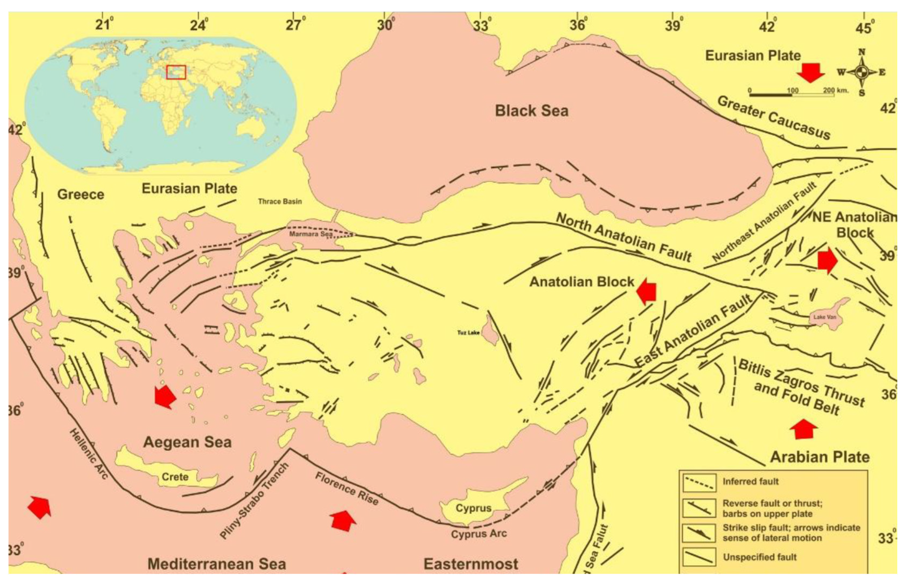
2.1. 6 February 2023 Kahramanmaraş Earthquakes and the East Anatolian Fault System

The North Anatolian Fault System (NAFS) and the East Anatolian Fault System (EAFS) are the two primary fault systems in Türkiye that present significant earthquake hazards. The EAFS acts as a NE-SW left-lateral strike-slip transform boundary between the northward-moving Arabian Plate and the westward-moving Anatolian Block, stretching approximately 580 km in length and averaging 30 km in width [84,85]. It is one of the most active fault systems in Türkiye and plays a crucial role in accommodating the westward movement of the Anatolian Block alongside the NAFS. Current GPS data indicate a slip rate of about 11 ± 2 mm/year.
The EAFS begins at the Karlıova junction in the northeast and extends as a continuous zone to the west of Çelikhan. Here, the southern branch of the fault splits into two, continuing from the Gölbaşı Basin and Pazarcık northward to the Türkoğlu junction in the southwest. It then borders the Amik Plain from the west and terminates by dispersing south of Kırıkhan. In this area, the eastern boundary is formed by the Sakçagöz and Narlı segments of the Dead Sea Fault Zone. The Narlı segment extends from north of Pazarcık towards the EAF for about 30–40 km in an NNE direction. The northern branch, which di-verges west of Çelikhan, curves northward, following the terrain of the Southeastern Taurus Mountain Belt. This branch includes the Sürgü Fault, Çardak Fault, and the Savrun, Çokak, and Toprakkale faults, turning southwest from Göksun (Figure 1).
From 1900 to 6 February 2023, 224 earthquakes (M ≥ 4.0), the largest of which was 6.8, occurred in the region. There are 75 historical earthquake records for the period before 1900. The Eastern Anatolian Fault System experienced a seismically active period, especially in the 19th century. An earthquake series occurred, starting with the Palu earthquake (1789), continuing with the earthquakes of 1822, 1866, 1872, 1874, 1875, and 1893, and finally ending with the Malatya earthquake of 1905 at the beginning of the last century. Although it seems to have entered a relatively calm period after this earthquake until today, the 22 May 1971, Bingöl (6.8 = Ms), 5 May 1986 (5.8 = Ms), and 6 May 1986 (5.6 = Ms) Doğanşehir earthquakes are medium-sized earthquakes produced by the EAFS in the last century. A total of 13 earthquakes (Ms > 5.0) that caused damage to the EAFS occurred in the 20th century. The epicentral distributions of these earthquakes tend to concentrate at the boundaries of the segments.
On 6 February 2023, two earthquakes with magnitudes of Mw = 7.7 and Mw = 7.6 occurred in southeastern Türkiye, with epicenters in Pazarcık (Kahramanmaraş) at 01:17:32 (UTC) and Elbistan (Kahramanmaraş) at 10:24:47 (UTC). The 7.7 magnitude earthquake occurred at a depth of 8.6 km, while the 7.6 magnitude earthquake occurred at a depth of 7 km. Immediately after the first main shock, a large aftershock with a magnitude of Mw = 6.6 occurred at 01:28:16 (UTC). On the same day, the fourth aftershock with a magnitude of Mw = 5.9 occurred at 12:02:11 (UTC). While the aftershock activity of the earthquakes continued, another earthquake with a magnitude of 6.4 Mw occurred in Yayladağı (Hatay) on 20 February 2023. The main shocks and aftershocks occurred within a detection radius of approximately 300 km. These shallow and strong earthquakes were felt very strongly in Kahramanmaraş, Hatay, Adıyaman, Gaziantep, Malatya, Kilis, Diyarbakır, Adana, Osmaniye, Şanlıurfa, and Elazığ, causing more than 50,000 deaths, more than 100,000 injuries and an estimated 500,000 homes becoming uninhabitable. There have been approximately 50,000 aftershocks to date.

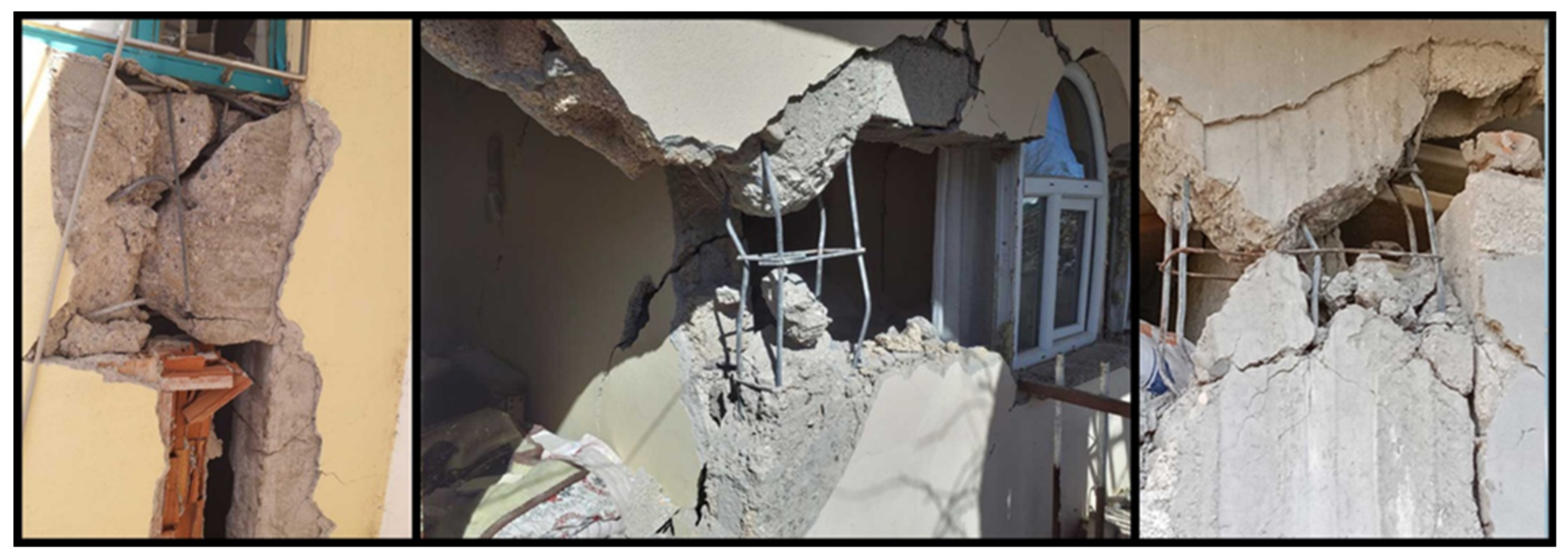
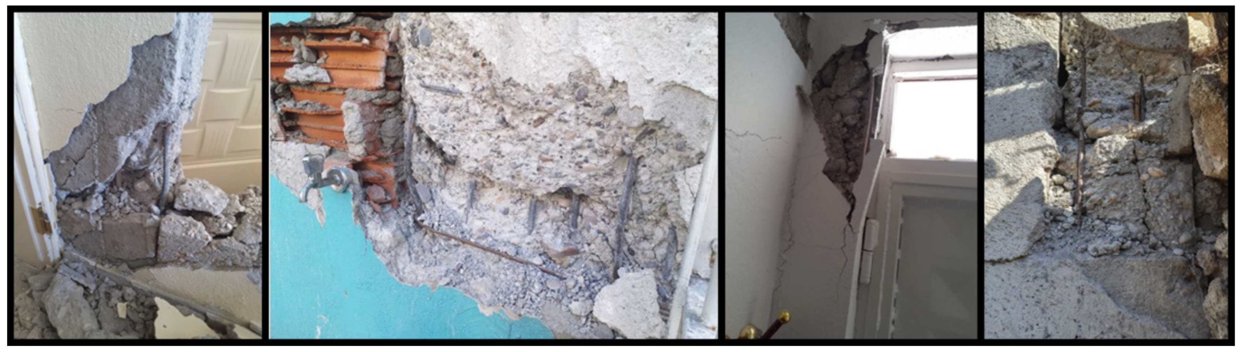
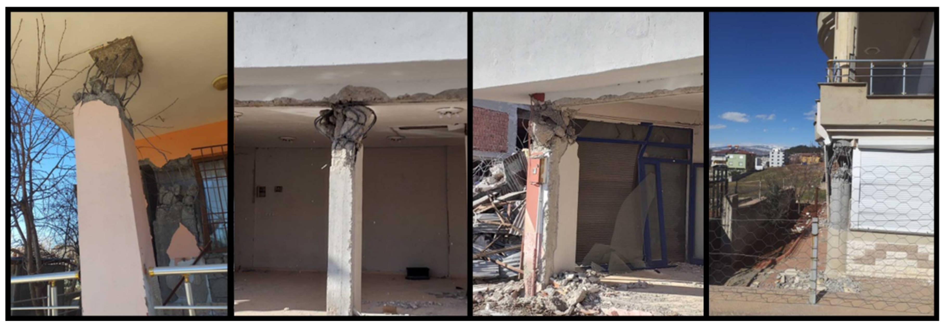
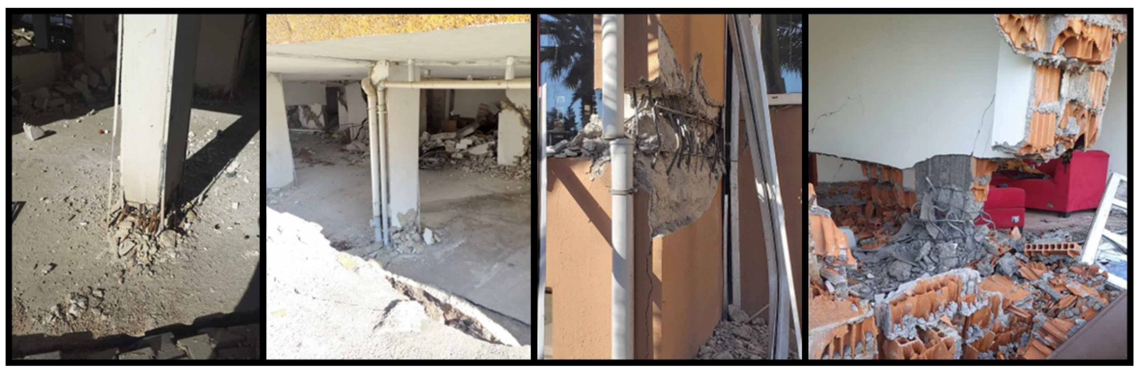
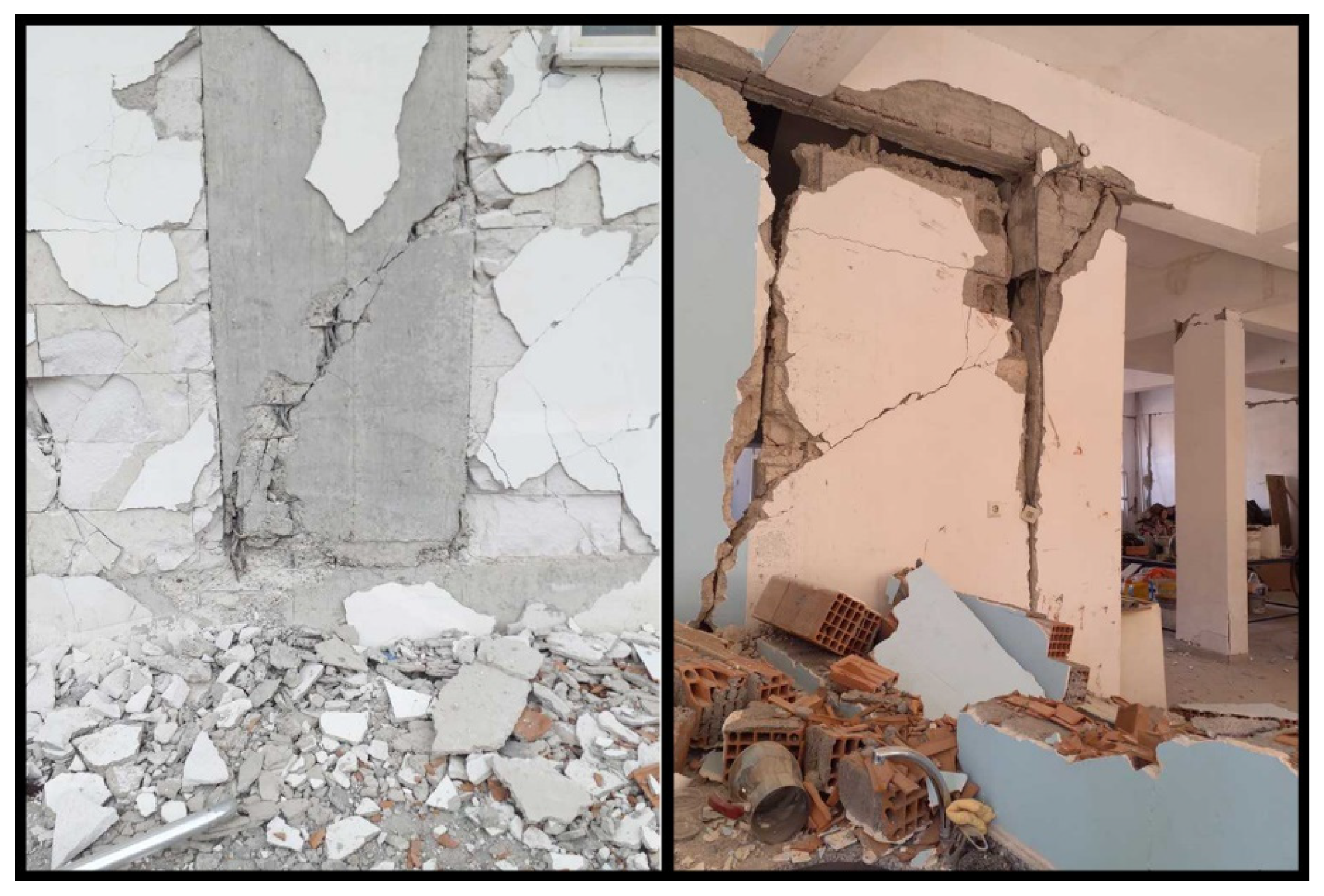
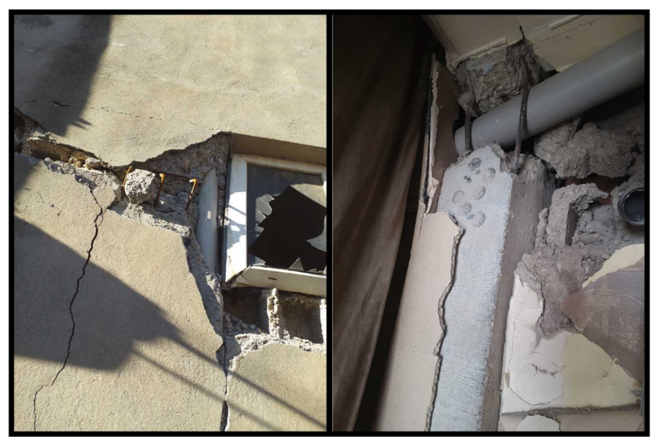
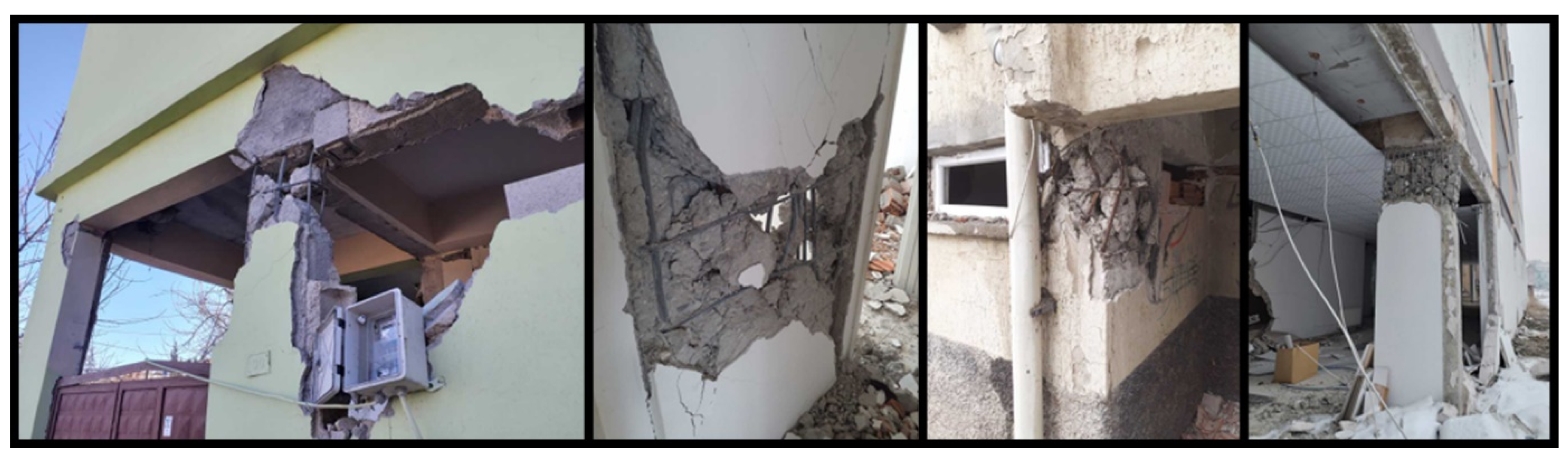
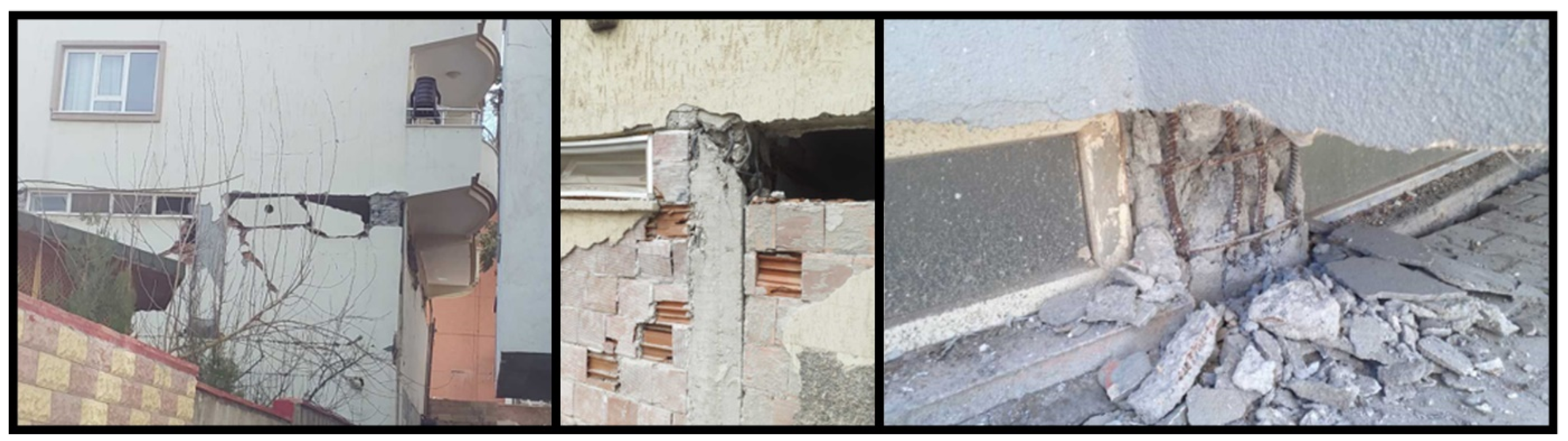
2.2. Structural Damages in RC Columns

Investigations conducted after the earthquakes revealed that buildings with different structural systems experienced collapse and varying levels of damage. In reinforced concrete columns, particularly insufficient transverse reinforcement spacing led to different degrees of damage. The transverse reinforcement used in reinforced concrete structures can wrap around the core concrete, reducing the brittle nature of the concrete. This, in turn, enhances the strength of the concrete and increases the ductility capacity of the element. Additionally, one of the expected functions of transverse reinforcement is to help resist shear forces alongside the concrete, reduce the buckling length of longitudinal reinforcement to prevent potential buckling, and keep the longitudinal reinforcement in place during concrete placement. The use of inadequate transverse reinforcement negatively affects many of these expected functions. Examples of damage caused by insufficient transverse reinforcement are shown in Figure 2.
The low strength of the concrete used in reinforced concrete columns has led to varying levels of structural damage. This low concrete strength is generally due to factors such as the use of non-graded aggregates, insufficient dosage, inadequate mixing, lack of compaction, and insufficient curing. Examples of damage caused by low-strength concrete are shown in Figure 3.
Due to the shear forces acting on reinforced concrete structures, the lateral displacement of the columns on the ground floor can lead to a collapse mechanism in the structural system. As shown in Figure 4, lateral displacement caused by shear forces can be observed in the lower columns.
One of the common types of damage observed in reinforced concrete columns is buckling damage, which occurs in cases where the stirrups are sparse at the ends of the columns. This is because the buckling of the reinforcement can lead to the disintegration of the upper part of the column and shortening under axial load. The resulting changes in the dimensions of the column lead to a different redistribution of forces. For this reason, transverse reinforcement is tightened in the end regions of the columns. In areas where plastic hinges may form, the tightening of the stirrups increases the ductility and strength of the column. The transverse reinforcements used in the design of reinforced concrete elements help shorten the buckling lengths of the longitudinal reinforcements. Examples of plastic hinging that occur at the upper ends of columns due to insufficient transverse reinforcement are shown in Figure 5.
Plastic hinges have also been observed in the lower-end regions of the columns for the same reasons as in the upper regions. Examples of this type of damage in the lower-end regions are shown in Figure 6.
One of the factors affecting the load-bearing capacity of columns is inadequate concrete cover thickness. Insufficient concrete cover over time leads to the corrosion of the reinforcement and a reduction in the reinforcement area, resulting in a decreased load-bearing capacity. Examples of columns that have been damaged due to corrosion from insufficient concrete cover thickness are shown in Figure 7.
Tensile cracks in columns form at an angle to the beam axis. If the shear reinforcement is insufficient, the width of the cracks will be larger. Shear cracks and the subsequent shear failure are undesirable conditions, as they represent a brittle type of failure; examples of a shear crack are shown in Figure 8. If the shear capacity of the columns is inadequate—meaning that sufficient stirrup tightening and details such as the lengths of the reinforcement laps have not been properly addressed—such damage has been observed. In this case, inclined shear cracks at approximately 45° occur in the column, as shown in Figure 8. If there is insufficient stirrup reinforcement in the columns, inclined shear cracks can lead to brittle failure.
For transverse reinforcements to work effectively during an earthquake, it is recommended that the hook lengths are sufficient and the hook angles are bent at 135°. However, in practice, bending them at 90° causes the transverse reinforcements to not anchor sufficiently to the longitudinal reinforcements, resulting in easier slippage of the transverse reinforcements from the longitudinal ones. Examples of this type of damage are shown in Figure 9.
Different installation components passing through the structural system reduce the concrete cross-sectional area. As a result, this can lead to a decrease in the load-bearing capacity of the element. Examples of various installation components passing through a column are shown in Figure 10.
The spalling of core concrete in reinforced concrete columns is generally considered a significant issue affecting the durability of the structure. The spalling of core concrete can result from improper mix ratios, insufficient compaction, excessive loads, chemical effects, and similar factors. Additionally, inadequate transverse reinforcement used to reduce the brittle characteristics of the core concrete can also contribute to this condition. Examples of this type of damage are shown in Figure 11.
Reinforcement workmanship is a significant factor in the performance of the expected functions of the reinforcements in reinforced concrete columns. Due to the altered position and arrangement of the reinforcements, the load-bearing capacities of the structural elements can be exceeded, leading to damage. Examples of damage resulting from poor reinforcement workmanship are illustrated in Figure 12.
In RC columns, having ribbed longitudinal reinforcements and plain transverse reinforcements negatively affects the combined behavior of these reinforcements under loads, leading to inadequate anchorage and adversely impacting the expected functions of the reinforcements. Examples of damage observed in columns with ribbed longitudinal reinforcements and plain transverse reinforcements are shown in Figure 13.
Short column-induced damage is among the frequently observed structural failures following earthquakes. Variations in column heights within a structure can occur due to several factors. In this case, although a reduction in column height enhances structural stiffness, it concurrently decreases the moment arm length. Short columns, due to their limited height relative to other dimensions, experience reduced lateral displacement under horizontal loads. This can lead to increased shear forces, causing structural damage at different levels. Examples of damage in short columns are presented in Figure 14.
Another reason for the damage in columns is the additional shear forces created in the columns of neighboring buildings due to the pounding effect during an earthquake, especially in buildings constructed in a combined arrangement. This additional shear force can exceed the expected shear force for the load-bearing element, leading to damage. Examples of damage in the columns of neighboring structures resulting from the pounding effect are shown in Figure 15.
The requirements for transverse reinforcement in RC columns, as specified in the last two seismic design codes used in Türkiye, are illustrated in Figure 16.
Post-earthquake field investigations indicated that the transverse reinforcement spacing in both the confinement (core) and central regions of the columns exceeded the code-specified limits. In several RC columns, transverse reinforcement was entirely absent. Moreover, special seismic ties required by TBEC-2018 were found to be completely omitted. Additionally, transverse reinforcements were anchored to the longitudinal bars at 90°, rather than the prescribed 135°, compromising their confinement effectiveness. Insufficient concrete cover further contributed to reinforcement corrosion and a reduction in bond strength. These combined deficiencies hindered the composite action of transverse and longitudinal reinforcements during seismic loading, resulting in their separation.
In Türkiye, the concrete classes prescribed in the 1975, 1998, 2007, and 2018 earthquake codes are C14, C16, C20, and C25, respectively. It has been stated in many studies that post-earthquake concrete strengths are lower than predicted during the 2023 Kahramanmaraş earthquakes [88,89,90,91,92]. The primary factors contributing to concrete damage during the earthquake were related both to material properties and to design and construction deficiencies. The compressive strength of the concrete may have been inadequate due to the use of low-quality materials or improper mix proportions. Inadequate compaction (lack of vibration), inappropriate aggregate gradation, and poor workmanship played a critical role in the crushing, cracking, and disintegration of concrete. Within the scope of this study, it was attempted to reveal the effects of these two parameters on RC columns.

3. Results

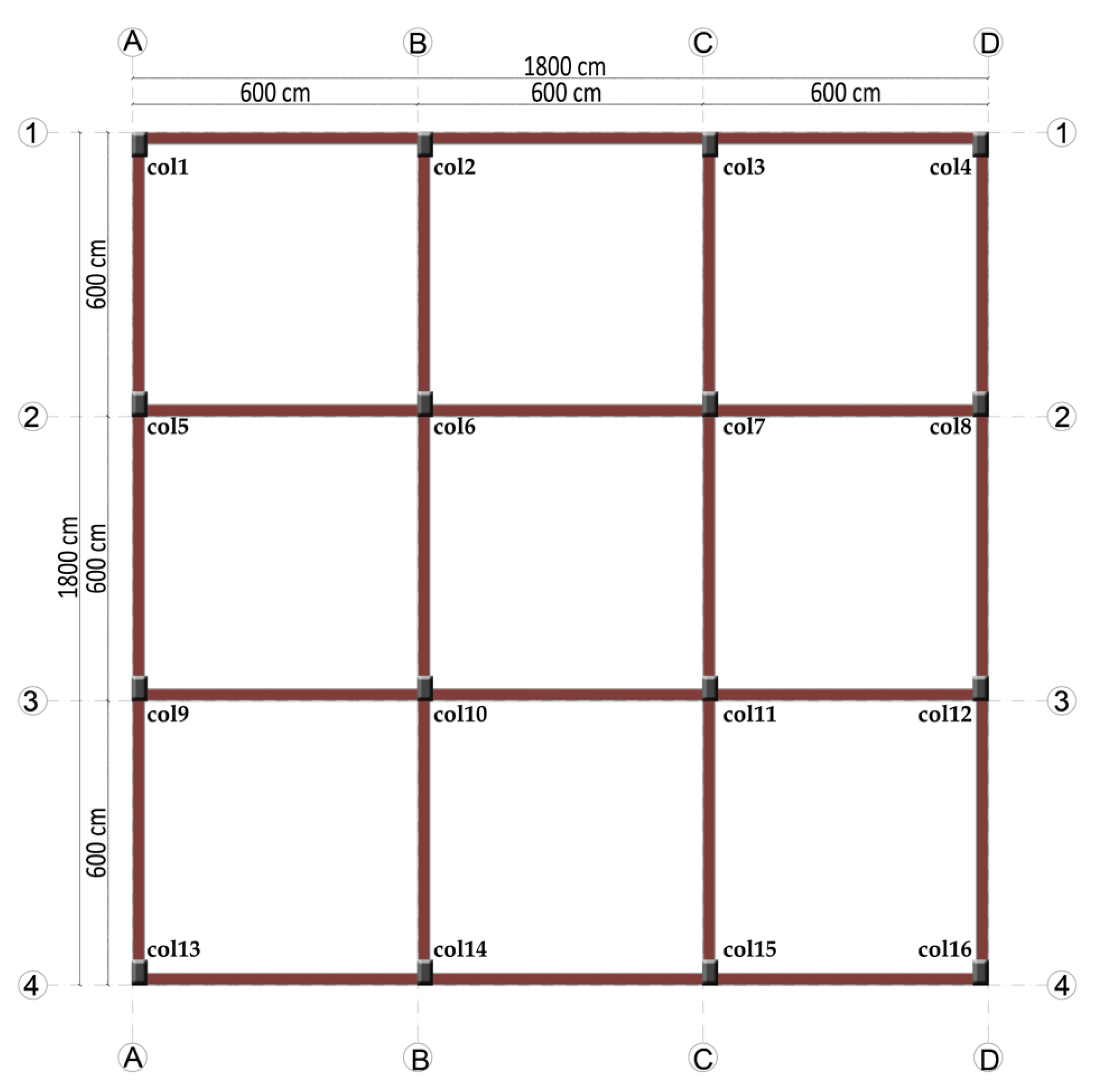
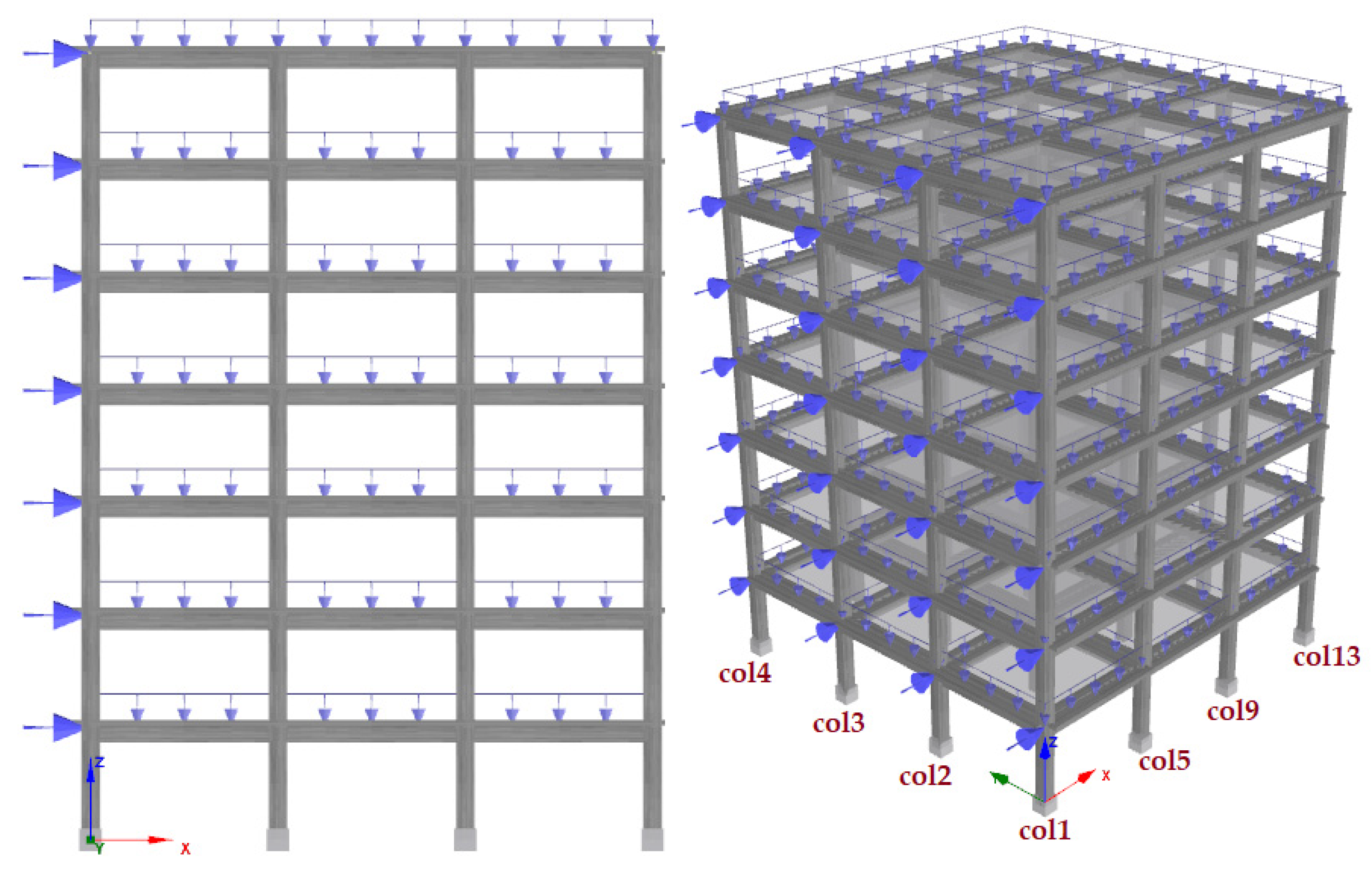
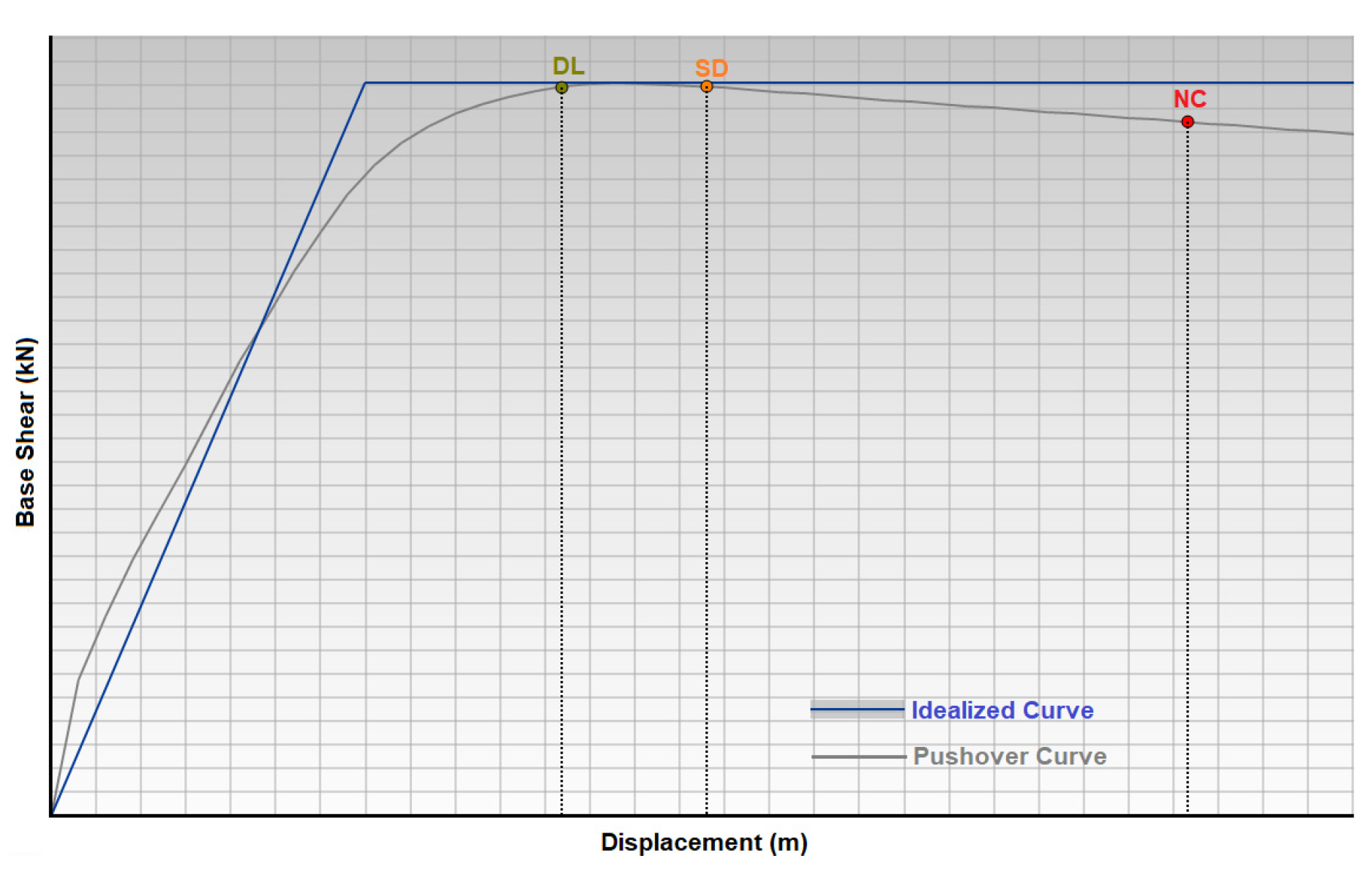
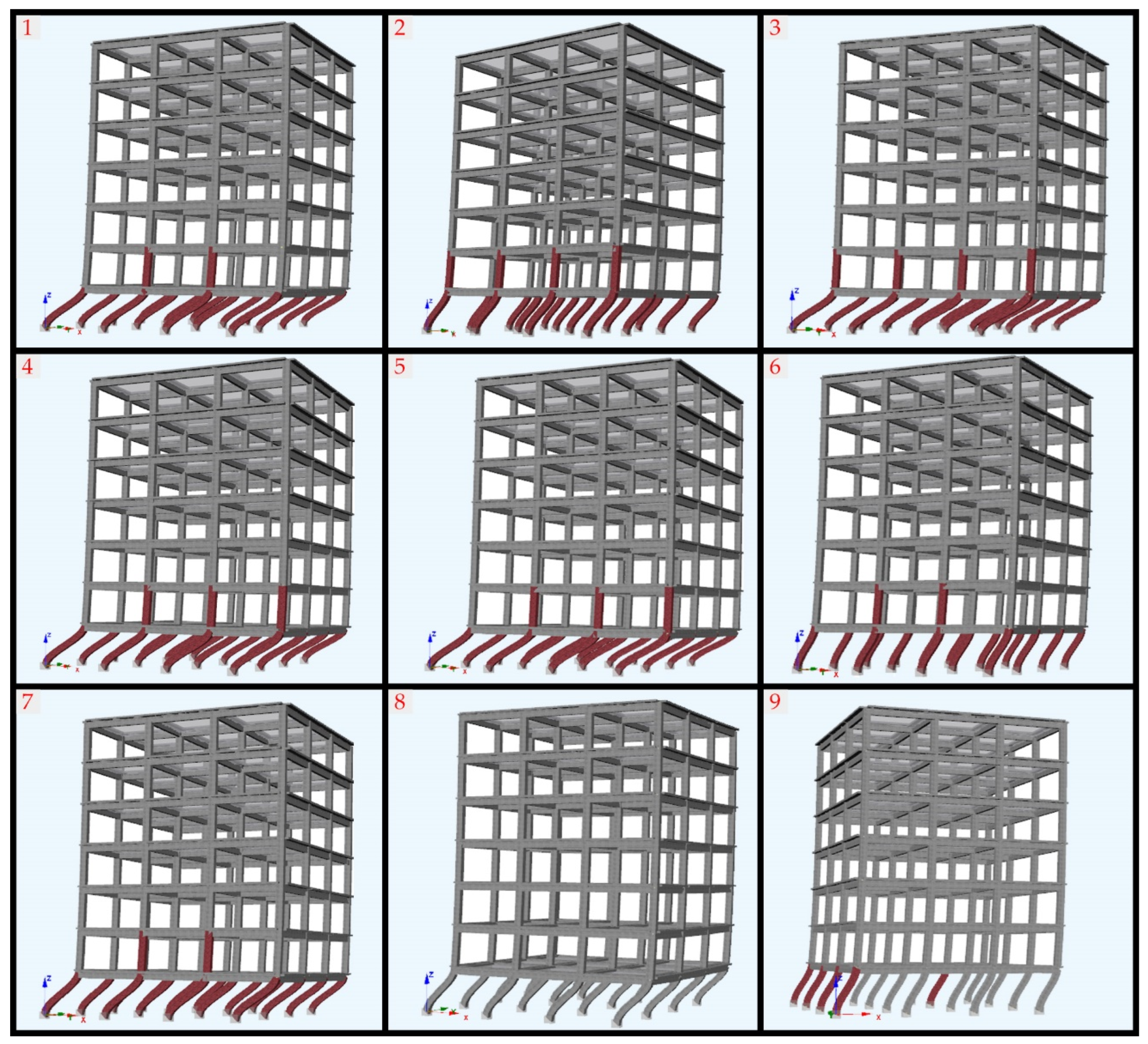
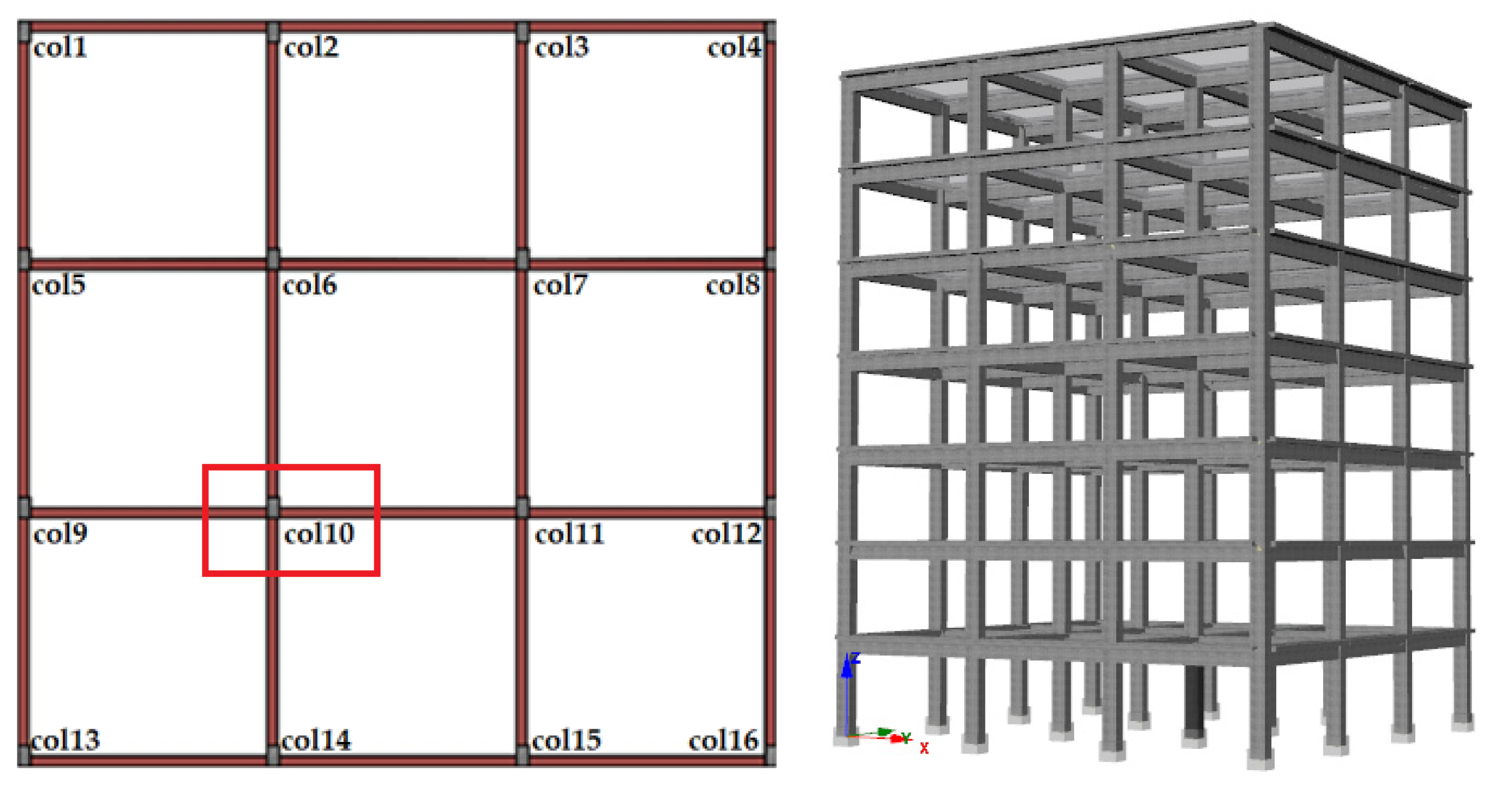
3.1. Numerical Analysis

In RC structures, structural analyses were conducted by varying key factors affecting the inadequate shear capacity in columns, such as concrete strength and the spacing of transverse reinforcement. SeismoStruct-2024 [93] software was used for the numerical analyses. Pushover analysis was employed in these numerical analyses. Structural nonlinear behavior due to earthquakes can be assessed using either nonlinear time history analysis or static pushover analysis. The pushover analysis method determines structural nonlinear responses through a series of linear operations, enabling the development of a structural capacity curve. This approach effectively tracks the damage states of a structure at each step, illustrating how deterioration progresses from minor damage to complete failure.
In modelling all structural samples, force-based plastic hinge frame elements (infrmFBPH) were utilized for both columns and beams. These elements model the spread of inelastic behavior based on force, limiting plasticity to a finite length. The ideal number of fibers in the cross-section should be adequate to accurately represent the stress–strain distribution [94]. A total of 100 fiber elements were defined for the chosen sections, which is sufficient for this type of modeling. The length of the plastic hinge (Lp/L) was determined to be 16.67%, based on structural analysis and design guidelines. This value represents the proportion of the column or beam length where plastic deformations are expected to occur under loading conditions, ensuring that the structure can dissipate energy efficiently while maintaining stability. The selection of this ratio is consistent with common engineering practice for determining the plastic hinge length in structural components subject to inelastic behavior.
The selected RC structure model has three spans in each direction, with each span chosen to be 6 m. The floor plan of the RC structure model and the representation of the columns are shown in Figure 17.
The 2D and 3D visuals of the constructed building model are shown in Figure 18.
The structural characteristics that remain constant in the models used for numerical analyses are shown in the Table 1.
The cross-sections of the columns considered in the numerical analyses before and after reinforcement are shown in Figure 19.
In this study, structural models were created by considering two key variables that affect the shear capacity of columns. The constructed structural models and their details are provided in Table 2. The variables were selected based on the causes of damage observed in the columns, particularly following the Kahramanmaraş earthquakes and subsequent field investigations conducted by the authors. Another reason for this selection is to provide a foundational basis for the strengthening that will be carried out using FRP in the subsequent sections of the study.
Pushover analysis was used in all structural models. Pushover analysis, a numerical technique, investigates the extent of deformation and the behavior of structures or structural elements under a specific load. This type of analysis typically considers both elastic and plastic responses. Pushover analysis is widely employed in earthquake engineering to predict how a structure will respond during seismic events. The method evaluates the deformation of a structure subjected to static loads (usually simulating ground motion) and identifies the point at which damage may occur. It is less complex and faster to perform than more advanced dynamic analyses. This approach enables the assessment of displacement, rotation, and potential damage locations within the structure [94,95,96,97]. Uniform load distributions were taken into account in all structural analyses. For the models considered in this study, the period, base shear force, as well as the elastic and effective stiffness values, were first obtained. Additionally, the target displacements specified in Eurocode-8 [98] which are commonly used worldwide, namely damage limitation (DL), significant damage (SD), and near collapse (NC), were separately determined. The target displacements taken into consideration are shown in Figure 20. All target displacements for structural models are presented in the Table 3.
Concrete strength directly influences the seismic behavior of RC structures. As the concrete strength increases, the structure becomes more rigid, and the period value decreases. As a result, the seismic capacity of the structure improves. Additionally, an increase in concrete class has only slightly affected the target displacements. As the strength of concrete diminishes, there is a slight increase in the anticipated target displacements of the structure. This is because lower concrete strength leads to a reduction in the overall stiffness and load-carrying capacity of structural elements. Consequently, the structure exhibits greater deformations under the same level of applied loading. Additionally, lower-strength concrete tends to undergo more pronounced inelastic behavior, contributing to increased displacements even before reaching critical damage states. Although the change in displacement may be moderate, it reflects the sensitivity of the global structural response to variations in material properties. The spacing of transverse reinforcements does not have significant effects on these parameters, as they are not among the expected functions of transverse reinforcements. One of the main functions expected from transverse reinforcements is their effect on shear force, which constitutes the primary objective of this study. Shear force limit values are determined according to user-defined material, section, and modeling parameters and are generally evaluated within the scope of plastic hinge definitions and shear damage criteria. In the scope of this study, these values were obtained by taking into account the more widely used Eurocode. The comparison of demand and limit shear forces is presented in Table 4. The comparison was conducted for columns that exceeded the limit state.
According to the results of the static pushover analyses, the number of columns exceeding the limit state and their ratio to the total number of columns in the structure are presented in Table 5.
With the increase in the spacing of transverse reinforcements, the number of columns exceeding the shear force limit has increased. However, with the increase in concrete strength, there is a significant reduction in the number of columns with shear force exceedance. Both the spacing of transverse reinforcements and concrete strength significantly affect the performance of columns under shear force. Additionally, factors such as reinforcement layout, concrete cover thickness, reinforcement workmanship, and reinforcement quality will directly impact the damage that may occur under shear force effects in these elements. Insufficient spacing of transverse reinforcements can lead to buckling of longitudinal reinforcements and brittle behavior of the core concrete. As a result of structural analyses and field investigations, it is essential that transverse reinforcements be applied with precision as specified in earthquake regulations.
The shear force deformation states obtained for all models considered in the study and the representation of columns exceeding the shear force limit are shown in Figure 21.
As seen in Figure 18, when the concrete strength is C30/37, there are no column elements that exceed the shear force limit. This indicates that concrete strength directly affects shear force capacity, and as the concrete strength increases, the number of columns exceeding the shear force limit decreases.

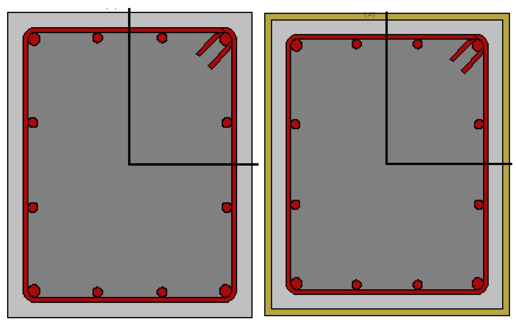
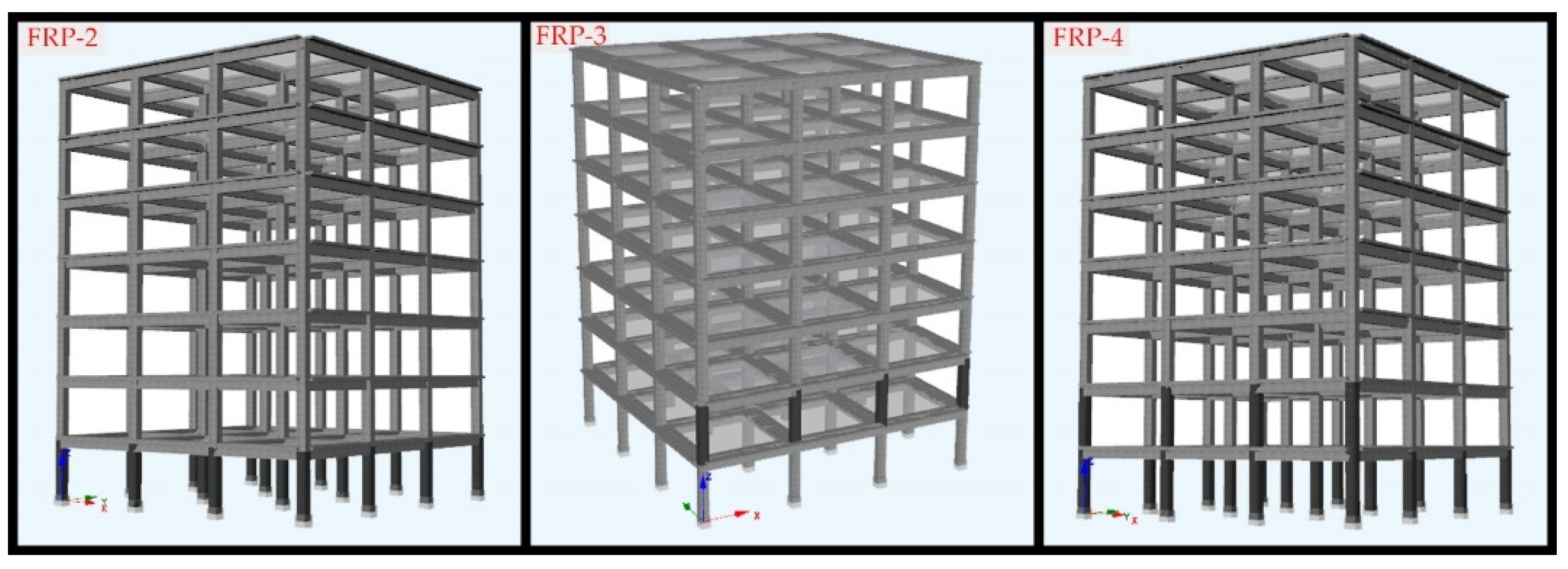
3.2. Strengthening Columns with FRP

One of the main objectives of strengthening buildings is to enhance the seismic safety of structures that do not perform adequately during earthquakes and to address defects that may cause earthquake damage. Additionally, improving the seismic behavior of existing structural elements is another applicable strengthening method. In columns, the use of fiber-reinforced polymers through wrapping enhances the ductility capacity, shear strength, and compressive strength of reinforced concrete columns, especially in cases where the longitudinal reinforcement lap length is inadequate (TBEC-2018, [87]). However, such strengthening procedures do not increase the flexural capacity of the columns. FRP wrapping reinforcement generally increases the axial carrying capacity and ductility of the column, but does not contribute significantly to the flexural capacity when applied in transverse wrapping. Because FRP wrapping does not increase the moment-carrying longitudinal reinforcement, its main effect is to delay the buckling of the concrete and improve the section ductility and energy dissipation capacity. Strengthening reinforced concrete columns with carbon fiber is an effective method to enhance the load-bearing capacity and durability of the structure. Carbon fiber reinforcement increases the capacity of structural elements due to its lightweight and high tensile strength, without significantly adding to the weight of the structure. The properties of the FRP-strengthening materials considered in this study are shown in Table 6. In all analyses, FRP was applied as a single-layer wrapping. The corner radius of the fibers was assumed to be 40 mm, and no additional anchorage was considered at the corner regions.
In this study, the strengthening with FRP was performed on Model 3, which had the lowest concrete strength and the maximum spacing of transverse reinforcement, as part of the structural analyses. Initially, the FRP strengthening method was evaluated using a single column. For this purpose, col10 located on the first floor was selected as an example (FRP-1). The representation of the selected column on the floor plan and its 3D model are shown in Figure 22.
To evaluate the FRP strengthening more comprehensively, three additional FRP strengthening models were created, still considering Model 3, which has the worst conditions. The structural models resulting from the FRP strengthening applied to each of the three models are shown in Figure 23. In the FRP-2 model, FRP was applied to all columns on the ground storey where the shear force limit was exceeded for Model 3. In the FRP-3 model, FRP was applied only to the columns on the second storey that exceeded the shear force limit values. In the FRP-4 model, FRP was applied to all columns where the shear force capacity was exceeded on both the first and second stories (Figure 24).
In the FRP-1 model, all columns, except the strengthened column (Col10), exceeded the limit shear force. In the FRP-2 model, as all columns on the ground floor were strengthened, they all satisfied the limit shear force requirement. Conversely, on the un-strengthened second floor, the majority of the columns surpassed the limit value. In the FRP-3 model, where only the second floor was strengthened, the columns on this floor did not exceed the limit value. However, all un-strengthened columns on the ground floor exceeded the limit value. In the FRP-4 model, the strengthening of columns on both floors ensured that all columns satisfied the limit shear force criterion. It is clearly seen that the FRPs used in the models provide a significant contribution to increasing the shear force in the columns at different positions, thus eliminating capacity overshoot. In this way, reinforcements can be used in damaged reinforced concrete buildings as well as in increasing the strength of existing structures with inadequate earthquake performance. Considering all structural models that are strengthened, it reveals the applicability of such processes in element-based strengthening processes, especially in increasing the shear force capacity.
The comparison of demand and limit shear forces for the structural models strengthened with FRP is presented in Table 7.

4. Conclusions and Discussion

The main objective of this study is to investigate the structural failures in reinforced concrete columns observed during the 2023 Kahramanmaraş earthquakes, which caused unprecedented damage in a wide area of Türkiye. The column damages observed as a result of field observations were taken into account. In this context, the two main causes of the damages, such as low-strength concrete and insufficient transverse reinforcement, were determined, and the focus was on revealing their effects in numerical analyses. The limitation regarding the year in which the investigated structures were constructed according to the seismic design codes is due to the lack of consistent availability of comprehensive data regarding construction dates and code compliance for the damaged buildings during the field investigations. As a result, instead of trying to generalize based on incomplete historical records, it was chosen to focus on the structural performance patterns observed in a series of typical concrete strength and reinforcement details. We believe that the study still contributes significantly by modeling various structural scenarios reflecting widespread weaknesses in Türkiye’s reinforced concrete building stock and demonstrating the effectiveness of FRP strengthening strategies under the worst conditions. Consolidating RC elements using FRP aligns with sustainable development goals by improving structural integrity, reducing environmental impacts, and promoting efficient resource usage. This technique not only meets current engineering needs but also supports a shift towards more sustainable construction practices.
In RC structures, the seismic performance of the columns, which are the primary load-bearing elements, directly affects the overall seismic performance of the building. Properly designed and executed columns will allow the structure to dissipate sufficient energy during an earthquake. The correct detailing of concrete and reinforcement in columns, constructed according to earthquake-resistant design principles, ensures the safe transfer of loads. The 2023 Kahramanmaraş earthquakes once again highlighted that low-strength concrete and poor reinforcement properties were significant factors in column damage. Field observations revealed that column damage was prominent and played a critical role in structural damage. Based on field observations and structural analyses, the key parameters affecting the performance of transverse reinforcements are listed below:
  • Transverse reinforcement diameter;
  • Transverse reinforcement spacing;
  • The use of different types of reinforcement together;
  • Preference for plain reinforcement;
  • Low-strength concrete;
  • Corrosion;
  • Bend angle of transverse reinforcements;
  • Poor reinforcement workmanship;
  • Insufficient concrete cover thickness;
  • Inadequate anchorage between transverse and longitudinal reinforcements;
  • Short column effect;
  • Impact effect;
  • Lack of special seismic stirrups (ties) usage.
Field observations indicate that the primary causes of damage in columns are low-strength concrete and insufficient transverse reinforcement. Transverse reinforcements (stirrups) are used to increase the shear strength of RC columns. Additionally, transverse reinforcements create a confining effect in the concrete, enhancing both its strength and ductility, while also shortening the buckling lengths of the longitudinal reinforcements. In this study, both of these negative factors—low-strength concrete and inadequate transverse reinforcement—were selected as variables for analysis. It has been clearly demonstrated that both variables significantly affect the limit and demand values of shear forces in columns.
The effect of transverse reinforcement spacing is critically important for the safety and durability of structures. Adequate spacing of transverse reinforcements enhances the shear and cracking resistance of the core concrete, positively influencing load-bearing capacity. Furthermore, proper placement of transverse reinforcements improves the workability and durability of concrete, extending the lifespan of the structure. However, excessive spacing of transverse reinforcements can increase the risk of cracking in the concrete, jeopardizing the integrity of the structure. Consequently, determining appropriate transverse reinforcement spacing is a critical design factor in structural engineering and plays a significant role in constructing safe and durable structures.
The impact of low-strength concrete on the seismic behavior of columns can seriously affect a structure’s performance during an earthquake. Low-strength concrete is more prone to inelastic deformations and cracking, which can reduce the load-carrying capacity of columns under seismic loads. This situation endangers the stability of the structure, leading to both material damage and loss of structural integrity. Additionally, the use of low-strength concrete can negatively affect energy distribution, increasing potential damage during an earthquake. Therefore, using high-strength concrete in seismic design is crucial for enhancing the safety of the structure and minimizing potential earthquake damage.
The post-earthquake assessments highlight the critical importance of code compliance, construction supervision, and the need to retrofit older buildings that do not meet current seismic design codes. The study also reveals that the FRP strengthening method significantly increases the shear capacity of columns. This method can be rapidly and practically applied to existing reinforced concrete structures, which constitute a large portion of the urban building stock and suffer from shear capacity.
FRP materials can make significant contributions to sustainability in the construction industry. They reduce both material consumption and environmental impacts by making structures lighter, more durable, and more energy efficient. However, developing recycling processes for FRP materials and making their production stages more environmentally friendly will increase the sustainability of these materials. In other words, FRP reinforcement can offer a sustainable construction solution when combined with the right technologies.
Comparing with the traditional solutions for retrofitting and consolidation, FRP presents a sustainable and effective solution for addressing failures in RC columns. Its unique properties not only enhance strength and durability but also significantly improve the resilience of structures against corrosion, seismic events, and overload conditions. As research and technology surrounding FRP continue to advance, its adoption in construction and remediation practices is likely to increase, contributing to more sustainable and robust structures.
This and similar studies can be used to compare different FRP types, analyze behavior under high axial load, develop numerical modeling methods for multi-layer or hybrid reinforcement techniques, and carry out similar reinforcement studies on RC beams.
Due to the increase in awareness and quality control mechanisms following the 1999 Marmara (Türkiye) earthquakes and the enactment of the new seismic design code in 1998, which included ductile design principles, there was more destruction in buildings before 2000, which was an important turning point. However, many new buildings constructed in the following years were also damaged. All these factors, despite the measures in quality control mechanisms and updated regulations, cause widespread errors in construction practices to emerge and bring to the agenda the precautions that need to be taken.

Author Contributions

Conceptualization, E.I. and F.A.; methodology, E.I. and F.A.; software, A.B.; validation, E.H., E.A. and D.R.; formal analysis, M.H.-N.; investigation, E.A.; writing—original draft preparation, E.I., D.R. and M.H.-N.; writing—review and editing, E.I. and D.R.; visualization, E.I.; supervision, F.A. All authors have read and agreed to the published version of the manuscript.

Funding

This research received no external funding.

Data Availability Statement

The raw data supporting the conclusions of this article will be made available by the authors on request.

Acknowledgments

The results presented in this scientific paper have been partially obtained through the research activities within the project 2023-1-HR01-KA220-HED-000165929 Intelligent Methods for Structures, Elements and Materials (https://im4stem.eu/en/home/, accessed on 4 June 2024) co-funded by the European Union under the program Erasmus+ KA220-HED—Cooperation partnerships in higher education.

Conflicts of Interest

The authors declare no conflicts of interest.

References

  1. Papatheodorou, K.; Theodoulidis, N.; Klimis, N.; Zulfikar, C.; Vintila, D.; Cardanet, V.; Kirtas, E.; Toma-Danila, D.; Margaris, B.; Fahjan, Y.; et al. Rapid earthquake damage assessment and education to improve earthquake response efficiency and community resilience. Sustainability 2023, 15, 16603. [Google Scholar] [CrossRef]
  2. Shafapourtehrany, M.; Batur, M.; Shabani, F.; Pradhan, B.; Kalantar, B.; Özener, H. A comprehensive review of geospatial technology applications in earthquake preparedness, emergency management, and damage assessment. Remote Sens. 2023, 15, 1939. [Google Scholar] [CrossRef]
  3. Crowley, H.; Despotaki, V.; Silva, V.; Dabbeek, J.; Romão, X.; Pereira, N.; Castro, J.M.; Daniell, J.; Veliu, E.; Bilgin, H.; et al. Model of seismic design lateral force levels for the existing reinforced concrete European building stock. Bull. Earthq. Eng. 2021, 19, 2839–2865. [Google Scholar] [CrossRef]
  4. Ademović, N.; Toholj, M.; Radonić, D.; Casarin, F.; Komesar, S.; Ugarković, K. Post-earthquake assessment and strengthening of a cultural-heritage residential masonry building after the 2020 Zagreb earthquake. Buildings 2022, 12, 2024. [Google Scholar] [CrossRef]
  5. Alpyürür, M.; Ulutaş, H. Comparison of performance analysis results with developed site-specific response spectra and Turkish seismic design code: A case study from the SW Türkiye region. Buildings 2024, 14, 1233. [Google Scholar] [CrossRef]
  6. Duvnjak, I.; Ereiz, S.; Smrkić, M.F.; Damjanović, D. Post-Earthquake dynamic performance of intact masonry building based on finite element model updating. Appl. Sci. 2023, 13, 9042. [Google Scholar] [CrossRef]
  7. Valente, M. Seismic performance assessment of a non-ductile RC building retrofitted by steel bracing or fiber-reinforced polymers. Appl. Mech. Mater. 2012, 234, 84–89. [Google Scholar] [CrossRef]
  8. Işık, M.F.; Işık, E.; Bülbül, M.A. Application of iOS/Android based assessment and monitoring system for building inventory under seismic impact. Gradjevinar 2018, 70, 1043–1056. [Google Scholar] [CrossRef]
  9. Valente, M. Earthquake response and damage patterns assessment of two historical masonry churches with bell tower. Eng. Fail. Anal. 2023, 151, 107418. [Google Scholar] [CrossRef]
  10. Işık, E.; Avcil, F.; İzol, R.; Büyüksaraç, A.; Bilgin, H.; Harirchian, E.; Arkan, E. Field reconnaissance and earthquake vulnerability of the RC Buildings in Adıyaman during 2023 Türkiye earthquakes. Appl. Sci. 2024, 14, 2860. [Google Scholar] [CrossRef]
  11. İnce, O. Structural damage assessment of reinforced concrete buildings in Adıyaman after Kahramanmaraş (Türkiye) Earthquakes on 6 February 2023. Eng. Fail. Anal. 2024, 156, 107799. [Google Scholar] [CrossRef]
  12. Avğın, S.; Köse, M.M.; Özbek, A. Damage assessment of structural and geotechnical damages in Kahramanmaraş during the February 6, 2023 earthquakes. Eng. Sci. Technol. Int. J. 2024, 57, 101811. [Google Scholar] [CrossRef]
  13. Yön, B.; Dedeoğlu, İ.Ö.; Yetkin, M.; Erkek, H.; Calayır, Y. Evaluation of the seismic response of reinforced concrete buildings in the light of lessons learned from the February 6, 2023, Kahramanmaraş, Türkiye earthquake sequences. Nat. Hazards 2024, 121, 873–909. [Google Scholar] [CrossRef]
  14. Sezgin, S.K.; Sakcalı, G.B.; Özen, S.; Yıldırım, E.; Avcı, E.; Bayhan, B.; Çağlar, N. Reconnaissance report on damage caused by the February 6, 2023, Kahramanmaraş Earthquakes in reinforced-concrete structures. J. Build. Eng. 2024, 89, 109200. [Google Scholar] [CrossRef]
  15. Ivanov, M.L.; Chow, W.K. Structural damage observed in reinforced concrete buildings in Adiyaman during the 2023 Turkiye Kahramanmaras earthquakes. Structures 2023, 58, 105578. [Google Scholar] [CrossRef]
  16. Ozturk, M.; Arslan, M.H.; Korkmaz, H.H. Effect on RC buildings of 6 February 2023 Turkey earthquake doublets and new doctrines for seismic design. Eng. Fail. Anal. 2023, 153, 107521. [Google Scholar] [CrossRef]
  17. Demir, A.; Celebi, E.; Ozturk, H.; Ozcan, Z.; Ozocak, A.; Bol, E.; Sert, S.; Sahin, F.Z.; Arslan, E.; Yaman, Z.D.; et al. Destructive impact of successive high magnitude earthquakes occurred in Türkiye’s Kahramanmaraş on February 6, 2023. Bull. Earthq. Eng. 2024, 23, 893–919. [Google Scholar] [CrossRef]
  18. Binici, B.; Yakut, A.; Kadas, K.; Demirel, O.; Akpinar, U.; Canbolat, A.; Yurtseven, F.; Oztaskin, O.; Aktas, S.; Canbay, E. Performance of RC buildings after Kahramanmaraş earthquakes: Lessons toward performance based design. Earthq. Eng. Eng. Vibr. 2023, 22, 883–894. [Google Scholar] [CrossRef]
  19. Vuran, E.; Serhatoğlu, C.; Timurağaoğlu, M.Ö.; Smyrou, E.; Bal, İ.E.; Livaoğlu, R. Damage observations of RC buildings from 2023 Kahramanmaraş earthquake sequence and discussion on the seismic code regulations. Bull. Earthq. Eng. 2024, 23, 1153–1182. [Google Scholar] [CrossRef]
  20. Mertol, H.C.; Tunç, G.; Akış, T.; Kantekin, Y.; Aydın, İ.C. Investigation of RC buildings after 6 February 2023, Kahramanmaraş, Türkiye earthquakes. Buildings 2023, 13, 1789. [Google Scholar] [CrossRef]
  21. Altunişik, A.C.; Arslan, M.E.; Kahya, V.; Aslan, B.; Sezdirmez, T.; Dok, G.; Kirtel, O.; Öztürk, H.; Sunca, F.; Baltaci, A.; et al. Field observations and damage evaluation in reinforced concrete buildings after the february 6th, 2023, Kahramanmaras-Turkiye earthquakes. J. Earthq. Tsun. 2023, 17, 2350024. [Google Scholar] [CrossRef]
  22. Altunsu, E.; Güneş, O.; Öztürk, S.; Sorosh, S.; Sarı, A.; Beeson, S.T. Investigating the structural damage in Hatay province after Kahramanmaraş-Türkiye earthquake sequences. Eng. Fail. Anal. 2024, 157, 107857. [Google Scholar] [CrossRef]
  23. Yuzbasi, J. Post-Earthquake Damage assessment: Field observations and recent developments with recommendations from the Kahramanmaraş earthquakes in Türkiye on February 6th, 2023 (Pazarcık M7. 8 and Elbistan M7. 6). J. Earthq. Eng. 2024, 1–26. [Google Scholar] [CrossRef]
  24. Cetin, K.O.; Cuceoglu, F.; Ayhan, B.U.; Yildirim, S.; Aydin, S.; Demirdogen, S.; Er, Y.; Gurbuz, A.; Moss, R.E.S. Performance of hydraulic structures during 6 February 2023 Kahramanmaraş, Türkiye, earthquake sequence. Earthq. Spectra 2024, 40, 2231–2267. [Google Scholar] [CrossRef]
  25. Akar, F.; Işık, E.; Avcil, F.; Büyüksaraç, A.; Arkan, E.; İzol, R. Geotechnical and structural damages caused by the 2023 Kahramanmaraş Earthquakes in Gölbaşı (Adıyaman). Appl. Sci. 2024, 14, 2165. [Google Scholar] [CrossRef]
  26. Çelebi, E.; Aktas, M.; Çağlar, N.; Özocak, A.; Kutanis, M.; Mert, N.; Özcan, Z. October 23, 2011, Turkey/Van–Ercis earthquake: Structural damages in the residential buildings. Nat. Hazards 2013, 65, 2287–2310. [Google Scholar] [CrossRef]
  27. Tapan, M.; Comert, M.; Demir, C.; Sayan, Y.; Orakcal, K.; Ilki, A. Failures of structures during the October 23, 2011 Tabanlı (Van) and November 9, 2011 Edremit (Van) earthquakes in Turkey. Eng. Fail. Anal. 2013, 34, 606–628. [Google Scholar] [CrossRef]
  28. Zengin, B.; Aydin, F. The effect of material quality on buildings moderately and heavily damaged by the Kahramanmaraş Earthquakes. Appl. Sci. 2023, 13, 10668. [Google Scholar] [CrossRef]
  29. Yakut, A.; Sucuoğlu, H.; Binici, B.; Canbay, E.; Donmez, C.; İlki, A.; Caner, A.; Celik, O.C.; Ay, B.Ö. Performance of structures in İzmir after the Samos island earthquake. Bull. Earthq. Eng. 2021, 20, 7793–7818. [Google Scholar] [CrossRef]
  30. Doğangün, A.; Ural, A.; Sezen, H.; Güney, Y.; Fırat, F.K. The 2011 earthquake in Simav, Turkey and seismic damage to reinforced concrete buildings. Buildings 2013, 3, 173–190. [Google Scholar] [CrossRef]
  31. Yazgan, U.; Oyguç, R.; Ergüven, M.E.; Celep, Z. Seismic performance of buildings during 2011 Van earthquakes and rebuilding efforts. Earthq. Eng. Eng. Vibr. 2016, 15, 591–606. [Google Scholar] [CrossRef]
  32. Işık, E.; Hadzima-Nyarko, M.; Radu, D.; Bulajić, B. Study on effectiveness of regional risk prioritisation in reinforced concrete structures after earthquakes. Appl. Sci. 2024, 14, 6992. [Google Scholar] [CrossRef]
  33. Erbaş, Y.; Mercimek, Ö.; Anıl, Ö.; Çelik, A.; Akkaya, S.T.; Kocaman, İ.; Gürbüz, M. Design deficiencies, failure modes and recommendations for strengthening in reinforced concrete structures exposed to the February 6, 2023 Kahramanmaraş Earthquakes (Mw 7.7 and Mw 7.6). Nat. Hazards 2025, 121, 3153–3194. [Google Scholar] [CrossRef]
  34. Öser, C.; Sarğin, S.; Yildirim, A.K.; Korkmaz, G.; Altinok, E.; Kelesoglu, M.K. Geotechnical aspects and site investigations on Kahramanmaras earthquakes, February 06, 2023. Nat. Hazards 2025, 121, 5637–5668. [Google Scholar] [CrossRef]
  35. Kazaz, İ.; Avşar, Ö.; Dilsiz, A. Importance of building inspection on the seismic response of a severely damaged RC structure during the February 6, 2023 Kahramanmaraş earthquake sequence. Eng. Fail. Anal. 2024, 162, 108410. [Google Scholar] [CrossRef]
  36. Tozlu, İ.; Gürsoy, Ş.; Eren, E. Behavior of RC buildings with column discontinuity under the influence of vertical acceleration and near-fault effects. Earthq. Struct. 2025, 28, 237. [Google Scholar] [CrossRef]
  37. Işık, E.; Avcil, F.; Büyüksaraç, A.; Arkan, E. Comparative analysis of target displacements in RC Buildings for 2023 Türkiye earthquakes. Appl. Sci. 2025, 15, 4014. [Google Scholar] [CrossRef]
  38. Bassurucu, M.; Yildiz, O.; Kina, C. Seismic Performance Assessment of an RC Building Due to 2023 Türkiye Earthquakes: A Case Study in Adıyaman, Türkiye. Buildings 2025, 15, 521. [Google Scholar] [CrossRef]
  39. Gurbuz, T.; Cengiz, A. Structural damages during the February 06, 2023 Kahramanmaraş Earthquakes in Turkey. Soil Dyn. Earthq. Eng. 2025, 191, 109214. [Google Scholar] [CrossRef]
  40. Song, Q.; Ren, Y.; Zhou, B.; Yang, Y.; Liu, A.; Wen, R.; Lv, J.; Hui, Y. Deciphering the site effect as one of reasons causing severe building damages in Kahramanmaraş and Antakya in February 6 2023 earthquakes, Turkey. Environ. Earth Sci. 2025, 84, 205. [Google Scholar] [CrossRef]
  41. Gokceoglu, C. 6 February 2023 Kahramanmaraş—Türkiye earthquakes: A general overview, Int. Arch. Photogramm. Remote Sens. Spatial Inf. Sci. 2023, 48, 417–424. [Google Scholar] [CrossRef]
  42. Kocaman, İ. The effect of the Kahramanmaraş earthquakes (Mw 7.7 and Mw 7.6) on historical masonry mosques and minarets. Eng. Fail. Anal. 2023, 149, 107225. [Google Scholar] [CrossRef]
  43. ACI CODE-318-19(22); Building Code Requirements for Structural Concrete and Commentary (Reapproved 2022). American Concrete Institute: Farmington Hills, MI, USA, 2019.
  44. EN 1992-1-1; Eurocode 2: Design of Concrete Structures—Part 1-1: General Rules and Rules for Buildings. European Committee for Standardization: Brussels, Belgium, 2004.
  45. Priestley, M.J.N.; Verma, R.; Xiao, Y. Seismic shear strength of reinforced concrete columns. J. Struct. Eng. ASCE 1994, 120, 2310–2329. [Google Scholar] [CrossRef]
  46. Pan, Z.; Li, B. Truss–Arch model for shear strength of shear-critical reinforced concrete columns. ASCE J. Struct. Eng. 2012, 139, 548–560. [Google Scholar] [CrossRef]
  47. Moretti, M.L.; Tassios, T.P. Behaviour and ductility of reinforced concrete short columns using global truss model. ACI Struct. J. 2006, 103, 319–327. [Google Scholar]
  48. Henkhaus, K.; Pujol, S.; Ramirez, J. Axial Failure of Reinforced Concrete Columns Damaged by Shear Reversals. J. Struct. Eng. 2013, 139, 1172–1180. [Google Scholar] [CrossRef]
  49. Zhang, Q.; Gong, J.; Ma, Y. Seismic shear strength and deformation of RC columns failed in flexural shear. M. Concr. Res. 2014, 66, 234–248. [Google Scholar] [CrossRef]
  50. Sezen, H.; Moehle, J.P. Shear strength model for lightly reinforced concrete columns. ASCE J. Struct. Eng. 2004, 130, 1692–1703. [Google Scholar] [CrossRef]
  51. Çolakoğlu, H.E. Betonarme kolonlarin deprem performansinda enine donati araliği etkisinin sayisal olarak incelenmesi. Adıyaman Üniversitesi Mühendislik Bilim. Derg. 2020, 7, 1–13. [Google Scholar]
  52. Atar, M.; İnce, O.; Taş, Ö.F.; Özmen, A.; Sayın, E. 6 Şubat 2023 Kahramanmaraş depremleri sonrasında betonarme kolonlarda enine donatı kusurlarının incelenmesi. Fırat Üniversitesi Mühendislik Bilim. Derg. 2024, 36, 221–230. [Google Scholar] [CrossRef]
  53. Taşkın, M.; Okay, F. Sargilama tipinin deprem yüklerine maruz kalan kolonlarin davranişina etkisinin sayisal olarak modellenmesi. Mühendislik Bilim. Ve Tasarım Derg. 2019, 7, 205–210. [Google Scholar] [CrossRef]
  54. Merter, O.; Uçar, T. Betonarme kesitlerin doğrusal elastik ötesi davranişinda tüketilen enerjiye boyuna donati oraninin, enine donati araliğinin ve eksenel yükün etkisi. Niğde Ömer Halisdemir Üniversitesi Mühendislik Bilim. Derg. 2015, 4, 21–39. [Google Scholar] [CrossRef]
  55. İnel, M.; Bilgin, H.; Özmen, H.B. Orta yükseklikteki betonarme binalarin deprem performanslarinin afet yönetmeliğine göre tayini. Pamukkale Üniversitesi Mühendislik Bilim. Derg. 2007, 13, 81–89. [Google Scholar]
  56. Işık, E. Investigation of the contribution of the reinforcement tie to the seismic behavior of reinforced-concrete columns. Bitlis Eren University, J. Sci. Techn. 2022, 12, 21–26. [Google Scholar] [CrossRef]
  57. Pawlak, A.M.; Górny, T.; Dopierała, Ł.; Paczos, P. The use of CFRP for structural reinforcement—Literature review. Metals 2022, 12, 1470. [Google Scholar] [CrossRef]
  58. Jahami, A.; Issa, C.A. An updated review on the effect of CFRP on flexural performance of reinforced concrete beams. Int. J. Concr. Struct. Mater. 2024, 18, 14. [Google Scholar] [CrossRef]
  59. Hou, W.; Li, Z.Q.; Gao, W.Y.; Zheng, P.D.; Guo, Z.X. Flexural behavior of RC beams strengthened with BFRP bars-reinforced ECC matrix. Compos. Struct. 2020, 241, 112092. [Google Scholar] [CrossRef]
  60. Emara, M.; El-Zohairy, A.; Fekry, M.; Husain, M. Effect of using ECC Layer on the flexural performance of RC beams previously strengthened with EB CFRP laminates. Multidiscip. Digit. Publ. Inst. 2022, 14, 16990. [Google Scholar] [CrossRef]
  61. Gamino, A.L.; Sousa, J.L.A.O.; Manzoli, O.L.; Bittencourt, T.N. Estruturas de concreto reforçadas com PRFC Parte II: Análise dos modelos de cisalhamento (CFRP reinforced concrete structures Part II: Analysis of shear models). Inst. Bras. Do Concreto (IBRACON) 2010, 3, 24–49. [Google Scholar] [CrossRef]
  62. Lu, Z.; Xie, J.; Zhang, H.; Li, J. Long-Term durability of basalt fiber-reinforced polymer (BFRP) Sheets and the epoxy resin matrix under a wet–dry cyclic condition in a chloride-containing environment. Multidiscip. Digit. Publ. Inst. 2017, 9, 652. [Google Scholar] [CrossRef]
  63. Valente, M. Seismic upgrading strategies for non-ductile plan-wise irregular R/C structures. Procedia Eng. 2013, 54, 539–553. [Google Scholar] [CrossRef]
  64. Valente, M.; Milani, G. Alternative retrofitting strategies to prevent the failure of an under-designed reinforced concrete frame. Eng. Fail. Anal. 2018, 89, 271–285. [Google Scholar] [CrossRef]
  65. Mercimek, Ö.; Anıl, Ö.; Akkaya, S.T.; Erdem, R.T.; Çelik, A.; Kopraman, Y.; Abukan, A. Experimental behavior of shear deficient RC beams strengthened with CFRP strips againts reversible cylic earthquake load. Struct. Concr. 2025. [Google Scholar] [CrossRef]
  66. Özkılıç, Y.O.; Yazman, Ş.; Aksoylu, C.; Arslan, M.H.; Gemi, L. Numerical investigation of the parameters influencing the behavior of dapped end prefabricated concrete purlins with and without CFRP strengthening. Constr. Build. Mater. 2021, 275, 122173. [Google Scholar] [CrossRef]
  67. Sabetifar, H.; Fakhari, M.; Nikofar, M.; Nematzadeh, M. Comprehensive study of eccentrically loaded CFRP-confined RC columns maximum capacity: Prediction via ANN and GEP. Multiscale Multidiscip. Mod. Exper. Des. 2025, 8, 158. [Google Scholar] [CrossRef]
  68. Hosseini, S.M.; Mostofinejad, D.; Saljoughian, A.; Tehrani, B.N. Seismic retrofit of square RC Short columns with shear-flexural failure mode via CFRP composites using different confinement techniques. J. Compos. Constr. 2020, 24, 04020029. [Google Scholar] [CrossRef]
  69. Moshiri, N.; Hosseini, A.; Mostofinejad, D. Strengthening of RC columns by longitudinal CFRP sheets: Effect of strengthening technique. Constr. Build. Mater. 2015, 79, 318–325. [Google Scholar] [CrossRef]
  70. Truong, G.T.; Kim, J.-C.; Choi, K.-K. Seismic performance of reinforced concrete columns retrofitted by various methods. Eng. Struct. 2017, 134, 217–235. [Google Scholar] [CrossRef]
  71. Zhou, Y.; Chen, X.; Wang, X.; Sui, L.; Huang, X.; Guo, M.; Hu, B. Seismic performance of large rupture strain FRP retrofitted RC columns with corroded steel reinforcement. Eng. Struct. 2020, 216, 110744. [Google Scholar] [CrossRef]
  72. Eid, R.; Paultre, P. Compressive behavior of FRP-confined reinforced concrete columns. Eng. Struct. 2017, 132, 518–530. [Google Scholar] [CrossRef]
  73. del Rey Castillo, E.; Griffith, M.; Ingham, J. Seismic behavior of RC columns flexurally strengthened with FRP sheets and FRP anchors. Compos. Struct. 2018, 203, 382–395. [Google Scholar] [CrossRef]
  74. Belarbi, A. Design of FRP Systems for Strengthening Concrete Girders in Shear; NCHRP Report 678; Transportation Research Board: Washington, DC, USA, 2011. [Google Scholar]
  75. Liang, X.; Peng, J.; Ren, R. A state-of-the-art review: Shear performance of the concrete beams reinforced with FRP bars. Constr. Build. Mater. 2023, 364, 129996. [Google Scholar] [CrossRef]
  76. Abrao, A.M.; Rubio, J.C.; Faria, P.E.; Davim, J.P. The effect of cutting tool geometry on thrust force and delamination when drilling glass fibre reinforced plastic composite. Mater. Des. 2008, 29, 508–513. [Google Scholar] [CrossRef]
  77. Alam, M.S.; Hussein, A. (2013). Size effect on shear strength of FRP reinforced concrete beams without stirrups. J. Compos. Constr. 2013, 17, 507–516. [Google Scholar] [CrossRef]
  78. Del Zoppo, M.; Di Ludovico, M.; Balsamo, A.; Prota, A.; Manfredi, G. FRP for seismic strengthening of shear controlled RC columns: Experience from earthquakes and experimental analysis. Compos. Part B Eng. 2017, 129, 47–57. [Google Scholar] [CrossRef]
  79. Mei, S.J.; Bai, Y.L.; Dai, J.G.; Han, Q. Seismic behaviour of shear critical square RC columns strengthened by large rupture strain FRP. Eng. Struct. 2023, 280, 115679. [Google Scholar] [CrossRef]
  80. Parvin, A.; Brighton, D. FRP composites strengthening of concrete columns under various loading conditions. Polymers 2014, 6, 1040–1056. [Google Scholar] [CrossRef]
  81. Askar, M.K.; Hassan, A.F.; Al-Kamaki, Y.S. Flexural and shear strengthening of reinforced concrete beams using FRP composites: A state of the art. Case Stud. Constr. Mater. 2022, 17, e01189. [Google Scholar] [CrossRef]
  82. Ozbakkaloglu, T.; Saatcioglu, M. Seismic performance of square high-strength concrete columns in FRP stay-in-place formwork. J. Struct. Eng. 2007, 133, 44–56. [Google Scholar] [CrossRef]
  83. Kumutha, R.; Vaidyanathan, R.; Palanichamy, M.S. (2007). Behaviour of reinforced concrete rectangular columns strengthened using GFRP. Cement Concr. Compos. 2007, 29, 609–615. [Google Scholar] [CrossRef]
  84. Büyüksaraç, A.; Işik, E.; Bektaş, O.; Avcil, F. Achieving intensity distributions of 6 February 2023 Kahramanmaraş (Türkiye) earthquakes from peak ground acceleration records. Sustainability 2024, 16, 599. [Google Scholar] [CrossRef]
  85. Bozkurt, E. Neotectonics of Turkey—A synthesis. Geodin. Acta 2001, 14, 3–30. [Google Scholar] [CrossRef]
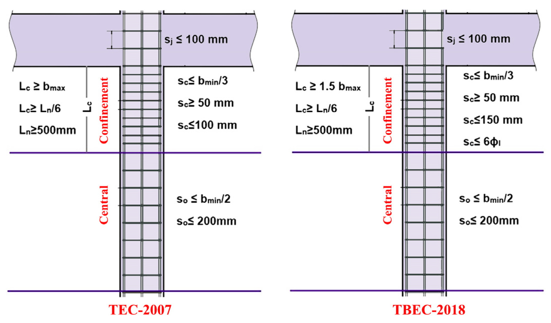
  86. TSDC. Turkish Seismic Design Code; T.C. Resmi Gazete: Ankara, Türkiye, 2007. [Google Scholar]
  87. TBEC. Turkish Building Earthquake Code; T.C. Resmi Gazete: Ankara, Türkiye, 2018. [Google Scholar]
  88. Yenidogan, C. Evaluation of overall seismic performance of rc structures and effectiveness of seismic isolation technology under extreme events: February 6, 2023, earthquakes. Buildings 2025, 15, 990. [Google Scholar] [CrossRef]
  89. Oyguc, E.; Oyguc, R.; Hayir, A. Assessment of a substandard reinforced concrete frame’s beam–column joint using shake table testing. Appl. Sci. 2025, 15, 4168. [Google Scholar] [CrossRef]
  90. Aydin, M.F.; Altindal, A.; Erberik, M.A.; Askan, A. Extreme characteristics of the ground motions recorded during the 2023 Kahramanmaras Turkiye earthquakes and their effect on inelastic seismic response of rc frame buildings. J. Earthq. Eng. 2025, 1–19. [Google Scholar] [CrossRef]
  91. Dedeoglu, I.O.; Yetkin, M.; Tunc, G.; Ozbulut, O.E. Evaluating earthquake-induced damage in Dogansehir, Malatya after 2023 Kahramanmaras earthquake sequence: Geotechnical and structural perspectives. J. Build. Eng. 2025, 104, 112266. [Google Scholar] [CrossRef]
  92. Sivrikaya, O.; Türker, E.; Cüre, E.; Atmaca, E.E.; Angin, Z.; Başağa, H.B.; Altunişik, A.C. Impact of soil conditions and seismic codes on collapsed structures during the 2023 Kahramanmaraş earthquakes: An in-depth study of 400 reinforced concrete buildings. Soil Dyn. Earthq. Eng. 2025, 190, 109119. [Google Scholar] [CrossRef]
  93. Seismosoft. SeismoStruct 2024—A Computer Program for Static and Dynamic Nonlinear Analysis of Framed Structures. 2024. Available online: http://www.seismosoft.com (accessed on 10 October 2024).
  94. Antoniou, S.; Pinho, R. SeismoStruct–Seismic Analysis Program by Seismosoft; Technical User Manuel; SeismoStruct: Pavia, Italy, 2003. [Google Scholar]
  95. Krawinkler, H.; Seneviratna, G.D.P.K. Pros and cons of a pushover analysis of seismic performance evaluation. Eng. Struct. 1998, 20, 452–464. [Google Scholar] [CrossRef]
  96. Chopra, A.K.; Goel, R.K. A modal pushover analysis procedure for estimating seismic demands for buildings. Earthq. Eng. Struct. Dyn. 2002, 31, 561–582. [Google Scholar] [CrossRef]
  97. Elnashai, A.S. Advanced inelastic static (pushover) analysis for earthquake applications. Struct. Eng. Mech. 2001, 12, 51–69. [Google Scholar] [CrossRef]
  98. EN 1998-3; Eurocode-8: Design of Structures for Earthquake Resistance—Part 3: Assessment and Retrofitting of Buildings. European Committee for Standardization: Bruxelles, Belgium, 2005.
Figure 1. The tectonic system in which the Anatolian Block is located (Büyüksaraç et al. [84]).
Buildings 15 01535 g001
Figure 2. Examples of damage caused by insufficient transverse reinforcement.
Buildings 15 01535 g002
Figure 3. Examples of damage from low-strength concrete.
Buildings 15 01535 g003
Figure 4. Examples of out-of-plane damage in columns.
Buildings 15 01535 g004
Figure 5. Plastic hinges occur in the upper-end regions of the column.
Buildings 15 01535 g005
Figure 6. Plastic hinges occur in the lower-end regions of the columns.
Buildings 15 01535 g006
Figure 7. Corroded reinforcement due to insufficient concrete cover thickness and inadequate anchorage.
Buildings 15 01535 g007
Figure 8. Examples of a shear crack.
Buildings 15 01535 g008
Figure 9. Slippage of reinforcements bent at 90° from the longitudinal reinforcements.
Buildings 15 01535 g009
Figure 10. Examples of installations passing through the structural members.
Buildings 15 01535 g010
Figure 11. Spalling of core concrete in columns.
Buildings 15 01535 g011
Figure 12. Examples of damage resulting from poor reinforcement workmanship.
Buildings 15 01535 g012
Figure 13. Use of different types of reinforcement.
Buildings 15 01535 g013
Figure 14. Examples of damage caused by short columns.
Buildings 15 01535 g014
Figure 15. Damage due to the pounding effect.
Buildings 15 01535 g015
Figure 16. Transverse reinforcement requirements for RC columns according to last two seismic design codes [86,87].
Buildings 15 01535 g016
Figure 17. Floor plan and naming of the columns.
Buildings 15 01535 g017
Figure 18. 2D and 3D models of the selected RC structure model.
Buildings 15 01535 g018
Figure 19. The cross-sections of the columns before and after reinforcement.
Buildings 15 01535 g019
Figure 20. Typical pushover and idealized capacity curves (DL: damage limitation; SD: significant damage; NC: near collapse).
Buildings 15 01535 g020
Figure 21. Shear force deformation states and columns exceeding the limit (the number of each figure corresponds to the number of model).
Buildings 15 01535 g021
Figure 22. FRP application in Col10 column.
Buildings 15 01535 g022
Figure 23. Models strengthened with FRP.
Buildings 15 01535 g023
Figure 24. Shear force capacity damage states obtained for the models strengthened with FRP.
Buildings 15 01535 g024
Table 1. Characteristics that remain constant in the RC structure models considered in the study.
ParameterValue
Beams250 × 600 mm
Height of slab (mm)120 mm
Each story height (m)3 m
Concrete cover (mm)25 mm
Columns400 × 500 mm
Longitudinal reinforcement (columns)Corners4Φ20
Top and bottom 4Φ16
Left and right 4Φ16
Longitudinal reinforcement (beams)Lower5Φ12
Upper3Φ12
Sides2Φ12
Stirrup (beam)Φ8/150
Local ground typeZE
Damping ratio5%
Importance classII
Target displacement0.42 m
Table 2. Structural models created for different variables.
Model No.Concrete GradeTransverse
Reinforcement Grade
Transverse
Reinforcement Diameter (mm)
Transverse
Reinforcement Spacing (mm)
Model 1C8/10S2208100
Model 2C8/10S2208200
Model 3C8/10S2208300
Model 4C12/15S2208200
Model 5C16/20S2208200
Model 6C20/25S2208200
Model 7C25/30S2208200
Model 8C30/37S2208200
Model 9C25/30S2208100
Table 3. Results obtained for the structural models.
ModelPeriod (s)Base Shear (kN)K-Elas (kN/m)K-Eff (kN/m)Target Displacement (m)
DLSDNC
Model 10.77568422570.3162,073.6138,806.990.0903620.11591940.2009633
Model 20.77568422556.3562,135.5239,130.430.08998780.11543940.2001311
Model 30.77568422551.2562,010.1739,107.540.09001270.11547130.2001864
Model 40.74022422700.8269,824.2342,504.540.08634320.11076390.1920255
Model 50.71203312805.877,373.5845,615.920.08334720.10692060.1853625
Model 60.68876652882.4783,970.6848,511.710.08082190.1036810.1797462
Model 70.66455552953.4994,468.7952,281.540.0778540.09987370.1731457
Model 80.64504072998.06108,517.7455,964.870.07524940.09653240.1673531
Model 90.66455552952.3794,464.4552,262.820.07786790.09989160.1731768
Table 4. Comparison of shear forces for columns exceeding the limit shear force values.
StoreyColumnModel 1Model 2Model 3Model 4Model 5
DemandLimitDemandLimitDemandLimitDemandLimitDemandLimit
1Col1108.27106.26106.5486.10114.5273.97119.8386.16116.78103.63
Col2124.02122.12122.57102.41129.4688.48134.3895.38120.37102.46
Col3123.92122.01122.47102.27129.3688.34134.2295.17115.47104.46
Col4108.23106.21106.5186.06114.4573.89119.7777.7399.8989.17
Col5170.67152.32171.05124.59163.61109.29181.01163.97188.00176.02
Col6177.20152.55177.76119.36166.19105.95193.36163.28202.47190.49
Col7177.11152.70177.68119.46166.20106.05193.05163.31202.14190.19
Col8170.71155.85171.08124.59163.63109.29181.07164.06188.06176.09
Col9167.63156.69167.54125.50162.61109.50173.63156.10177.64163.41
Col10174.78153.12175.15122.57165.92106.26187.12163.51192.76181.97
Col11174.83153.09175.21122.55165.94106.24187.25163.51192.91182.15
Col12167.65156.69167.56125.50162.62109.49173.67156.14177.69163.46
Col13178.40151.59176.71118.73169.67102.37185.76157.15197.41186.98
Col14182.66149.33180.91115.64171.6697.94193.18152.13208.14187.89
Col15182.66149.33180.91115.64171.6697.94193.17152.13208.13187.89
Col16178.40151.59176.71118.73169.67102.37185.76157.14197.41186.97
2Col1No exceed79.7578.6172.6865.68No exceedNo exceed
Col5162.83162.02162.58127.44159.32115.97166.57149.73171.37162.95
Col9162.78161.88162.04127.57161.67115.92164.51148.01168.08159.54
Col13No exceed134.27110.19131.2097.33142.76140.36151.05150.85
Table 5. Number of columns exceeding the shear force limit.
ModelTotal Number of Columns on the First FloorTotal Number of Columns on the Second FloorExceeded Number of Columns%
Model 11621816
Model 21642018
Model 316420 18
Model 41631917
Model 51631917
Model 61621816
Model 71621816
Model 8There is no exceed0
Model 95054
Table 6. General properties of the used FRP.
ParameterValue
Fiber thickness0.1660 mm
Tensile strength3800 MPa
Tensile Modulus230,000 MPa
Elongation (%)1.50
Weight300 g/m2
Table 7. Comparison of demand and limit shear forces in FRP-strengthened structural models.
StoreyColumnFRP1FRP2FRP3FRP4
DemandLimitDemandLimitDemandLimitDemandLimit
1Col1109.8273.47127.6374.42101.28243.28109.98231.87
Col2125.7089.90132.5385.15116.13259.77126.30248.34
Col3125.6089.71132.5485.09116.10259.62126.13248.10
Col4109.9273.44127.6074.33101.26243.24110.05232.00
Col5168.05111.87126.0793.18175.29281.16172.65264.48
Col6172.39108.67123.5686.26185.20278.02178.66257.49
Col7172.40108.75123.7086.31184.99278.26178.54257.93
Col8168.07111.82126.1093.17175.33281.18172.72264.40
Col9165.57112.20123.5386.34170.40283.15170.61268.94
Col10168.28229.38119.6882.80180.68278.65176.71262.87
Col11171.08109.05119.6482.81180.78278.62176.79262.14
Col12165.75112.11123.5986.35170.43283.15170.59268.87
Col13175.03105.67115.6978.20177.30278.98180.91270.14
Col14178.17101.45103.8570.09182.71274.74186.30266.71
Col15178.15101.43103.9070.11182.70274.74186.29266.74
Col16174.99105.60115.8078.23177.30263.23180.87270.21
2Col178.2366.0777.26237.0181.6168.5285.60235.09
Col5162.34115.8177.26237.01162.32116.14165.09283.01
Col9162.50115.89159.42282.73160.90116.27166.29282.59
Col13132.7197.84132.24268.08137.0499.48137.35265.10
Disclaimer/Publisher’s Note: The statements, opinions and data contained in all publications are solely those of the individual author(s) and contributor(s) and not of MDPI and/or the editor(s). MDPI and/or the editor(s) disclaim responsibility for any injury to people or property resulting from any ideas, methods, instructions or products referred to in the content.

