
Development of Half-Sandwich Panels with Alkali-Activated Ceramic and Slag Wastes: Mechanical and Thermal Characterization

 , ,
, ,  ,
,  , , and
Abstract
1. Introduction
2. Research Significance
3. Materials and Methods
3.1. Materials
3.2. Mixture and Panel Manufacture
3.3. Mechanical Testing Procedures
3.3.1. Compressive Strength
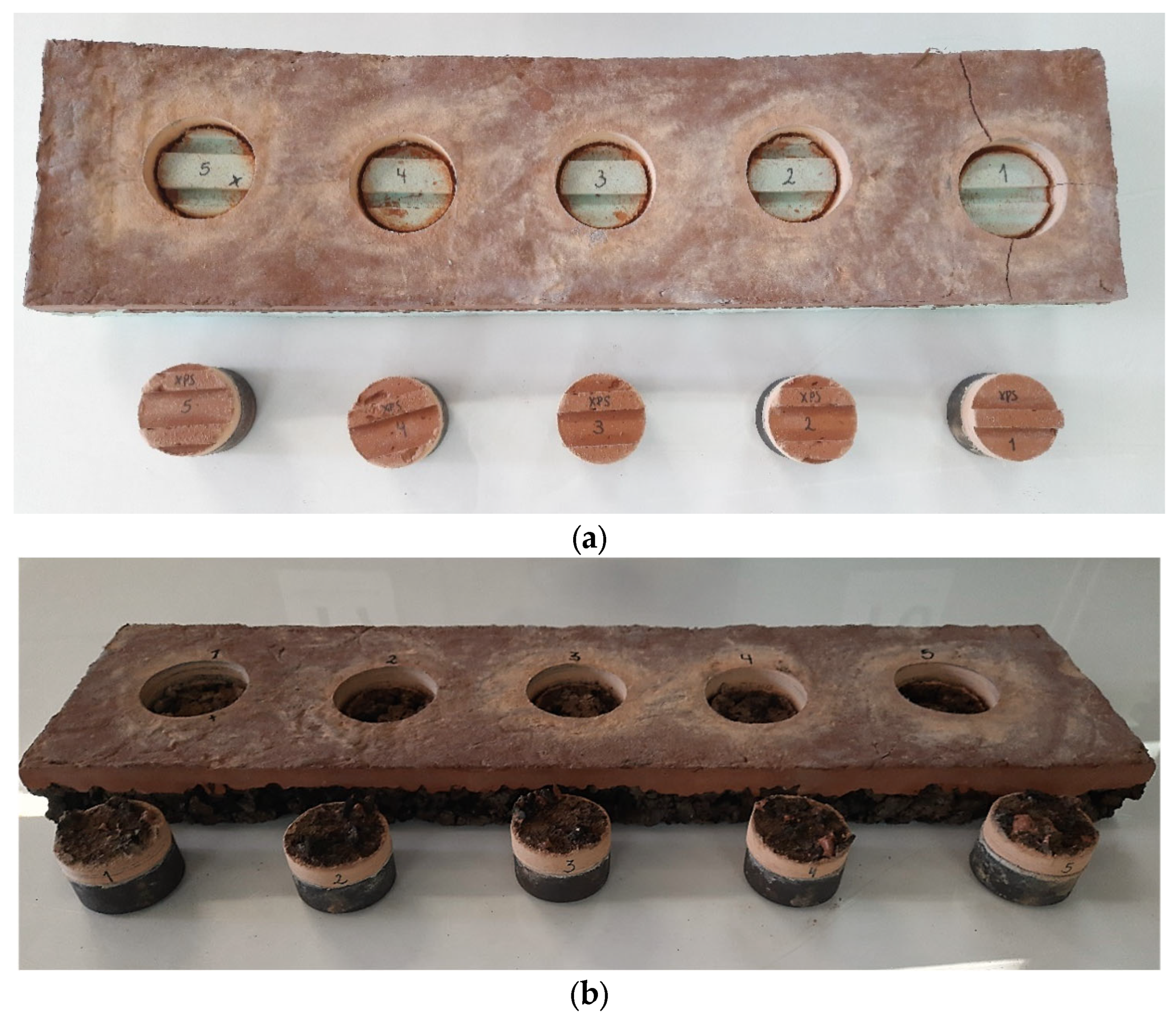
3.3.2. Pull-Off
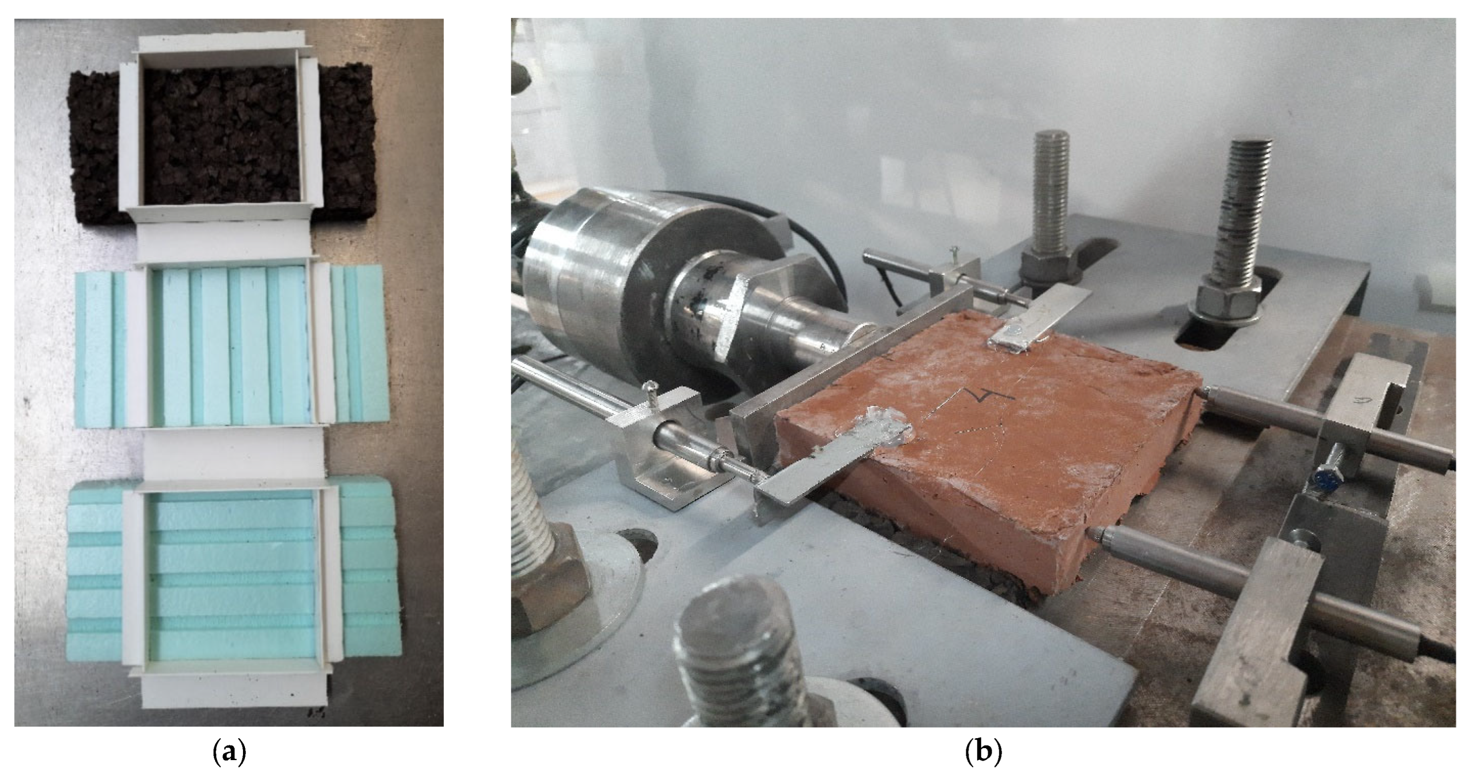
3.3.3. Direct Shear
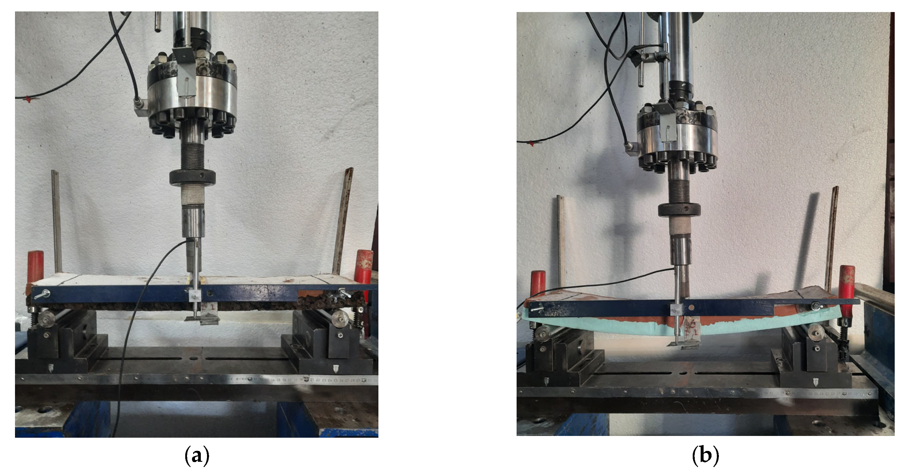
3.3.4. Flexural Behavior
3.4. Thermal Testing Procedures and Analysis
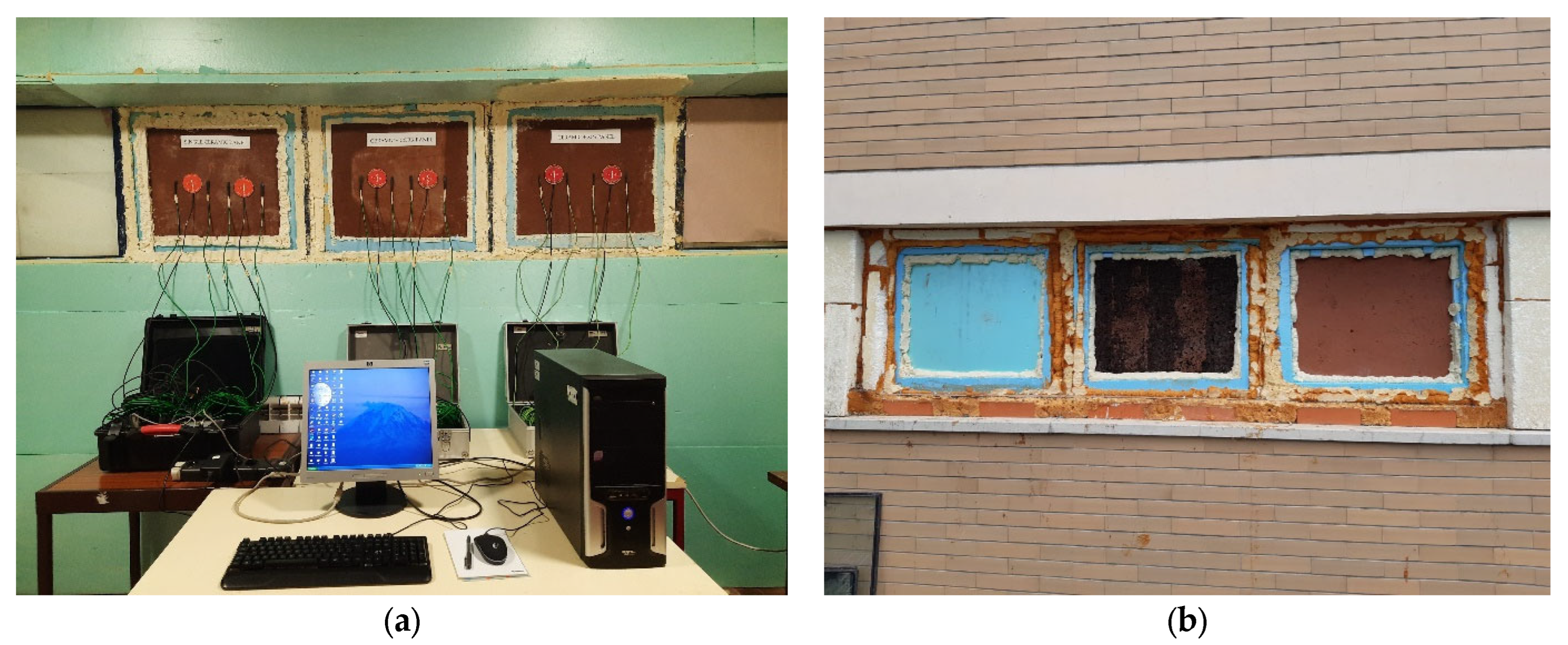
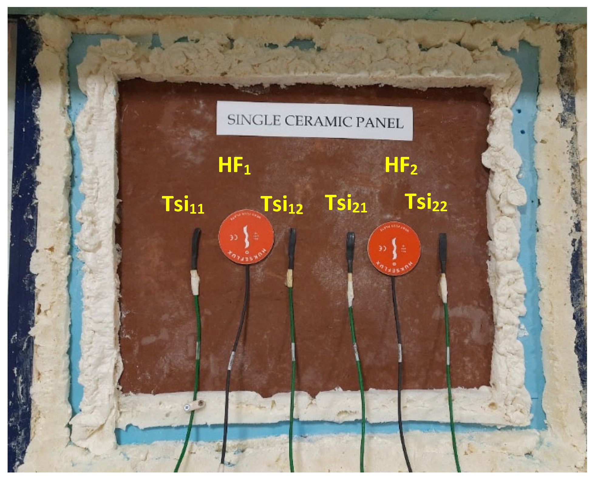
3.4.1. Experimental Set-Up
3.4.2. Analysis Procedure
4. Results and Discussion
4.1. Mechanical Behavior
4.1.1. Pull-Off Tests
4.1.2. Direct Shear Tests
4.1.3. Flexural Behavior
4.2. Thermal Performance
4.2.1. Heat Flux
4.2.2. Inner Surface Temperatures
4.2.3. Thermal Transmission Coefficient
5. Conclusions
- 1.
- The AAc exhibited adequate performance in terms of compressive strength, up to around 37 MPa. It has been demonstrated that the AAc is a viable solution for developing building elements, e.g., non-structural panels, while contributing to a circular economy and sustainability in the construction sector. The grade of strengths achieved even enables its utilization for structural elements.
- 2.
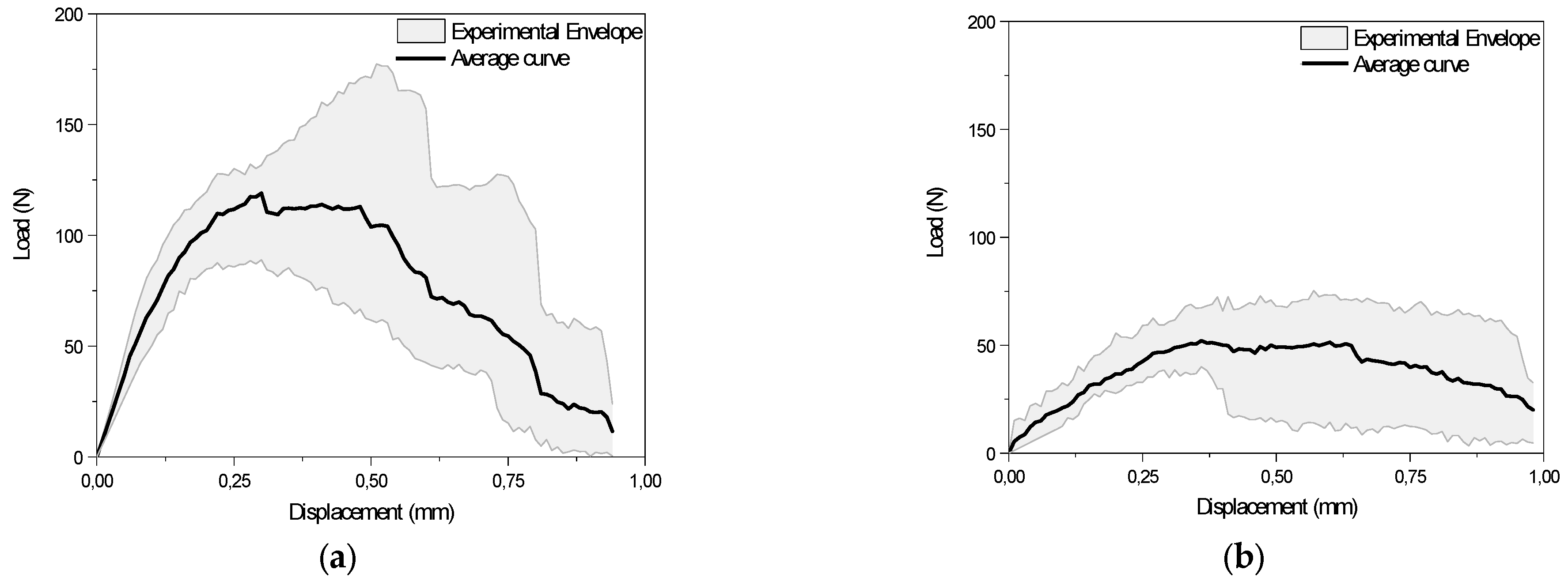
- The pull-off test performed for the two proposed half-sandwich panels, APXPS and APICB, revealed clear differences regarding the type of failure for the specimens with different insulation material typologies. Although higher pull-off load values were reported for APXPS panels than for the APICB, the latter ones exhibited better bond strength when compared to its tensile strength, since the failure occurred outside of the APICB interface region, revealing a weaker internal structure of the ICB. Therefore, the obtained value for the tensile bond strength of APICB can be regarded instead as the tensile strength of the expanded cork agglomerate board itself.
- 3.
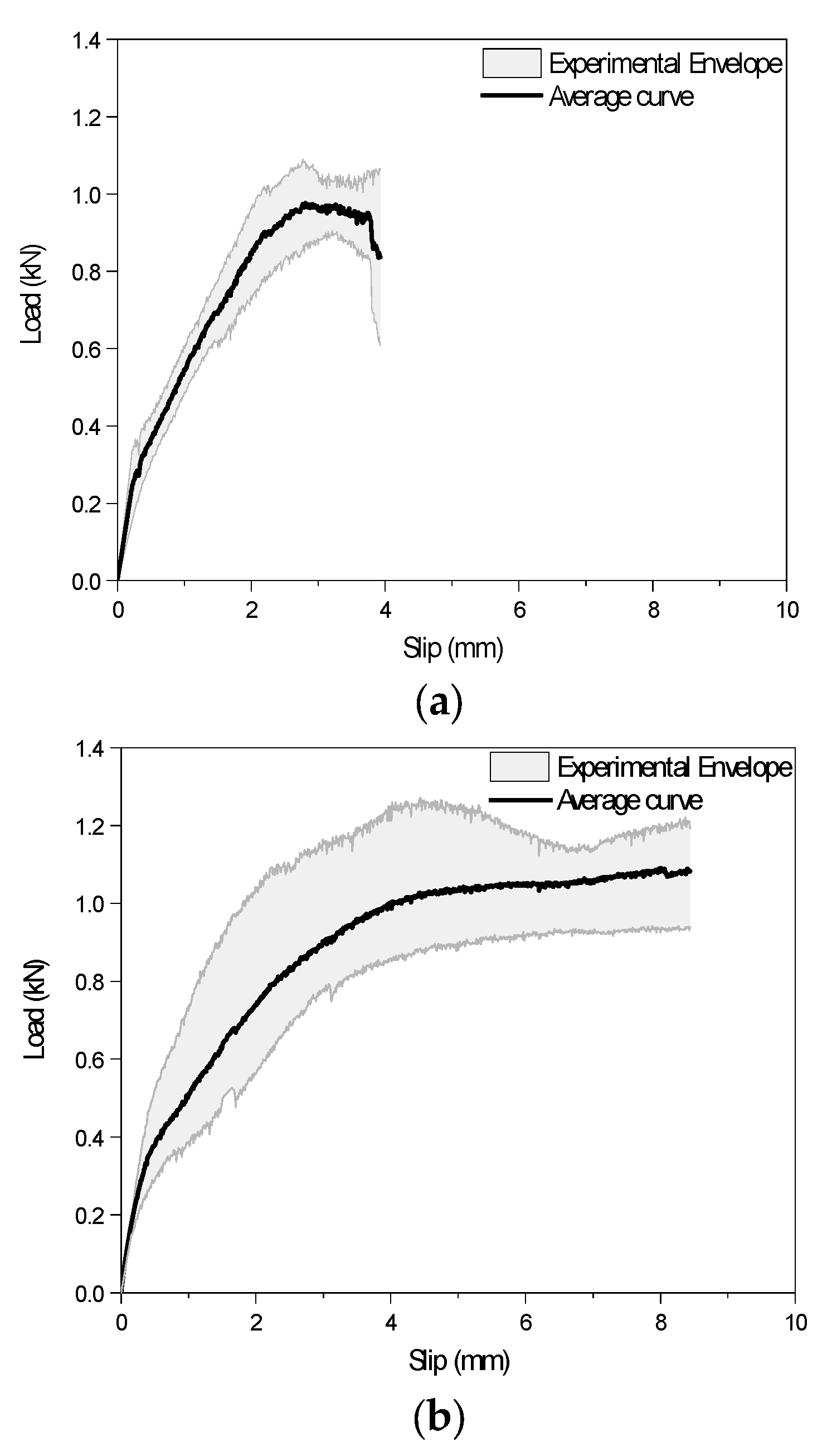
- The direct shear tests showed that the APICB specimens, although having lower bond strength values than the APXPS series, showed high ductility levels. In regard to this matter, it is highlighted that the irregular surface of the ICB, i.e., high porosity, due to the cork granules, had a positive influence on the shear bond-slip behavior since it avoided the unstable interfacial debonding between the panel’s layers. For the direct shear results of the APXPS panels, two distinct behaviors were observed, depending on the orientation of the grooves. When the load was applied perpendicular to the grooves’ orientation (), the shear bond-slip behavior was similar to the one observed for the APICB panels; however, a bond strength nearly two times greater was observed. On the other hand, the bonds in panels were much more fragile, since they relied only on the mobilization of the adhesion and frictional adherence, in opposition to and APICB, where a mechanical component was mobilized due to the grooves and paste that penetrated the ICB pores, respectively.
- 4.
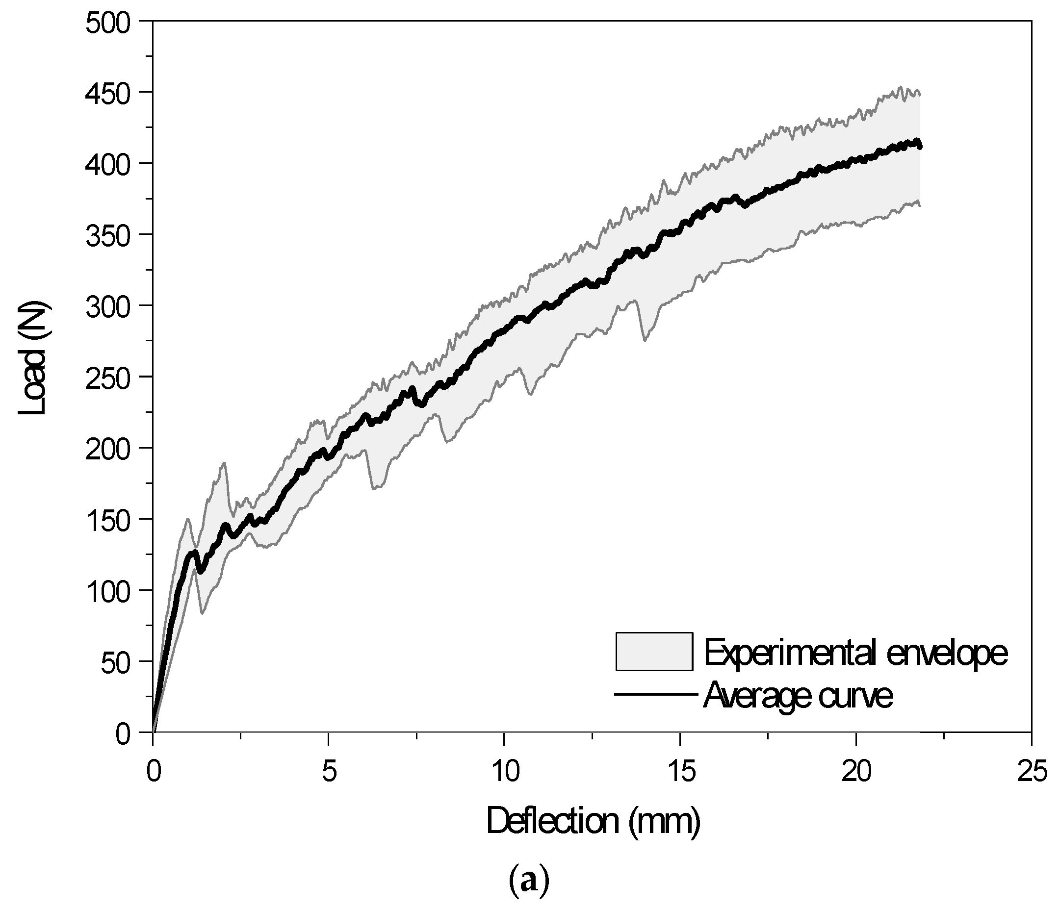
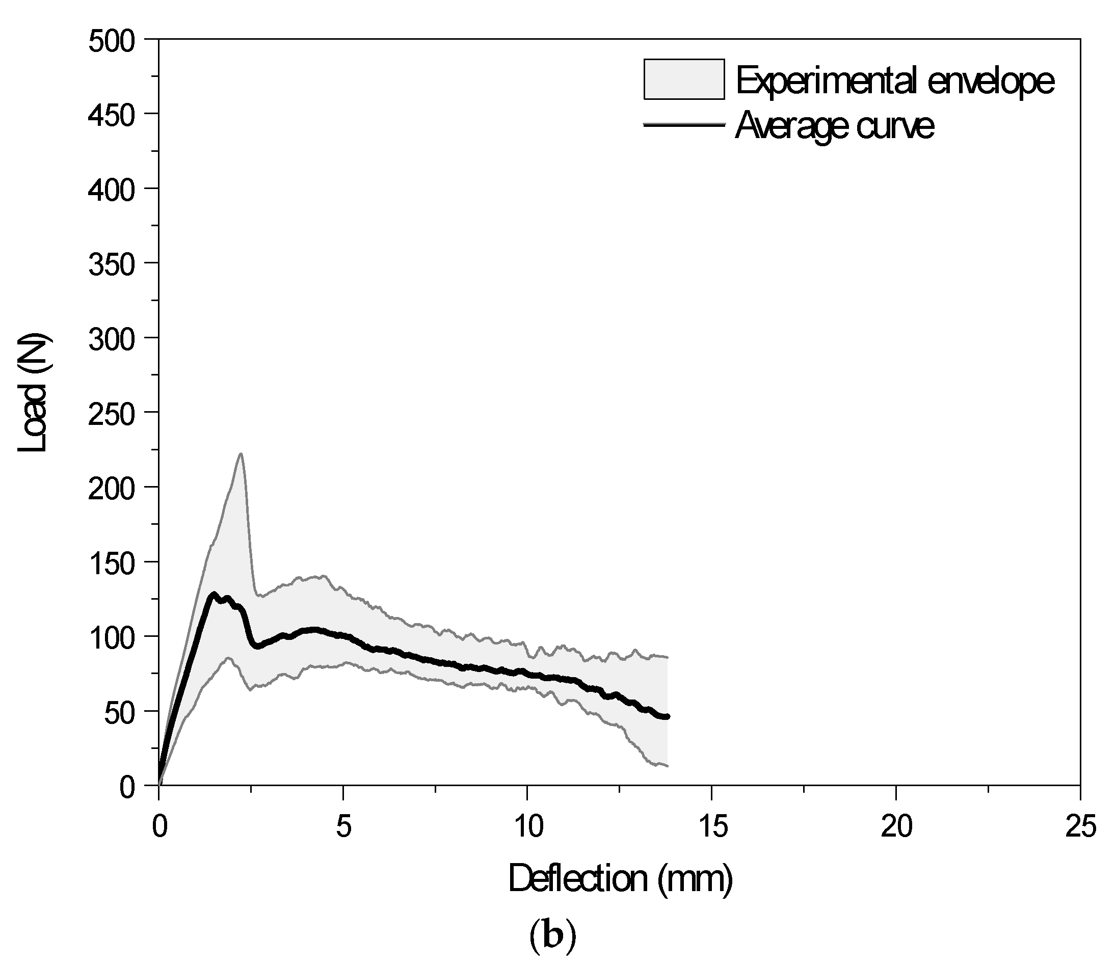
- Different flexural behaviors were identified for the two studied systems, i.e., after the first peak load, the APXPS exhibited a deflection-hardening behavior, while APICB exhibited a softening behavior. Therefore, APXPS showed a higher load-bearing capacity and energy absorption capacity when compared to the APICB.
- 5.
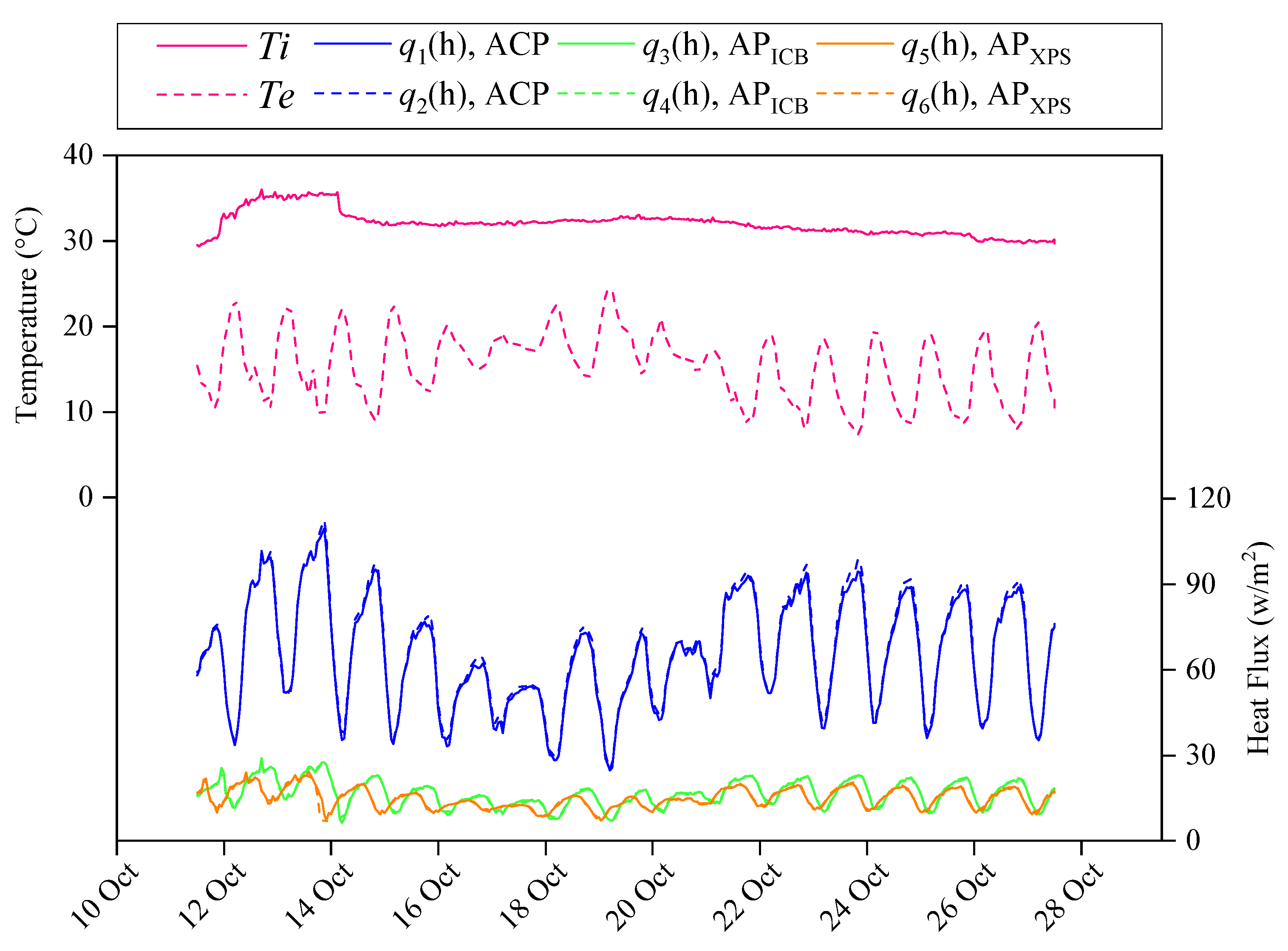
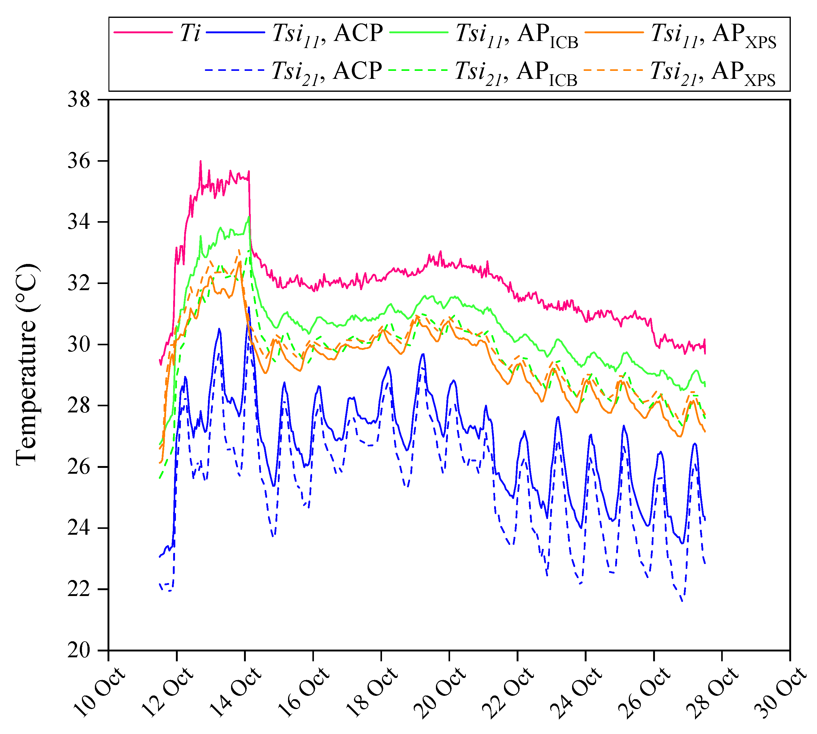
- The thermal performance of the three studied panels was achieved by analyzing heat fluxes, inner surface temperatures, and thermal transmission coefficients. The results of the experimental work showed that the highest oscillation patterns of the heat flux and inner surface temperature curves corresponded to the noninsulated panel (APC), as expected, while no significant differences were detected between the heat flux values of APICB and APXPS. However, slightly larger fluctuations of the heat flux curves of the APICB sample were observed, ascribed to the existing voids in the expanded agglomerated cork insulation panel (due to the origin of its composition) and its higher thermal conductivity value compared to XPS.
- 6.
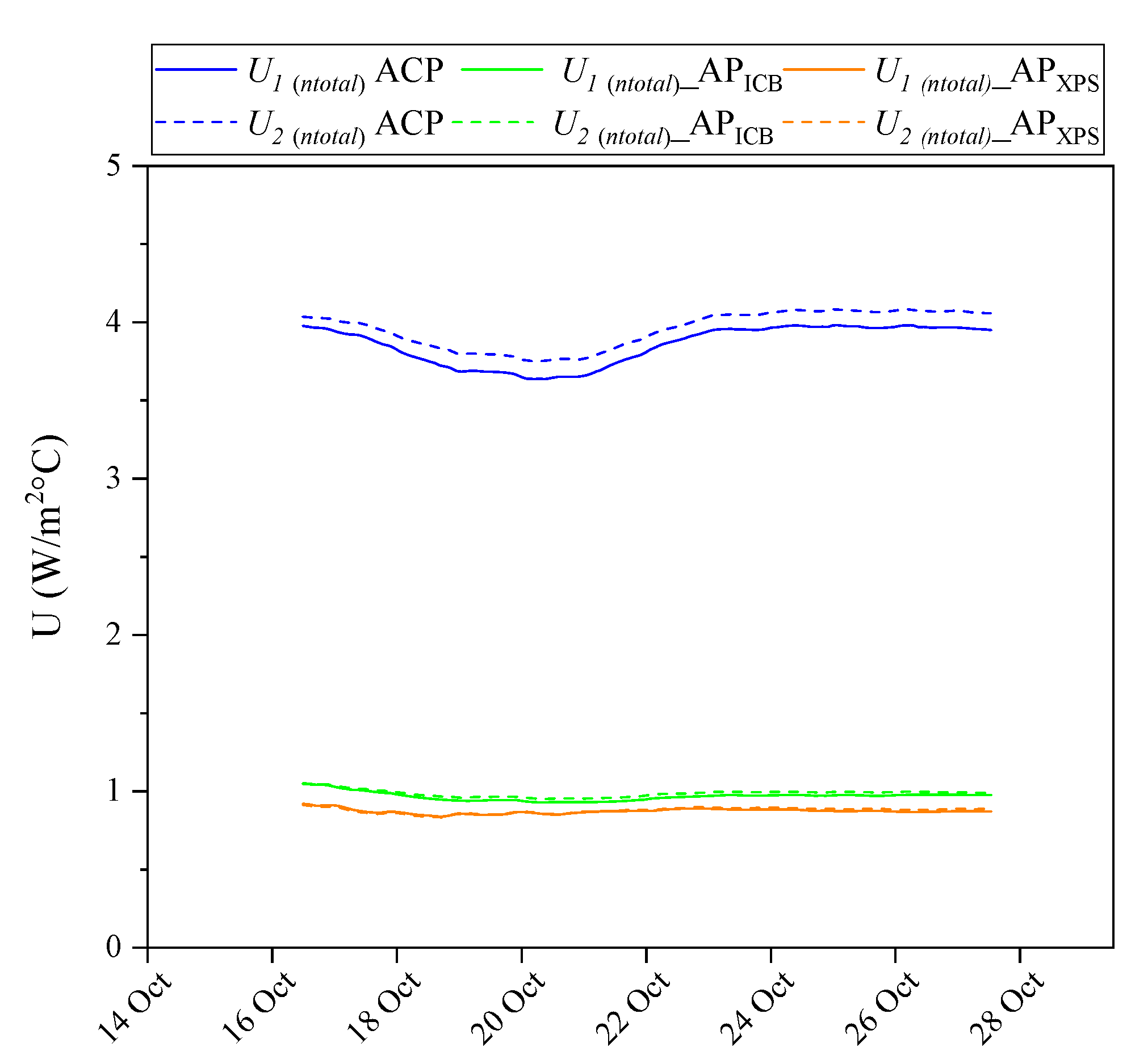
- Thermal resistance values of 1.02 m2 °C/W and 1.14 m2 °C/W for APICB and APXPS were registered, respectively, which are about three times higher than those of ACP (0.26 m2 °C/W). A slight increase (12%) in the R ′(ntotal) for APXPS with respect to APICB was also observed, as expected, given that XPS presents a lower thermal conductivity value. The obtained results of the proposed insulated panels revealed that an improvement in the thermal properties can be achieved, since a thermal resistance of about 2.7 and 3.2 times higher than that of the common hollow ceramic brick wall and the lightweight concrete blocks was detected, respectively, and the thermal resistance is at least 7 times higher when compared to a conventional solution of ceramic solid brick.
- 7.
- A theoretical value of 0.12 W/m °C was calculated for the thermal conductivity of the ACP solution, which is significantly lower than the specified λ of traditional construction materials, such as ceramic materials, standard concrete, the “resistant” insulating concrete, traditional and non-traditional mortars, and renders or plasters, among others. This may suggest that the alkali-activation technology enhances the thermal conductivity of the developed ceramic waste-/slag-based cement.
Author Contributions
Funding
Data Availability Statement
Acknowledgments
Conflicts of Interest
References
- Zhang, Z.; Provis, J.L.; Reid, A.; Wang, H. Geopolymer foam concrete: An emerging material for sustainable construction. Constr. Build. Mater. 2014, 56, 113–127. [Google Scholar] [CrossRef]
- Zannerni, G.M.; Fattah, K.P.; Al-Tamimi, A.K. Ambient-cured geopolymer concrete with single alkali activator. Sustain. Mater. Technol. 2020, 23, e00131. [Google Scholar] [CrossRef]
- Villaquirán-Caicedo, M.A.; de Gutiérrez, R.M. Synthesis of ceramic materials from ecofriendly geopolymer precursors. Mater. Lett. 2018, 230, 300–304. [Google Scholar] [CrossRef]
- Ceramic World Web. World Production and Consumption of Ceramic Tiles. 2023. Available online: https://ceramicworldweb.com/en/economics-and-markets/world-production-and-consumption-ceramic-tiles-2023 (accessed on 19 September 2024).
- Senthamarai, R.M.; Manoharan, P.D. Concrete with ceramic waste aggregate. Cem. Concr. Compos. 2005, 27, 910–913. [Google Scholar] [CrossRef]
- Hwang, C.L.; Yehualaw, M.D.; Vo, D.H.; Huynh, T.P.; Largo, A. Performance evaluation of alkali activated mortar containing high volume of waste brick powder blended with ground granulated blast furnace slag cured at ambient temperature. Constr. Build. Mater. 2019, 223, 657–667. [Google Scholar] [CrossRef]
- Huseien, G.F.; Sam, A.R.M.; Shah, K.W.; Mirza, J.; Tahir, M.M. Evaluation of alkali-activated mortars containing high volume waste ceramic powder and fly ash replacing GBFS. Constr. Build. Mater. 2019, 210, 78–92. [Google Scholar] [CrossRef]
- Fang, K.; Wang, D.; Zhao, J.; Zhang, M. Utilization of ladle furnace slag as cement partial replacement: Influences on the hydration and hardening properties of cement. Constr. Build. Mater. 2021, 299, 124265. [Google Scholar] [CrossRef]
- Sarkar, M.; Dana, K. Partial replacement of metakaolin with red ceramic waste in geopolymer. Ceram. Int. 2021, 47, 3473–3483. [Google Scholar] [CrossRef]
- Azevedo, A.R.G.; Vieira, C.M.F.; Ferreira, W.M.; Faria, K.C.P.; Pedroti, L.G.; Mendes, B.C. Potential use of ceramic waste as precursor in the geopolymerization reaction for the production of ceramic roof tiles. J. Build. Eng. 2020, 29, 101156. [Google Scholar] [CrossRef]
- Amin, S.K.; El-Sherbiny, S.A.; El-Magd, A.A.M.A.; Belal, A.; Abadir, M.F. Fabrication of geopolymer bricks using ceramic dust waste. Constr. Build. Mater. 2017, 157, 610–620. [Google Scholar] [CrossRef]
- Mendes, J.P.; Elyseu, F.; Nieves, L.J.J.; Zaccaron, A.; Bernardin, A.M.; Angioletto, E. Synthesis and characterization of geopolymers using clay ceramic waste as source of aluminosilicate. Sustain. Mater. Technol. 2021, 28, e00264. [Google Scholar] [CrossRef]
- Sun, Z.; Lin, X.; Liu, P.; Wang, D.; Vollpracht, A.; Oeser, M. Study of alkali activated slag as alternative pavement binder. Constr. Build. Mater. 2018, 186, 626–634. [Google Scholar] [CrossRef]
- Shojaei, M.; Behfarnia, K.; Mohebi, R. Application of alkali-activated slag concrete in railway sleepers. Mater. Des. 2015, 69, 89–95. [Google Scholar] [CrossRef]
- Gaibor, N.; Leitão, D.; Miranda, T.; Cristelo, N.; Pereira, E.N.B.; Cunha, V.M.C.F. Effect of polyacrylonitrile fiber on the properties of alkali-activated ceramic/slag-based mortar. J. Build. Eng. 2021, 44, 103367. [Google Scholar] [CrossRef]
- Gaibor, N.; Leitão, D.; Miranda, T.; Cristelo, N.; Fernandes, L.; Pereira, E.N.; Cunha, V.M. Fiber Reinforced Alkali Activated Cements from Ceramic Waste and Ladle Furnace Slag without thermal curing. J. Mater. Civ. Eng. 2023, 35, 04023271. [Google Scholar] [CrossRef]
- Huseien, G.F.; Sam, A.R.M.; Shah, K.W.; Asaad, M.A.; Tahir, M.M.; Mirza, J. Properties of ceramic tile waste based alkali-activated mortars incorporating GBFS and fly ash. Constr. Build. Mater. 2019, 214, 355–368. [Google Scholar] [CrossRef]
- Huseien, G.F.; Sam, A.R.M.; Shah, K.W.; Mirza, J. Effects of ceramic tile powder waste on properties of self-compacted alkali-activated concrete. Constr. Build. Mater. 2020, 236, 117574. [Google Scholar] [CrossRef]
- Shah, K.W.; Huseien, G.F. Bond strength performance of ceramic, fly ash and GBFS ternary wastes combined alkali-activated mortars exposed to aggressive environments. Constr. Build. Mater. 2020, 251, 119088. [Google Scholar] [CrossRef]
- Rakhimova, N.R.; Rakhimov, R.Z. Alkali-activated cements and mortars based on blast furnace slag and red clay brick waste. Mater. Des. 2015, 85, 324–331. [Google Scholar] [CrossRef]
- Zedan, S.R.; Mohamed, M.R.; Ahmed, D.A.; Mohammed, A.H. Effect of demolition/construction wastes on the properties of alkali activated slag cement. HBRC J. 2017, 13, 331–336. [Google Scholar] [CrossRef]
- Gaibor, N.; Coelho, J.; Leitão, D.; Miranda, T.; Tavares, P.; Cristelo, N. Alkali activation of recycled ceramic aggregates from construction and demolition wastes. Mater. Constr. 2020, 70, 222. [Google Scholar] [CrossRef]
- Lu, C.; Zhang, Z.; Deng, Y.; Hu, J.; Yu, Q.; Shi, C. Effects of silica fume/ultrafine fly ash on the rheology and hardening of alkali-activated slag-waste ceramic powder paste. Constr. Build. Mater. 2024, 438, 137265. [Google Scholar] [CrossRef]
- Sierra-Pérez, J.; Boschmonart-Rives, J.; Gabarrell, X. Environmental assessment of façade-building systems and thermal insulation materials for different climatic conditions. J. Clean. Prod. 2016, 113, 102–113. [Google Scholar] [CrossRef]
- European Parliament and Council. Directive 2010/31/EU of the European Parliament and of the Council of 19 May 2010 on the Energy Performance of Buildings; European Union: Brussels, Belgium, 2010. [Google Scholar]
- European Parliament and Council. Directive (EU) 2018/844 of the European Parliament and of the Council of 30 May 2018 amending Directive 2010/31/EU on the Energy Performance of Buildings and Directive 2012/27/EU on Energy Efficiency; European Union: Brussels, Belgium, 2018. [Google Scholar]
- Tártaro, A.S.; Mata, T.M.; Martins, A.A.; da Silva, J.C.G.E. Carbon footprint of the insulation cork board. J. Clean. Prod. 2017, 143, 925–932. [Google Scholar] [CrossRef]
- Papadopoulos, A.M. State of the art in thermal insulation materials and aims for future developments. Energy Build. 2005, 37, 77–86. [Google Scholar] [CrossRef]
- Llantoy, N.; Chàfer, M.; Cabeza, L.F. A comparative life cycle assessment (LCA) of different insulation materials for buildings in the continental Mediterranean climate. Energy Build. 2020, 225, 110323. [Google Scholar] [CrossRef]
- Palahí, M.; Birot, Y.; Bravo, F.; Gorriz, E. Modelling, Valuing and Managing Mediterranean Forest Ecosystems for Non-Timber Goods and Services. In Proceedings of the European Forest Institute Series, EFI Proceedings No. 57, Palencia, Spain, 26–27 October 2007; Päivinen, R., Korhonen, M., Pajari, B., Eds.; European Forest Institute: Joensuu, Finland, 2009. [Google Scholar]
- Gil, L. New Cork-Based Materials and Applications. Materials 2015, 8, 625–637. [Google Scholar] [CrossRef] [PubMed]
- Anjos, O.; Pereira, H.; Rosa, M.E. Tensile properties of cork in the tangential direction: Variation with quality, porosity, density and radial position in the cork plank. Mater. Des. 2010, 31, 2085–2090. [Google Scholar] [CrossRef]
- Schiavoni, S.; D’Alessandro, F.; Bianchi, F.; Asdrubali, F. Insulation materials for the building sector: A review and comparative analysis. Renew. Sustain. Energy Rev. 2016, 62, 988–1011. [Google Scholar] [CrossRef]
- Dickson, T.; Pavía, S. Energy performance, environmental impact and cost of a range of insulation materials. Renew. Sustain. Energy Rev. 2021, 140, 110752. [Google Scholar] [CrossRef]
- Kumar, S.; Chen, B.; Xu, Y.; Dai, J.G. Structural behavior of FRP grid reinforced geopolymer concrete sandwich wall panels subjected to concentric axial loading. Compos. Struct. 2021, 270, 114117. [Google Scholar] [CrossRef]
- Cui, Y.; Hao, H.; Li, J.; Chen, W.; Zhang, X. Structural behavior and vibration characteristics of geopolymer composite lightweight sandwich panels for prefabricated buildings. J. Build. Eng. 2022, 57, 104872. [Google Scholar] [CrossRef]
- Kumar, S.; Chen, B.; Xu, Y.; Dai, J.G. Axial-flexural behavior of FRP grid-reinforced geopolymer concrete sandwich wall panels enabled with FRP connectors. J. Build. Eng. 2022, 47, 103907. [Google Scholar] [CrossRef]
- Cui, Y.; Hao, H.; Li, J.; Chen, W. Failure mechanism of geopolymer composite lightweight sandwich panel under flexural and edgewise compressive loads. Constr. Build. Mater. 2021, 270, 121496. [Google Scholar] [CrossRef]
- Huang, J.Q.; Dai, J.G. Flexural performance of precast geopolymer concrete sandwich panel enabled by FRP connector. Compos. Struct. 2020, 248, 112563. [Google Scholar] [CrossRef]
- Ranjbar, N.; Zhang, M. Fiber-reinforced geopolymer composites: A review. Cem. Concr. Compos. 2020, 107, 103498. [Google Scholar] [CrossRef]
- EN 13164:2012; Thermal Insulation Products for Buildings—Factory Made Extruded Polystyrene Foam. European Committee for Standardization (CEN): Brussels, Belgium, 2012. Available online: https://standards.iteh.ai/catalog/standards/cen/529f73f8-a7e5-447f-9fd3-a923c7ac58bf/en-13164-2012 (accessed on 23 November 2021).
- EN13170:2012+A1:2015; Thermal Insulation Products for Buildings-Factory Made Products of Expanded Cork (ICB). European Committee for Standardization (CEN): Brussels, Belgium, 2015. Available online: https://standards.iteh.ai/catalog/standards/cen/49ba9cdb-6a4b-424a-9d4c-741cea3f2d43/en-13170-2012a1-2015 (accessed on 23 November 2021).
- IBERFIBRAN. FIBRANxps 300 C. Ficha Técnica; IBERFIBRAN: Ovar, Portugal, 2021; Available online: https://fibran.pt/wp-content/uploads/sites/10/2021/10/FT_300C_PT.pdf (accessed on 21 January 2022).
- Amorim, C.I.; Expanded Insulation Corkboard. Technical Sheet, Mozelos, Portugal. 2021. Available online: www.amorimcorkinsulation.com (accessed on 22 November 2021).
- Danosa España. Environmental Product Declaration of DANOPREN® Extruded Polystyrene (XPS) Insulation Board; Danosa España: Fontanar, Spain, 2019; Available online: https://www.danosa.com/global/wp-content/uploads/sites/9/2021/12/Danosa_EDP_danopren.pdf (accessed on 20 February 2022).
- BS EN 12350-8; Testing Fresh Concrete—Part 8: Self-Compacting Concrete—Slump-Flow Test. European Committee for Standardization (CEN): London, UK, 2019.
- ASTM International. Standard Test Method for Compressive Strength of Cylindrical Concrete Specimens (ASTM C39/C39M—18); ASTM International: West Conshohocken, PA, USA, 2018. [Google Scholar]
- ISO 9869-1:2014; Thermal Insulation—Building Elements—In-Situ Measurement of Thermal Resistance and Thermal Transmittance, Part 1: Heat Flow Meter Method. International Organization for Standardization (ISO): Geneva, Switzerland, 2014.
- Leitão, D.; Barbosa, J.; Soares, E.; Miranda, T.; Cristelo, N.; Briga-Sá, A. Thermal performance assessment of masonry made of ICEB’s stabilised with alkali-activated fly ash. Energy Build. 2017, 139, 44–52. [Google Scholar] [CrossRef]
- Ramos, A.; Briga-Sá, A.; Pereira, S.; Correia, M.; Pinto, J.; Bentes, I.; Teixeira, C.A. Thermal performance and life cycle assessment of corn cob particleboards. J. Build. Eng. 2021, 44, 102998. [Google Scholar] [CrossRef]
- Santos, L.M.C. Coeficientes de Transmisssão Térmica de Elementos da Envolvente dos Edifícios Colecção Edifícios–ITE 50, Lisbon. 2006. Available online: https://www.scribd.com/doc/283939592/Coeficientes-de-Transmissao-Termica-de-Elementos-Da-Envolvente-Dos-Edificios-LNEC-ITE-50 (accessed on 19 January 2022).
- Kazem, H.; Bunn, W.G.; Seliem, H.M.; Rizkalla, S.H.; Gleich, H. Durability and long term behavior of FRP/foam shear transfer mechanism for concrete sandwich panels. Constr. Build. Mater. 2015, 98, 722–734. [Google Scholar] [CrossRef]
- Hwang, C.L.; Yehualaw, M.D.; Vo, D.H.; Huynh, T.P. Development of high-strength alkali-activated pastes containing high volumes of waste brick and ceramic powders. Constr. Build. Mater. 2019, 218, 519–529. [Google Scholar] [CrossRef]
- Li, X.; Yan, L.; Zhang, Y.; Yang, X.; Guo, A.; Du, H.; How, F.; Liu, J. Lightweight porous silica ceramics with ultra-low thermal conductivity and enhanced compressive strength. Ceram. Int. 2022, 48, 9788–9796. [Google Scholar] [CrossRef]
- Pommer, V.; Vejmelková, E.; Černý, R.; Keppert, M. Alkali-activated waste ceramics: Importance of precursor particle size distribution. Ceram. Int. 2021, 47, 31574–31582. [Google Scholar] [CrossRef]


| Ceramic Waste Type | Precursor (wt. Ratio), CW:S | Alkali Activator | Compressive Strength, 28 Days, MPa | Curing Conditions/Temperature | Reference |
|---|---|---|---|---|---|
| Tile waste | 50:50 60:40 70:30 | NaOH (4M) 2:Na2SiO3, mass % 0.75 | Up to 73 Up to 68 Up to 32 | Ambient T, 27 °C | [17] |
| 70:30 | NaOH (2M) 2:Na2SiO3, mass % 0.75 | Up to 34 | Cured in air | [18] | |
| 50:50 60:40 70:30 | NaOH (4M) 2:Na2SiO3 | Up to 73 Up to 68 Up to 32 | Ambient T, 25 °C | [19] | |
| Red clay brick waste from the brick-making plant | 20:80 40:60 60:40 80:20 | Na2SiO3 + Na2CO3 (SiO2/Na2O, silica modulus of 1.5) | Up to 100 Up to 96 Up to 70 Up to 40 | Room T or steam curing | [20] |
| Waste brick powder | 100–50 1 | NaOH (10M) 2 + Na2SiO3 | Ranged from 24 to 93 MPa | Ambient T, 25 °C | [6] |
| Ceramic waste andred clay brick waste | 10:90 | Na2SiO3 + Na2CO3 | Up to 80 Up to 83 | 37 ± 2 °C for 24 h, then tap water at 23 ± 2 °C | [21] |
| Ceramic waste from CDW | 75:25 50:50 25:75 | NaOH (8M) 2 [SH] or Na2SiO3 [SS] | [SH]; [SS] 18; 50 15; 50 5; 38 | 70 ± 2 °C for 24 h, then ambient T, 21 ± 2 °C | [22] |
| Waste building ceramics | 50:50 | NaOH (2M) 2 Na2CO3 (99%) | Up to 88 | Standard conditions, 20 ± 2 °C | [23] |
| XPS | ICB | |
|---|---|---|
| Density (kg/m3) | 30 to 33 | +/−110 |
| Compressive strength (kPa) at 10% deformation | 300 | ≥100 |
| Tensile strength (kN/m2) | 50 to 80 | ≥600 |
| Thermal conductivity (W/m·K) | 0.033 | 0.039 |
| Water permeability | High resistance to water absorption Satisfactory diffusion of water vapor | Water absorption Permeability to water vapor |
| Reaction to fire | Euroclass E | Euroclass E |
| Environmental properties | 100% recyclable 50-year durability Produced without CFCs and HCFCs GWP: 2.57 kg CO2-Eq/1 m2 XPS board [45] | 100% natural and fully recyclable Almost unlimited durability CO2 sink (carbon-negative) |
| Precursor | Activator | SP | Water | PANf | |
|---|---|---|---|---|---|
| CW | LFS | SS | |||
| 499.2 | 166.4 | 299.5 | 13.3 | 15.0 | 6.7 |
| Equation n° | Parameter | Units | Equation | Description |
|---|---|---|---|---|
| (1) | Thermal transmission coefficient (U) | W/m2 °C | q(n): heat flow through the sample for the instant n Ti(n): interior temperature Te(n): exterior temperature ntotal: total number of instants of registered data during the experiment Applied to each HFi data set | |
| (2) | Thermal transmission coefficient of each panel (U′) | W/m2 °C | Use values from Equation (1) Applied to HF1 and HF2 data set | |
| (3) | Thermal resistance (R′) for each panel | (m2 °C/W) | Use value from Equation (2) | |
| (4) | Thermal resistance of the ACP layer (R′ACP) | (m2 °C/W) | = | Use value from Equation (3) : 0.04 m2 °C/W [51] : 0.13 m2 °C/W [51] R′ ACP is estimated for the ACP layer |
| (5) | Thermal conductivity (λ) | (W/m °C) | : thickness of the ACP : ACP thermal resistance from Equation (4) |
| Panel ID | Shear Bond Strength (τavg) [kPa] (CoV, %) | Interfacial Tensile Strength [kPa] (CoV, %) | |
|---|---|---|---|
| APXPS | 89.0 (13.8) | 86.4 (29.8) | |
| 79.3 (8.6) | |||
| APICB | 46.4 (1.0) | 52.4 (15.2) | |
| Panel ID | Ti (°C) | Te (°C) | Tsi (°C) | qi (W/m2) | U′(ntotal) (W/m2 °C) | R′(ntotal) (m2 °C/W) | R′ACP (m2 °C/W) | λACP (W/m °C) |
|---|---|---|---|---|---|---|---|---|
| ACP | 32.04 | 15.37 | 26.15 | 65.94 | 3.91 | 0.26 | 0.09 | 0.12 |
| APICB | 30.14 | 16.64 | 0.98 | 1.02 | - | - | ||
| APXPS | 29.62 | 14.86 | 0.88 | 1.14 | - | - |
| Building Solution | ρ (kg/m³) | R′(ntotal) (m2 °C/W) | λ (W/m °C) | |
|---|---|---|---|---|
| Developed alkali-activated material | ACP | 1950 | 0.26 | 0.12 |
| APICB | 1.02 | - | ||
| APXPS | 1.14 | - | ||
| Traditional masonry elements (0.10–0.11) m | Hollow ceramic bricks | - | 0.27 | - |
| Solid ceramic bricks | - | 0.13 | - | |
| Concrete blocks | - | 0.16 | - | |
| Lightweight concrete blocks | - | 0.27 | - | |
| Traditional construction materials | Ceramic materials used for bricks, blocks, roof tiles, and tiles | 1800–2000 | - | 0.77 |
| Standard concrete | 2000–2300 | - | 1.65 | |
| Conventional cavernous concrete | 1800–2000 | - | 1.35 | |
| Cavernous concrete, with expanded clay aggregate, light sand, and no river sand | 800–1000 | - | 0.33 | |
| “Resistant” insulating concrete with expanded clay aggregate, light sand, and no river sand “Resistant” insulating concrete with light sand and river sand (≤10%) | 1200 1200–1400 | - | 0.46 0.70 | |
| Perlite or expanded vermiculite aggregate concrete | 400–600 600–800 | - | 0.24 0.31 | |
| Traditional mortars and renders or plasters | 1800–2000 | - | 1.3 | |
| Non-traditional mortars and renders or plasters | 1600–1800 | - | 1.0 | |
| Fiber cement boards with asbestos fibers | 1800–2200 | - | 0.95 | |
| Fiber cement boards with cellulosic fibers | 1400–1800 | - | 0.46 | |
| Plywood panels | 1000 | - | 0.24 | |
Disclaimer/Publisher’s Note: The statements, opinions and data contained in all publications are solely those of the individual author(s) and contributor(s) and not of MDPI and/or the editor(s). MDPI and/or the editor(s) disclaim responsibility for any injury to people or property resulting from any ideas, methods, instructions or products referred to in the content. |
© 2025 by the authors. Licensee MDPI, Basel, Switzerland. This article is an open access article distributed under the terms and conditions of the Creative Commons Attribution (CC BY) license (https://creativecommons.org/licenses/by/4.0/).
Share and Cite
Gaibor, N.; Leitão, D.; Briga-Sá, A.; Miranda, T.; Cristelo, N.; Pereira, E.N.B.; Cunha, V.M.C.F. Development of Half-Sandwich Panels with Alkali-Activated Ceramic and Slag Wastes: Mechanical and Thermal Characterization. Buildings 2025, 15, 1469. https://doi.org/10.3390/buildings15091469
Gaibor N, Leitão D, Briga-Sá A, Miranda T, Cristelo N, Pereira ENB, Cunha VMCF. Development of Half-Sandwich Panels with Alkali-Activated Ceramic and Slag Wastes: Mechanical and Thermal Characterization. Buildings. 2025; 15(9):1469. https://doi.org/10.3390/buildings15091469
Chicago/Turabian StyleGaibor, Norma, Dinis Leitão, Ana Briga-Sá, Tiago Miranda, Nuno Cristelo, Eduardo N. B. Pereira, and Vítor M. C. F. Cunha. 2025. "Development of Half-Sandwich Panels with Alkali-Activated Ceramic and Slag Wastes: Mechanical and Thermal Characterization" Buildings 15, no. 9: 1469. https://doi.org/10.3390/buildings15091469
APA StyleGaibor, N., Leitão, D., Briga-Sá, A., Miranda, T., Cristelo, N., Pereira, E. N. B., & Cunha, V. M. C. F. (2025). Development of Half-Sandwich Panels with Alkali-Activated Ceramic and Slag Wastes: Mechanical and Thermal Characterization. Buildings, 15(9), 1469. https://doi.org/10.3390/buildings15091469