Abstract
Building drainage systems are essential for protecting occupant health and indoor air quality. While recent studies have focused on high-rise drainage dynamics and riser offset mitigation, ventilation components—particularly appliance vent pipes—remain underexplored. This study employed a full-scale proportional drainage experimental tower to assess appliance vent pipes on horizontal branches as a strategy for water seal protection in dual-riser systems. Maximum drainage capacities were quantified under varying pipe positions and diameters (DN50, DN75, DN100), alongside analyses of pressure transients and water seal losses. Results indicate that appliance vent pipes increase maximum drainage capacity from 6.5 L/s (baseline cast iron dual-riser) to 7.5 L/s, a 1.0 L/s gain, though improvements are modest. Position does not affect capacity (uniformly 7.5 L/s across configurations) but profoundly influences water seal losses: P-type trap placement yields the lowest losses on most floors, combined P-type trap/floor drain placement achieves intermediate values, and floor drain placement the highest. Thus, the P-type trap is optimal. Diameter similarly has no impact on capacity but shows nuanced effects on seals; DN75 minimizes losses on most floors, outperforming DN50 and DN100, indicating that appliance vent pipe design should adopt a height-zoned approach tailored to anticipated drainage loads and pressure characteristics. Appliance vent pipes effectively dampen positive/negative pressure fluctuations, reducing seal depletion and sewer gas risks. These findings guide engineering designs for healthier indoor environments in high-rise buildings.
1. Introduction
People spend 80–90% of their time in indoor environments, with more than 60% of this duration occurring in residential buildings [1]. This underscores the profound influence of indoor environmental quality on human health. The proliferation of high-rise and super high-rise buildings has substantially increased instantaneous drainage loads on their plumbing systems, resulting in more frequent hygiene and safety issues, such as odor reversion and blockages [2]. These challenges starkly contrast with residents’ escalating demands for healthy and comfortable living environments. Consequently, the safety and reliability of building drainage systems—as a pivotal component in safeguarding occupant health and enhancing quality of life—have attracted considerable research attention [3].
The building drainage system serves dual purposes: as a conduit for collecting and conveying indoor sewage and wastewater via rapid gravity-driven flow, and as a mechanism for stabilizing internal air pressure to prevent odor ingress and pathogen cross-contamination through water seals [4]. The water seal, in particular, is intimately linked to pressure fluctuations within the drainage conduits and acts as a critical barrier against toxic gases and microbial pathogens from sewers, thereby safeguarding indoor environmental hygiene and safety [5]. Research indicates that aberrant pressure transients can induce water seal failure, enabling pathogen entry via floor drains or compromised seals and directly endangering occupant health [6]. Notably, the 2003 SARS outbreak in Hong Kong’s Amoy Gardens was primarily attributed to floor drain seal desiccation [7,8]. During the 2020 COVID-19 pandemic, aerosol transmission via drainage systems emerged as a potential infection pathway [9,10]. Subsequent investigations have identified the “chimney effect” and “siphonage effect” as primary mechanisms for disseminating pathogen-laden microbial aerosols in building drainage networks [11,12]. In high-rise buildings, mitigating pressure transients is essential to curb such cross-contamination [13,14]. Computational fluid dynamics (CFD) simulations have further elucidated the interplay between aerosol dispersion and system pressure profiles, underscoring that preserving water seal integrity and controlling negative pressures are paramount to interrupting pathogen ingress through drainage routes [15,16]. Thus, a comprehensive examination of pressure dynamics and water seal efficacy in building drainage systems—particularly their vent components—under multifaceted operational scenarios holds substantial implications for mitigating viral transmission risks and elevating indoor environmental health.
In recent years, research aimed at improving drainage system safety and water seal protection has increasingly focused on internal pressure dynamics and their control. Early simulation studies confirmed that active pressure control devices effectively stabilize system pressure and preserve trap water seal depth [17]. Subsequent experimental and mathematical modeling efforts demonstrated high sensitivity of air pressure to internal parameters [18], enabling prediction of pressure fluctuation amplitude and propagation under various operating conditions [19]. These studies also identified a critical height zone beneath horizontal branch pipes as the region most vulnerable to water seal failure [20]. Building on these insights, attention shifted toward enhanced system safety. Investigations in 2019 showed that positive pressure transient attenuation devices significantly mitigate harmful transients [13], while expanding the tolerable pressure fluctuation range further improves drainage safety [21]. In 2020, dedicated vent risers and optimized horizontal pipe pressure management were proven to substantially enhance overall system performance [22]. Although these studies have systematically elucidated pressure dynamics and developed effective control strategies within drainage risers, they predominantly focus on riser behavior. In contrast, the transmission of pressure fluctuations to terminal sanitary fixtures and their direct impact on appliance water seals remain insufficiently explored.
Another key research focus addresses the adverse effects of drainage riser offsets. Studies have demonstrated that such misalignments induce severe pressure transients, significantly impairing system drainage capacity and compromising water seal integrity [23]. To mitigate these issues, researchers have investigated various strategies, including the use of large-curvature elbows [24], optimized offset connection configurations [25,26], and the integration of H-pipes with supplementary ventilation [27]. While these approaches effectively restore overall drainage performance, they primarily target system-level capacity rather than the localized protection of individual appliance water seals under offset conditions. Ventilation systems are widely recognized as the primary mechanism for maintaining pressure equilibrium and safeguarding water seals. Dedicated vent risers and improved pressure management in horizontal branches have been identified as critical for enhancing overall system reliability [28]. Experimental studies further confirm that annular vent pipes increase drainage capacity while reducing water seal losses [22], with additional work optimizing vent riser diameters to improve ventilation efficiency [29]. Although these contributions underscore the central role of ventilation in drainage system safety, most investigations remain confined to macroscopic riser-scale phenomena. In contrast, ventilation optimization at the critical horizontal branch level—particularly the terminal appliance vent pipe—remains markedly underexplored. Consequently, a comprehensive, end-to-end ventilation strategy spanning from the main riser to individual sanitary fixtures has yet to be established.
Despite substantial progress in improving riser drainage capacity and overall system pressure stability, a comprehensive framework for protecting water seals at the appliance level remains lacking. Existing studies predominantly focus on riser ventilation strategies, such as annular vent pipes and dedicated vent risers, while the terminal ventilation provided by appliance vent pipes on horizontal branch lines has received virtually no attention. As the final link directly influencing indoor environmental quality, the effects of appliance vent pipe position and diameter on pressure equilibrium and water seal integrity have yet to be systematically quantified.
To address the aforementioned research gaps, this study employs full-scale experiments to investigate appliance vent pipes as the primary research object. By systematically varying installation position and diameter, it elucidates their influence on drainage performance and water seal stability in high-rise dual-riser systems. This approach overcomes the limitations of prior research, which largely concentrated on riser-level ventilation or overall system behavior, thereby filling a critical knowledge gap concerning terminal components and providing robust experimental foundations for refined drainage system design and enhanced water seal reliability.
The paper is structured as follows: Section 2 describes the full-scale experimental facility and methodology; Section 3 examines the effects of appliance vent pipe position and diameter on drainage capacity and water seal performance; Section 4 discusses the results in the context of existing literature and addresses study limitations; and Section 5 summarizes key findings and offers practical engineering recommendations.
2. Methodology
The framework of this study is presented in Figure 1. A cast iron dual-riser drainage system was established using the Shanxi Xuan Proportional Drainage Experimental Tower. Six appliance vent pipe configurations (GK2–GK6) were designed by varying the vent pipe position (P-type trap, standard floor drain, or both) and diameter (DN50, DN75, DN100). Ultimate pressure values and water seal losses in both the P-type trap and standard floor drain were selected as evaluation indices for systematic full-scale testing and quantitative analysis.
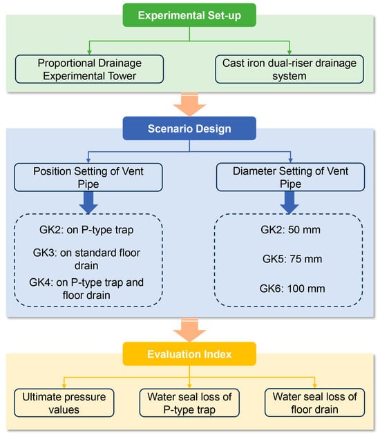
Figure 1.
Flowchart of this study.
2.1. Experimental Set-Up
The experiment was conducted at the National Drainage Pipe Technology Center—Shanxi Xuan’s proportional Drainage Experimental Tower. This facility comprises 19 floors, with a total height of 60 m and each floor measuring 3 m in height (see Figure 2). The 19th floor serves as the vent level, floors 14 to 18 function as water drainage levels, floors 2 to 13 are designated for testing, and the 1st floor houses the drainage outlet pipe.
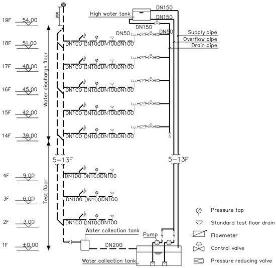
Figure 2.
Schematic diagram of the constant flow test system.
As shown in Figure 2, the experimental pipeline system consists of a cast iron dual-riser drainage configuration. The dedicated vent riser is indirectly connected to the drainage riser via an anti-backflow H-pipe. Horizontal drainage branch pipes on floors 2 through 18 are inclined toward the drainage riser at a gradient of 0.026 and connected using W-shaped tee-junctions (DN100 × 90° T). A large-curvature, variable cross-section reducer elbow is installed at the base of the drainage riser to connect with the bottom drainage pipe. Each test floor is equipped with a standard floor drain and a cast iron P-type trap (DN100) connected to the horizontal drainage branch pipe. All drainage pipes, vent pipes, and associated components were installed in accordance with current relevant standards [30,31].
The floor drain used in the experiment, as specified in references [32], was a fully transparent acrylic standard test floor drain with a water seal ratio of 0.95 and a water seal volume of 255.67 mL. Its surface was marked with scales to facilitate precise measurements, closely replicating parameters found in practical engineering applications and enabling repeatable referencing. The water seal depth in the floor drain could be directly measured visually with an accuracy of 1 mm. The P-type trap, constructed from cast iron, was equipped with an external glass tube water level gauge to indicate the internal water seal depth, also readable manually. Additionally, high-speed cameras were installed at both the standard floor drain and the P-type trap to monitor water seal conditions. These conditions were observed in real time through the measurement and control system located in the control room on the second floor of the experimental tower.
2.2. Experimental Procedure
The experimental procedure was primarily managed through the building drainage test system located in the control room on the second floor of the experimental tower. Each drainage floor was equipped with a booster pump to regulate the flow rate. The water release layers were configured to discharge a maximum flow rate of 2.5 L/s per floor, with incremental adjustments of ±0.5 L/s. The cumulative flow rate across the superimposed water release layers represented the maximum drainage capacity of the system under the tested conditions. Once the drainage flow rate stabilized at the designated test value, the experiment was conducted for 60 s. During this period, pressure and water seal data were recorded. Upon completion, the water seal loss was measured via on-site visual inspection. Pressure, flow rate, and water seal liquid level data were synchronously collected at 200-ms intervals, with pressure data recorded over the full 60-s duration, ensuring high accuracy of the test system data.
During the experiment, each scenario was conducted at least twice to meet the following criteria: the instantaneous pressure at the tested floor’s pressure measurement point was maintained within ±0.4 MPa, and the water seal loss in the standard floor drain was kept within 25 mm. The reported test results represent the average of three measurements under identical conditions. If the difference between any two measurements exceeded 10% of the smaller value, the system was retested until the specified requirements were satisfied.
2.3. Scenario Design
To address the objectives of this study, two independent experiments were designed to systematically investigate the maximum drainage capacity of dual-stack plumbing systems, focusing on the performance of vent and drainage systems under varying conditions. The first experiment examined the influence of different appliance installation positions, while the second explored the effects of varying pipe diameters. These experiments aimed to elucidate the optimal configurations for enhancing drainage efficiency and maintaining indoor environmental health, thereby providing evidence-based insights for improving vent pipe designs in dual-stack plumbing systems.
2.3.1. Position Setting of Vent Pipe
As presented in Table 1, four distinct experimental scenarios were designed to evaluate the performance of the dual-stack plumbing system under varying vent pipe configurations. Scenario GK1 represents a conventional cast iron dual-riser drainage system without dedicated appliance vent pipes. Scenario GK2 builds upon GK1 by incorporating a DN50 vent pipe connected to the P-type trap on the test floor. Scenario GK3 involves the installation of a dedicated appliance vent pipe on the standard floor drain. Scenario GK4 combines elements of GK2 and GK3 by equipping both the P-type trap and the standard floor drain with DN50 appliance vent pipes simultaneously. Additionally, the vertical drainage pipe and vent riser both have diameters of 100 mm, with the drainage riser extending to the vent level at the top of the experimental tower. The detailed test conditions for these scenarios are outlined in Table 1, while the corresponding system schematic diagrams are illustrated in Figure 3a–d.

Table 1.
Experimental scenarios for different position of vent pipe.
2.3.2. Diameter Setting of Vent Pipe
Table 2 presents the detailed design specifications for the additional scenarios. Scenario GK5 modifies the baseline configuration by increasing the diameter of the vent pipe connected to the P-type trap to DN75, while Scenario GK6 further enlarges the vent pipe diameter to DN100. These modifications aim to evaluate the impact of larger vent pipe diameters on the drainage performance and water seal stability in the dual-stack plumbing system, contributing to the optimization of vent configurations for enhanced indoor environmental health. The schematic diagrams illustrating the system configurations for GK5 and GK6 are provided in Figure 3e,f.
Table 2.
Experimental scenarios for different diameters of vent pipe.

Figure 3.
Schematic diagram of vent for appliances at different installation positions and with different diameters, (a) without dedicated appliance vent pipe, (b) DN50 vent pipe on P-type trap, (c) DN50 vent pipe on the standard floor drain, (d) vent pipes on P-type trap and floor drain, (e) DN75 vent pipe on P-type trap, and (f) DN100 vent pipe on P-type trap.
3. Results
3.1. Impact of Vent Pipe’s Existing on the Performance of Vent and Drainage
Under the GK1 configuration, where no appliance vent pipe was installed on the P-type trap of the drainage system, the measured maximum drainage flow rate was 6.5 L/s. In contrast, the GK2 scenario, which incorporated a DN50 appliance vent pipe on the horizontal branch pipe, achieved a maximum drainage flow rate of 7.5 L/s—an improvement of 1.0 L/s over GK1. Figure 4 illustrates the comparison of ultimate pressure values across the test floors for the scenarios of GK1 and GK2. As evident from the figure, in the GK1 configuration, the maximum positive pressures predominantly occur on the lower floors and remain below 200 Pa. Conversely, the maximum negative pressures are observed on the 10th and 12th floors. This distribution can be attributed to inadequate vent at the base of the system during drainage, which generates elevated positive pressures, coupled with restricted air intake at the top of the drainage riser, resulting in pronounced negative pressures. In addition, the GK1 scenario exhibits significant pressure fluctuations throughout the drainage system.
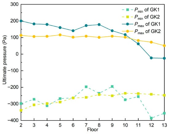
Figure 4.
The ultimate pressure values at the maximum drainage flow of GK1 and GK2.
Regarding the GK2 configuration, the pressure curves for both positive and negative pressures across the entire drainage system exhibit significantly smoother profiles compared to those observed in the GK1 scenario, with reduced overall pressure fluctuations. Specifically, positive pressures on the lower floors (2nd to 10th) are markedly decreased, stabilizing at approximately 100 Pa. Negative pressures on the higher floors are also substantially reduced; however, a notable negative pressure peak of approximately −350 Pa persists on the 2nd floor. These findings indicate that the incorporation of a DN50 appliance vent pipe at the P-type trap in the GK2 configuration enhances system vent, mitigates pressure fluctuations, and increases the maximum drainage capacity by 1.0 L/s compared to GK1. This improvement underscores the role of targeted vent pipe integration in optimizing hydraulic stability and water seal preservation.
Figure 5 and Figure 6 illustrate the water seal losses in the P-type trap and standard floor drain under the GK1 and GK2 configurations when the drainage system reaches its ultimate pressure values. The results demonstrate that, under the GK2 condition, water seal losses in both the P-type trap and floor drain are consistently lower across most floors compared to GK1, with reduced fluctuations. Notably, water seal loss on higher floors is significantly diminished in GK2. For instance, under the GK1 configuration, the P-type trap on the 13th floor exhibits a water seal loss of approximately 20 mm, whereas under GK2, this loss is reduced to about 10 mm—a decrease of roughly 50%.
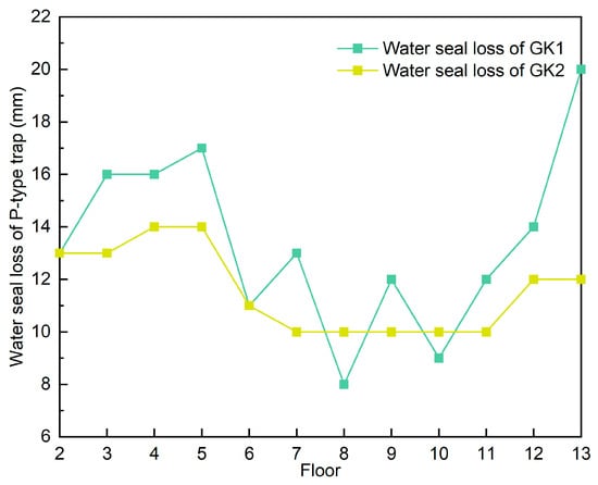
Figure 5.
Water seal loss of P-type trap at the maximum drainage flow of GK1 and GK2.
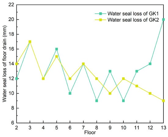
Figure 6.
Water seal loss of floor drain at the maximum drainage flow of GK1 and GK2.
Similarly, water seal losses on lower floors under GK2 are reduced by approximately 10% compared to GK1. This reduction is primarily attributed to the diminished suction effect caused by negative pressure, as evidenced by the significantly lower negative pressure on higher floors in GK2, as shown in Figure 4. Furthermore, the incorporation of a DN50 appliance vent pipe on the horizontal branch pipe in GK2 enhances vent, promoting smoother airflow and stabilizing internal pressures within the drainage system. This improved hydraulic stability plays a critical role in protecting the water seal integrity of sanitary fixtures.
3.2. Comparison of Vent Pipe’s Position on the Performance of Vent and Drainage
The experiments revealed that the maximum drainage flow rate across the GK2, GK3, and GK4 configurations was consistently 7.5 L/s. As shown in Figure 7, the maximum positive pressure in the GK3 configuration is significantly higher than that in GK2 and GK4, particularly on the lower floors. In contrast, the GK4 configuration exhibits the lowest maximum positive pressure among the three scenarios, while the positive pressure values for GK2 and GK4 are closely aligned. These results suggest that installing a DN50 appliance vent pipe at the P-type trap (GK2) has a more pronounced effect on reducing system pressure fluctuations compared to installing a vent pipe at the standard floor drain (GK3). Notably, the simultaneous installation of appliance vent pipes at both the P-type trap and the standard floor drain (GK4) yields minimal additional benefits over the GK2 configuration in terms of pressure stabilization. Across all three configurations, both maximum positive and negative pressure values decrease with increasing floor height. However, pressure values on the lower and higher floors exhibit minimal fluctuations and remain relatively stable. This stability is attributed to the enhanced vent performance of the system, which maintains a slight negative pressure state, thereby improving hydraulic balance and protecting water seal integrity in the dual-stack plumbing system.
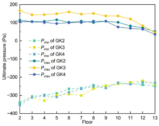
Figure 7.
The ultimate pressure values at the maximum drainage flow of GK2, GK3, and GK4.
Figure 8, Figure 9 and Figure 10 present the water seal losses for the P-type trap and standard floor drain under the GK2, GK3, and GK4 configurations of the dual-riser drainage system. The results indicate that the water seal loss at the P-type trap across most floors is lowest under the GK2 configuration compared to GK3 and GK4. Conversely, the GK3 configuration exhibits the highest water seal losses for both the P-type trap and the standard floor drain on most floors, while GK4 shows intermediate values between GK2 and GK3. These findings suggest that the placement of the appliance vent pipe significantly influences the water seal protection in the drainage system. Specifically, positioning the DN50 appliance vent pipe at the P-type trap (GK2) more effectively balances airflow dynamics, leading to reduced water seal losses and enhanced hydraulic stability. In contrast, placing the vent pipe at the standard floor drain (GK3) is less effective, and the combined placement at both the P-type trap and floor drain (GK4) offers only marginal improvements over GK2. Additionally, under identical conditions, the water seal loss in the standard floor drain is slightly higher than that in the P-type trap, likely due to differences in their internal structures, which influence airflow and pressure interactions. These observations underscore the importance of optimizing vent pipe placement to minimize water seal depletion, thereby reducing the risk of sewer gas intrusion and enhancing indoor environmental health in dual-stack plumbing systems.
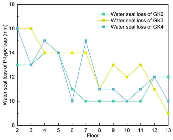
Figure 8.
Water seal loss of P-type trap at the maximum drainage flow of GK2, GK3, and GK4.
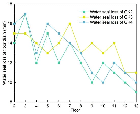
Figure 9.
Water seal loss of floor drain at the maximum drainage flow of GK2, GK3, and GK4.
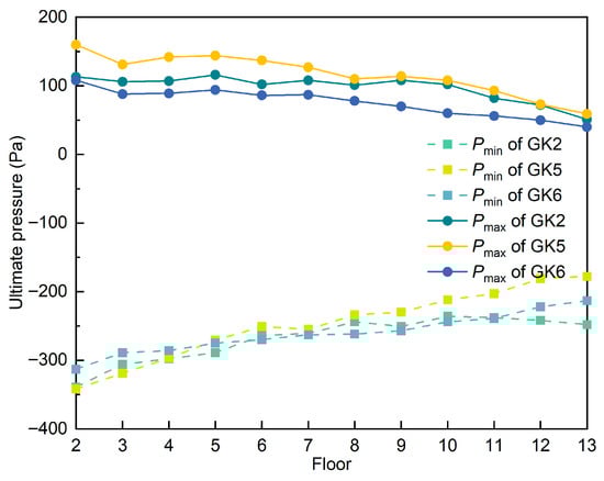
Figure 10.
The ultimate pressure values at the maximum drainage flow of GK2, GK5, and GK6.
3.3. Comparison of Vent Pipe’s Diameter on the Performance of Vent and Drainage
The maximum drainage flow rate of the dual-riser drainage system under both GK5 and GK6 configurations was measured at 7.5 L/s, consistent with the flow rate observed in the GK2 configuration. These results indicate that varying the diameter of the appliance vent pipe (DN50 in GK2, DN75 in GK5, and DN100 in GK6) has no significant impact on the system’s maximum drainage capacity. Figure 11 and Figure 12 presents a comparison of the pressure profiles across these configurations under ultimate pressure conditions. The inclusion of an appliance vent pipe in all three configurations balances airflow within the system, effectively mitigating pressure fluctuations and facilitating smoother drainage. Consequently, both positive and negative pressure fluctuations across the system are relatively subdued, promoting enhanced water seal protection. Specifically, the positive pressure in the GK2 configuration lies between that of GK5 and GK6. In GK5, the positive pressure on lower floors at the maximum flow rate approaches 170 Pa, whereas in GK6, positive pressures across all floors are the lowest, generally below 100 Pa. Conversely, GK5 exhibits the smallest negative pressure on higher floors, but its pressure curve displays the greatest variability, with the negative pressure on the second floor reaching approximately −400 Pa—the highest among the three configurations. These findings suggest that increasing the vent pipe diameter to DN75 or DN100 (GK5 and GK6) effectively reduces negative pressure on higher floors, while negative pressure values on other floors show minimal variation across the three configurations.
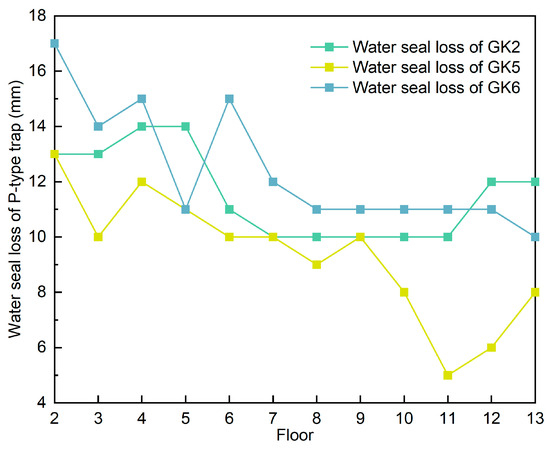
Figure 11.
Water seal loss of P-type trap at the maximum drainage flow of GK2, GK5, and GK6.
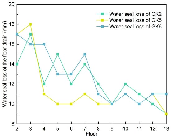
Figure 12.
Water seal loss of floor drain at the maximum drainage flow of GK2, GK5, and GK6.
The water seal losses of the P-type trap and floor drain at the maximum drainage flow of the drainage systems under the three working conditions of GK2, GK5 and GK6 are compared as shown in Figure 12 and Figure 13. As can be seen from Figure 12 and Figure 13, the water seal losses of the P-type trap and floor drain on most floors of GK2 are between those of GK5 and GK6. On the 10th to 14th floors, the P-type trap water seal loss under GK5 operation is significantly reduced. The main reason is that the water seal loss of sanitary ware is mainly due to the negative pressure suction effect. The maximum negative pressure value on the high floors of GK2 is the smallest among the three operation conditions, and the maximum negative pressure value on the high floors is all less than −300 Pa. However, the water seal loss values of some floors under GK6 condition are all greater than those of GK2 and GK5, indicating that the pipe diameter of the vent pipe of the appliance is not positively correlated with the water seal loss.
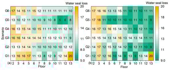
Figure 13.
Water seal loss of P-type trap and floor drain at the maximum drainage flow of GK1 to GK6, (a) water seal loss of P-type trap, and (b) water seal loss of floor drain.
Figure 11 and Figure 13 present a comparison of water seal losses for the P-type trap and floor drain at the maximum drainage flow rate of 7.5 L/s under the GK2, GK5, and GK6 configurations of the dual-riser drainage system. The results show that water seal losses for both the P-type trap and floor drain on most floors in the GK2 configuration (DN50 appliance vent pipe) are intermediate between those observed in GK5 (DN75) and GK6 (DN100). Notably, on the 10th to 14th floors, the water seal loss in the P-type trap under the GK5 configuration is significantly reduced compared to GK2 and GK6. This reduction is primarily attributed to the diminished negative pressure suction effect, as the maximum negative pressure on higher floors in GK5 is the lowest among the three configurations, with values consistently below −300 Pa. In contrast, water seal losses on several floors under the GK6 configuration exceed those in GK2 and GK5, indicating that increasing the appliance vent pipe diameter does not consistently correlate with reduced water seal loss.
4. Discussions
This study, through full-scale experiments, elucidates the critical influence of appliance vent pipe position and diameter on drainage performance and water seal integrity in high-rise dual-riser systems—issues directly linked to indoor environmental health. Positioning the DN50 appliance vent pipe at the P-type trap (GK2) proved optimal. It increased maximum drainage capacity from 6.5 L/s (baseline GK1, no appliance vent) to 7.5 L/s—a consistent 15.4% improvement—while simultaneously minimizing water seal losses across nearly all floors. Although peak drainage capacity remained 7.5 L/s regardless of vent location (GK2, GK3, GK4), water seal performance differed dramatically: on the 13th floor, P-type trap ventilation reduced seal loss from approximately 20 mm (GK1) to approximately 12 mm (GK2)—a 40% reduction. In contrast, floor-drain-only ventilation (GK3) yielded the highest losses on most floors, while combined ventilation (GK4) produced only intermediate values (typically 10–15 mm on upper floors), confirming the absence of synergistic benefit from multiple vent points (see Figure 13).
Mechanistically, the P-type trap’s proximity to the riser junction enables immediate neutralization of negative pressure transients induced by falling water columns, effectively suppressing siphonage at its source. Floor-drain vents, being farther along the branch, exhibit longer air-replenishment paths and poorer transient attenuation, resulting in sustained negative pressures (e.g., up to –352 Pa on lower floors in GK3 vs. –339 Pa in GK2). These findings explicitly demonstrate that targeted, single-point appliance ventilation at the P-type trap delivers the most efficient protection of terminal water seals, significantly outperforming traditional riser-focused strategies in preventing pathogen-laden aerosol ingress into occupied spaces.
In addition, the results from configurations with three appliance vent pipe diameters at the P-type trap (GK2: DN50; GK5: DN75; GK6: DN100) confirm that maximum drainage capacity remained constant at 7.5 L/s in all cases. Increasing the vent diameter beyond DN50 therefore provides no further gain in peak discharge, indicating a clear efficiency threshold for drainage capacity enhancement. More notably, the relationship between vent diameter and water seal loss is non-linear and strongly height-dependent. On higher floors (9th–13th), the DN75 configuration consistently exhibited the lowest water seal losses—typically 15–25% lower than DN50 and up to 30% lower than DN100—while maintaining negative pressures below –250 Pa. This superior performance on upper floors arises because airflow is relatively stable, allowing DN75 to deliver adequate replenishment at optimal velocity, effectively suppressing siphonage without inducing excessive turbulence.
On lower and middle floors, pressure dynamics are dominated by falling water columns and stronger entrainment effects. Here, DN100 reduced peak positive pressures most effectively; however, the resulting high air ingress occasionally amplified internal flow disturbances, leading to paradoxically higher water seal losses on certain floors compared with DN75.
These findings reveal that no single diameter is universally optimal. Instead, diameter selection should be zone-specific: DN75 is recommended as the preferred choice for upper floors, whereas middle- and lower-floors branches may benefit from site-specific pressure testing to determine whether DN75 or DN100 achieves the best balance between positive-pressure suppression and disturbance minimization.
This study has several limitations. First, the experiments were conducted under constant-flow conditions, yielding no data on pipeline flow dynamics under transient flow scenarios. In practical applications, however, steady-state and instantaneous flows often coexist, potentially influencing system performance. Future research should incorporate full-scale experiments integrating multiple drainage regimes to address this gap. Second, the experimental pipeline was constructed from cast iron, which may exhibit different vibrational responses compared to plastic alternatives. Pipe wall vibrations in plastic systems could exacerbate water seal losses, necessitating supplementary comparative tests across diverse materials. Finally, the experimental tower featured uniform floor heights of 3 m and consistent horizontal branch pipe slopes. In real-world buildings, variable floor heights and pipeline layouts can alter aerodynamic characteristics, affecting pressure distribution and drainage efficiency. Subsequent investigations could employ models with adjustable floor heights and slopes or integrate computational fluid dynamics (CFD) simulations to replicate such complexities.
5. Conclusions
This study utilized a full-scale proportional drainage experimental tower to evaluate the efficacy of appliance vent pipes installed on horizontal drainage branches as a comprehensive strategy for water seal protection in dual-riser systems. Maximum drainage capacities were determined under varying appliance vent pipe positions and diameters, complemented by quantitative analyses of pressure transients and water seal losses within the drainage network. Several conclusions can be addressed:
- (1)
- Incorporating an appliance vent pipe on the horizontal drainage branch effectively enhances the system’s maximum drainage capacity, albeit with limited incremental gains. Compared to the baseline conventional cast iron dual-riser drainage system (6.5 L/s), configurations with appliance vent pipes (GK2–GK6) achieve 7.5 L/s—an improvement of 1.0 L/s.
- (2)
- Appliance vent pipe position exerts no influence on maximum drainage capacity, which remains consistent at 7.5 L/s across all configurations (GK2–GK4). However, position significantly affects water seal losses: the P-type trap placement (GK2) yields the lowest losses on most floors, the combined P-type trap and standard floor drain placement (GK4) produces intermediate losses, and the standard floor drain placement (GK3) results in the highest losses. The P-type trap is the optimal position for appliance vent pipe installation on horizontal branches.
- (3)
- Appliance vent pipe diameter has no discernible effect on maximum drainage capacity, which is uniformly 7.5 L/s across configurations (GK2, GK5, GK6). Moreover, increasing the appliance vent pipe diameter does not consistently correlate with reduced water seal loss.
- (4)
- Appliance vent pipes on horizontal drainage branches effectively attenuate maximum positive and negative pressure fluctuations across floors, thereby reducing water seal losses in sanitary fixtures. Among diameters of DN50, DN75, and DN100, the DN75 configuration (GK5) minimizes water seal losses on most floors, offering superior protection and serving as a practical recommendation for engineering applications.
- (5)
- In high-rise building engineering practice, appliance vent pipe design should adopt a height-zoned approach tailored to anticipated drainage loads and pressure characteristics. DN75 is adopted as the standard diameter of the ventilation pipe in the high zone, while targeted optimization is carried out in the low and middle zones where the drainage load is concentrated or the pressure fluctuates greatly.
Author Contributions
Conceptualization, Q.S. and S.L.; methodology, Q.S.; writing—original draft preparation, Q.S. and H.M.; writing—review and editing, Q.S. and S.L.; visualization, Q.S. and H.M.; supervision, D.L. and S.L.; funding acquisition, S.L. All authors have read and agreed to the published version of the manuscript.
Funding
This research was funded by the Fujian Province Young and Middle-Aged Teacher Education Research Project (No. JAT241225).
Data Availability Statement
The original contributions presented in this study are included in the article. Further inquiries can be directed to the corresponding author.
Conflicts of Interest
The authors declare no conflicts of interest.
References
- Klepeis, N.E.; Nelson, W.C.; Ott, W.R.; Robinson, J.P.; Tsang, A.M.; Switzer, P.; Behar, J.V.; Hern, S.C.; Engelmann, W.H. The National Human Activity Pattern Survey (NHAPS): A resource for assessing exposure to environmental pollutants. J. Expo. Sci. Environ. Epidemiol. 2001, 11, 231–252. [Google Scholar] [CrossRef] [PubMed]
- Sharif, K.; Gormley, M. Integrating the Design of Tall Building, Wastewater Drainage Systems into the Public Sewer Network: A Review of the Current State of the Art. Water 2021, 13, 3242. [Google Scholar] [CrossRef]
- Gormley, M.; Mohammed, S.; Kelly, D.A.; Campbell, D.P. Application and Validation of AIRNET in Simulating Building Drainage Systems for Tall Buildings. Buildings 2025, 15, 1725. [Google Scholar] [CrossRef]
- Gormley, M.; Kelly, D.; Campbell, D.; Xue, Y.; Stewart, C. Building Drainage System Design for Tall Buildings: Current Limitations and Public Health Implications. Buildings 2021, 11, 70. [Google Scholar] [CrossRef]
- Mahapatra, I.; Gormley, M. Artificial neural network modelling for predicting classical air pressure profile curves in building drainage systems. Build. Serv. Eng. Res. Technol. 2023, 44, 423–441. [Google Scholar] [CrossRef]
- Gormley, M.; Swaffield, J.A.; Sleigh, P.A.; Noakes, C.J. An assessment of, and response to, potential cross-contamination routes due to defective appliance water trap seals in building drainage systems. Build. Serv. Eng. Res. Technol. 2012, 33, 203–222. [Google Scholar] [CrossRef]
- SARS Expert Committee. Extract from SARS in Hong Kong: From Experience to Action. Aust. Health Rev. A Publ. Aust. Hosp. Assoc. 2003, 26, 22–25. [Google Scholar]
- Hung, H.C.K.; Chan, D.W.T.; Law, L.K.C.; Chan, E.H.W.; Wong, E.S.W. Industrial experience and research into the causes of SARS virus transmission in a high-rise residential housing estate in Hong Kong. Build. Serv. Eng. Res. Technol. 2006, 27, 91–102. [Google Scholar] [CrossRef]
- Kang, M.; Wei, J.; Yuan, J.; Guo, J.; Zhang, Y.; Hang, J.; Qu, Y.; Qian, H.; Zhuang, Y.; Chen, X.; et al. Probable Evidence of Fecal Aerosol Transmission of SARS-CoV-2 in a High-Rise Building. Ann. Intern. Med. 2020, 173, 974–980. [Google Scholar] [CrossRef]
- Qiu, S.; Xiao, D.; Zhang, X.; Wang, S.; Wang, T.; Li, X.; Xu, M. Experimental investigations of the phase change impacts on flash boiling spray propagations and impingements. Fuel 2022, 312, 122871. [Google Scholar] [CrossRef]
- Jiang, X.; Zhao, C.; Chen, Y.; Gao, X.; Zhang, Q.; Chen, Z.; Li, C.; Zhao, X.; Liu, Z.; Huang, W.; et al. Probable Evidence of Aerosol Transmission of SARS-CoV-2 in a COVID-19 Outbreak of a High-Rise Building. Environ. Health Insights 2023, 17, 11786302231188269. [Google Scholar] [CrossRef]
- Wang, Q.; Lin, Z.; Niu, J.; Choi, G.K.-Y.; Fung, J.C.H.; Lau, A.K.H.; Louie, P.; Leung, K.K.M.; Huang, J.; Cheng, P.; et al. Spread of SARS-CoV-2 aerosols via two connected drainage stacks in a high-rise housing outbreak of COVID-19. J. Hazard. Mater. 2022, 430, 128475. [Google Scholar] [CrossRef]
- Gormley, M.; Kelly, D.A. Pressure transient suppression in drainage systems of tall buildings. Build. Res. Inf. 2019, 47, 421–436. [Google Scholar] [CrossRef]
- Gormley, M.; Kelly, D. Propagation of bioaerosols from the building drainage system; cross-transmission, detection and prevention. In Proceedings of the 39th International Symposium CIB W062 on Water Supply and Drainage for Buildings 2013, Nagano, Japan, 17–20 September 2013. [Google Scholar]
- Jack, L.; Cheng, C.; Lu, W. Numerical simulation of pressure and airflow response of building drainage ventilation systems. Build. Serv. Eng. Res. Technol. 2006, 27, 141–152. [Google Scholar] [CrossRef]
- Zhang, Y.; Wang, Y.; Wang, F.; Xu, X.; Wu, X. Numerical investigation on the transmission and dispersion of aerosols in a 7-stories building drainage system. Build. Environ. 2021, 201, 108009. [Google Scholar] [CrossRef] [PubMed]
- Swaffield, J.A.; Jack, L.B.; Campbell, D.P. Control and suppression of air pressure transients in building drainage and vent systems. Build. Environ. 2004, 39, 783–794. [Google Scholar] [CrossRef]
- Wong, E.S.W.; Li, Y.-L.; Zhu, Z.-J. Predicting air pressure in drainage stack of high-rise building. Appl. Math. Mech.-Engl. Ed. 2013, 34, 351–362. [Google Scholar] [CrossRef]
- Guan, Y.; Yan, X.; Fang, Z.; Ren, S. Mathematical model and experiment analysis of pressure fluctuation inside dual-stack drainage system in residential buildings. Water Sci. Technol. 2022, 85, 3145–3158. [Google Scholar] [CrossRef] [PubMed]
- Cheng, C.L.; Mui, K.W.; Wong, L.T.; Yen, C.J.; He, K.C. Characteristics of air pressure fluctuations in high-rise drainage stacks. Build. Environ. 2010, 45, 684–690. [Google Scholar] [CrossRef]
- Yu, T.; Ding, Q.; Wang, L.; Zhu, D.Z.; Shao, Y. Experimental study on air pressure variation in a horizontal pipe of single-stack drainage system. Water Sci. Technol. 2019, 79, 114–125. [Google Scholar] [CrossRef] [PubMed]
- Yan, X.; Guan, Y.; Fang, Z.; Ren, S.; Yin, H. Influence of Bottom Connection on Capacity of Secondary Vent Riser in Building Drainage System. China Water Wastewater 2024, 40, 62–67. [Google Scholar]
- Chen, R.; Yan, X.; Shang, Y.; Guan, Y.; Fang, Z. The influence of different offset modes on the drainage characteristics of a double stack drainage system in a high-rise building. Build. Serv. Eng. Res. Technol. 2023, 44, 443–458. [Google Scholar] [CrossRef]
- Guo, Y.; Yan, X.; Shang, Y.; Guan, Y.; Fang, Z. Influence of Offset Terminal Elbow Shape on the Discharge Capacity of a High-Rise Building Drainage System. J. Pipeline Syst. Eng. Pract. 2023, 14, 04023028. [Google Scholar] [CrossRef]
- Guan, Y.; Yin, H.; Ren, S.; Wu, K.; Fang, Z. Influence of Installing Offset Pipe on Water Flow Capacity of Drainage System. China Water Wastewater 2024, 40, 67–72. [Google Scholar]
- Guan, Y.; Fang, Z.; Yuan, J.; Tang, Z. Influence of installation of S-shaped pipe offset on the water flow capacity of double stack drainage system in a high-rise building. Build. Serv. Eng. Res. Technol. 2020, 41, 603–622. [Google Scholar] [CrossRef]
- Li, Q.; Yan, X.; Shang, Y.; Guan, Y.; Fang, Z. Overcoming the influence of a 2 metre long pipe offset on water flow capacity of drainage with secondary ventilation in a high-rise building. Build. Serv. Eng. Res. Technol. 2022, 43, 741–753. [Google Scholar] [CrossRef]
- Li, Z. Risk prevention and control and technical measures for building water system in response to COVID-19. Water Wastewater Eng. 2020, 56, 49–53. [Google Scholar] [CrossRef]
- Yin, H.; Guan, Y.; Ren, S.; Wu, K.; Fang, Z. Influence of Vent Pipe Diameter on Water Capacity of Drainage System with Auxiliary Vent Pipe. China Water Wastewater 2021, 37, 40–45. [Google Scholar]
- GB 50242-2002; Code for Acceptance of Construction Quality of Building Water Supply, Drainage and Heating Engineering. National Standards of China: Beijing, China, 2002.
- GB/T 12772-2016; Flexible Interface Cast Iron Pipes, Fittings and Accessories for Drainage. National Standards of China: Beijing, China, 2016.
- GB/T 27710-2020; Floor Drain. National Standards of China: Beijing, China, 2020.
Disclaimer/Publisher’s Note: The statements, opinions and data contained in all publications are solely those of the individual author(s) and contributor(s) and not of MDPI and/or the editor(s). MDPI and/or the editor(s) disclaim responsibility for any injury to people or property resulting from any ideas, methods, instructions or products referred to in the content. |
© 2025 by the authors. Licensee MDPI, Basel, Switzerland. This article is an open access article distributed under the terms and conditions of the Creative Commons Attribution (CC BY) license (https://creativecommons.org/licenses/by/4.0/).