Abstract
This study investigates the impact of steel slag coarse aggregate (SSA) particle size on the macroscopic mechanical properties of concrete. Considering that the macroscopic behavior of concrete is significantly influenced by its mesoscale structural characteristics, and that coarse aggregate particle size is a key factor determining these features, uniaxial compression experiments together with mesoscale simulations were carried out to develop a model linking the mesoscale structure to the mechanical response of steel slag coarse aggregate concrete (SSAC). The results show that SSAC exhibits a failure pattern comparable to that of natural aggregate concrete (NAC), but its stress–strain curve exhibits a steeper ascending branch and higher peak stress. With the increasing SSA replacement ratio, the peak stress continuously increases; within the same particle size range, the elastic modulus shows an initial increase followed by a subsequent decrease, reaching its maximum at a 50% replacement ratio. Expanding the particle size range changes the peak strain response from approximately linear to rapidly increasing; smaller particle sizes result in a gentler post-peak drop, whereas higher replacement ratios produce a steeper decline. The mesoscale model further shows that for SSA particle sizes of 5–20 mm, 5–15 mm, and 5–10 mm, the cohesive strength of the interfacial transition zone (ITZ) increases by 75%, 106%, and 92%, respectively, compared with NAC. Increasing the coarse aggregate volume fraction further enhances the ITZ strength improvement. This study offers valuable insights for improving the mixture design and performance of SSAC.
1. Introduction
Steel slag is a significant solid by-product formed during crude steel manufacturing, with an annual output in China reaching several million tons [1]. To mitigate the land occupation and environmental pollution caused by steel slag stockpiling, its resource utilization has become a research focus both domestically and internationally [2]. Among the various approaches, partially or fully replacing natural coarse aggregates (NA) with SSA to produce steel slag coarse aggregate concrete (SSAC) is considered a typical method for realizing the high-value utilization of steel slag [3]. This method not only helps to reduce the overexploitation of natural aggregates and lower carbon emissions but also achieves a balance between economic and environmental benefits while ensuring structural load-bearing capacity and performance stability. Therefore, the application of SSA provides an important engineering pathway for the reduction and recycling of steel industry solid waste, with significant environmental and social value.
Concrete is one of the most extensively applied composite materials in engineering, primarily composed of cement, water, and aggregates, aggregates make up nearly 75% of the concrete volume, with coarse aggregates representing about 45% of that portion [4]. Therefore, the physical and mechanical characteristics of coarse aggregates largely determine the durability and mechanical performance of concrete. Previous research indicates that the macroscopic behavior of concrete is strongly influenced by various properties of coarse aggregates, including their mineral composition, surface area characteristics, morphology, stiffness, toughness, strength, gradation, and water absorption [5,6,7,8,9]. Moreover, the particle size of aggregates is a key factor in both the workability of fresh concrete and the mechanical behavior of hardened concrete.
Previous research has reported that increasing the aggregate size from 10 mm to 64 mm can lead to roughly a 10% reduction in concrete compressive strength, while the flexural strength changes relatively little [10]. Aïtcin [11] concluded that enlarging the aggregate particle size to 25 mm can improve the workability of concrete, but it may lead to the formation of larger and more heterogeneous ITZ, potentially weakening the overall performance of concrete. In contrast, Vu [12] found that under unconfined compression conditions, the compressive strength of concrete exhibits a slight increase as the coarse aggregate particle size increases. Ghorbani et al. [13] reported that for recycled aggregate concrete at the same replacement ratio, reducing the maximum aggregate size slightly improves the concrete’s strength and durability. Ezeldin and Aïtcin [14] suggested that for normal-strength concrete, factors like the type and particle size of coarse aggregates have a relatively limited effect on mechanical performance. In summary, the effect of coarse aggregate size on concrete performance is still not fully clarified. Most of the aforementioned studies use discrete aggregate size ranges as experimental variables, which only represent a single size interval and fail to capture the overall particle size distribution encountered in practical engineering applications. Therefore, improving the continuity and representativeness of aggregate size classification is essential for accurately evaluating the mechanical performance of concrete.
With the deepening of research, scholars have gradually shifted their focus from the material availability of steel slag to its effects on the mechanical performance and mesostructural homogeneity of concrete. At the macro scale, the incorporation of SSA significantly alters the strength, deformation, and crack resistance of concrete [15,16,17], which are jointly influenced by multiple factors, including aggregate particle size, replacement ratio, and spatial distribution. These macroscopic performance differences originate from the evolution of the internal mesostructure, including the characteristics of the ITZ between cement paste and SSA, pore distribution, and microcrack development patterns [18]. Studies have shown that the size, shape, and surface features of coarse aggregates influence the thickness and compactness of the ITZ, which in turn governs stress transmission and damage evolution [19,20]. At the microscopic level, the gradation of coarse aggregates strongly influences the development and spatial distribution of ITZs in hardened concrete, which in turn influences the microstructure and mechanical behavior of the material [21,22]. A higher proportion of large aggregates contributes to the formation of a skeleton effect, whereas a higher proportion of small aggregates promotes the development of a denser hardened matrix [23]. Overall, reasonably balancing the distribution of different aggregate sizes not only optimizes stress transfer paths and suppresses microcrack propagation but also enhances the mechanical performance and structural durability of concrete. Therefore, systematically analyzing the effects of different SSA particle size ranges and replacement ratios on concrete’s mechanical response and mesostructural damage evolution from a multi-scale perspective is of great significance for elucidating the reinforcement mechanisms of SSA.
Existing research on steel slag aggregates has mainly focused on their physicochemical properties and geometric characteristics. Regarding physicochemical properties, scholars have systematically analyzed the effects of active components such as CaO and SiO2 on potential hydration activity and expansion behavior [24]. In terms of geometry, studies have shown that the high angularity and rough surface of steel slag aggregates enhance interfacial bonding, thereby improving macroscopic mechanical performance [25]. Based on these findings, some studies have attempted to further improve SSA performance through the combined incorporation of slag, silica fume, or alkali residues [26,27,28].
However, compared with physicochemical modifications, systematic studies on the coupled effects of SSA particle size range and replacement ratio remain limited. Although some literature has addressed the influence of particle size, these studies generally suffer from single-dimensional analyses, discrete experimental designs, and insufficient mechanism explanations. Bian et al. [29] reported that compressive strength exhibits a nonlinear dependence on the maximum aggregate size but did not clarify the underlying physical mechanisms. Ren et al. [30] investigated the uniaxial compressive performance of SSA concrete with 5–20 mm particle size but did not refine the particle size range. Ukpata et al. [31] only examined discrete particle size samples without systematic verification. Therefore, although macroscopic experiments reveal the presence of particle size effects, the underlying mesostructural mechanisms still require further investigation.
From a mesoscale viewpoint, concrete is an extremely heterogeneous composite material, and its mechanical performance largely depends on the content, particle size, and spatial distribution of coarse aggregates [32]. The effect of aggregate particle size significantly influences stress transfer and crack propagation in concrete by altering the geometry of the ITZ and the cooperative deformation capacity between aggregates and the cement matrix. Hillerborg [33] reported that the fracture energy of concrete increases with the maximum aggregate size (MAS), while Rao and Prasad [34] found that the tensile strength and fracture toughness of high-strength concrete also improve as MAS increases. Zhuo and Ren [30,35] further showed through mesoscale simulations that variations in randomly distributed aggregate sizes influence the instability of crack propagation paths, which in turn affects the axial compressive strength and deformation behavior of concrete. However, existing studies mostly focus on single indicators such as strength or fracture energy, and a systematic understanding of how variations in SSA particle size range affect the complete stress–strain curve of concrete—particularly the post-peak softening stage and damage evolution—remains lacking.
Considering the strong randomness of concrete’s mesostructure, relying solely on macroscopic experiments requires a large number of specimens, incurs high costs, and cannot fully reveal the underlying failure mechanisms. Numerical simulation methods, which are not affected by experimental conditions or external environments, can partially replace or complement such material tests. Therefore, developing a suitable mesoscale mechanical model for concrete and clarifying the relationship between its mesostructure and macroscopic performance is of critical importance. Currently, multiphase mesoscopic models have become essential tools in concrete research, including lattice models [36,37,38], M–H models [39], stochastic mechanical performance models, and random aggregate models. Previous studies indicate that Lattice and M–H models are effective in capturing the tensile response of quasi-brittle materials such as concrete, but they inadequately describe the deformation behavior under compressive loading. Among these approaches, random aggregate models, due to their high adaptability in representing aggregate morphology and reconstructing mesostructure, have been widely used to simulate the heterogeneous characteristics of concrete. Chen et al. [40,41] employed an aggregate model based on random distribution to conduct numerical uniaxial compression experiments on recycled concrete, indicating that the regions of damage diffusion corresponded well with the CT scan observations, providing a more comprehensive validation of the internal structural softening of concrete.
To address the insufficient understanding of the coupled effects of SSA particle size range and replacement ratio in existing studies, this study aims to systematically examine the influence of steel slag coarse aggregates regarding the mechanical properties of concrete and the mesostructural reinforcement mechanisms at the macroscopic and mesoscopic scales. By combining experimental testing and numerical simulation, uniaxial compression tests were first conducted on concrete with SSA particle size ranges of 5–20 mm, 5–15 mm, and 5–10 mm and replacement ratios of 0%, 50%, and 100%, systematically analyzing the effects of different SSA particle size ranges and replacement ratios on the stress–strain behavior of SSAC under uniaxial compression. According to the experimental data, a random aggregate distribution was generated via the Monte Carlo method, and the three-dimensional arrangement of coarse aggregates was projected onto a two-dimensional plane using the Walraven formula to construct a stochastic aggregate model of SSAC. Subsequently, the uniaxial compression process was numerically simulated in ABAQUS 2020, and the model parameters were calibrated and determined according to the experimental results. On this basis, the effect of aggregate volume fraction on the reinforcing behavior of SSA on the mechanical performance of SSAC was further analyzed.
2. Materials and Methods
2.1. Experimental Test Details
2.1.1. Materials
Ordinary Portland cement (P.O. 42.5) supplied by Xinjiang Tianshan Cement Co., Ltd., Urumqi, China, was used in the experiment. The 28-day compressive and flexural strengths were evaluated in accordance with the “General Purpose Portland Cement” standard (GB175-2023) [42], yielding values of 48 MPa and 7.1 MPa, respectively. Additionally, the cement met the requirements for water consistency, setting time, and stability as specified in GB/T 1346-2024 [43], and its stability was confirmed to be satisfactory.
The NA used in the experiment were mechanically crushed limestone from local quarries in Xinjiang He feng Mining Co., Ltd., Xinjiang, China. The steel slag was supplied by Xinjiang Baogang Group Bayi Iron & Steel Plant, Xinjiang, China, generated during the oxygen converter steelmaking process and hydrated using the hot-stored method to accelerate expansion, with on-site stockpiling for approximately three years. Both the NA and steel slag aggregates had particle size ranges of 5–20 mm, and the test results according to the standard GB/T 14685-2011 “Gravel and Crushed Stone for Construction” [44] are presented in Table 1. The primary chemical composition of the steel slag listed in Table 2 was analyzed using X-ray fluorescence (XRF), while the free-CaO (f-CaO) content was determined via EDTA titration following the Chinese standard YB/T 4328-2012 [45]. The mineralogical composition of steel slag was characterized using X-ray diffraction (XRD). As shown in Figure 1, the steel slag primarily consists of C2F, C2S, C3S, and RO phases. Furthermore, a quantitative analysis of these crystalline phases was performed using the Rietveld method implemented in GSAS-II, and the relative mass fractions of the identified phases are summarized in Table 3. The fineness modulus of the natural sand, with a particle size range of 0–4.75 mm, was 2.68, classifying it as medium sand in Zone II. The particle size distributions of NA, SSA, and natural sand are presented in Figure 2.

Table 1.
Test Results of Steel Slag Aggregate Properties.
Table 2.
Chemical Composition of Steel Slag.
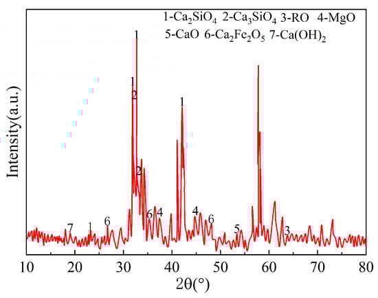
Figure 1.
XRD analysis of coarse steel slag.
Table 3.
Steel slag mineral phases composition.
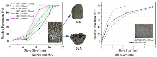
Figure 2.
Aggregate particle size distribution.
2.1.2. Mix Proportion Design and Specimen Preparation
Table 4 provides the detailed mix designs of the concrete, with a target strength grade of C40. The coarse aggregates were replaced using a volume-equivalent method, preparing concretes with SSA at three particle size ranges (5–10 mm, 5–15 mm, and 5–20 mm) and three replacement ratios (0%, 50%, and 100%). The water-reducing agent used in this study was a liquid polycarboxylate-based superplasticizer supplied by Huize Chemical, Shijiazhuang, China, with a solid content of approximately 32%. Its water content was included in the total mixing water listed in Table 4. This superplasticizer was employed to improve the workability of concrete, providing a water-reduction rate of up to 20%. During trial mixing, the dosage was adjusted to achieve a slump of 185 ± 10 mm. For each concrete mix, three prismatic specimens with dimensions of 150 × 150 × 300 mm were prepared for uniaxial compression tests, cast for 24 h, and then subjected to standard 28-day curing.
Table 4.
Concrete Mix Proportions.
Mortar compressive strength tests were performed according to JGJ/T 70–2009 “Standard for Basic Performance Test Methods of Construction Mortar” [46], with three specimens prepared for each mix. The compressive strength values obtained from these tests were used to determine the mechanical parameters of the mortar in the numerical model, providing fundamental input data for subsequent simulations.
2.1.3. Experimental Setup
A total of nine groups of specimens were subjected to uniaxial stress–strain tests. The experiments were conducted on an electro-hydraulic servo multifunctional structural testing system (YAW-15000F) with a maximum load capacity of 15,000 kN, meeting the Grade 1 accuracy requirements of GB/T 16825.1-2008 [47], and a maximum displacement of 500 mm. The loading rate was controlled at 0.2 mm/min (see Figure 3a). Before testing, the specimen surfaces were cleaned of moisture and debris, and a thin layer of white matte paint was evenly applied. After complete drying, random speckle patterns were drawn with a black marker to satisfy the requirements of digital image correlation (DIC) analysis; a typical random speckle pattern is shown in Figure 3b. The compression tests were conducted in accordance with GB/T 50081-2019 “Standard for Test Methods of Physical and Mechanical Properties of Concrete” [48]. To ensure accurate data acquisition, a UV supplementary light source was used during testing (see Figure 3c). Strain field data were synchronously captured via the DIC system, following methods consistent with those reported by Shaik [49] and Munoz [5]. The speckle images recorded by industrial cameras were analyzed using DIC-3D software (Digital Image Correlation) to obtain the stress–strain curve information.
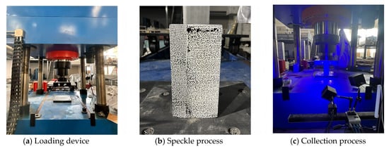
Figure 3.
Details of the experimental setup.
2.2. Mesoscopic Model of Steel Slag Coarse Aggregate Concrete and Its Constitutive Relationship
2.2.1. Mesoscopic Model Establishment
A two-dimensional mesoscopic concrete model with varying SSA particle size ranges and replacement ratios was established in this study. At the mesoscopic scale, concrete was considered as a heterogeneous composite material composed of a mortar matrix, coarse aggregates, and the ITZ between them. To balance model fidelity and computational efficiency, aggregates smaller than 5 mm were treated as part of the mortar matrix, while aggregates with sizes between 5 mm and 20 mm were regarded as coarse aggregates. Irregular polygonal particles with random distributions were employed to simulate their geometrical shapes, providing a more realistic representation of the concrete’s actual mesostructure. Figure 4 illustrates the mesostructural schematic of each component, distinguished by different colors.
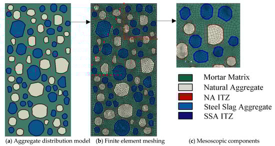
Figure 4.
Mesostructural model of SSAC.
Regarding the modeling of the ITZ, previous experimental studies have shown that its actual thickness typically ranges from 10 to 50 um [50,51]. However, directly modeling the ITZ at this scale would result in a dramatic increase in the number of elements, severely affecting computational efficiency. Considering that existing literature indicates that varying the ITZ thickness within 0.5–2 mm has a negligible effect on the macroscopic mechanical behavior of concrete [52], the ITZ thickness in this study was set to 1 mm, balancing both computational convergence and model rationality.
The study is based on the Monte Carlo random algorithm to construct a heterogeneous mesoscopic model of SSAC, with secondary development implemented in Python 3.13 to realize randomized generation of aggregate geometry, size, and interfacial properties. The specific procedure is as follows: (a) the continuous particle size distribution of 5–20 mm coarse aggregates was determined according to the Fuller grading curve and converted to a two-dimensional plane using the Walraven method, and then divided into three ranges (5–10 mm, 10–15 mm, and 15–20 mm) to satisfy maximum packing density under the specified volume fraction, allowing calculation of the number of particles in each size range; (b) pseudo-random numbers were then used within the two-dimensional modeling domain to generate initial aggregate vectors (particle size, centroid coordinates, etc.) according to the above grading, and during placement, area-based checks and minimum spacing criteria were applied to prevent particle overlap; (c) after arranging the circular aggregates, the particles were polygonized and an ITZ was extruded around them, ultimately forming a two-dimensional five-phase composite model comprising natural aggregates and their ITZ, cement mortar, and SSA and their ITZ; (d) the generated geometric model was subsequently imported into ABAQUS for pre-processing steps, including material assignment, interface definition, and meshing. The Fuller and Walraven formulas are presented in Equations (1) and (2), respectively.
where is the volume fraction of aggregates in the specimen, represents the particle size of each grade, and is the maximum aggregate size. The Fuller grading curve is applicable to three-dimensional models. For two-dimensional aggregate models, the Fuller curve is generally converted to a two-dimensional state using the Walraven plane conversion formula. The theoretical formulas are as follows:
where
is the volume fraction of coarse aggregates in the concrete specimen, which is 0.5. All other terms are the same as in Equations (1) and (2). Based on Equations (1) and (2), the coarse aggregate in steel slag concrete was assigned a particle size range of 5–20 mm, divided into three levels: 5–10 mm, 10–15 mm, and 15–20 mm.
2.2.2. Constitutive Model of Steel Slag Coarse Aggregate Concrete
In ABAQUS, there are various damage models applicable to brittle materials, among which the Concrete Damaged Plasticity Model (CDPM) is the most comprehensive. This model is based on the theory proposed by Lubliner et al. [53] and was further improved by Fenves and Lee et al. to incorporate enhanced criteria accounting for localized behavior. CDPM attributes the failure modes of brittle materials to two primary mechanisms: tensile cracking and compressive crushing. The yield surface is defined by two hardening parameters: the equivalent plastic tensile strain () and the equivalent plastic compressive strain (). Under uniaxial tension and compression loading, the material exhibits significant nonlinear evolution in its stress–strain response. The stress–strain relationships can be expressed as Equations (3) and (4).
In the equations, represents the tensile stress; is the tensile damage parameter, with 0 indicating no damage and 1 indicating complete damage; is the initial elastic modulus; is the tensile strain; is the plastic tensile strain; represents the compressive stress; is the compressive damage parameter, with 0 indicating no damage and 1 indicating complete damage; is the compressive strain; and is the plastic compressive strain.
In the CDP model, the post-peak softening behavior of the stress–strain curve is characterized by the cracking strain () and the inelastic compressive strain (). Therefore, in Equations (5) and (6), the cracking strain and the inelastic compressive strain are converted into the equivalent plastic tensile and compressive strains.
This study assumes that concrete failure is primarily due to the damage of the mortar matrix and the ITZ, while the aggregates do not develop through-cracks under uniaxial compression; therefore, coarse aggregates are modeled as linearly elastic in the meso-scale model. Both NA and SSA are enveloped by a layer of cement mortar, and the mechanical behavior of their interfacial transition zones resembles that of concrete. In addition, the surface of steel slag is relatively rough and exhibits certain hydration activity, so the mechanical performance of its ITZ is stronger than that of natural aggregates. The tensile-to-compressive strength ratio of mortar and ITZ is 0.1. Consequently, the mortar matrix and ITZ are represented using the CDPM. Under uniaxial compression, the material behaves elastically until the initial stress is reached; between the yield stress and ultimate stress, hardening occurs; beyond the ultimate stress, softening takes place. The constitutive relationship is illustrated in Figure 5.
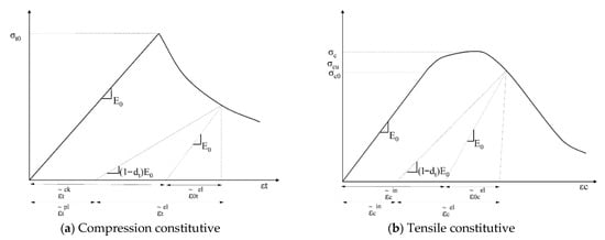
Figure 5.
Plastic damage constitutive relationship.
3. Results and Discussion
3.1. Experimental Results
3.1.1. Failure Modes of Steel Slag Coarse Aggregate Concrete
Observations from the uniaxial compression tests indicate that the failure process of normal concrete and SSAC exhibits similar macroscopic stages; however, the crack development patterns and ultimate failure modes show significant differences due to variations in coarse aggregate particle size and replacement ratio. The specific failure processes and characteristics are as follows:
As illustrated in Figure 6, the failure process of normal concrete and steel slag concrete is similar [54]. Before reaching 70% of the ultimate load, the initial loading stage under uniaxial compression corresponds to the elastic stage, during which the stress and strain of the specimen increase approximately proportionally. On one hand, microcracks inside the specimen begin to propagate; on the other hand, some microcracks are compressed and closed, causing the internal crack propagation and closure to counteract each other, resulting in negligible deformation and crack formation. Once the axial stress surpasses 70% of the ultimate load, longitudinal microcracks start to form from the central region of the specimen. With continued loading, these microcracks gradually disperse and extend along the top and bottom surfaces or diagonally, accompanied by minor spalling of concrete fragments and debris. Subsequently, the internal microcracks interconnect, while surface cracks develop into macroscopic cracks and propagate further, accompanied by slight cracking sounds, until the stress attains its peak value. In the post-peak stage, the bond between aggregates and cement weakens or even fails [55], resulting in the development of a primary crack through the side of the prismatic specimen, ultimately resulting in specimen failure.
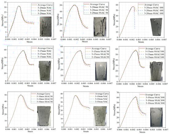
Figure 6.
Uniaxial compressive stress–strain curves and failure modes of concrete with different maximum aggregate sizes and replacement ratios.
All specimens exhibited either splitting failure or a combination of splitting and shear failure, as shown in Figure 6. Concrete specimens with a particle size of 5–20 mm primarily failed in a brittle splitting mode with diagonal cracks, characterized by relatively wide cracks, rapid crack penetration, and a tendency to form oblique main cracks or splitting failure, resulting in rough fracture surfaces. Specimens with a particle size of 5–15 mm showed a mixed failure mode, with oblique cracks developing more slowly and occasionally accompanied by minor shear-sliding failure. Specimens with a particle size of 5–10 mm exhibited ductile failure due to the dispersion and fineness of cracks, primarily through bending or crushing, making rapid instability less likely. Compared with normal concrete specimens, cracks in steel slag concrete appeared slightly later, formed at larger angles relative to the loading direction, propagated faster, and generated a pronounced “pop” sound upon failure, particularly in SSAC100 specimens.
3.1.2. Comparative Analysis of Stress–Strain Curves Under Different Aggregate Size Ranges and Replacement Ratios
The stress–strain relationship of concrete reflects the macroscopic manifestation of its internal damage evolution. The experimentally obtained constitutive curves indicate that the incorporation of SSA not only alters the stiffness and strength of the material but also significantly affects its pre-peak and post-peak mechanical behavior. Figure 7 shows that, under different steel slag contents, the constitutive curves of concrete with various particle size ranges exhibit both ascending and descending branches. Before 0.5 (peak stress), the ascending branch is approximately linear, as shown in Figure 7a. For the same replacement ratio, there is no significant difference in slope among different particle size ranges, and the increase in particle size range has little effect on overall stiffness, resulting in negligible changes in the elastic modulus. In Figure 7b, for the same particle size range, the slope increases systematically with the replacement ratio in the order of 0%, 100%, and 50%, indicating that steel slag incorporation significantly increases the elastic modulus and stiffness of concrete. Between 0.5 and , the strain growth rate slightly exceeds that of stress, the slope begins to decrease, and stress reaches the peak. As illustrated in Figure 7b, the steel slag content affects both the maximum stress and corresponding strain. The maximum stress and corresponding strain of steel slag concrete exceed those of normal concrete, indicating that steel slag as aggregate improves both strength and ductility. Figure 7a shows that, at the same replacement ratio, decreasing the aggregate particle size range increases and delays the peak stress and peak strain, with the effect most pronounced at 0% replacement; for 50% and 100% replacement, peak stress is comparable, but the former has a larger peak strain, indicating better ductility and deformation capacity at 50% replacement. After , the slope changes from positive to negative. As shown in Figure 7b, the curve of normal concrete is fuller, whereas steel slag concrete curves are steeper, resembling brittle failure, and the higher the replacement ratio, the more pronounced the effect on the curve. Figure 7a also shows that, at the same replacement ratio, the descending branch becomes more gradual as the aggregate particle size range decreases, whereas increasing the replacement ratio leads to a steeper descending branch.
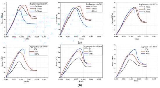
Figure 7.
Stress–strain curves under different aggregate particle size ranges and replacement ratios. (a) Stress–strain curve diagram for different particle size ranges at the same replacement ratio. (b) Stress–strain curve diagram for different substitution rates within the same particle size range.
3.1.3. Characteristic Parameters of Steel Slag Coarse Aggregate Concrete
The characteristic parameters of the constitutive curve include the peak stress, peak strain, elastic modulus, and Poisson’s ratio. The elastic modulus of the concrete specimens (denoted as ) was defined as the tangent modulus of the stress–strain curve measured from 0.4 . Poisson’s ratio was not measured due to equipment limitations. Figure 8 illustrates the effects of steel slag replacement ratio and aggregate particle size range on these characteristic parameters.
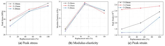
Figure 8.
Effect of replacement ratio on characteristic parameters.
Replacing conventional aggregates with steel slag in concrete can improve its strength, which is consistent with the conclusions drawn by most researchers [56,57,58]. Compared with NA, SSA exhibit superior mechanical and physical properties [59], including lower crushing strength index, higher shear capacity, and better resistance to impact. The crushing value of SSA is less than 50% of that of NA, indicating that concrete contains a higher proportion of steel slag particles at the compression failure interfaces; the incorporated steel slag does not form voids due to particle detachment, whereas ordinary concrete may develop voids from aggregate loss. This demonstrates that steel slag has a stronger bond with the cement paste, and the ITZ is thinner and stiffer than in ordinary concrete [60], reducing the distance between aggregates and the mortar matrix, resulting in a denser structure with higher load-bearing capacity and delayed failure. Additionally, SSA exhibits a pozzolanic effect [61] and possesses a rough, porous surface [62], which increases internal water absorption, reduces the water–cement ratio, and enlarges the contact area with the cement paste, further enhancing its advantages.
The strength-enhancing effect of SSA is most pronounced when the replacement ratio is 50%. As shown in Figure 8a,b, compared with the 0% replacement, the peak stress of concrete with aggregate size ranges of 5–10 mm, 5–15 mm, and 5–20 mm increased by 32.26%, 35.73%, and 45.74%, respectively, while the elastic modulus increased by 66.7%, 71.4%, and 70.1%. These results are closely related to the failure behavior observed in concrete containing steel slag aggregates. Compared with natural aggregate concrete, SSA shares a greater portion of the compressive load, leading to failure that involves the mortar matrix, ITZ, and steel slag aggregates simultaneously. As shown in Figure 7b, for the same aggregate size range, the elastic modulus of SSA concrete initially increases and then decreases with increasing replacement ratio. This phenomenon occurs because ordinary concrete has a relatively low elastic modulus, and the incorporation of high-hardness SSA significantly enhances the overall stiffness. However, at a 100% replacement ratio, the “advantage” of SSA is offset by its “disadvantages” as a result of its elevated porosity and water absorption, which increase the amount of incompletely hydrated products and reduce the effectiveness of the mechanical interaction with the cementitious matrix. Additionally, the f-CaO content may increase [63]; during hydration, f-CaO can expand rapidly, generating additional porosity and microcracks within the concrete. For the same replacement ratio, as the aggregate size range increases, the elastic modulus of concrete with 5–15 mm aggregates is slightly higher than that of the other two size ranges for replacement ratios between 0% and 50%. This is mainly due to the elevated crushing strength of aggregates in the 5–15 mm range, which contributes to a higher overall stiffness of the concrete.
The data in Figure 8c indicate that the peak strain of concrete increases as the SSA replacement ratio rises. For concrete with an aggregate size range of 5–10 mm, the peak strain grows approximately linearly with increasing replacement ratio. For the 5–15 mm range, concrete exhibits the highest peak strain at the same replacement ratio, although the enhancement effect is relatively gradual. This suggests that these specimens possess better ductility and are less prone to brittle failure. In this aggregate size range, concrete can more easily form a dense aggregate skeleton, resulting in higher overall compactness and improved synergy with the mortar, reducing the likelihood of incomplete mortar encapsulation. The moderate stiffness further facilitates stress transfer, leading to a slower failure process. In contrast, for the 5–20 mm range, the enhancement of peak strain transitions from gradual to abrupt. At low SSA replacement ratios, the relatively weak and discontinuous interfacial transition zones (ITZs) between the steel slag aggregates and the cement paste may hinder microcrack propagation, thereby suppressing plastic deformation. These weak and discontinuous ITZs are caused by the high water absorption and rough, porous surfaces of SSA, which reduce mortar flowability and coverage during mixing. Additionally, in concretes with larger aggregate size ranges, local bleeding effects [64] increase the porosity of the lower ITZ and decrease the content of unhydrated cement particles, resulting in brittle failure characterized by high strength and low strain at the bottom.
3.2. Mesoscale Model Simulation Results of Steel Slag Coarse Aggregate Concrete
3.2.1. Validation of the Mesoscale Model
The meso-scale models of NAC and SSAC were developed using the approach described in Section 2.2.1 and calibrated against the experimental stress–strain curves presented in Section 3.1.2. In this section, a mesh sensitivity analysis was conducted to identify an appropriate mesh size for the meso-model.a parametric study was carried out to refine key parameters, including the aggregate elastic modulus, ITZ strength, and fracture energy. Finally, based on the findings of Jin [65], the material parameters for the NAC and SSAC meso-models were proposed, and a back-analysis was performed using the experimental stress–strain curves to validate the accuracy of the simulations.
Mesh Sensitivity Analysis
The meso-scale concrete models were established with mesh densities of 3 mm, 4 mm, and 5 mm, using two element shapes: quadrilateral and triangular. The corresponding total number of elements was 29,800, 24,019, and 20,271 for quadrilateral meshes, and 36,578, 31,064, and 29,162 for triangular meshes. Figure 9 presents the peak stress trends for both quadrilateral and triangular meshes. It can be observed that the triangular mesh shows a significant increase in peak stress with increasing mesh size, whereas the quadrilateral mesh results remain within a 5% error margin and exhibit a relatively smooth and stable trend. Considering both computational efficiency and simulation accuracy, a 4 mm quadrilateral mesh was selected for the meso-scale concrete simulations.
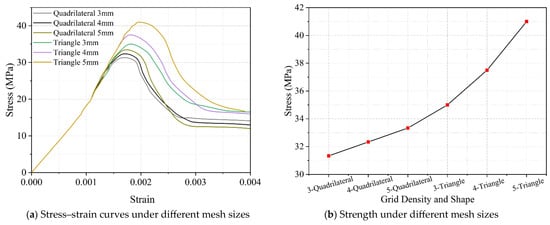
Figure 9.
Influence of different mesh shapes and sizes on simulation results.
Mesoscale Parameters of Steel Slag Coarse Aggregate
To maintain consistency with the experimental tests, a concrete meso-model with dimensions of 150 mm × 150 mm × 300 mm and a coarse aggregate volume fraction of 50% was generated for uniaxial compression. Prior to formal loading simulations, the meso-scale material parameters needed calibration to establish the coupling mechanisms among different constituents. The accuracy of the meso-scale concrete model is closely related to these parameters, which define the interactions between materials and directly influence the macroscopic mechanical behavior. In this study, an inverse method was employed to determine the meso-scale parameters of SSA concrete, enabling the model to accurately simulate various conditions and reveal the intrinsic failure mechanisms. Table 5 presents the compressive strength of the mortar obtained from experiments, with standard deviation denoted as and coefficient of variation as CV. represents the mortar compressive strength, and the mortar elastic modulus was calculated using Equation (7). Table 6 lists the material parameters for NA, referencing results from Jin, Chen, and others [65,66,67]. Parameters marked with “*” were determined through experimental calibration, while the remaining parameters were obtained via inverse analysis of the experimental stress–strain curves.
Table 5.
Compressive strength of mortar at 28 days.
Table 6.
Material parameters of the mesoscale structure.
Experimental findings demonstrate that incorporating SSA in place of NA increases the concrete’s compressive capacity and stiffness, primarily because SSA possesses higher intrinsic strength than NA (as reflected in crushing value differences) and forms stronger bonds with the cement matrix. In this study, 5–20 mm NAC is taken as an example to investigate the effects of aggregate elastic modulus, interface properties (ratio of interface to mortar mechanical properties), and ITZ fracture energy on the stress–strain curve, while all other parameters are kept constant.
As shown in Figure 10a, modifying the aggregate elastic modulus influences the stress–strain curve’s characteristic parameters in the mesoscopic concrete model. A higher aggregate elastic modulus increases the model’s overall elastic modulus, but decreases both the maximum stress and strain at peak points. When the mesoscopic model experiences the same average axial deformation, aggregates with stiffer elastic properties exhibit less deformation, leading to greater strain in the mortar matrix. This reduction in peak stress is due to the mortar matrix failing earlier under lower average axial strain. Setting the elastic moduli of NA and SSA to 60 GPa and 90 GPa, respectively, results in the mesoscopic concrete model’s elastic modulus correlating well with the experimental data.
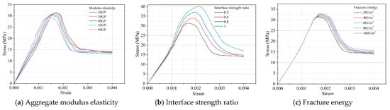
Figure 10.
Stress–strain curves of the model under different aggregate elastic moduli, ITZ strengths, and fracture energies.
The simulation outcomes in Figure 10b,c demonstrate that the strength and fracture energy of the ITZ significantly influence the peak stress and the post-peak behavior of the mesoscopic concrete model. Specifically, higher ITZ strength and fracture energy lead to increased peak stress in the model. Moreover, as the ITZ strength increases, the post-peak region of the stress–strain curve becomes steeper, whereas increasing the ITZ fracture energy results in a fuller descending branch. Accordingly, Wang [68] suggests strengthening the ITZ around SSA to achieve a notable increment in concrete strength. The inversion analysis indicates the cohesive properties around SSA, including the ITZ tensile strength and fracture energy. are enhanced by 75%, 106%, and 92% compared to concrete around NA as the SSA particle size range decreases. These results further confirm that the strength-enhancing effect of SSA can be fully realized across different particle size ranges in concrete.
Validation of Simulation Results
Figure 11 illustrates the failure process under uniaxial compression at 0%, 25%, 50%, 75%, and 100% of the maximum load, using 5–20 mm SSAC100 as an example. Figure 12 shows the stress–strain curves and corresponding failure modes obtained from the simulations. The crack propagation paths and oblique shear failure zones in the mesoscopic concrete models closely resemble the experimentally observed failure patterns. observed in the laboratory tests described in Section 3.1.1, indicating that the developed mesoscopic concrete models are capable of qualitatively reproducing the uniaxial compression behavior of concrete. In addition, the predicted elastic modulus and peak stress, and peak strain are generally consistent with the experimental results, with discrepancies within ±5%. The ascending branch of the simulated stress–strain curve shows only minor differences compared to the laboratory results, which can be neglected. Some differences exist in the descending branch, and these discrepancies increase with higher SSA replacement rates. Nevertheless, numerical simulations maintain a constant loading rate, and the observed differences in the post-peak branch are acceptable. The good overall agreement demonstrates the feasibility of the modeling approach and the reasonableness of the material parameters. Additionally, the scatter among the results of different simulated models is minimal, indicating that the effect of aggregate distribution can be neglected. Therefore, in the subsequent analyses of this study, for each condition, only one mesoscopic model was developed.
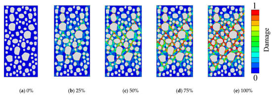
Figure 11.
Uniaxial compression failure process of 5–20 mm SSAC100 under different maximum loads.

Figure 12.
Simulation results: stress–strain curves and failure modes.
Mesoscale finite element simulations further indicate that the spatially random distribution of steel slag coarse aggregates and their relatively high elastic modulus can locally influence the stress–strain response and crack propagation patterns of the model. Even under the same aggregate size range and volume fraction, different aggregate arrangements can cause slight variations in peak strain, initial stiffness, and crack propagation paths. For instance, in the “5–20 mm NAC” case shown in Figure 12, adjusting the positions of steel slag aggregates did not significantly alter the peak strength or overall shape of the stress–strain curve, but minor differences were observed in local curve fluctuations and crack initiation locations. This is mainly attributed to the markedly higher stiffness of steel slag aggregates compared to the surrounding matrix, whereby their relative positions to the ITZ substantially regulate local stress concentrations and crack deflection behavior. However, repeated simulations indicate that these local differences do not affect the overall mechanical trends or the final failure mode of the model. Therefore, the mesoscale finite element model established in this study demonstrates good robustness and representativeness in capturing the mechanical behavior of concrete containing steel slag aggregates
3.2.2. Effect of Coarse Aggregate Volume Fraction on the Strengthening Effect of SSA
In this study, mesoscopic concrete models were employed to investigate the effect of coarse aggregate volume fraction on the strengthening performance of SSA. Four mesoscopic concrete models were established with coarse aggregate volume fractions of 35%, 38%, 41%, and 45%, respectively, with coarse aggregate grading curves consistent with those used in the laboratory tests.
As illustrated in Figure 13, the simulated compressive strength and elastic modulus of 36 groups of concrete with different coarse aggregate volume fractions are presented. For NAC, both compressive strength and elastic modulus decrease with increasing coarse aggregate content. Specifically, when the coarse aggregate volume fraction increases from 35% to 45%, the compressive strength of NAC with aggregate size ranges of 5–20 mm, 5–15 mm, and 5–10 mm decreases by 5.21%, 3.55%, and 5.05%, respectively, while the elastic modulus decreases by 2.8%, 2.16%, and 2.67%, primarily as a result of he higher volume fraction of weak ITZ in concrete models incorporating SSA, the ITZ is no longer the weakest region, exhibiting greater strength than the ordinary natural aggregate matrix. The results indicate that as the coarse aggregate volume fraction rises from 35% to 45%, the compressive strength of SSAC100 with different aggregate sizes increases by 0.68%, 1.2%, and 0.86%, respectively, with the elastic modulus increases by 1.53%, 1.69%, and 1.57%, respectively. For SSAC50, decreasing the aggregate size range from 5–20 mm to 5–15 mm and 5–10 mm results in compressive strength reductions of 1.8%, 1.5%, and 1.62%, respectively, this is attributed to the combined influence of the ITZ surrounding NA and SSA. The enhancement in elastic modulus is minimal, remaining below 1.5%.
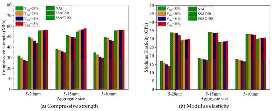
Figure 13.
Simulation results of compressive strength and elastic modulus of concrete with different coarse aggregate volume fractions.
3.3. Research Limitations and Reliability
In this study, several necessary assumptions were made during the experimental tests and numerical simulations, which may influence the interpretation of the results. In the experimental phase, concrete specimens were regarded as macroscopically homogeneous materials, and the potential fluctuations in internal moisture content and curing temperature were not fully considered. Although the loading rate complied with the requirements of relevant standards, its influence on the post-peak mechanical behavior cannot be completely excluded. It should also be noted that the active components on the surface of steel slag aggregates may enhance the performance of the interfacial transition zone (ITZ) in actual conditions, whereas this effect was not separately quantified in the present tests.
In the numerical simulations, coarse aggregates were simplified as rigid or linear elastic materials, and the ITZ was modeled as a uniform layer with constant thickness and mechanical properties. Thus, the potential strengthening effect of the steel slag aggregates’ high stiffness and surface activity on the ITZ was not fully captured. Furthermore, the spatial distribution of aggregates was generated using a random algorithm, which cannot perfectly replicate the actual arrangement but still effectively represents the influence of aggregate packing on local stress development and crack propagation. The mesh size and element type may also affect the representation of failure patterns to some extent.
Despite these limitations, the predicted stress–strain response, peak strength, and crack evolution agree well with the experimental observations, indicating that the proposed model exhibits high reliability. The conclusions derived in this study remain valid under the adopted assumptions and provide valuable insights into the mechanical behavior and strengthening mechanisms of steel slag coarse aggregate concrete.
4. Conclusions
This study systematically investigated the effects of SSA particle size and replacement ratio on the mechanical properties of concrete under uniaxial compression, and further explored the influence of coarse aggregate volume content on the strengthening effect of SSAC. The main conclusions are as follows.
- 1.
- The failure modes of SSAC and NAC are fundamentally similar, with both evolving from the propagation of internal microcracks to the formation of macroscopic diagonal cracks. However, compared with NAC, SSAC with a 5–20 mm aggregate size exhibits faster macroscopic crack development and more pronounced acoustic effects during failure. In terms of mechanical response, the stress–strain curve of SSAC is steeper with a more abrupt descending branch; as the aggregate size range decreases, the descending branch becomes gentler, whereas a rise in the SSA replacement ratio results in a steeper descending branch.
- 2.
- The incorporation of SSA can effectively enhance the peak stress, peak strain, and elastic modulus of concrete. The peak stress increases continuously with the SSA replacement ratio; for a given aggregate size range, the elastic modulus first increases and then decreases with increasing replacement, reaching an optimum at a 50% replacement ratio. At this replacement level, the peak stress of concrete with 5–10 mm, 5–15 mm, and 5–20 mm aggregate ranges increased by 32.26%, 35.73%, and 45.74%, respectively, while the elastic modulus increased by 66.7%, 71.4%, and 70.1%, respectively. In addition, the variation in peak strain with replacement ratio differs with aggregate size, showing linear growth, gradual growth, and a trend from gradual to rapid increase, respectively.
- 3.
- Mesoscale numerical simulation results indicate that as the cohesive strength of the ITZ around SSA is increased relative to NA by 75% (5–20 mm), 106% (5–15 mm), and 92% (5–10 mm), the simulated stress–strain curves are in good agreement with the experimental results. The validated model and parameters can serve as a reference for structural simulations of SSAC under different service conditions.
- 4.
- Increasing the coarse aggregate volume fraction from 35% to 45% has an adverse impact on the mechanical properties of NAC, but exhibits a beneficial strengthening effect on SSAC100 (full replacement), with the enhancement becoming more pronounced at higher coarse aggregate contents.
Author Contributions
Conceptualization, X.L.; Methodology, X.L.; Software, X.L.; Validation, X.L.; Resources, Z.Z. and Q.J.; Data curation, J.G.; Writing—original draft, X.L.; Writing—review & editing, Q.J.; Visualization, Z.Z.; Supervision, Z.Z. and Q.J.; Project administration, Z.Z. and Q.J.; Funding acquisition, J.G. and Q.J. All authors have read and agreed to the published version of the manuscript.
Funding
This work was sponsored by the Outstanding Youth Science Foundation of Natural Science Foundation of Xinjiang Uygur Autonomous Region (grant nos. 2022D01E44) and The Natural Science Foundation of Xinjiang Uygur Autonomous Region (grant nos. 2023D01A33). The APC was funded by the project.
Data Availability Statement
Data will be made available on request.
Acknowledgments
During the preparation of this paper, the authors utilized the finite element software ABAQUS to achieve the desired predictive outcomes. The authors have reviewed and edited the relevant output results and accept full responsibility for the content of this publication.
Conflicts of Interest
The authors declare no conflicts of interest.
References
- Baalamurugan, J.; Kumar, V.G.; Padmapriya, R.; Raja, V.B. Recent applications of steel slag in construction industry. Environ. Dev. Sustain. 2024, 26, 2865–2896. [Google Scholar] [CrossRef]
- Ye, G.; Yuen, K.-V.; Jin, Q.; Zhou, M.; Yin, C.; Jiang, Q.; Zhao, S.; Su, W. Evaluation Method for Uniformity of Steel Slag Concrete Aggregate Based on Improved YOLOv8. J. Build. Eng. 2024, 98, 111046. [Google Scholar] [CrossRef]
- Ma, H.-C.; Geng, Y.; Wang, Q.-H.; Lai, L.-H.; Li, G.-D.; Wang, Y.-Y. Autogenous Shrinkage M-odel for Concrete with Weathered Steel Slag Coarse Aggregate. Structures 2025, 75, 108862. [Google Scholar] [CrossRef]
- Meddah, M.S.; Zitouni, S.; Belâabes, S. Effect of Content and Particle Size Distribution of Coarse Aggregate on the Compressive Strength of Concrete. Constr. Build. Mater. 2010, 24, 505–512. [Google Scholar] [CrossRef]
- Munoz, H.; Taheri, A.; Chanda, E.K. Pre-Peak and Post-Peak Rock Strain Characteristics During Uniaxial Compression by 3D Digital Image Correlation. Rock Mech. Rock Eng. 2016, 49, 2541–2554. [Google Scholar] [CrossRef]
- Neville, A.M.; Brooks, J.J. Concrete Technology; Longman Scientific & Technical: Harlow, UK, 1987. [Google Scholar]
- Neville, A.M. Properties of Concrete, 5th ed.; Pearson Education Ltd.: Harlow, UK, 2011. [Google Scholar]
- Liu, M.; Wang, F. Numerical Simulation of Influence of Coarse Aggregate Crushing on Mechanical Properties of Concrete under Uniaxial Compression. Constr. Build. Mater. 2022, 342, 128081. [Google Scholar] [CrossRef]
- Jia, J.; Cao, Q.; Luan, L.; Wang, Z.; Zhang, L. Mechanical Properties of Large Slump Concrete Made by Post-Filling Coarse Aggregate Mixing Procedure. Materials 2020, 13, 2761. [Google Scholar] [CrossRef]
- Uddin, M.T.; Mahmood, A.H.; Kamal, M.R.I.; Yashin, S.M.; Zihan, Z.U.A. Effects of Maximum Size of Brick Aggregate on Properties of Concrete. Constr. Build. Mater. 2017, 134, 713–726. [Google Scholar] [CrossRef]
- Aïtcin, P.C. High Performance Concrete; CRC Press: Boca Raton, FL, USA, 2011. [Google Scholar]
- Vu, X.H.; Daudeville, L.; Malecot, Y. Effect of Coarse Aggregate Size and Cement Paste Volume on Concrete Behavior under High Triaxial Compression Loading. Constr. Build. Mater. 2011, 25, 3941–3949. [Google Scholar] [CrossRef]
- Ghorbani, S.; Sharifi, S.; Ghorbani, S.; Tam, V.W.; de Brito, J.; Kurda, R. Effect of Crushed Concrete Waste’s Maximum Size as Partial Replacement of Natural Coarse Aggregate on the Mechanical and Durability Properties of Concrete. Resour. Conserv. Recycl. 2019, 149, 664–673. [Google Scholar] [CrossRef]
- Vishalakshi, K.P.; Revathi, V.; Reddy, S.S. Effect of Type of Coarse Aggregate on the Strength Properties and Fracture Energy of Normal and High Strength Concrete. Eng. Fract. Mech. 2018, 194, 52–60. [Google Scholar] [CrossRef]
- Tozsin, G.; Yonar, F.; Yucel, O.; Dikbas, A. Utilization Possibilities of Steel Slag as Backfill Material in Coastal Structures. Sci. Rep. 2023, 13, 4318. [Google Scholar] [CrossRef]
- Roslan, N.H.; Ismail, M.; Abdul-Majid, Z.; Ghoreishiamiri, S.; Muhammad, B. Performance of Steel Slag and Steel Sludge in Concrete. Constr. Build. Mater. 2016, 104, 16–24. [Google Scholar] [CrossRef]
- Wang, S.; Zhang, G.; Wang, B.; Wu, M. Mechanical Strengths and Durability Properties of Pervious Concretes with Blended Steel Slag and Natural Aggregate. J. Clean. Prod. 2020, 271, 122590. [Google Scholar] [CrossRef]
- Cheng, X.; Tian, W.; Gao, J.; Gao, Y. Performance Evaluation and Lifetime Prediction of Steel Slag Coarse Aggregate Concrete under Sulfate Attack. Constr. Build. Mater. 2022, 344, 128203. [Google Scholar] [CrossRef]
- Tian, Y.; Wang, L.; Kong, D.; Zhou, T.; Ren, C.; Yang, R.; Yuan, Q. Effect Evaluation and Mechanism Analysis of Steel Slag Fine Aggregate on the Strengths of Recycled Aggregate Concretes. Eur. J. Environ. Civ. Eng. 2025, 29, 1178–1195. [Google Scholar] [CrossRef]
- Wang, Y.; Zhang, W.; Wang, J.; Huang, R.; Lou, G.; Luo, S. Effects of Coarse Aggregate Size on Thickness and Micro-Properties of ITZ and the Mechanical Properties of Concrete. Cem. Concr. Compos. 2024, 154, 105777. [Google Scholar] [CrossRef]
- Padmanabhan, K.A. Mechanical Properties of Nanostructured Materials. Mater. Sci. Eng. A 2001, 304–306, 200–205. [Google Scholar] [CrossRef]
- Cascardi, A.; Verre, S.; Ombres, L.; Aiello, M.A. Carbon Fabric Reinforced Cementitious Mortar Confinement of Concrete Cylinders: The Matrix Effect for Multi-Ply Wrapping. Compos. Struct. 2024, 332, 117919. [Google Scholar] [CrossRef]
- Deng, K.K.; Wu, K.; Wu, Y.W.; Nie, K.B.; Zheng, M.Y. Effect of Submicron Size SiC Particula-tes on Microstructure and Mechanical Properties of AZ91 Magnesium Matrix Composites. J. Alloys Compd. 2010, 504, 542–547. [Google Scholar] [CrossRef]
- Lin, J.; Zhao, Q.; Chen, H.; Li, M.; Yuan, L. A Numerical Framework for the ITZ Percolation, Effective Fraction and Diffusivity of Concrete Systems Considering the Nonuniform ITZ. J. Build. Eng. 2023, 77, 107429. [Google Scholar] [CrossRef]
- Zhou, Z.; Jin, Q.; Hu, D.; Zhu, L.; Li, Z.; Su, W. Long-Term Volume Stability of Steel Slag Sand Mortar and Concrete. Case Stud. Constr. Mater. 2025, 22, e04179. [Google Scholar] [CrossRef]
- Mitwally, M.E.; Elnemr, A.; Shash, A.; Babiker, A. Utilization of Steel Slag as Partial Replacement for Coarse Aggregate in Concrete. Innov. Infrastruct. Solut. 2024, 9, 175. [Google Scholar] [CrossRef]
- Gao, M.; Wang, J.; Sha, W.; Guo, Y. Physico-Mechanical Properties and Synergistic Hydration Mechanism of Steel Slag-GBFS Based Alkali-Activated Composites Incorporated with Silica Fume. J. Mater. Res. Technol. 2025, 36, 3327–3341. [Google Scholar] [CrossRef]
- Zhao, J.; Li, Z.; Wang, D.; Yan, P.; Luo, L.; Zhang, H.; Zhang, H.; Gu, X. Hydration Superposition Effect and Mechanism of Steel Slag Powder and Granulated Blast Furnace Slag Powder. Constr. Build. Mater. 2023, 366, 130101. [Google Scholar] [CrossRef]
- Bian, Z.; Fang, Y.; Yu, F.; Wang, X.; Xiang, G. Numerical Simulation of Basic Properties of Fu-ll-Steel Slag Aggregate Concrete. Adv. Civ. Eng. 2021, 2021, 8845329. [Google Scholar] [CrossRef]
- Ren, Z.; Li, D. Uniaxial Compressive Behavior Study of Normal-Strength Concrete Using Waste Steel Slag Aggregate through Laboratory Tests and Numerical Simulation. J. Build. Eng. 2024, 85, 108720. [Google Scholar] [CrossRef]
- Ukpata, J.O.; Ewa, D.E.; Success, N.G.; Alaneme, G.U.; Otu, O.N.; Olaiya, B.C. Effects of Aggregate Sizes on the Performance of Laterized Concrete. Sci. Rep. 2024, 14, 448. [Google Scholar] [CrossRef]
- Zeng, M.-H.; Wu, Z.-M.; Wang, Y.-J. A Stochastic Model Considering Heterogeneity and Crack Propagation in Concrete. Constr. Build. Mater. 2020, 254, 119289. [Google Scholar] [CrossRef]
- Hillerborg, A. Results of Three Comparative Test Series for Determining the Fracture energyG F of Concrete. Mater. Struct. 1985, 18, 407–413. [Google Scholar] [CrossRef]
- Rao, G.A.; Prasad, B.K.R. Fracture Energy and Softening Behavior of High-Strength Concrete. Cem. Concr. Res. 2002, 32, 247–252. [Google Scholar] [CrossRef]
- Zhuo, J.; Zhang, Y.; Ma, M.; Zhang, Y.; Zheng, Y. Uniaxial Compression Failure and Size Effect of Recycled Aggregate Concrete Based on Meso-Simulation Analysis. Materials 2022, 15, 5710. [Google Scholar] [CrossRef]
- Schlangen, E.; Garboczi, E.J. Fracture Simulations of Concrete Using Lattice Models: Computational Aspects. Eng. Fract. Mech. 1997, 57, 319–332. [Google Scholar] [CrossRef]
- Zhang, X.; Ding, J.; Zhang, Y. A Rate-Dependent Peridynamic Model of Reinforced Concrete S-ubjected to Explosive Loading. Eng. Fract. Mech. 2023, 292, 109666. [Google Scholar] [CrossRef]
- Kim, K.; Lim, Y.M. Simulation of Rate Dependent Fracture in Concrete Using an Irregular Lattice Model. Cem. Concr. Compos. 2011, 33, 949–955. [Google Scholar] [CrossRef]
- Mohamed, A.R.; Hansen, W. Micromechanical Modeling of Crack-Aggregate Interaction in Concrete Materials. Cem. Concr. Compos. 1999, 21, 349–359. [Google Scholar] [CrossRef]
- Peng, Y.; Chen, X.; Ying, L.; Kamel, M.M.A. Research on Softening Curve of Recycled Concrete Using Base Force Element Method in Meso-Level. Eng. Comput. 2019, 36, 2414–2429. [Google Scholar] [CrossRef]
- Zhou, M.; Ye, G.; Yuen, K.-V.; Yu, W.; Jin, Q. A Graph Attention Reasoning Model for Prefabricated Component Detection. Comput. Civ. Infrastruct. Eng. 2025, 40, 1606–1626. [Google Scholar] [CrossRef]
- GB175-2023; General Portland Cement Released. China’s State Administration for Market Regulation (SAMR): Beijing, China, 2024.
- GB/T 1346-2024; Test Methods for Water Requirement of Standard Consistency, Setting Time and Soundness of the Portland Cement. China Standards Press: Beijing, China, 2025.
- GB/T14685-2011; Specification of Pebble and Crushedstone for Building. China Standards Press: Beijing, China, 2011.
- YB/T 4328-2012; Method for the Determination of Content of Free Calcium Oxide in Steel Slag. Metallurgical Industry Press: Beijing, China, 2012.
- JGJ/T 70-2009; Standard for Test Method of Performance on Building Mortar. Industry Standard of the People’s Republic of China. China Architecture & Building Press: Beijing, China, 2009.
- ISO 7500-1:2004; Metallic Materials—Verification of Staticuniaxial Testing Machines—Part 1: Tension/Compression Testing Machines—Verification and Calibration of the Force-Measuring System, IDT. International Organization for Standardization: Geneva, Switzerland, 2004.
- GB/T 50081-2019; Standard for Test Methods of Concrete Physical and Mechanical Properties. China Architecture Building Press: Beijing, China, 2019.
- Shaik, A.R.; Pandey, A.V.; Karthik, V.; Kolhatkar, A.; Abhishek, G.; Divakar, R. Application of Digital Image Correlation to Small Punch Test for Determination of Stress–Strain Properties. Trans. Indian. Inst. Met. 2024, 77, 3879–3892. [Google Scholar] [CrossRef]
- Peng, Y.; Wang, Q.; Ying, L.; Kamel, M.M.A.; Peng, H. Numerical Simulation of Dynamic Mechanical Properties of Concrete under Uniaxial Compression. Materials 2019, 12, 643. [Google Scholar] [CrossRef]
- Wu, K.; Kang, W.; Xu, L.; Sun, D.; Wang, F.; Schutter, G.D. Damage Evolution of Blended Cement Concrete under Sodium Sulfate Attack in Relation to ITZ Volume Content. Constr. Build. Mater. 2018, 190, 452–465. [Google Scholar] [CrossRef]
- Wu, K.; Shi, H.; Xu, L.; Ye, G.; Schutter, G.D. Microstructural Characterization of ITZ in Blended Cement Concretes and Its Relation to Transport Properties. Cem. Concr. Res. 2016, 79, 243–256. [Google Scholar] [CrossRef]
- Xu, F.; Tian, B.; Xu, G. Influence of the ITZ Thickness on the Damage Performance of Recycled Concrete. Adv. Mater. Sci. Eng. 2021, 2021, 6643956. [Google Scholar] [CrossRef]
- Lubliner, J.; Oliver, J.; Oller, S. A plastic-damage model for concrete. Int. J. Solids Struct. 1989, 25, 299–326. [Google Scholar] [CrossRef]
- Fu, Q.; Xue, G.; Xu, S.; Li, J.; Dong, W. Mechanical Performance, Microstructure, and Damage Model of Concrete Containing Steel Slag Aggregate. Struct. Concr. 2022, 24, 2189–2207. [Google Scholar] [CrossRef]
- Xue, G.; Zhao, Y.; Zhou, H.; Sun, L. Experimental Study on Uniaxial Compressive Stress-Strain Relationship of Steel Slag Coarse Aggregate Concrete. Eng. Mech. 2022, 39, 86–95. [Google Scholar] [CrossRef]
- Huang, Y.; Yang, X.; Wang, S.; Liu, Z.; Liu, L.; Xu, B. Evaluating Cement Treated Aggregate Base Containing Steel Slag: Mechanical Properties, Volume Stability and Environmental Impacts. Materials 2022, 15, 8277. [Google Scholar] [CrossRef]
- Wang, C.; Ye, G.; Jin, Q.; Zhou, Z.; Hu, D.; Wei, Y. The Uniaxial Compressive Stress-Strain Relations of Steel Slag Fine Aggregate Concrete under Steam Curing. Constr. Build. Mater. 2025, 459, 139820. [Google Scholar] [CrossRef]
- Nguyen, T.-T.-H.; Mai, H.-H.; Phan, D.-H.; Nguyen, D.-L. Responses of Concrete Using Steel Slag as Coarse Aggregate Replacement under Splitting and Flexure. Sustainability 2020, 12, 4913. [Google Scholar] [CrossRef]
- Shang, J.; Xing, L. Study on the Interface Transition Zone of Steel Slag Coarse Aggregate Concrete. J. Build. Mater. 2013, 16, 217–220. [Google Scholar] [CrossRef]
- Li, L.; Chen, T.; Gao, X.; Yang, W. New Insights into the Effects of Different CO2 Mineralization Conditions on Steel Slag as Supplemental Cementitious Material. J. Build. Eng. 2024, 84, 108566. [Google Scholar] [CrossRef]
- Brand, A.S.; Roesler, J.R. Interfacial Transition Zone of Cement Composites with Steel Furnace Slag Aggregates. Cem. Concr. Compos. 2018, 86, 117–129. [Google Scholar] [CrossRef]
- Wang, S.; Wang, M.; Liu, F.; Song, Q.; Deng, Y.; Ye, W.; Ni, J.; Si, X.; Wang, C. A Review on the Carbonation of Steel Slag: Properties, Mechanism, and Application. Materials 2024, 17, 2066. [Google Scholar] [CrossRef]
- Peng, Z.; Liu, Q. Effects of aggregate size on the mechanical behaviors of interfacial transition zone and concrete: A DEM study. J. Southeast Univ. (Nat. Sci. Ed.) 2025, 55, 1600–1607. [Google Scholar]
- Jin, L.; Wang, Z.; Jiao, P.; Zhou, P.; Wu, T. Mesoscale-Based Failure Mechanism of Recycled Aggregate Concrete under Axial Compression Considering End Restraint Effect. Mater. Today Commun. 2024, 40, 109549. [Google Scholar] [CrossRef]
- Jin, L.; Yu, W.; Li, D.; Du, X. Numerical and Theoretical Investigation on the Size Effect of Concrete Compressive Strength Considering the Maximum Aggregate Size. Int. J. Mech. Sci. 2021, 192, 106130. [Google Scholar] [CrossRef]
- Chen, H.; Xu, B.; Mo, Y.L.; Zhou, T. Behavior of Meso-Scale Heterogeneous Concrete under Uniaxial Tensile and Compressive Loadings. Constr. Build. Mater. 2018, 178, 418–431. [Google Scholar] [CrossRef]
- Wang, G.; Chen, X.; Dong, Q.; Yuan, J.; Hong, Q. Mechanical Performance Study of Pervious Concrete Using Steel Slag Aggregate through Laboratory Tests and Numerical Simulation. J. Clean. Prod. 2020, 262, 121208. [Google Scholar] [CrossRef]
Disclaimer/Publisher’s Note: The statements, opinions and data contained in all publications are solely those of the individual author(s) and contributor(s) and not of MDPI and/or the editor(s). MDPI and/or the editor(s) disclaim responsibility for any injury to people or property resulting from any ideas, methods, instructions or products referred to in the content. |
© 2025 by the authors. Licensee MDPI, Basel, Switzerland. This article is an open access article distributed under the terms and conditions of the Creative Commons Attribution (CC BY) license (https://creativecommons.org/licenses/by/4.0/).