You are currently viewing a new version of our website. To view the old version click .
Buildings
  • Article
  • Open Access

14 November 2025

Synergistic Microstructures, Mechanical Properties, and Piezoresistive Performance Improvement of Nanoengineered Cementitious Composites by CNT and GNP

,
,
,
,
and
1
Zhejiang Tongtu Traffic Engineering Co., Ltd., Hangzhou 310051, China
2
Tongshun Greening and Landscape Engineering Co., Ltd., Jiashan 314100, China
3
College of Civil Engineering and Architecture, Zhejiang University, Hangzhou 310058, China
*
Author to whom correspondence should be addressed.
This article belongs to the Special Issue Properties and Applications of Sustainable Construction Materials

Abstract

Graphene Nanoplatelets (GNPs) and Carbon Nanotubes (CNTs) are important components for smart infrastructure and structural health monitoring, as they possess excellent mechanical and piezoresistive properties. However, current research on GNP-CNT nanoengineered composites remains in its infancy. Herein, the effects of GNP-CNT admixtures with varying contents on the mechanical strength, microstructures, and piezoresistive properties of cement-based materials were investigated. Scanning electron microscopy (SEM) observations confirmed the uniform dispersion of GNPs and CNTs in the cement matrix (with no severe agglomeration), and physical interactions between these nanomaterials contributed to enhanced pore filling. Mechanical tests showed that GNP-CNT admixtures maintained compressive strength but significantly improved flexural strength. Specifically, at a total nanomaterial content of 0.5%, the flexural strength was enhanced by more than 30%. Both CNTs and GNPs exhibit favorable piezoresistive performance at low stress, while CNTs dominate the piezoresistive performance at high stress. A four-probe method revealed that CNTs can effectively improve the linearity of piezoresistive performance, enabling distinct resistivity changes even under high stress (attributed to unclosed tiny interfacial gaps). Additionally, the admixture of 0.25% GNPs + 0.25% CNTs yielded optimal piezoresistive performance. These results deepen the understanding of synergistically nanoengineered cementitious composites by CNT and GNP and provide GNP-CNT modified composite materials in smart self-monitoring infrastructures.

1. Introduction

Cement-based materials [,,], as the most widely used construction materials in civil engineering, play an irreplaceable role in infrastructure construction. There has been a growing demand for cement-based materials with specialized functionalities beyond structural strength improvement, such as self-monitoring capabilities [,,], thermal management, and acoustic absorption [,,]. Carbon-based materials exhibit significant potential for functional regulation. Currently, the most commonly used carbon-based fillers in cement-based composites include graphene nanoplatelets (GNPs) [], carbon fibers (CFs) [], and carbon nanotubes (CNTs) []. Existing studies have demonstrated that carbon fibers are constrained by factors such as fiber length: they are prone to breakage and entanglement during mixing, leading to uneven dispersion. Against this backdrop, nanoscale carbon-based materials (with a size range of 1–100 nm) have gradually become a research hotspot, which can avoid issues such as fiber breakage and macroscopic agglomeration in composites. Besides, their nanoscale dimensions enable them to fill the nanoscale pores in the cement matrix [], optimizing the material’s microstructure and improving its mechanical performance. Additionally, their large specific surface area enhances the interfacial bonding strength between the filler and the cement matrix. This interfacial enhancement not only promotes the hydration and nucleation rates of the cement matrix but also regulates the formation and distribution of hydration products-ultimately contributing to the comprehensive improvement of composite performance [,].
GNP and CNT have attracted extensive attention in the modification of cement-based materials due to their excellent mechanical properties, electrical conductivity, and chemical stability. GNP, with its unique two-dimensional sheet-like structure and high specific surface area, can effectively fill the pores in the cement matrix, hinder the propagation of microcracks [,,], and thus improve the mechanical properties of composites []. Wang et al. [] found that adding 0.05 wt.% GNP could improve flexural strength by 15–24% and compressive strength by 3–8% via accelerating hydration and refining pore structure. Massion et al. [] conducted experimental investigations on the effect of GNP on mechanical properties of wellbore cement and found that adding GNPs to Class-H cement slurry could significantly improve Young’s modulus and axial peak stress. Du et al. [] conducted experimental investigations on the effect of GNP on durability of concrete and found that adding 2.5% GNP into concrete could improve the long-term performance. Meanwhile, its excellent electrical conductivity enables cement-based materials to exhibit piezoresistive properties, i.e., the ability to change resistivity in response to external stress, which lays a foundation for their application in stress sensing. Kishore et al. [] investigated the effect of varying GNP content on the piezoresistive properties of composite materials. They found that with an increase in GNP content, both the electrical conductivity and the sensitivity coefficient of the composites increased progressively. Tao et al. [] investigated the piezoresistive behavior of GNP-reinforced cement-based composites and found that the addition of GNPs could make the resistivity of cement-based materials change significantly under low stress. Fan et al. [] conducted experimental and investigations on the electrical conductivity of graphene-reinforced cement composites and found that GNP enhanced electrical conductivity. However, existing studies have shown that GNP-modified cement-based materials have obvious limitations in piezoresistive performance: when the GNP-reinforced cement-based composites are subjected to high stress, the interfacial gaps are closed completely, leading to a significant decrease in piezoresistive sensitivity [].
CNT, as a one-dimensional nanomaterial with an ultra-high aspect ratio, has significant advantages in enhancing the durability, compressive strength, and flexural strength of cement-based materials [,,,]. Han et al. [] found that when the CNT content was 0.2%, the water absorption coefficient, water permeability coefficient, and gas permeability coefficient of cement-based materials all decreased, indicating that the durability of the materials was improved. Li et al. [] found that cement-based materials mixed with 0.3% CNT had higher compressive strength in both dry environments and cycles. Elena et al. [] conducted experimental investigations on the effect of multi-walled carbon nanotubes (MWCNTs) on the mechanical properties of cement mortar and found that adding 0.02 wt.% MWCNTs could increase the ultimate compressive strength by 25% and flexural strength by 20% at 90 days curing time. Cui et al. [] found that the adding 0.5 wt.% CNTs in microencapsulated phase-change material (MPCM)-modified cement paste could enhance flexural strength by up to 41% and compressive strength by up to 5%. Furthermore, CNT’s tubular structure can form a continuous conductive network in the matrix [], and the tiny gaps at its interface with the matrix are not easily closed under high stress—this helps to maintain the piezoresistive response under high stress []. Jia et al. [] found that CNT-reinforced concrete exhibited electrical conductivities in the 10−4 S/m range (semiconductive behavior), with 0.006 wt.% CNTs yielding the highest conductivity for sensing applications. Elena et al. [] found that adding 0.01 wt.% MWCNTs resulted in up to a 10% decrement in electrical resistivity at 28 and 90 days curing, effectively enhancing conductivity. Nevertheless, there are still issues with the resistivity performance of CNT-modified cement-based materials: for instance, CNTs are prone to agglomeration due to van der Waals forces, which weakens their reinforcing effect and limits the stability of piezoresistive performance [].
The combined utilization of GNPs and CNTs is expected to mitigate their respective limitations and may have synergistic effect on microstructures, which could further enhance piezoresistive performance. Specifically, cementitious composites reinforced with both GNPs and CNTs exhibit superior mechanical properties and excellent piezoresistive performance throughout the stress process. Extensive researches have been conducted on the synergistic modification of cement-based materials via composite nanocarbon materials [,]. The combination of GNP and CNT is expected to integrate their respective advantages: GNP can exert effects in physical filling and low-stress piezoresistive response, while CNT can optimize the conductive network and improve the linearity of piezoresistive performance under high stress. However, current research on GNP-CNT nanoengineered composites is still in its infancy. The influence of different GNP/CNT ratios on the microstructure, mechanical properties, and piezoresistive behavior of composites remains unclear, and the synergistic mechanism by which these two nanomaterials regulate piezoresistive performance under different stress levels lacks a systematic explanation. Further experiments and research are still needed to explore the roles of GNP and CNT in cement-based composite materials.
In this study, different ratios of GNP/CNT were added to cement-based composite materials. Eleven groups of samples were designed to investigate the synergistic effects of GNP and CNT on mechanical strength, microstructure, and piezoresistive properties. Through mechanical tests, piezoresistive performance tests, pore structure analysis (MIP), and microstructure characterization (SEM, XRD, TG/DTG, FTIR), this research systematically explored the mechanism of strength changes and piezoresistive response under cyclic stress. These findings are expected to provide a theoretical basis and technical support for the development of high-performance intelligent cement-based sensing materials, and promote the application of nanocarbon composite-modified cement-based materials in the field of structural health monitoring.

2. Materials and Experiments

2.1. Materials

The cement employed in this experiment is Portland cement with a strength grade 42.5, whose chemical and mineral compositions are detailed in Table 1. The aggregate used here is Xiamen ISO standard sand, characterized by a SiO2 content of over 96%, a fineness modulus ranging from 2.3 to 3, a loss on ignition of less than 0.4%, and a clay content not exceeding 0.2%. The main physical properties of GNPs and CNTs are summarized in Table 2. The micro morphology of the GNP and CNT samples is presented in Figure 1. GNPs exhibit a typical sheet-like structure with a relatively large diameter but very thin thickness, while CNTs are formed by the curling of sheet-like graphene, presenting a tubular shape with an ultra-high aspect ratio. Due to these structural features, they tend to entangle with each other and form clustered agglomerations.
Table 1. Chemical and mineral compositions of cement (%).
Table 2. Physical and chemical properties of GNP and CNT.
Figure 1. Typical SEM images of GNP and CNT: (a) GNP; (b) CNT.
The dispersant used in this experiment is melamine, which is produced by BASF MELMENT®F10 in Gatersleben, Germany. Its detailed properties are presented in Table 3. Notably, melamine-based dispersants are also widely utilized as water reducers in cementitious materials.
Table 3. Properties of melamine dispersant.

2.2. Sample Preparation

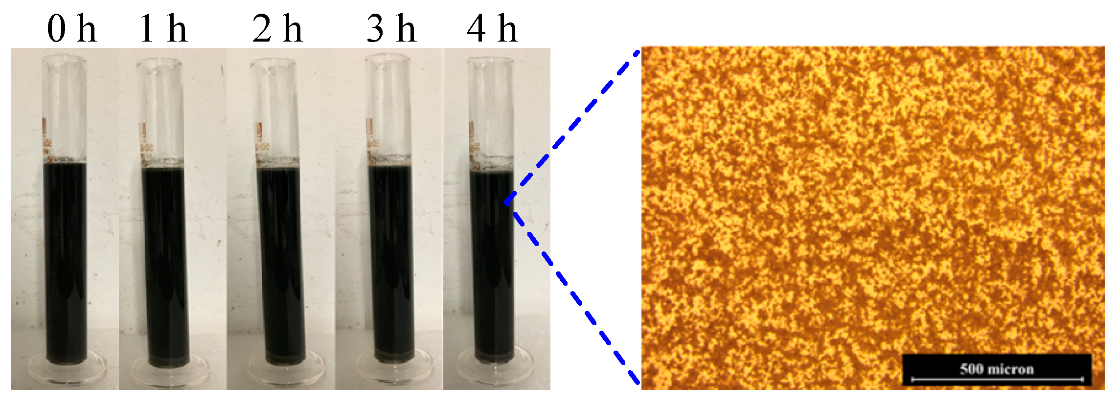
A total of eleven samples were designed to investigate the synergistic effects on the mechanical properties, microstructures, and piezoresistive performance of cement mortars. Among them, Ref served as the control group, with no nanomaterials incorporated. The remaining samples were formulated with GNPs and CNTs, where the total mass fractions of GNPs and CNTs relative to the mass of cement were set at 0.1% and 0.5%, separately. The specific contents of GNPs and CNTs in each sample are detailed in Table 4. Owing to complex interactions such as surface hydrophobicity, intermolecular forces, and electrostatic attraction, nanomaterials are highly susceptible to agglomeration in aqueous solutions. This phenomenon, in turn, induces defects and impairs the performance of cementitious systems. Therefore, the primary step was to fabricate uniformly dispersed GNP-CNT suspensions. As presented in Figure 2, the left ones are sedimentation results of GNP-CNT suspensions and the right one displays a 500× optical micrograph of the GNP-CNT suspension after a standing period. The addition of the melamine can make the particle size of the GNP-CNT mixtures very small—an outcome that effectively promotes the uniform dispersion of the GNP-CNT suspensions.
Table 4. Mix proportions of GNP-CNT nanoengineered composites.
Figure 2. Sedimentation results of GNP-CNT suspension from 0 h to 4 h (left) and a 500× optical micrograph after a standing period (right).
The detailed procedure is described as follows (see Figure 3): A precisely weighed quantity of melamine dispersant (as specified in Table 3) was initially mixed with water in a beaker via manual stirring until complete dissolution was achieved. Subsequently, GNPs and CNTs were carefully added to the beaker. The mixture was then subjected to ultrasonic vibration using a high-power ultrasonic probe for 5 min, followed by a cooling period in a water bath. This ultrasonic vibration-cooling cycle was repeated three times to ensure the homogeneous dispersion of the nanomaterials.
Figure 3. Flowchart of sample preparation and test methods. (a) Preparation of GNP-CNT suspensions; (b) Sample preparation; (c) Mechanical test; (d) Piezoresistive test.
Upon completion of the GNP-CNT suspensions, sample preparation was initiated. First, cement powder and sand were poured into a mixer and blended at low speed for 3 min, with the water-cement ratio maintained at 0.35. Subsequently, the prepared GNP-CNT suspension was added to the mixer, followed by another 3 min of low-speed mixing. Manual scraping was performed to remove any mortar adhering to the mixer blades and inner walls, ensuring thorough integration. The mixture was then stirred at high speed for 1 min to obtain a homogeneous mortar slurry. Each batch of mortar slurry was poured into six pre-greased steel molds with dimensions of 40 mm × 40 mm × 160 mm, followed by a vibration process to eliminate entrapped air within the mortar matrix. Among these molds, three specimens were allocated for compressive and flexural strength tests, while the remaining three were designated for piezoresistive performance evaluations.

2.3. Tests and Methods

The following sections would provide detailed introductions to the experimental processes of the mechanical properties, piezoresistive performance, and microstructure the samples:

2.3.1. Mechanical Properties Test

Mechanical property tests (shown in Figure 3c) primarily include flexural strength and compressive strength evaluations. All tests were conducted in accordance with the standard GB/T 17671-1999 [] using a 25T high-performance fatigue testing machine (Instron Type 8802, Instron Corporation, Norwood, MA, USA). The loading rates were set at 144 kN/min for compressive strength tests and 3 kN/min for flexural strength tests, respectively. For each group, flexural strength was first determined using the central loading method. Subsequent to the flexural test, the broken prismatic specimens were used for the compressive strength test, with a compression area of 40 mm × 40 mm. For each experimental group, the flexural strength was determined as the average value of three prismatic specimens. Meanwhile, the compressive strength was calculated as the arithmetic mean of six measured values.
The unit of flexural strength Rf is MPa, and it is calculated according to Equation (1):
R f = 1.5 F f L b 3
where Ff is the load applied to the prism when it breaks (N); L is the distance between the supporting cylinders (mm); b is the side length of the square cross-section of the prism (mm). In this experiment, L = 100 mm, b = 40 mm.
The unit of compressive strength Rc is MPa, and it is calculated according to Equation (2), where Fc is the maximum load applied to the prism when it breaks (N); A is the compressive area (mm2). In this experiment, A equaled 40 × 40 = 1600 mm2.
R c = F c A

2.3.2. Piezoresistive Test

The piezoresistive performance of the composite materials was measured using the four-probe method (shown in Figure 3d) [], a technique widely recognized for its accuracy in resistivity measurement. All specimens underwent drying treatment at 80 °C for 24 h to eliminate the effect of free water on the electrical conductivity results, ensuring the reliability of the measured data. To avoid direct contact between the specimens and the testing apparatus (which could potentially interfere with and distort the electrical resistivity results), Teflon insulating plates were placed at both ends of each specimen during testing. After that, the specimens were loaded by the Instron Type 8802 to apply cyclic stresses of varying magnitudes. Five different stress levels were designed, and each stress level was cycled three times to ensure data reliability. The load waveform was a triangular wave, with the maximum load set at 60% of the minimum compressive strength of the specimens, ranging from 6 kN to 30 kN. The stress increased by 6 kN per level, and the loading rate was 0.5 kN/s.
When loads were applied to the mortar samples, the electrical resistivity of the composite material changed due to its piezoresistive property. The piezoresistive property can be expressed by the electrical resistivity change rate, as shown in Equation (3), where R0 is the initial resistance (Ω); R(t) is the instantaneous resistance (Ω).
δ R R 0 = R t R 0 R 0

2.3.3. Microstructure Test

Before the test, the samples were dried for 24 h at a temperature of 60 °C. Mineral analyses of cement-based materials are identified using X-ray Diffraction (XRD) [] and Thermal Gravimetry/Differential Thermal Gravimetry (TG/DTG) []: specifically, XRD is employed to analyze the lattice structure and determine their relative contents, while TG/DTG is mainly used to characterize the physical and chemical changes of the sample during temperature variation. Before the analyses, the samples were dried for 24 h at 60 °C, which was intended to protect the sample microstructure from damage caused by high temperatures []. Additionally, Fourier Transform Infrared Spectroscopy (FTIR) [] is a viable technique which could identify the types of chemical bonds and oxygen-containing functional groups in materials based on the different absorption frequencies of infrared light.
The pore structure characteristics of the specimens were analyzed via mercury intrusion porosimetry (MIP) [] using an Autopore IV 9510 instrument (Micromeritics Instrument Co., Ltd., Norcross, GA, USA), with an equilibrium time of 10 s set for each applied pressure level. Diameter of pore size was calculated using the Washburn equation (Equation (4)), based on the assumption that pores exhibit an ideal cylindrical morphology with dimensions gradually decreasing from the exterior to the interior.
r = 2 γ cos θ P
Here, r denotes the pore diameter; γ is the surface tension of liquid mercury, which was set to 485 mN/m; θ represents the contact angle, fixed at 130°; and P is the intrusion pressure, which can be obtained from the MIP measurements. During the MIP testing process, the intrusion pressure was applied progressively from 0.54 psi (3.7 kPa) to 60,000 psi (414 MPa).
The surface microstructure was characterized via a scanning electron microscope (SEM) called Quanta FEG650. Test specimens were harvested from the fractured segments of samples after mechanical property testing, and their dimensions were restricted to less than 1 cm to meet the requirements of SEM observation. Subsequently, the specimens were mounted on the sample stage using conductive adhesive to ensure effective electrical conduction, followed by gold sputtering coating to improve electron signal detection and prevent charge buildup. To reduce potential distortion of microstructure images caused by high acceleration voltages, a low acceleration voltage of 20 kV was consistently employed in this study for image capture. The working distance was maintained within the range of 10–15 mm to balance imaging resolution and depth of field.

3. Results and Discussion

3.1. Mechanical Properties

The calculated compressive strength and flexural strength results are presented in Figure 4, where the compressive and flexural strength values with only GNPs or CNTs were provided for comparison []. It is evident that the addition of nanomaterials exerts distinct effects on the compressive strength and flexural strength of cement-based materials, findings consistent with the conclusions reported by Wang [], Qin [], and Zaheer [] et al. Specifically, Nazari et al. demonstrated that adding 0.05 wt.% GNPs enhances flexural strength by 15–24%. Qin et al. further observed that 0.1 wt.% GNPs improve flexural strength by 37.8%, while exerting a less significant impact on compressive strength from 0.1 wt.–0.5 wt.%. Additionally, Zaheer found that 0.5 wt.% CNTs increase flexural strength by 11.5%. In this experiment, similar trends were observed: the addition of 0.1 wt.% GNPs and 0.5 wt.% CNTs improved flexural strength by approximately 30% and 9.7%, respectively. These results align well with the aforementioned literature, thereby verifying the reliability of the experimental data in this work.
Figure 4. Flowchart of sample preparation and test methods: (a,b) are compressive strength and flexural strength of 0.1% GNP-CNT admixture; (c,d) compressive strength and flexural strength of 0.5% GNP-CNT admixture.
As for the GNP-CNT admixtures, it could be concluded that as the total content of the GNP-CNT admixtures increased, the flexural strength of the material exhibited a corresponding upward trend. When the content of the GNP-CNT admixtures reached 0.5%, the flexural strength increased by over 30%, it could be attributed to the filling effect and template effect of uniformly dispersed GNP-CNT suspension [], which can effectively reduce the porosity of the matrix and inhibit the initiation and propagation of cracks, indicating that the GNP-CNT admixtures can effectively enhance the flexural strength of the composite material.
Furthermore, it is noteworthy that the maximum values of both compressive strength and flexural strength from GNP-CNT cement mortars are higher than those obtained with individual CNT addition. This may be due to the fact that the content of CNTs has exceeded the optimal content for improving compressive and flexural strength. Consistent with this inference, previous studies have reported that the optimal content is 0.048% []. In addition, when the content of the GNP-CNT admixtures is relatively low (0.1%), the strength fluctuated significantly with variations in the GNP/CNT ratio. In contrast, when the content of the GNP-CNT admixture is relatively high (0.5%), the changes in strength values are minor, indicating low sensitivity to the GNP/CNT ratio. This phenomenon may be attributed to the following mechanism: when the content of GNP-CNT admixtures is low, the insufficient quantity of GNP-CNT fails to form a stable reinforcing network within the matrix; in contrast, at an admixture content of 0.5%, a dense and interconnected GNP-CNT network is formed, which dominates the strength enhancement effect, and adjustments to the GNP/CNT ratio barely impair the integrity of this network.

3.2. Piezoresistive Performance

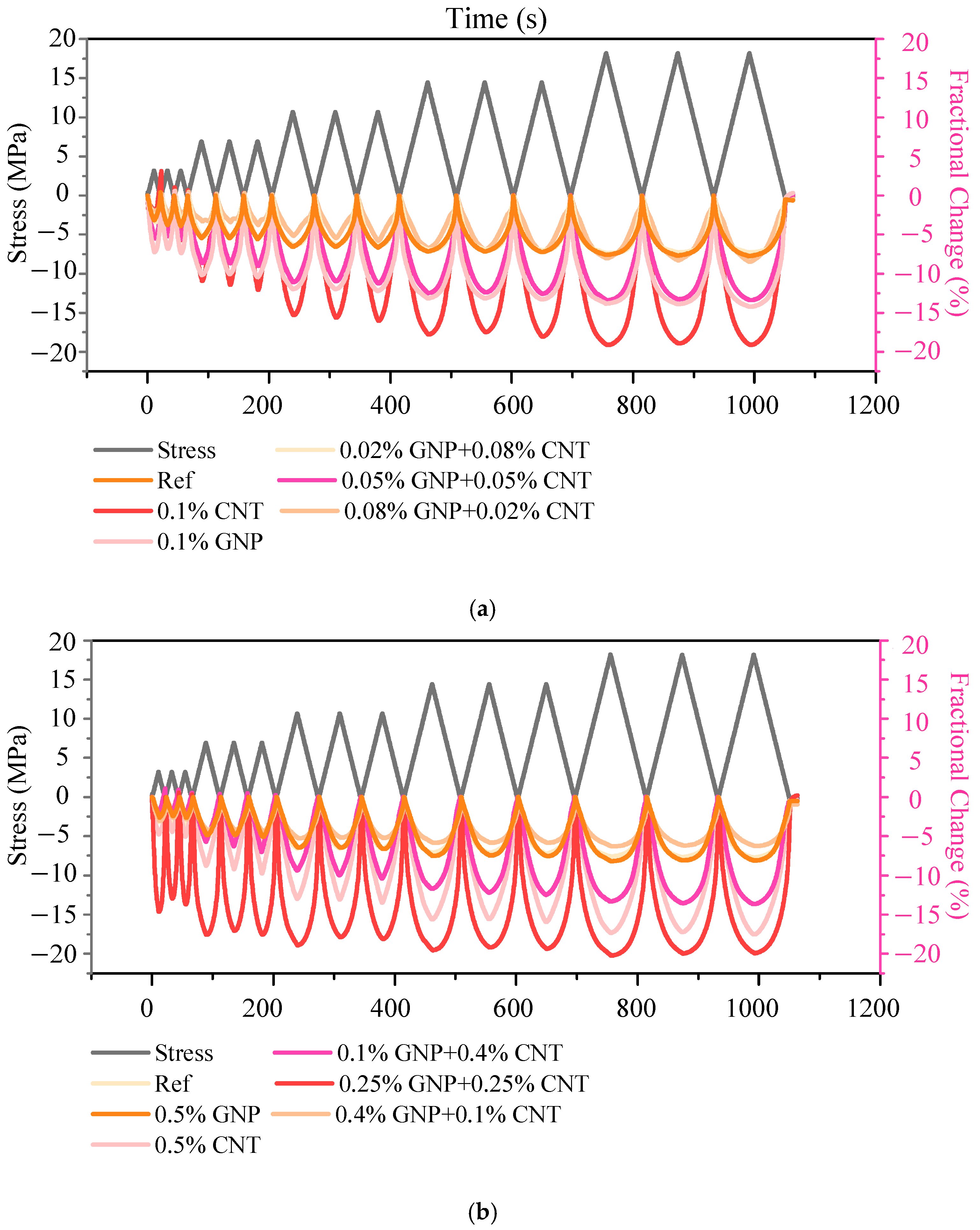
Figure 5 illustrates the fractional variations in electrical resistivity over time. All specimens exhibited distinct piezoresistive behavior, which is characterized by dynamic changes in electrical resistivity in response to applied stresses. Moreover, the absolute magnitude of the electrical resistivity change rate showed a positive correlation with load increments, conversely, it decreased as the load was reduced. This phenomenon can be ascribed to that: load increments reduce the distance between conductive fillers [], thereby facilitating the formation of conductive paths or shortening the separation distance between GNPs and CNTs. Additionally, the GNP/CNT ratio exerted a significant influence on the resistivity. Specifically, when the contents of GNP and CNT were equivalent (0.05% GNP + 0.05% CNT and 0.25% GNP + 0.25% CNT, Figure 5a,b), the piezoresistive performance was remarkably enhanced. This observation may be explained by the fact that equivalent contents of GNP and CNT optimize their dispersion in the matrix, avoid agglomeration, and facilitate the formation of a continuous conductive network. Furthermore, with the increase in the total content of the GNP-CNT admixtures, a denser and more interconnected conductive network is formed, which in turn leads to a more significant improvement trend in piezoresistive properties. This finding is consistent with the conclusion reported by Liu et al. [].
Figure 5. Relative (fractional) changes in electric resistivity with time: (a) 0.1% GNP-CNT admixture; (b) 0.5% GNP-CNT admixture.
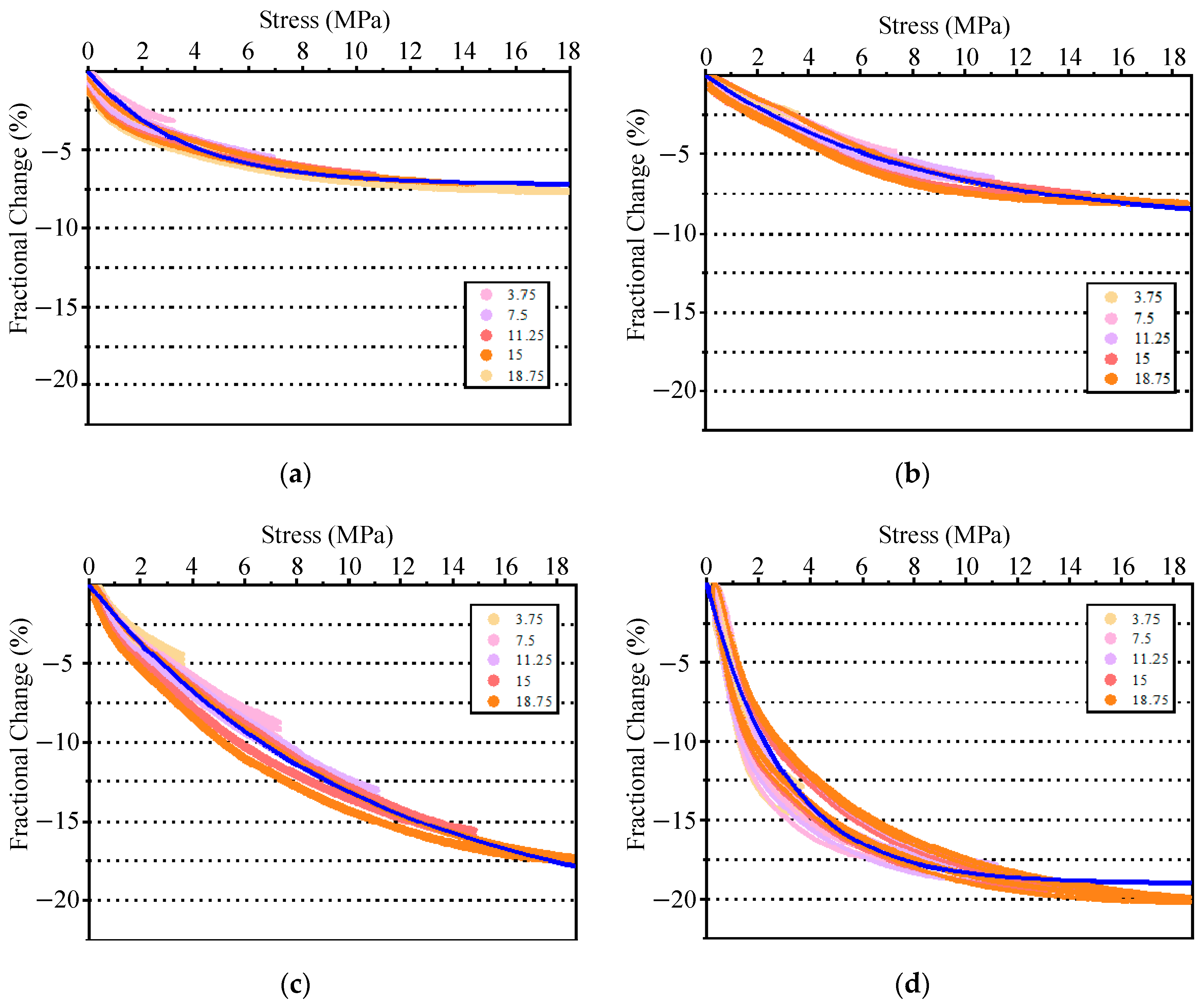
Figure 6 presents the relative changes in electrical resistivity of all cement mortar samples under cyclic stresses. It is observed that the electrical resistivity change rate of all samples follows an exponential degradation relationship with the applied stress. In addition, when the CNT content in the GNP-CNT admixtures is relatively high, the electrical resistivity exhibits a change that approximates a linear relationship with increasing stress (see Figure A1c,f). This phenomenon may be attributed to the formation of numerous tiny gaps or pores at the interface between CNT and the cement matrix, which do not fully close under low stress [], thereby preserving interface effects even under high-stress conditions. Conversely, when the GNP content is relatively high, the electrical resistivity exhibits a curvilinear relationship. Specifically, under low-stress conditions, the changes in electrical resistivity are distinct, indicating favorable piezoresistive properties; however, under high-stress conditions, the resistivity remains unchanged (see Figure A1e,g). This may be because the interfacial gaps have been closed and stable conductive networks were formed under low-stress conditions. When the contents of GNP and CNT are equivalent, the changes in electrical resistivity are exhibited with both good repeatability and linearity, which will be explained in Section 4. Furthermore, with the increase in the total content of the admixtures, the magnitude of electrical resistivity changes gradually increased, and the piezoresistive performance was significantly enhanced (see Figure 6d and Figure A1d). Based on the comprehensive analysis of experimental results, the optimal piezoresistive performance is achieved when the admixture content is 0.25% GNP + 0.25% CNT.
Figure 6. Relative (fractional) changes in electric resistivity with stress and fitting curves: (a) Ref; (b) 0.5% GNP; (c) 0.5% CNT; (d) 0.25% GNP + 0.25% CNT.
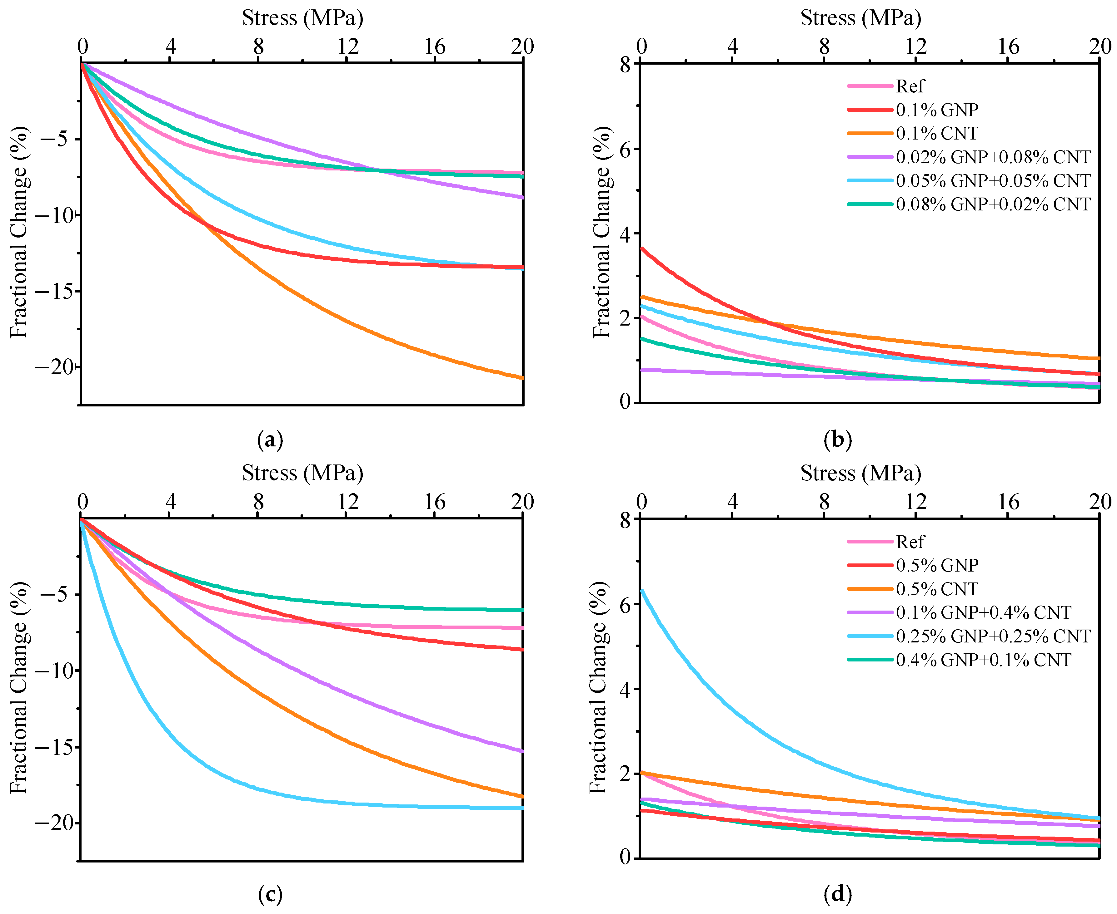
Figure 7 presents the summary and analysis of stress sensitivity for GNP-CNT cement mortars. The addition of GNP and CNT at equal contents significantly enhanced the piezoresistive sensitivity of cement-based materials when the total admixture reached 0.1% and 0.5%. Experimental data further revealed that when the CNT content in the cement-based materials is relatively high, the changes in electrical resistivity decreased almost linearly with increasing stress, exhibiting stable piezoresistive sensitivity. This phenomenon is attributed to the fact that the gaps between CNTs can still be reduced even under high stress conditions. In contrast, when the GNP content is relatively high, the changes in electrical resistivity increased rapidly under low stress conditions, whereas they remain nearly unchanged under high stress, which is due to the fact that the gaps between GNPs are nearly closed under low stress. All these phenomena will be further elaborated in Section 4.
Figure 7. Summary of the fractional changes in electric resistivity with stress and sensitivity: (a,b) are the fractional change and sensitivity of 0.1% GNP-CNT admixture; (c,d) are the fractional change and sensitivity of 0.5% GNP-CNT admixture.

3.3. Chemical Analysis

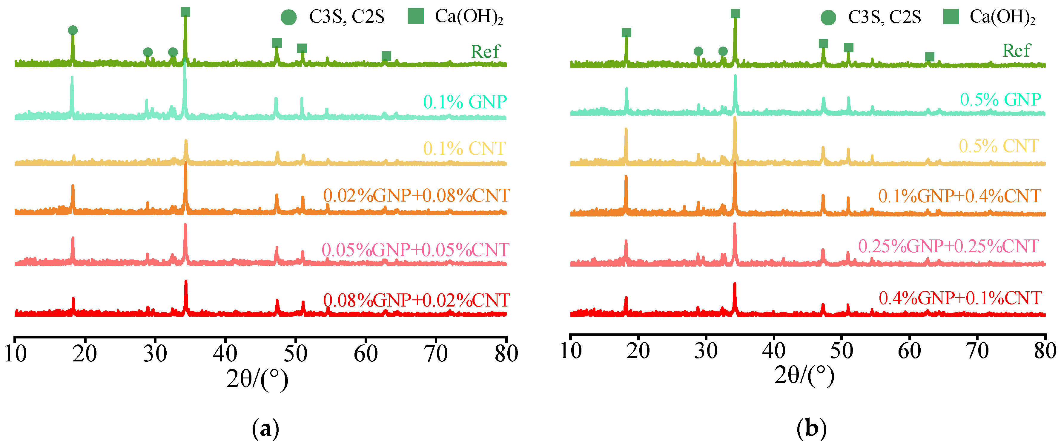
As illustrated in Figure 8, the XRD analysis results reveal that the addition of GNP and CNT did not alter the crystalline phases or structural characteristics of the cement-based matrix. The primary crystalline components remain calcium hydroxide (CH) and unhydrated cement particles, which is consistent with those of the unmodified matrix. Additionally, there is no apparent variation in the peak intensities of the XRD patterns among the tested samples, indicating that GNPs and CNTs exert no substantial influence on the hydration products of the cement paste.
Figure 8. Results of XRD: (a) 0.1% GNP-CNT admixture; (b) 0.5% GNP-CNT admixture.
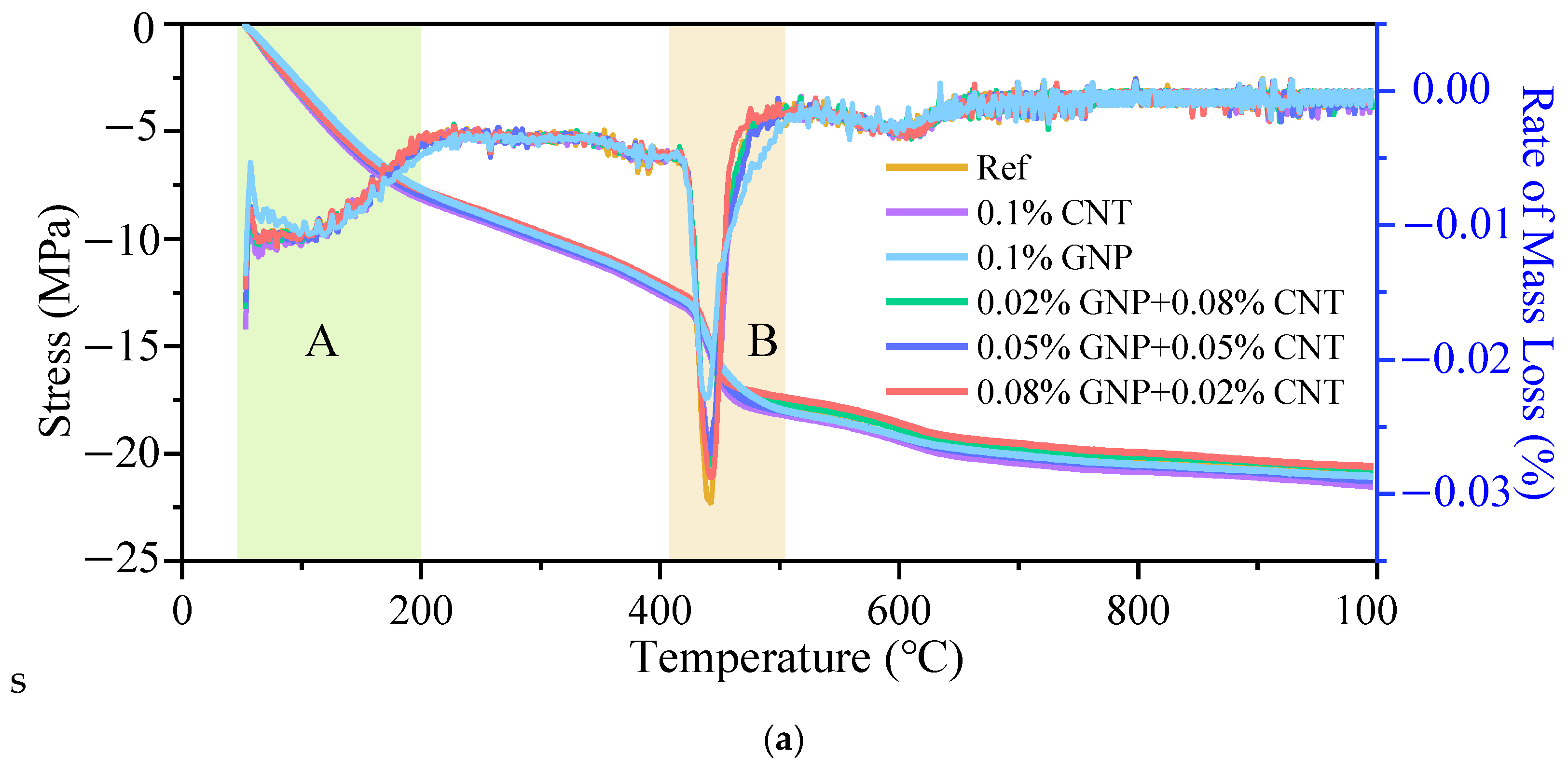
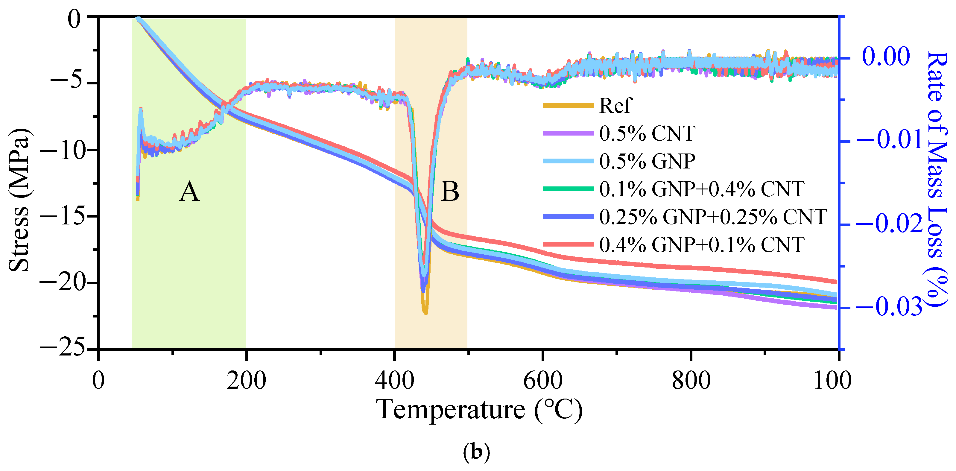
The TG/DTG analysis results are presented in Figure 9. Consistent with previous research findings [], the mass loss curves of all specimens exhibited a high degree of overlap, and the weight loss peak corresponding to the thermal decomposition of CH was also identical. This indicates that GNP and CNT do not exert a significant influence on the chemical composition of the composite materials, which is consistent with the XRD analysis results (Figure 8). As observed from the curves, there are two distinct stages of mass loss (A and B). The first stage of mass loss occurred at low temperatures (<200 °C), corresponding to region A in Figure 9a, which is primarily attributed to the evaporation of free water within the specimens and the decomposition of ettringite and gypsum []. The second stage of mass loss takes place approximately at 450 °C, resulting from the decomposition of CH, as indicated in area B.
Figure 9. Results of TG/DTG: (a) 0.1% GNP-CNT admixture; (b) 0.5% GNP-CNT admixture.
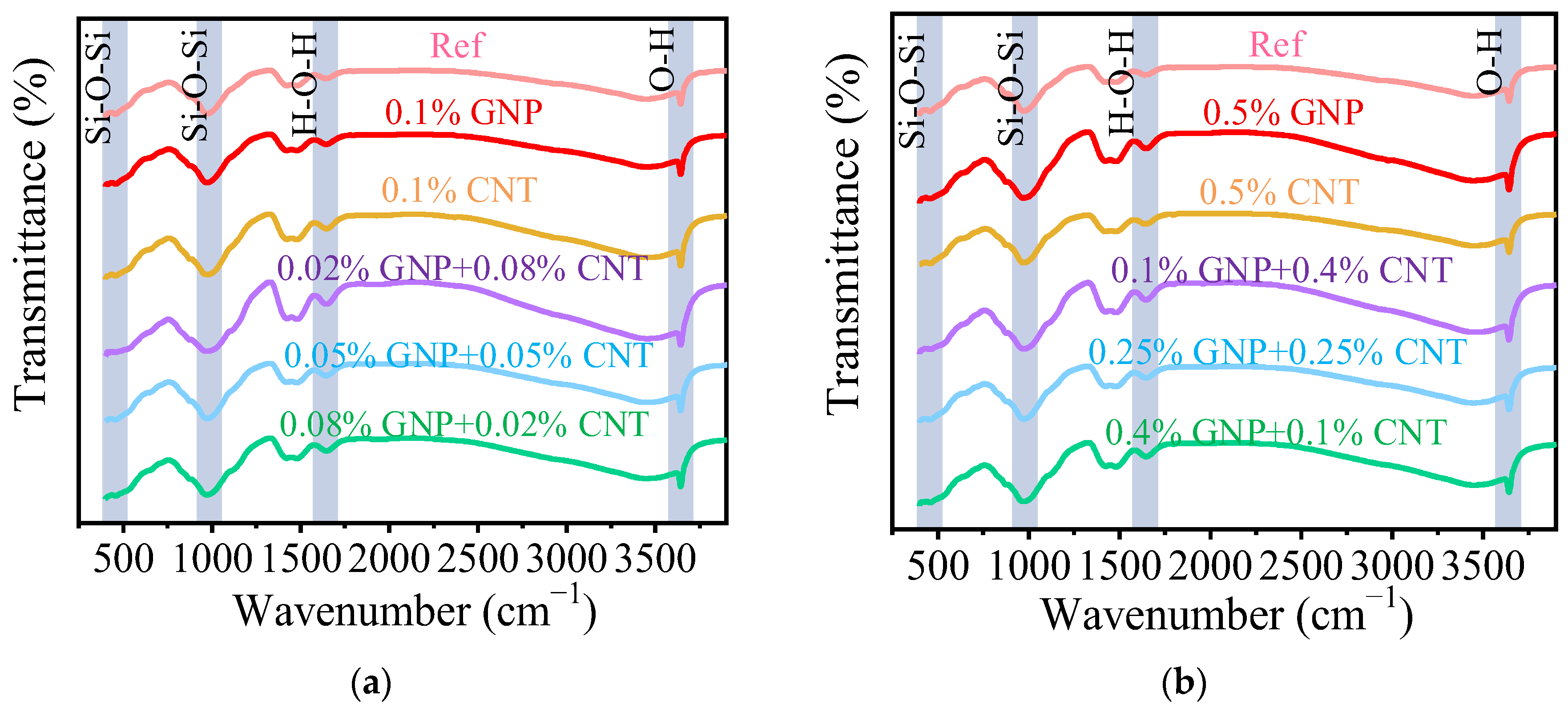
The FTIR analysis results are depicted in Figure 10. The infrared spectra of specimens with different GNP/CNT ratios exhibited a high degree of similarity. Specifically, the absorption peak near 3600 cm−1 is attributed to the O-H stretching vibration in calcium hydroxide. The O-H absorption peak observed at 1600 cm−1 is likely associated with water within the specimens. Characteristic peaks corresponding to hydration products and unhydrated cement particles appear at approximately 500 cm−1 and 1000 cm−1, which are characteristic of O-Si-O stretching vibrations.
Figure 10. Results of FTIR: (a) 0.1% GNP-CNT admixture; (b) 0.5% GNP-CNT admixture.
From Figure 8, Figure 9 and Figure 10, the addition of GNP and CNT does not apparently change the chemical composition of cement-based materials, which are still mainly composed of hydration products and unhydrated particles. Meanwhile, the promoting effect on cement hydration is also limited, and there is no difference from the control group. Therefore, the physical actions between GNP, CNT, and the cement matrix plays a dominant role in influencing the mechanical and piezoresistive properties.

3.4. Pore Structure Analysis

The pore characteristics of the GNP-CNT cement mortars are shown in Table 5. When the total addition is 0.1% (GNP-CNT admixtures), the porosity increases slightly. In contrast, when the total addition reached 0.5%, the porosity showed a decreasing trend, and with the CNT content, the porosity further decreased. This is because CNTs easily agglomerate—less CNT reduces agglomeration, thus further lowering porosity. Notably, the addition of GNP and CNT induced fluctuations in both mean pore size and threshold pore size. Specifically, for the mixture with 0.25% GNP and 0.25% CNT, concurrent reductions in porosity, mean pore size, and threshold pore size are observed. Overall, the addition of 0.25% GNP combined with 0.25% CNT exerted a favorable influence on the pore structure of all specimens.
Table 5. Representative MIP results of GNP-CNT nanoengineered composites.
Figure 11 displays the accumulative and differential pore size distributions of GNP-CNT cement mortars derived from MIP tests. As evident from the figure, within the pore size range of 10–40 nm, a rapid increase in mercury intrusion volume is observed, indicating the formation of an interconnected pore network, called threshold pore size []. Furthermore, when the relative contents of GNP and CNT are unequal, the pore size distribution curves moved right, indicating an increase in the pore size. In contrast, when GNP and CNT are added in equal proportions, the reduction in pore size, which enhances material performance, including improved mechanical strength, durability, and reduced permeability. Particularly at a total addition of 0.5%, the threshold pore size decreases from 17.1 nm to 13.7 nm (Table 5), and the pore volume within the 20–40 nm range is reduced compared to other groups. These results collectively demonstrate that the addition of 0.25% GNP and 0.25% CNT effectively reduces the pore size.
Figure 11. Pore size distribution and cumulative pore size distribution curves of the cement paste modified by GNP and CNT: (a) differential and (b) accumulative pore size distributions of 0.1% GNP-CNT admixture; (c) differential and (d) accumulative pore size distributions of 0.5% GNP-CNT admixture.
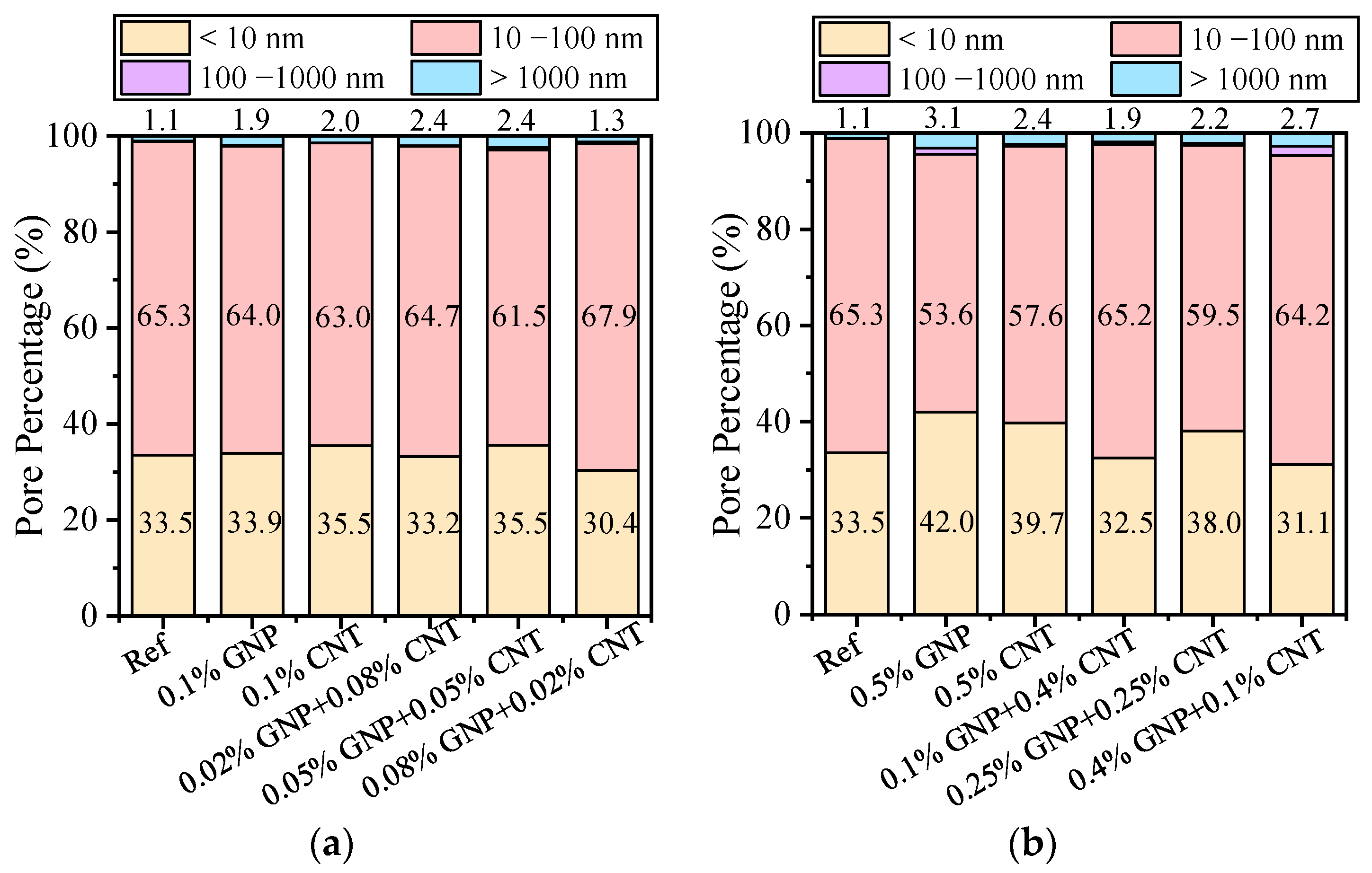
The pores were categorized into four classes: micropores (<10 nm), thin capillary pores (10–100 nm), coarse capillary pores (100–1000 nm), and voids or gaps (>1000 nm). For all samples, the proportions of coarse capillary pores as well as voids or gaps were negligible, accounting for less than 3% (Figure 12). In contrast, thin capillary pores (10–100 nm) were the most dominant, with a proportion of approximately 60%, followed by micropores, which accounted for more than 30%. From the addition of nanomaterials could refine the pore size and optimize the microstructure of the cement-based material. This effect is more pronounced when the total amount of added nanomaterials is relatively large (0.5%), as illustrated in Figure 11c. However, when the GNP/CNT ratio is high, the pore size fails to be refined, which may be attributed to the sheet-like structure of GNPs and their high content, leading to the interfacial gaps and agglomeration.
Figure 12. The pore percentage distribution from MIP analysis: (a) 0.1% GNP-CNT admixture; (b) 0.5% GNP-CNT admixture.

3.5. Microstructure

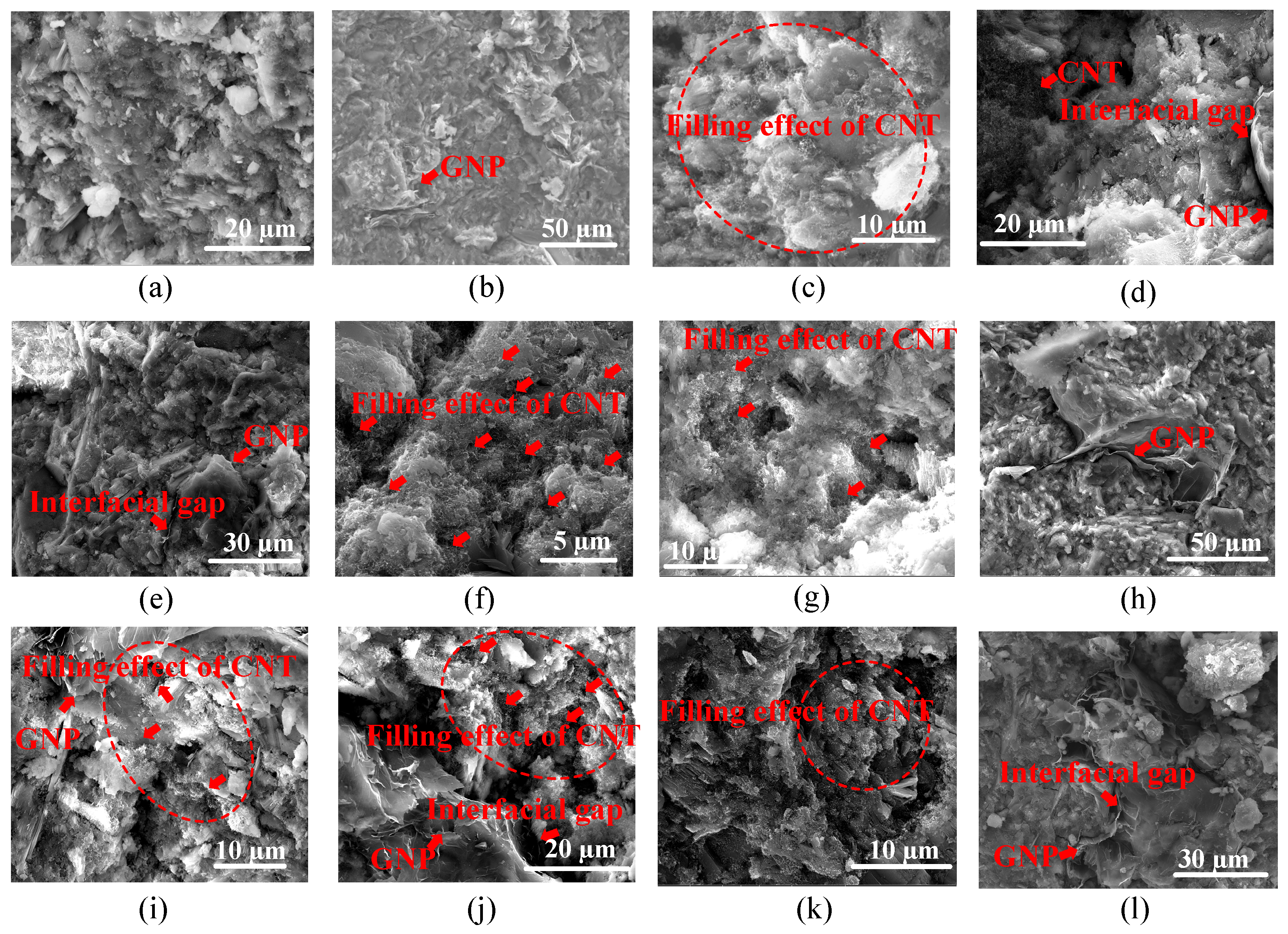
The microscopic morphology of CNT-GNP cement-based materials is presented in Figure 13. It is observed that the hydration products in all specimens are uniformly distributed with a dense structure, and individual or agglomerated forms of GNP and CNT embedded within the cement slurry matrix can be clearly identified. Furthermore, the size of GNP is larger than that of CNT (Figure 13d,i,j), which existed in a multi-layered overlapping state without obvious agglomeration (Figure 13b,h,l), maintaining uniform dispersion in the cement matrix even when its content is increased to 0.5%. Due to their small diameter and super aspect ratio, CNTs are prone to entanglement, forming clustered agglomerations that tend to accumulate at the pores of hydration products (Figure 13c,f–k). Additionally, when GNP and CNT are mixed, they remain spatially separated without mutual contact or entanglement, thus avoiding the formation of larger agglomerates (Figure 13d,i,j). Both GNP and CNT exhibit a pore-filling effect in the matrix, due to the smooth surface of GNPs, a distinct interfacial gap (Figure 13d,e,j,l) is observed between GNPs and the surrounding hydration products.
Figure 13. Typical SEM pictures of the cement paste modified by nanocarbon materials: (a) Ref; (b) 0.5% GNP; (c) 0.5% CNT; (d) 0.02% GNP + 0.08% CNT; (e) and (f) 0.05% GNP + 0.05% CNT; (g) and (h) 0.08% GNP + 0.02% CNT; (i) 0.1% GNP + 0.4% CNT; (j) 0.25% GNP + 0.25% CNT; (k,l) 0.4% GNP + 0.1% CNT.

4. Discussion

The piezoresistive performance of materials is associated with their structure, composition, and interfacial interactions [,]. Under external loading, resistivity variation primarily arises from two parts []: one is the change in the material’s geometric dimensions [], which follows the classical elasticity theory; the other is the material’s piezoresistive effect [], which is related to interactions between conductive fillers and the insulating matrix. Previous studies [] have indicated that filler effects and interfacial effects play a decisive role in the piezoresistive effect of composite materials.
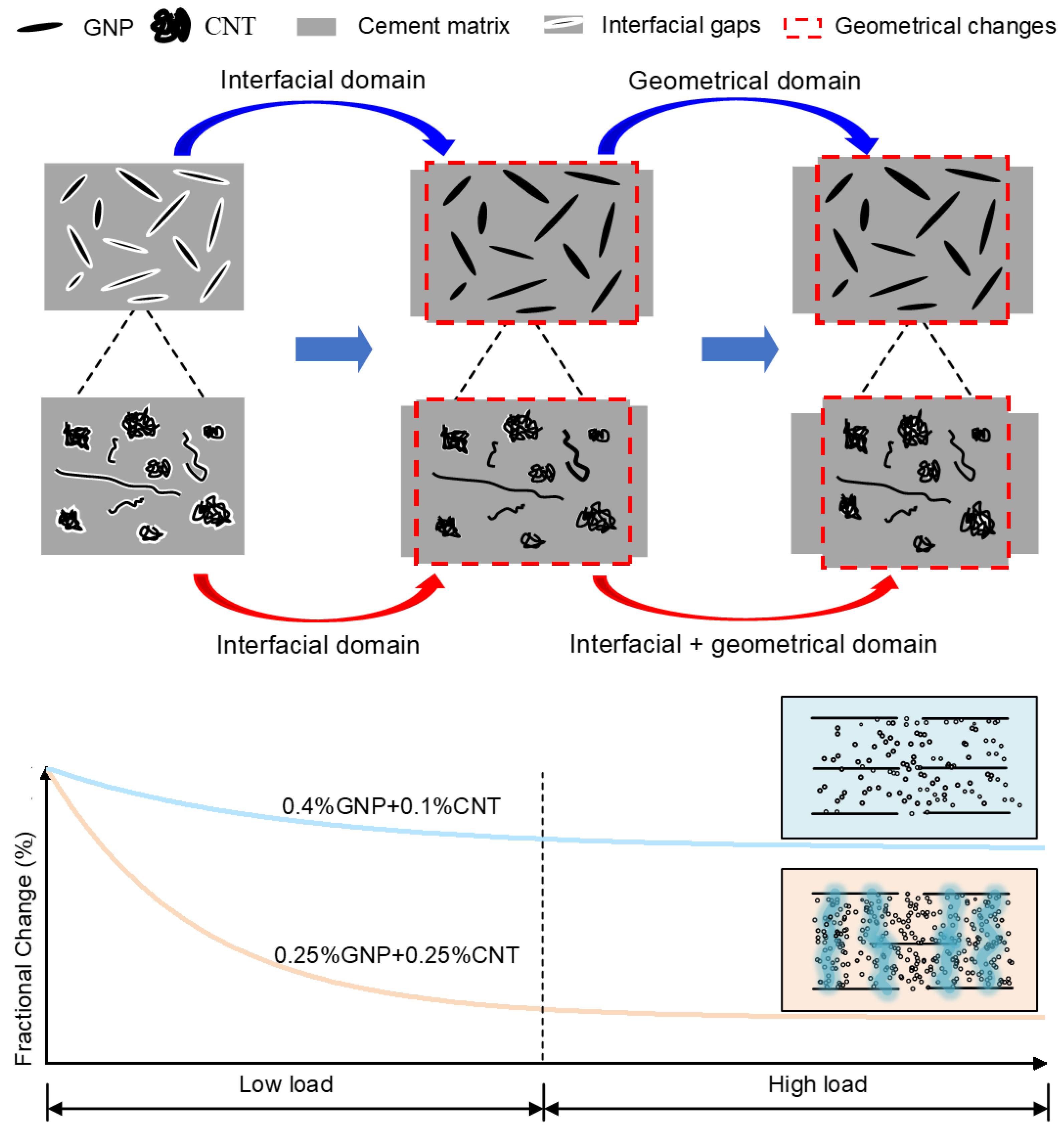
As shown in Figure 14, for GNP in the GNP-CNT nanoengineered composites, the interfacial effect [] dominates under low stress, which enhances interfacial conductivity, reduces the material’s electrical resistivity, and leads to a rapid increase in the electrical resistivity change rate (Figure 5, Figure 6 and Figure 7). Herein, the interface refers to gaps between GNPs and the matrix [], which are caused by the wrinkling or bending of GNPs. In contrast, under high stress, the geometric dimensions of the cement matrix play a dominant role. However, owing to the high electrical conductivity of GNPs, conductive pathways [] have already formed and are insensitive to geometric distance. Consequently, the material’s electrical resistivity remains unchanged under high loads (sample 0.1% GNP and 0.5% GNP in Figure 7). For CNT in the GNP-CNT nanoengineered composites, the interfacial effect also dominates under low stress. These interfacial gaps are the first to close, which in turn improves interfacial conductivity and raises the electrical resistivity change rate. However, numerous tiny gaps or pores at the interface between CNTs and the cement matrix are not fully closed under low stress (Figure 14). When the cement-based materials are subjected to high load, these gaps or pores close, thereby preserving interfacial effects even under high-stress conditions. Therefore, CNTs exhibit favorable piezoresistive performance at any stress (sample 0.1% CNT and 0.5% CNT in Figure 7), with an approximately linear relationship between the electrical resistivity change rate and stress. This explains why the GNP-CNT nanoengineered composites demonstrate superior piezoresistive performance throughout the stress range—specifically (Figure 14), it is attributed to the synergistic effect of the respective functions of CNTs and GNPs.
Figure 14. Mechanisms for piezoresistive responses to stresses.
A more detailed explanation of how varying GNP/CNT ratios affect the resistive performance is provided in Figure 14. When the contents of GNPs and CNTs in the cement-based matrix are equal—taking the 0.25% GNP + 0.25% CNT as an example—CNTs and GNPs can form conductive pathways, as illustrated in the green-colored region. In contrast, when their contents are unequal (e.g., the 0.4% GNP + 0.1% CNT), CNTs and GNPs may fail to establish such conductive networks, resulting in a lower change rate of resistivity.
In addition, several aspects still warrant in-depth investigation in future research. First, it is necessary to explore more efficient dispersion techniques for GNP-CNT admixtures, which could enhance the electrical conductivity and reduce internal porosity of cement-based materials. Second, although the sample with equal GNP and CNT contents exhibits the optimal electrical conductivity among the tested groups, whether a more suitable GNP/CNT ratio exists to achieve superior performance remains to be verified through additional experimental studies.

5. Conclusions

In this study, GNP and CNT with varying contents were added into cement-based materials to tune the synergistic mechanical strength, microstructures, and piezoresistive properties of the composite materials. The key findings are summarized as follows:
GNP and CNT exhibited filling effect, and they interacted with the cement matrix through physical interactions, without altering the phase of the material. The proportion of the GNP-CNT admixture exerts a relatively minor influence on the total porosity of the matrix, with the variation in total porosity not exceeding 1%. Furthermore, distinct ratios of GNPs to CNTs lead to significantly different threshold pore sizes—reaching up to 40 nm—whereas an equal ratio of GNPs to CNTs results in a smaller threshold pore size of approximately 17 nm.
In compressive and flexural strength tests, the admixture of GNP and CNT at a specific proportion led to a slight reduction in compressive strength but a significant increase in flexural strength. Moreover, with increasing total content, the flexural strength was substantially enhanced at any relative GNP/CNT ratios. When the total addition reached 0.5%, the flexural strength increased by over 30%.
The addition of CNT significantly improved the linearity of the material’s piezoresistive performance, enabling the composites to exhibit distinct resistivity changes even under high-stress test conditions. This phenomenon may be attributed to the formation of numerous tiny gaps or pores at the interface between CNT and the cement matrix, which do not fully close under low stress. The study further reveals that when the contents of GNPs and CNTs in the cement matrix are equal, the composite exhibits the high change rate in electrical resistivity among samples, reaching up to 20% (i.e., 0.25% GNPs + 0.25% CNTs).

Author Contributions

Conceptualization, J.T. and Q.Z.; Methodology, K.T., Y.Z., J.W., J.T. and Q.Z.; Formal analysis, H.Y. and J.T.; Investigation, J.T.; Resources, K.T., Y.Z. and J.W.; Writing—original draft, Haiyan Yang; Writing—review & editing, Q.Z.; Supervision, K.T., Y.Z., J.W. and Q.Z.; Project administration, K.T., Y.Z. and J.W. All authors have read and agreed to the published version of the manuscript.

Funding

This work was supported by ZJU-ZCCC Institute of Collaborative Innovation Project No. ZDJG2021008.

Data Availability Statement

The original contributions presented in this study are included in the article. Further inquiries can be directed to the corresponding author.

Acknowledgments

The authors express sincere gratitude for the editors and reviewers.

Conflicts of Interest

Authors Kebiao Tu and Junjian Wang were employed by the company Zhejiang Tongtu Traffic Engineering Co., Ltd. Author Yeqing Zhang was employed by the company Tongshun Greening and Landscape Engineering Co., Ltd. The remaining authors declare that the research was conducted in the absence of any commercial or financial relationships that could be construed as a potential conflict of interest.

Appendix A

The remaining plots illustrating the relative (fractional) changes in electrical resistivity with applied stress, along with their corresponding fitting curves, are shown in Figure A1.
Figure A1. Relative (fractional) changes in electric resistivity with stress and fitting curves: (a) 0.1% GNP; (b) 0.1% CNT; (c) 0.02% GNP + 0.08% CNT; (d) 0.05% GNP + 0.05% CNT; (e) 0.08% GNP + 0.02% CNT; (f) 0.1% GNP + 0.4% CNT; (g) 0.4% GNP + 0.1% CNT.

References

  1. Han, B.; Guan, X.; Ou, J. Electrode design, measuring method and data acquisition system of carbon fiber cement paste piezoresistive sensors. Sens. Actuators A-Phys. 2007, 135, 360–369. [Google Scholar] [CrossRef]
  2. Wen, S.; Chung, D.D.L. Carbon fiber-reinforced cement as a strain-sensing coating. Cem. Concr. Res. 2001, 31, 665–667. [Google Scholar] [CrossRef]
  3. Taha, M.M.R.; Shrive, N.G. Enhancing fracture toughness of high-performance carbon fiber cement composites. ACI Mater. J. 2001, 98, 168–178. [Google Scholar] [CrossRef] [PubMed]
  4. Wen, S.; Chung, D.D.L. Partial replacement of carbon fiber by carbon black in multifunctional cement–matrix composites. Carbon 2007, 45, 505–513. [Google Scholar] [CrossRef]
  5. Soroushia, P.; Nagi, M.; Okwuegbu, A. Freeze-thaw durability of lightweight carbon fiber reinforced cement composites. ACI Mater. J. 1992, 89, 491–494. [Google Scholar] [CrossRef]
  6. Sanchez, F.; Zhang, L.; Ince, C. Multi-scale performance and durability of carbon nanofiber/cement composites. In Nanotechnology in Construction 3; Springer: Berlin/Heidelberg, Germany, 2009; pp. 345–350. [Google Scholar]
  7. Chung, D.D.L. Cement reinforced with short carbon fibers: A multifunctional material. Compos. Part B-Eng. 2000, 31, 511–526. [Google Scholar] [CrossRef]
  8. Wijesinghe, K.A.P.; Lanarolle, G.; Gunasekara, C.; Hidallana-Gamage, H.D.; Law, D.W.; Wang, L.; Gamage, N.; Gunathilaka, H.M.B.I. Thermal insulation and acoustic absorption performance of textile fibre-reinforced cement mortars. J. Build. Eng. 2025, 111, 113128. [Google Scholar] [CrossRef]
  9. Akbar, A.; Kodur, V.K.R.; Liew, K.M. Microstructural changes and mechanical performance of cement composites reinforced with recycled carbon fibers. Cem. Concr. Compos. 2021, 121, 104069. [Google Scholar] [CrossRef]
  10. Balandin, A.A.; Ghosh, S.; Bao, W.; Bao, W.; Calizo, I.; Teweldebrhan, D.; Miao, F.; Lau, C. Superior Thermal Conductivity of Single-Layer Graphene. Nano Lett. 2008, 8, 902–907. [Google Scholar] [CrossRef] [PubMed]
  11. Toutanji, H.A.; Elkorchi, T.; Katz, R.N. Strength and reliability of carbon-fiber-reinforced cement composites. Cem. Concr. Compos. 1994, 16, 15–21. [Google Scholar] [CrossRef]
  12. Banthia, N.; Djeridane, S.; Pigeon, M. Electrical resistivity of carbon and steel micro-fiber reinforced cements. Cem. Concr. Res. 1992, 22, 804–814. [Google Scholar] [CrossRef]
  13. Zhu, Y.; Murali, S.; Cai, W.; Li, X.; Suk, J.W.; Potts, J.R.; Ruoff, R.S. Graphene and Graphene Oxide: Synthesis, Properties, and Applications. Adv. Mater. 2010, 22, 3906–3924. [Google Scholar] [CrossRef]
  14. Stoller, M.D.; Park, S.; Zhu, Y.; An, J.; Ruoff, R.S. Graphene-Based Ultracapacitors. Nano Lett. 2008, 8, 3498–3502. [Google Scholar] [CrossRef]
  15. Varillas, J.; Lukeš, J.; Manikas, A.; Maňák, J.; Dluhoš, J.; Melníková, Z.; Kalbáč, M.; Galiotis, C.; Frank, O. Mechanical response of monolayer graphene via a multi-probe approach. Int. J. Mech. Sci. 2024, 273, 109208. [Google Scholar] [CrossRef]
  16. Sevim, O.; Jiang, Z.; Ozbulut, O.E. Effects of graphene nanoplatelets type on self-sensing properties of cement mortar composites. Constr. Build. Mater. 2022, 359, 129488. [Google Scholar] [CrossRef]
  17. Win, T.T.; Raengthon, N.; Prasittisopin, L. Advanced cement composites: Investigating the role of graphene quantum dots in improving thermal and mechanical performance. J. Build. Eng. 2024, 96, 110556. [Google Scholar] [CrossRef]
  18. Abedi, M.; Fangueiro, R.; Correia, A. Development of a Novel Multifunctional Cementitious-Based Geocomposite by the Contribution of CNT and GNP. Nanomaterials 2021, 11, 961. [Google Scholar] [CrossRef]
  19. Tufail, R.; Naeem, M.; Ahmad, J.; Waheed, H.; Majdi, A.; Farooq, D.; Maqsoom, A.; Butt, F. Evaluation of the fresh and mechanical properties of nano-engineered self compacting concrete containing graphite nano/micro platelets. Case Stud. Constr. Mater. 2022, 17, e01165. [Google Scholar] [CrossRef]
  20. Wang, B.; Jiang, R.; Wu, Z. Investigation of the Mechanical Properties and Microstructure of Graphene Nanoplatelet-Cement Composite. Nanomaterials 2016, 6, 200. [Google Scholar] [CrossRef]
  21. Massion, C.; Lu, Y.; Crandall, D.; Bunger, A.; Radonjic, M. Graphene nanoplatelets reinforced cement as a solution to leaky wellbores reinforcing weak points in hydrated Portland cement with graphene nanoparticles improves mechanical and chemical durability of wellbore cements. Cem. Concr. Compos. 2022, 133, 104726. [Google Scholar] [CrossRef]
  22. Du, H.; Pang, S.D. Enhancement of barrier properties of cement mortar with graphene nanoplatelet. Cem. Concr. Res. 2015, 76, 10–19. [Google Scholar] [CrossRef]
  23. Kishore, K.; Pandey, A.; Wagri, N.K.; Saxena, A.; Patel, J.; Al-Fakih, A. Technological challenges in nanoparticle-modified geopolymer concrete: A comprehensive review on nanomaterial dispersion, characterization techniques and its mechanical properties. Case Stud. Constr. Mater. 2023, 19, e02265. [Google Scholar] [CrossRef]
  24. Tao, J.; Wang, X.; Wang, Z.; Zeng, Q. Graphene nanoplatelets as an effective additive to tune the microstructures and piezoresistive properties of cement-based composites. Constr. Build. Mater. 2019, 209, 665–678. [Google Scholar] [CrossRef]
  25. Fan, Y.; Ni, Z.; Mu, S.; Hang, Z.; Wang, Y.; Feng, C.; Su, Y.; Weng, G.J. Hybrid micromechanical modelling and experiments on electrical conductivity of graphene reinforced porous and saturated cement composites. Cem. Concr. Compos. 2023, 141, 105148. [Google Scholar] [CrossRef]
  26. Amiryaghoubi, N.; Fathi, M.; Barar, J.; Omidian, H.; Omidi, Y. Recent advances in graphene-based polymer composite scaffolds for bone/cartilage tissue engineering. J. Drug Deliv. Sci. Technol. 2022, 72, 103360. [Google Scholar] [CrossRef]
  27. Zeng, Y.; Peng, L.; Ma, B.; Sun, W.; Shi, X.; Zou, Z.; Chen, W. Influence of multi-walled carbon nanotubes on the performance of nano-silica enhanced lightweight cement-based composites under cyclic action of freeze-thaw and erosion. Constr. Build. Mater. 2025, 493, 143132. [Google Scholar] [CrossRef]
  28. Xu, S.; Liu, J.; Li, Q. Mechanical properties and microstructure of multi-walled carbon nanotube-reinforced cement paste. Constr. Build. Mater. 2015, 76, 16–23. [Google Scholar] [CrossRef]
  29. Jiříčková, A.; Pavlík, Z.; Pavlíková, M.; Pivák, A.; Záleská, M.; Lauermannová, A.M.; Jankovský, O. Impact of oxidized carbon nanotubes on the mechanical, thermal, and hygric properties of Portland cement- and magnesium oxychloride cement-based mortars: A route to advanced building composites. Case Stud. Constr. Mater. 2025, 22, e04902. [Google Scholar] [CrossRef]
  30. Han, B.; Yu, X.; Kwon, E. A self-sensing carbon nanotube/cement composite for traffic monitoring. Nanotechnology 2009, 20, 445501. [Google Scholar] [CrossRef]
  31. Li, W.W.; Ji, W.M.; Wang, Y.C.; Liu, Y.; Shen, R.X.; Xing, F. Investigation on the Mechanical Properties of a Cement-Based Material Containing Carbon Nanotube under Drying and Freeze-Thaw Conditions. Materials 2015, 8, 8780–8792. [Google Scholar] [CrossRef]
  32. Elena, C.P.; Rosalía, P.T.; Fernando, V. Effect of Multi-Walled Carbon Nanotubes on Strength and Electrical Properties of Cement Mortar. Materials 2021, 14, 79. [Google Scholar]
  33. Cui, H.; Yang, S.; Memon, S. Development of Carbon Nanotube Modified Cement Paste with Microencapsulated Phase-Change Material for Structural–Functional Integrated Application. Int. J. Mol. Sci. 2015, 16, 8027–8039. [Google Scholar] [CrossRef]
  34. Habib, A.; Maalej, M.; Dirar, S.; Junaid, M.T.; Altoubat, S. Sensitive Analysis on the Compressive and Flexural Strength of Carbon Nanotube-Reinforced Cement Composites Using Machine Learning. SDHM Struct. Durab. Health Monit. 2025, 19, 789–817. [Google Scholar] [CrossRef]
  35. Jia, X.; Anna Lushnikova, A.; Plé, O. Use of Carbon Nanotubes for the Functionalization of Concrete for Sensing Applications. Sensors 2025, 25, 3755. [Google Scholar] [CrossRef]
  36. Saafi, M. Wireless and embedded carbon nanotube networks for damage detection in concrete structures. Nanotechnology 2009, 20, 395502. [Google Scholar] [CrossRef]
  37. Zhou, L.; Li, J.; Xing, C. MXene–polymer nanocomposites for precise structural and functional applications. Chem. Eng. J. 2025, 506, 159868. [Google Scholar] [CrossRef]
  38. Tjong, S.C. Recent progress in the development and properties of novel metal matrix nanocomposites reinforced with carbon nanotubes and graphene nanosheets. Mater. Sci. Eng. R 2013, 74, 281–350. [Google Scholar] [CrossRef]
  39. GB/T 17671-1999; Method of Testing Cement Mortar Strength. China Building Materials Press: Beijing, China, 1999.
  40. Mironov, V.S.; Kim, J.K.; Park, M.; Lim, S.; Cho, W.K. Comparison of electrical conductivity data obtained by four-electrode and four-point probe methods for graphite-based polymer composites. Polym. Test. 2007, 26, 547–555. [Google Scholar] [CrossRef]
  41. Islam, I.; Chng, H.K.; Yap, A.U. X-ray diffraction analysis of mineral trioxide aggregate and Portland cement. Int. Endod. J. 2010, 39, 220–225. [Google Scholar] [CrossRef]
  42. Zuaiter, M.; Al-Rub, R.K.A.; Banat, F.; Kim, T.Y. Bio-derived sustainable graphene alternative for enhancing the mechanical properties of cement mortars. Constr. Build. Mater. 2025, 489, 142245. [Google Scholar] [CrossRef]
  43. Zhang, Q.; Zeng, Q.; Zheng, D.; Wang, J.; Xu, S. Oven dying kinetics and status of cement-based porous materials for in-lab microstructure investigation. Adv. Cem. Res. 2018, 30, 204–215. [Google Scholar] [CrossRef]
  44. Hughes, T.L.; Methven, C.M.; Jones, T.G.J.; Pelham, S.E.; Fletcher, P.; Hall, C. Determining cement composition by Fourier transform infrared spectroscopy. Adv. Cem. Based Mater. 1995, 2, 91–104. [Google Scholar] [CrossRef]
  45. Kim, G.; Suh, H.; Cho, S.; Im, S.; Nezhad, E.; Seok, S.; Choi, C.; Bae, S. Synergistic strengthening mechanism of Portland cement paste reinforced by a triple hybrid of graphene oxide, functionalized carbon nanotube, and nano-silica. Constr. Build. Mater. 2022, 352, 129017. [Google Scholar] [CrossRef]
  46. Qin, X.; Zhu, S.; Zhang, R. Evaluation of Stabilized Graphite Nanoplatelets: Dispersion Quality and Mechanical Properties of Cement Composites. J. Test. Eval. 2019, 47, 20180482. [Google Scholar] [CrossRef]
  47. Zaheer, M. Mechanical Performance of Cementitious Composites by MWCNTs Addition for Structural Applications. J. Civ. Eng. Constr. 2020, 9, 51–62. [Google Scholar] [CrossRef]
  48. Huang, H.; Teng, L.; Gao, X.; Khayat, K.H.; Wang, F.; Liu, Z. Effect of carbon nanotube and graphite nanoplatelet on composition, structure, and nano-mechanical properties of C-S-H in UHPC. Cem. Concr. Res. 2022, 154, 106713. [Google Scholar] [CrossRef]
  49. Konsta-Gdoutos, M.S.; Metaxa, Z.S.; Shah, S.P. Multi-scale mechanical and fracture characteristics and early-age strain capacity of high performance carbon nanotube/cement nanocomposites. Cem. Concr. Compos. 2010, 32, 110–115. [Google Scholar] [CrossRef]
  50. Liu, Y.F.; Hu, Y.G. Piezoresistive behavior of Graphene Oxide/Graphite-modified cement-based composites under combined thermal and tensile effects. Constr. Build. Mater. 2025, 481, 141618. [Google Scholar] [CrossRef]
  51. Dong, W.; Li, W.; Shen, L.; Sun, Z.; Sheng, D. Piezoresistivity of smart carbon nanotubes (CNTs) reinforced cementitious composite under integrated cyclic compression and impact. Compos. Struct. 2020, 241, 112106. [Google Scholar] [CrossRef]
  52. Jing, G.; Ye, Z.; Lu, X.; Hou, P. Effect of graphene nanoplatelets on hydration behaviour of Portland cement by thermal analysis. Adv. Cem. Res. 2016, 29, 63–70. [Google Scholar] [CrossRef]
  53. Zeng, Q.; Mao, T.; Li, H.; Peng, Y. Thermally insulating lightweight cement-based composites incorporating glass beads and nano-silica aerogels for sustainably energy-saving buildings. Energy Build. 2018, 174, 97–110. [Google Scholar] [CrossRef]
  54. Pan, R.; Chen, F.; Feng, Q.; Zeng, Q.; Zhang, Z.; Xu, R. Study on the performance of graphene-enhanced cementitious piezoresistive sensors in self-sensing concrete members. Sens. Actuators A-Phys. 2025, 395, 117050. [Google Scholar] [CrossRef]
  55. Zhang, J.; Wei, S.; Shang, C.; Duan, Y.; He, Z.; An, H.; Yu, X.; Peng, Z. Modeling and experimental analysis of piezoresistive behavior in conductive porous elastomer under significantly large deformation. Int. J. Eng. Sci. 2024, 201, 104091. [Google Scholar] [CrossRef]
  56. Cai, J.; Chawla, S.; Naraghi, M. Piezoresistive effect of individual electrospun carbon nanofibers for strain sensing. Carbon 2014, 77, 738–746. [Google Scholar] [CrossRef]
  57. Goutier, M.; Hilbig, K.; Vietor, T.; Böl, M. Process Parameters and Geometry Effects on Piezoresistivity in Additively Manufactured Polymer Sensors. Polymers 2023, 15, 2159. [Google Scholar] [CrossRef]
  58. Lebedev, O.V.; Ozerin, A.N.; Abaimov, S.G. Multiscale Numerical Modeling for Prediction of Piezoresistive Effect for Polymer Composites with a Highly Segregated Structure. Nanomaterials 2021, 11, 162. [Google Scholar] [CrossRef]
  59. Liu, Y.; Yang, T.; Zhang, B.; Williams, T.; Lin, Y.T.; Li, L.; Zhou, Y.; Lu, W.; Kim, S.H.; Chen, L.Q.; et al. Structural Insight in the Interfacial Effect in Ferroelectric Polymer Nanocomposites. Adv. Mater. 2020, 32, e2005431. [Google Scholar] [CrossRef]
  60. Sun, Q.; Luo, S.; Lin, Y.; Yan, X.; Huang, R.; Liu, Q.; Yan, S.; Lin, X. Interfacial electric field effects enhance the kinetics and stability of magnesium metal anodes for rechargeable magnesium batteries. Adv. Powder Mater. 2025, 4, 100335. [Google Scholar] [CrossRef]
  61. Romain, M.; Roman, P.; Saviot, L.; Millot, N.; Boireau, W. Inferring the Interfacial Reactivity of Gold Nanoparticles by Surface Plasmon Resonance Measurements. Langmuir 2023, 39, 13058–13067. [Google Scholar] [CrossRef]
  62. Zhang, Y.; Xia, W.; Wang, D.; Jiang, Z.; Wang, X.; Dong, M.; Chen, K. Highly stretchable, self-healing, anti-freezing, and moisturizing hydrogel with efficient conductive pathways for self-powered sensing skin electronics. Chem. Eng. J. 2025, 520, 165986. [Google Scholar] [CrossRef]
Disclaimer/Publisher’s Note: The statements, opinions and data contained in all publications are solely those of the individual author(s) and contributor(s) and not of MDPI and/or the editor(s). MDPI and/or the editor(s) disclaim responsibility for any injury to people or property resulting from any ideas, methods, instructions or products referred to in the content.

Article Metrics

Citations

Article Access Statistics

Multiple requests from the same IP address are counted as one view.