Abstract
Fire hazard presents a critical challenge to the structural reliability of underground modular infrastructure. This study examines the fire resistance performance of prefabricated monolithic utility tunnels featuring longitudinal threaded connections. A series of fire exposure tests was conducted on assembled utility tunnel specimens using different bolt materials and thermal conditions, enabling evaluation of fire behavior, deformation behavior, and residual capacity. The observed thermal properties revealed significant temperature gradients across tunnel sections, with the peak internal–external differential reaching 536.8 °C. Post-fire mechanical degradation was evident in reduced stiffness and ductility, and the residual load-bearing capacity declined by up to 12.28% compared to unexposed specimens. Specimens using high-strength threaded bolts demonstrated superior performance compared to stainless steel bolt specimens, exhibiting a 4.67% higher residual capacity and 13.87% less residual deformation. A sequential thermal–mechanical finite element model was developed and calibrated based on experimental results, offering a reliable simulation framework for investigating fire-induced damage and residual strength in modular utility tunnel systems. These findings provide a quantitative basis for fire safety assessment.
1. Introduction
With the continued expansion of urban infrastructure, integrated underground utility tunnels have become an increasingly adopted solution for the centralized installation of municipal lifeline systems, including electricity, telecommunications, gas, water supply, and drainage. These corridors enhance space efficiency, reduce surface disruptions, and enable more effective long-term infrastructure management. By consolidating multiple pipelines into a shared enclosure, utility tunnels significantly decrease the frequency of road excavations, thereby minimizing traffic congestion and improving coordination during urban development projects [1,2,3].
As underground infrastructure becomes more densely constructed, fire hazards within utility tunnels have raised growing safety concerns [4,5,6]. Due to their enclosed and compact geometry, these tunnels tend to trap heat and smoke once a fire breaks out, which can result in steep internal temperature rises and localized thermal intensification. This condition may promote secondary ignition of adjacent materials and severely damage internal utility systems [7,8]. Moreover, the limited accessibility of such confined spaces complicates emergency inspection and firefighting efforts, further escalating the risk of structural failure [9]. Fire exposure significantly degrades the mechanical and thermal properties of concrete and steel [10,11,12,13], resulting in reductions in load-bearing capacity, stiffness, and potentially causing structural instability or collapse, with serious implications for public safety and urban functionality.
Numerous studies have investigated fire behavior in underground structures, focusing on temperature distribution, smoke propagation, ventilation effects, and evacuation strategies [14,15,16,17]. For instance, Vauquelin et al. [18] conducted combustion tests on a scaled utility tunnel model to examine smoke movement and the influence of exhaust outlet geometry and ventilation systems on fire dynamics. Liu et al. [19] performed small-scale fire experiments in enclosed galleries and noted that standard ceiling temperature models—originally developed for open road tunnels—are inadequate for confined utility tunnels, proposing a revised prediction formula. Ingason et al. [20] analyzed thermal and smoke transport through both full-scale and reduced-scale fire experiments in the Rune Hamar tunnel, evaluating temperature fields, visibility, and toxic gas generation.
More recently, research has increasingly focused on the structural response of underground systems under combined thermal and mechanical loading. Lin et al. [21] observed crack formation, surface spalling, and deformation in scaled reinforced concrete tunnel models exposed to fire. Feist et al. [22] developed a coupled thermal–mechanical damage model for reinforced concrete to predict the degradation of fire resistance and residual capacity in tunnel linings. Yan et al. [23] and Shen et al. [24] investigated stress redistribution and failure mechanisms in shield tunnel structures under fire, offering insights into the coupled behavior of underground systems at elevated temperatures.
However, most of this research has focused on transportation tunnels, such as shield and highway tunnels. In contrast, utility tunnels typically feature narrow cross-sections, sealed ends, and internal compartments—resulting in distinct fire dynamics and structural responses [25]. These differences highlight the need for targeted studies on fire-induced damage and post-fire performance in utility tunnel structures.
Prefabricated construction has become prevalent in utility tunnel projects, making joint performance a critical factor in overall structural reliability [26]. Previous studies have shown that joints are often the weakest components in modular systems, where bolt material, layout, and interface detailing significantly affect stiffness, ductility, and failure modes [27,28,29]. To enhance joint behavior, Xue et al. [30] introduced cast-in-place slabs for improved integrity and waterproofing. Ding et al. [31] identified three distinct behavioral stages in full-scale joint tests under combined loading, with shear force notably reducing bending capacity. Liu et al. [32] further confirmed that structural failure was primarily governed by joint behavior, and proper bolt configuration greatly improved global performance. Recent work by Zhang et al. [33] proposed a novel prefabricated integral utility tunnel using mortise–tenon joints and composite slabs, and validated its structural behavior through full-scale static tests and numerical simulation. Their findings further confirm the feasibility of optimized joint detailing in improving the load-bearing capacity and deformation control of assembled tunnel systems.
Although the structural behavior of prefabricated utility tunnels has been increasingly studied, the fire performance of their joint systems—particularly under post-fire conditions—remains underexplored. Key issues such as thermal stability, crack evolution, stress redistribution, and residual mechanical capacity have yet to be systematically addressed. In particular, few studies have compared the post-fire performance of connections using different bolt materials (e.g., stainless steel vs. high-strength steel).
To bridge these gaps, this study conducts an integrated experimental and numerical investigation into the thermo-mechanical behavior of prefabricated utility tunnels assembled with longitudinal threaded bolt joints. Fire tests and validated finite element models are used to evaluate temperature distribution, crack propagation, stress development, and post-fire strength degradation under varied thermal and connection conditions. Special emphasis is placed on contrasting the structural response between stainless steel and high-strength bolt assemblies. The obtained data enable evaluation of fire-induced degradation in structural performance of utility tunnels, including internal temperature gradients, deformation development, and residual bearing capacity, which form essential indicators for structural fire safety assessment.
To further clarify the research scope and highlight the distinct contributions of this study, a comparative summary of recent tunnel fire investigations is presented in Table 1. The table provides a brief comparison of previous studies on highway, metro, and shield tunnels with the present work in terms of fire-related focus and structural concerns. It underscores that this study concentrates on the mechanical performance of prefabricated utility tunnels under fire, particularly the influence of different bolt materials—a subject that has received limited attention in existing research.

Table 1.
Summary of representative studies on tunnel under fire and focus of the present study.
2. Experimental Program
This study investigates the degradation of mechanical performance in prefabricated modular utility tunnel segments subjected to fire exposure. Three utility tunnel specimens were designed and fabricated, with key test variables including fire exposure condition (exposed vs. unexposed) and bolt connection type (stainless steel vs. high-strength bolts). For fire-exposed specimens, the standard temperature–time curve defined in ISO 834-1:2025 [34] was applied to simulate thermal loading, followed by post-fire static loading tests. This standardized curve was selected to ensure consistency with widely used structural fire testing protocols and to facilitate controlled and repeatable experimental conditions. The objective was to evaluate variations in stiffness and residual load-bearing capacity under different thermal environments and connection configurations. The following subsections describe the specimen details, fire simulation procedures, loading protocols, and observation methods.
2.1. Specimen Details
The tunnel specimens were designed based on real urban utility tunnel structures commonly used in Chinese municipal engineering. A 1:3 scale ratio was selected according to NFPA 92 guidelines [35] and similarity theory. The model design satisfied geometric, material, and thermal similarity criteria. The scaled model design methodology was developed with reference to previous studies on mechanical and fire performance tests of utility tunnels conducted by other scholars [5,36,37,38,39], in which scale ratios between 1:2 and 1:6 were commonly adopted and widely recognized.
Geometric similarity ensures proportional relationships in length, area, and displacement between the model and the prototype. Material similarity is achieved by using the same concrete and reinforcement steel, thereby maintaining equal elastic modulus and stress–strain behavior. Load similarity was preserved by matching surface loads and fire temperatures, while boundary similarity considers the absence of lateral soil pressure and the simplified vertical loading. For thermal similarity, the heating duration and temperature evolution followed ISO 834-1:2025 [34], ensuring comparable thermal input and response timing.
To illustrate this further, a similarity constant table (Table 2) was introduced, summarizing the dimensionless relationships among key physical parameters. For example, reinforcement design followed the equal-strength principle to maintain consistent stress transfer across scales, using proportional relationships between steel and concrete areas and strengths in both model and prototype.

Table 2.
Similarity constant of prefabricated utility tunnel model.
Due to the inherent complexity of fire phenomena, it is not feasible to achieve complete similarity for all variables. As such, this study prioritizes key similarity criteria and reasonably relaxes secondary factors to balance accuracy and feasibility. It is also noted that, according to NFPA 92 [35], fire experiments with geometric scales smaller than 1:8 suffer from poor similarity accuracy. Thus, a 1:3 scale was selected as a practical compromise to ensure both test safety and reliability.
It should be noted that thermal responses in scaled models may differ from full-scale structures due to reduced thermal inertia and imperfect scaling of heat conduction. In actual tunnels, the larger mass and volume may delay peak temperatures and produce more heterogeneous thermal fields. Therefore, the observed gradients in the scaled tests may represent an upper-bound condition.
A total of six prefabricated tunnel segments were fabricated and assembled into three test specimens. Each tunnel segment measured 500 mm in length and 1200 mm in both width and height, with a slab thickness of 120 mm. The concrete used was of strength grade C40, and the reinforcement consisted of HRB400 steel bars with a diameter of 10 mm. As shown in Figure 1, rectangular cavities (100 mm × 80 mm × 80 mm) were pre-configured at the haunch connections of each segment. Bolt channels (20 mm diameter) were reserved to facilitate installation of either stainless steel or high-strength bolts, which were used to assemble two single-panel segments into a double-unit utility tunnel specimen. The structural layout and reinforcement details are illustrated in Figure 2, while key specimen parameters are summarized in Table 3.

Figure 1.
Configuration of bolt cavities and assembly layout of prefabricated utility tunnels.
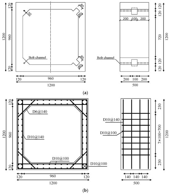
Figure 2.
The utility tunnel segment: (a) detailed structural dimensions, and (b) reinforcement arrangement.

Table 3.
Specimen details.
The fabrication process included formwork installation, reinforcement binding, bolt hole reservation, concrete casting, curing, transportation, and final assembly, as illustrated in Figure 3. Among the specimens, UTBC1 and UTBF2 were assembled using stainless steel bolts, while UTFH3 used high-strength bolts. The two bolt types are depicted in Figure 1.

Figure 3.
The fabrication process of the utility tunnel specimens.
2.2. Heating and Loading Scheme
The experimental setup consisted of two subsystems: a vertical load application unit simulating backfill pressure and a fire exposure unit simulating high-temperature conditions. A uniformly distributed vertical load was applied using hydraulic jacks and steel load-distribution beams to simulate the overburden pressure of the surrounding soil.
Simultaneously, electric heating panels were mounted at both tunnel end openings using fixed brackets. Ceramic fiber blankets were applied around the interface between heating units and tunnel surfaces to ensure effective thermal insulation and uniform heat transfer. The full setup layout is shown in Figure 4. The fire exposure method simulates thermal propagation within a closed tunnel by applying high-temperature loading to both segment ends, mimicking a more realistic internal fire scenario in utility tunnels.
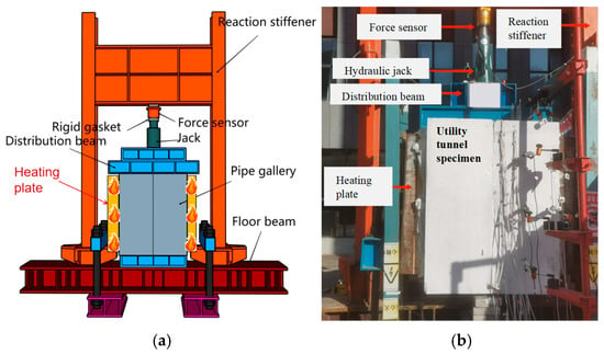
Figure 4.
Heating and loading scheme: (a) schematic diagram, and (b) actual diagram.
As illustrated in Figure 5a, the full-scale utility tunnel is subjected to both vertical overburden pressure and lateral soil pressure. However, due to spatial limitations and equipment constraints in the experimental setup, the loading scheme was simplified to apply only the vertical component. To ensure that this simplification remained both representative and conservative, a comparative structural analysis was conducted based on the closed-frame model.
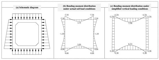
Figure 5.
Comparison of loading conditions and bending moment distributions in utility tunnel cross-sections: (a) actual loading including vertical and lateral soil pressure, (b) internal moment under actual loading, and (c) internal moment under simplified vertical loading.
As shown in Figure 5b,c, the internal bending moment distributions under actual and simplified loading conditions were calculated using SAP2000 (Computers and Structures, Inc., Walnut Creek, CA, USA). Comparison of the moment diagrams reveals that, under identical vertical loading, the mid-span bending moment in the full-load model is only 58% of that in the simplified-load model. This demonstrates that the simplified load scheme yields conservative results with a reasonable safety margin, thereby validating its application in experimental settings.
Accordingly, a vertical load of 70 kN was applied to the top slab of the tunnel in the experiment, corresponding to the estimated soil pressure at a burial depth of 2.5 m. The load calculation considered a soil unit weight of 18 kN/m3, a surface load of 10 kN/m2, and a lateral earth pressure coefficient of 0.5.
As illustrated in Figure 6, the experiment was divided into three sequential stages to simulate realistic thermal–mechanical behavior:
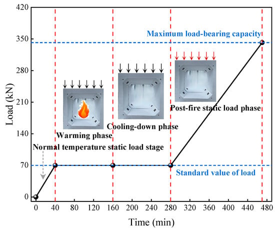
Figure 6.
The experimental loading process.
- (1)
- Static loading at ambient temperature
A vertical load of 70 kN, corresponding to an estimated earth pressure at 2.5 m burial depth, was applied in five equal increments (14 kN each). Each loading stage was held for 5 min to ensure deformation stability. After reaching the full design load, the load was maintained for 20 min under room temperature conditions.
- (2)
- Thermo-mechanical coupling stage
The previously applied static load was maintained while fire loading was introduced using electric heating panels. Heating followed the ISO 834-1:2025 standard fire curve [34] and was sustained for 2 h. After heating, specimens were allowed to cool naturally in ambient air until room temperature was restored.
- (3)
- Post-fire static loading
Once cooled, specimens were subjected to incremental static loading until failure. This stage was designed to assess residual stiffness, load-bearing capacity, and structural degradation following fire exposure.
2.3. Observation Scheme
To comprehensively evaluate the mechanical performance of prefabricated utility tunnels under fire exposure, a combination of thermal, deformation, and failure monitoring techniques was implemented. In addition to residual load-bearing capacity, the temperature distribution, displacement response, and damage evolution were systematically recorded throughout all experimental stages.
As shown in Figure 7, displacement transducers were installed on the top and side walls of the tunnel specimens to monitor real-time deformation throughout the entire fire testing sequence. For thermal measurements, thermocouples were arranged at key locations using a non-uniform distribution strategy to capture localized thermal gradients with higher spatial accuracy.
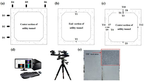
Figure 7.
Measurement Point Layout: (a) displacement transducer arrangement at the center section, (b) thermocouples at the end section, (c) thermocouples at the center section, (d) DIC observation equipment, (e) DIC test area.
Specifically, thermocouples were embedded in the pre-reserved bolt cavities at the top and bottom slabs to monitor temperature evolution around the longitudinal bolt connections. Additional thermocouples were embedded at varying depths within top and side slab cross-sections to capture internal temperature gradients, as illustrated in Figure 7.
Moreover, Digital Image Correlation (DIC) technology was employed to capture full-field surface deformation and crack development during the fire exposure process, as shown in Figure 7. DIC is a non-contact, optical measurement technique based on digital image analysis. By comparing the speckle patterns on the specimen surface before and after deformation, full-field strain distribution and crack propagation mechanisms can be accurately quantified. The DIC system provided high-resolution spatial data on damage initiation and evolution across different fire stages.
3. Test Results and Analysis Under Thermo-Mechanical Coupling
A total of three prefabricated utility tunnel specimens were tested to investigate the structural performance. Among them, specimen UTBC1 served as the control group and was subjected to static loading without fire exposure. In contrast, specimens UTBF2 and UTFH3—connected using stainless steel bolts and high-strength bolts, respectively—were exposed to sustained vertical loading in combination with thermal loading, following the standard ISO 834-1:2025 fire curve [34]. Upon reaching ambient temperature after natural cooling, both fire-exposed specimens were tested to failure under monotonic static loading.
This section presents the thermo-mechanical response of specimens UTBF2 and UTFH3 during the fire exposure stage, with emphasis on the temperature field evolution, deformation behavior, and damage characteristics observed throughout the process. These results form the foundation for subsequent analyses of post-fire residual load-bearing performance.
3.1. Experimental Observations
The thermal–mechanical response of specimens UTBF2 and UTFH3 under combined vertical loading and high-temperature fire exposure is illustrated in Figure 8.
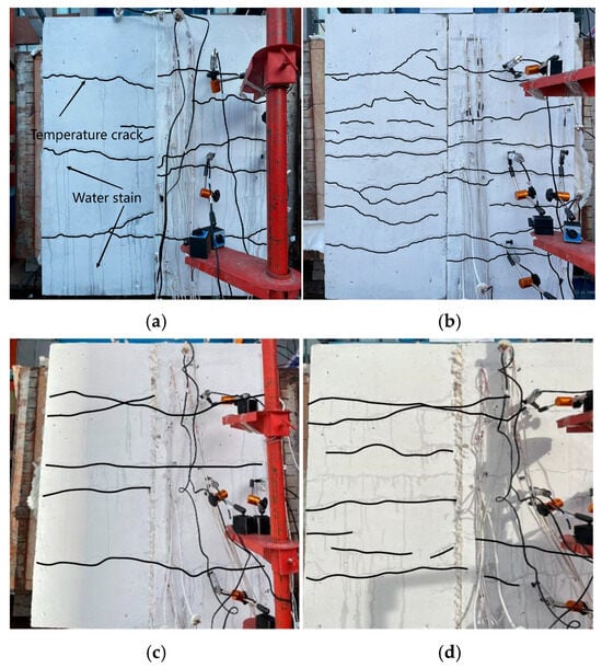
Figure 8.
Test phenomena on the side walls of utility tunnel specimens during thermal–mechanical coupling test: (a) UTBF2 specimen after 60 min heating, (b) UTBF2 specimen after 120 min heating, (c) UTFH3 specimen after 60 min heating, and (d) UTFH3 specimen after 120 min heating.
At the initial loading stage, both specimens remained in the elastic range under a vertical load of 70 kN, simulating soil overburden, with no visible surface damage. Upon fire exposure, moisture evaporation and surface discoloration were observed within the first 10 min. By 20 min, fine cracks initiated at the mid-span of the sidewalls, accompanied by localized water seepage, indicating internal pore pressure buildup. As heating progressed, cracks extended diagonally toward the lower corners, widening progressively after 60 min. By the end of the 120 min ISO 834-1:2025 [34] fire exposure, crack development had largely stabilized, with no significant crack formation.
During natural cooling, partial crack closure was noted due to thermal contraction, alongside coating detachment and minor concrete spalling. Importantly, both stainless steel and high-strength bolts at segment joints showed no visible slippage or thermal failure. Specimens UTBF2 and UTFH3 exhibited similar damage patterns, indicating consistent thermo-mechanical behavior under the given loading and fire conditions.
3.2. Temperature Response Analysis
The internal temperature distribution of the utility tunnel specimens under fire exposure was obtained through thermocouples embedded at key structural locations. Figure 9 presents the temperature profiles along the thickness direction of the top and side slabs for specimens UTBF2 and UTFH3. Specifically, the graphs in Figure 9 correspond to thermocouples placed at representative points along the top and side plates of the tunnel segments (T3, T6, T8, T10 for top plates and T4, T7, T9, T11 for side plates), as defined in the thermocouple layout in Figure 7.


Figure 9.
Temperature gradient changes in concrete cross-sections of various utility tunnels: (a) UTBF2 top plate, (b) UTBF2 side plate, (c) UTFH3 top plate and (d) UTFH3 side plate.
It is evident that the temperature at different positions exhibited a nonlinear increase with heating duration. A significant thermal lag was observed between surface and interior measurement points. Specifically, the surface thermocouples recorded a sharp rise around 10 min, whereas interior points began to increase only after approximately 15 min. This delay can be attributed to the inherent thermal inertia of concrete, which has high specific heat capacity and low thermal conductivity.
All interior measurement points exhibited a clear “temperature plateau” around 90–100 °C, attributed to the endothermic vaporization of free water in the concrete. The duration of this plateau varied with concrete moisture content and distance from the fire-exposed surface. After heating ceased at 120 min, internal temperatures continued to rise briefly due to delayed heat transfer from hotter to cooler regions.
For specimen UTBF2, the maximum temperature on the top slab inner surface (T3) reached 722.9 °C, while embedded sensors at T6 (384.1 °C), T8 (201.2 °C), and T10 (150.1 °C) revealed a steep thermal gradient. A similar trend was observed in the sidewall, with T4 (703.0 °C) near the surface and T11 (122.0 °C) at greater depth. Specimen UTFH3 showed comparable thermal profiles, with a top slab surface temperature of 721.3 °C and an internal peak of 125.1 °C at T10, yielding a vertical temperature difference of 596.2 °C. These observations are consistent with the findings of Liang et al. [40], validating the nonlinear and gradient-based thermal response of concrete under fire exposure.
Longitudinally, temperature–time curves (Figure 10) show that the top slab experienced a 175.3 °C difference between the end (T1) and mid-span (T6), while the bottom slab exhibited a 200.4 °C difference (T2 vs. T5). At each section, top slab temperatures exceeded those of the bottom slab, with vertical differences up to 148.4 °C. These findings confirm a distinct 3D thermal gradient—both longitudinal and vertical—within the tunnel, driven primarily by fire propagation distance rather than bolt material type.

Figure 10.
Longitudinal temperature changes in the concrete of the top and bottom slabs of each tunnel segment: (a) UTBF2 and (b) UTFH3.
3.3. Cumulative Damage Analysis of Concrete
Concrete, as a typical composite material, undergoes not only physical changes such as thermal expansion and moisture evaporation under fire exposure, but also irreversible chemical transformations, including dehydration, dihydroxylation, and mineral phase transitions. Numerous studies [41,42,43,44,45] have demonstrated that the mechanical properties of concrete deteriorate significantly under elevated temperatures, with a sharp drop in normalized residual compressive strength observed beyond 300 °C. Therefore, in this study, 300 °C was adopted as the critical damage evaluation threshold to analyze the thermal field evolution and structural degradation of prefabricated utility tunnels under fire conditions. Multiple thermocouples were embedded at varying depths within the top and side slabs of specimens UTBF2 and UTFH3 to capture temperature profiles at different heating durations. The corresponding thermal distributions are illustrated in Figure 11.
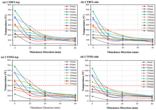
Figure 11.
Temperature curves at different depths of each cross-section under different exposure times: (a) UTBF2 top plate, (b) UTBF2 side plate, (c) UTFH3 top plate and (d) UTFH3 side plate.
The results revealed that temperatures in some locations exceeded 300 °C during the 120–210 min heating phase. Although concrete possesses high thermal inertia that induces temperature gradients across its thickness, thermal damage was predominantly concentrated near the fire-exposed surfaces, with the affected depth generally limited to within 40 mm. However, severe heating still induced surface spalling, micro-cracking, and material degradation, resulting in localized non-uniform deformation.
To further quantify the thermal impact range, the depths of thermal damage at temperature thresholds of 300 °C, 400 °C, 500 °C, and 600 °C were extracted for both top and side slabs of specimens UTBF2 and UTFH3, as summarized in Table 4 and visualized in Figure 12. Results indicate a clear trend of decreasing thermal penetration with increasing temperature. Moreover, the top slabs consistently exhibited greater thermal damage depths than the side slabs, attributable to the direct exposure to the heating plates and elevated radiation intensity.

Table 4.
Thermal damage depth of the utility tunnel structure.
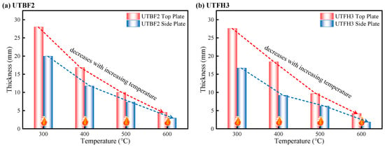
Figure 12.
Thermal damage depth at different temperatures: (a) UTBF2 and (b) UTFH3.
For instance, at the 400 °C threshold, the thermal penetration depths of the top slabs in UTBF2 and UTFH3 were 16.88 mm and 18.47 mm, respectively, whereas the corresponding values for the side slabs were 11.78 mm and 9.20 mm. The similarity of thermal response between the two specimens suggests that the type of bolt connection (stainless steel vs. high-strength steel) had a limited effect on temperature propagation, and that fire exposure itself primarily governed the development of thermal damage in the concrete.
4. Test Results and Analysis Under Post-Fire Static Loading
After the completion of fire exposure and natural cooling, post-fire static loading tests were conducted on the fire-damaged specimens UTBF2 and UTFH3. This testing phase aimed to evaluate the residual structural performance, focusing on changes in load-bearing capacity, stiffness, and failure mechanisms following thermal degradation. For reference, comparative analysis was performed against UTBC1, the control specimen that was not exposed to elevated temperatures. The following sections present detailed observations and interpretation of the failure phenomena and mechanical response under post-fire static loading conditions.
4.1. Failure Phenomena Under Post-Fire Static Loading
The post-fire static loading tests were designed to evaluate how elevated temperature exposure affected the failure behavior of prefabricated utility tunnel specimens. This section presents a comparative analysis of the observed failure modes in the unexposed reference specimen (UTBC1) and the two fire-exposed specimens (UTBF2 and UTFH3), as shown in Figure 13.
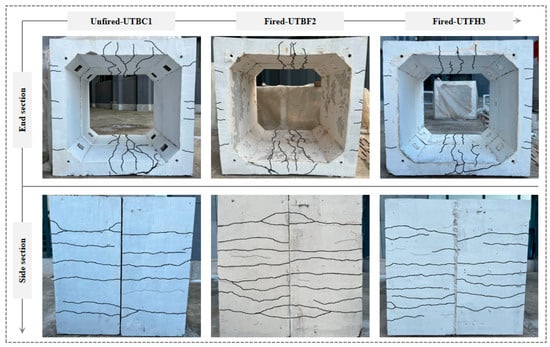
Figure 13.
The overall failure characteristics of the utility tunnel.
All specimens exhibited a flexural–shear failure pattern during loading. As the load increased, early-stage microcracks induced by high temperatures gradually propagated toward the inner regions of the wall panels. Pre-existing closed cracks reopened, and new bending-induced cracks appeared along the exterior surface of the sidewalls. The bottom slab, subjected to significant bending moments, was the first to develop vertical cracks penetrating the full thickness of the section, accompanied by audible signs of concrete crushing. These cracks later extended along the principal compressive stress paths, eventually forming diagonal shear cracks characteristic of structural failure.
A comparative analysis revealed that fire-exposed specimens (UTBF2 and UTFH3) exhibited earlier and more rapid crack propagation than the unexposed UTBC1. Particularly, UTBF2, subjected to more severe thermal degradation, experienced significant stiffness loss and widespread cracking in both the bottom slab and wall panels. In contrast, the unexposed specimen UTBC1 displayed delayed cracking, higher resistance to deformation, and improved crack control under equivalent load levels, indicating that elevated temperature substantially degraded the mechanical integrity of the utility tunnel structure.
To further investigate the failure mechanisms of the prefabricated utility tunnel structure, the crack patterns observed in the top and bottom plates at the point of structural failure were extracted for all specimens, as shown in Figure 14. Overall observations reveal significant differences in crack distribution and damage severity between unexposed and fire-exposed specimens.
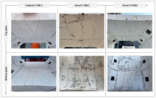
Figure 14.
The top and bottom plate crack patterns observed in the unfired and fire-damaged specimens.
In the unexposed specimen (UTBC1), cracks were sparse and fine, primarily concentrated around the mid-span region, and exhibited typical flexural characteristics. No signs of surface spalling or visible material degradation were observed, indicating that the concrete maintained its original integrity. In contrast, the fire-exposed specimens (UTBF2 and UTFH3) exhibited more extensive and severe cracking. On the top plates, vertical cracks initiated near the mid-span and extended longitudinally and laterally toward the slab edges. Localized surface discoloration and signs of mortar decomposition were evident, indicating thermal deterioration of the concrete matrix. The bottom plates also displayed more severe through-cracking, including full-depth cracks accompanied by surface spalling and coarse aggregate exposure. A comparative analysis of the bolt connection types revealed that UTBF2, which employed stainless steel bolts, developed a denser and more complex crack network, whereas UTFH3, assembled using high-strength bolts, demonstrated relatively improved crack control. This suggests that high-strength threaded bolts offer better thermal adaptability and connection stability under elevated temperature conditions.
Despite the presence of cracking and localized damage, all specimens maintained structural continuity in the haunch connection regions. The threaded bolt joints remained visually intact throughout the post-fire loading phase, with no evidence of slippage, pull-out, deformation, or separation. These observations confirm that the bolted connection system provided reliable anchorage and load transfer capacity even after fire exposure, thereby contributing to the residual structural performance of the prefabricated system.
In summary, fire exposure significantly accelerated the damage process in prefabricated utility tunnel structures, particularly in shear-critical and vulnerable zones, leading to reduced load-carrying capacity. However, the mechanical performance of key connection components remained robust, demonstrating high redundancy and fire-resistant stability.
4.2. Load–Displacement Behavior
Figure 15 presents the load–displacement curves of the three prefabricated utility tunnel specimens under static loading conditions, illustrating the impact of fire exposure and connection types on structural performance. Based on these curves, the post-fire residual load-bearing capacities and ultimate displacements of each specimen were obtained, as summarized in Table 5.
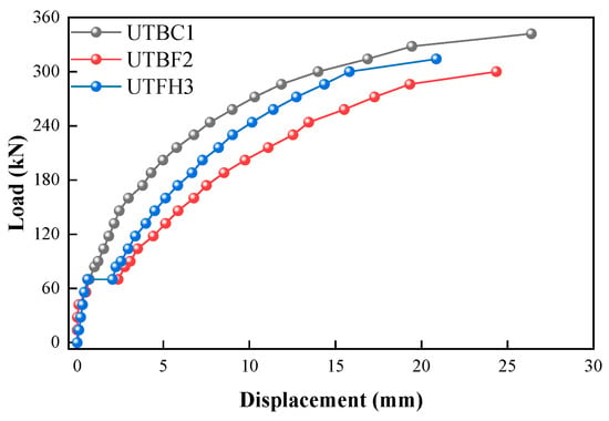
Figure 15.
The load–displacement curve of prefabricated utility tunnel.

Table 5.
The post-fire residual load-bearing capacities of the utility tunnel structure.
During the initial application of the normal service soil load, the top slabs of all specimens remained in the elastic stage, with comparable initial stiffness observed across the specimens. The unexposed specimen UTBC1 exhibited a linear increase in load with displacement up to the yield point, followed by a noticeable post-yield ascending branch. This indicates that the utility tunnel with stainless-steel threaded bolt connections maintained considerable deformation capacity and safety margin after yielding.
In contrast, both fire-exposed specimens (UTBF2 and UTFH3) showed an abrupt increase in displacement shortly after loading began, indicating that high-temperature exposure had caused significant thermal deformation and material degradation. The stiffness of both specimens was clearly reduced, as evident from the lower initial slope of the curves compared to UTBC1.
The post-fire residual load-bearing capacity of UTBF2 was reduced to 300 kN, representing a 12.28% decrease compared to UTBC1. This reduction is attributed to extensive microcracking, surface spalling, and a decline in concrete strength due to prolonged thermal exposure. UTFH3, which used high-strength threaded bolts, showed comparatively better performance, with a 4.67% higher residual capacity than UTBF2 and smaller peak displacement. This suggests improved joint stability and thermal resistance provided by high-strength bolts.
These findings confirm that high temperatures degrade both stiffness and bearing capacity in prefabricated tunnels, but the severity of degradation is strongly influenced by the mechanical and thermal properties of the bolt connections. Selecting high-strength bolts may serve as a practical mitigation strategy to enhance post-fire structural resilience.
4.3. Deformation Analysis
To evaluate the deformation characteristics of prefabricated utility tunnels under load following fire exposure, vertical and horizontal displacements were measured with respect to the pre-fire positions. Due to the structural symmetry of the specimens, only the top plate and the left plate were selected for displacement analysis. Displacement values at multiple measurement points were connected to form continuous profiles under each loading level. Figure 16 presents the vertical and lateral displacement curves of the three specimens. The horizontal axis represents the gallery section width; downward vertical displacements of the top slab are taken as positive, while outward horizontal displacements of the left plate are considered negative.
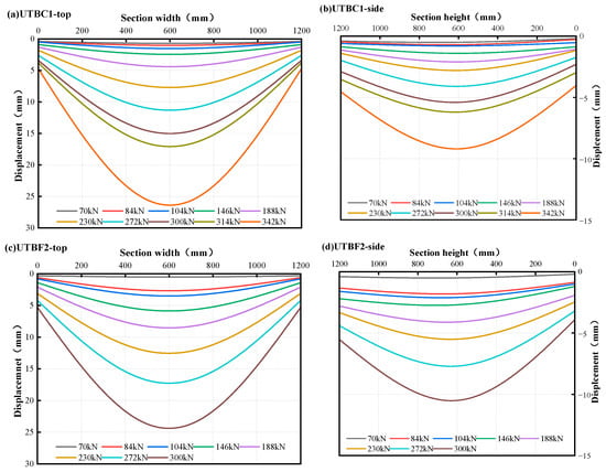
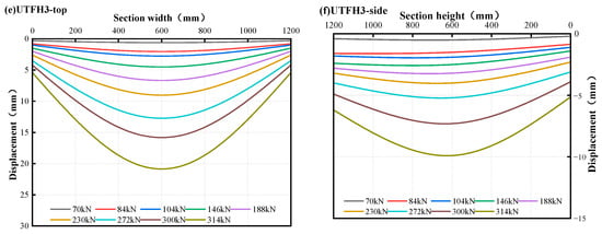
Figure 16.
Displacement variation patterns of different sections of the utility tunnel under various loads: (a) UTBC1 top slab, (b) UTBC1 side slab, (c) UTBF2 top slab, (d) UTBF2 side slab, (e) UTFH3 top slab, (f) UTFH3 side slab.
As shown in Figure 16, all specimens exhibited small overall vertical settlement under normal overburden loads, with limited mid-span deflection. As the load increased, the difference in displacement between the mid-span and haunch regions of the top plate became more pronounced, resulting in parabolic deformation profiles. For the unexposed specimen UTBC1, the top plate deflection increased almost linearly with loading, indicating stable flexural behavior. In contrast, fire-exposed specimens UTBF2 and UTFH3 exhibited nonlinear increases in vertical displacement under the same load levels. This behavior reflects material degradation caused by elevated temperatures, which reduced the structural stiffness and deformation resistance. Under identical load levels, UTBF2 and UTFH3 exhibited noticeably greater top plate deflections than UTBC1. At structural failure, the mid-span vertical displacement of the top plate in UTBF2 reached 24.36 mm, while that of UTFH3 was 20.87 mm, compared to a significantly lower value in UTBC1. These results demonstrate that the high-strength threaded bolt connections used in UTFH3 offered superior post-fire deformation restraint compared to the stainless steel bolts in UTBF2.
In terms of lateral deformation, the sidewalls experienced smaller displacements than the top slabs under the same loads. However, all specimens exhibited outward bulging of the sidewalls as loading progressed. The fire-exposed specimens showed more pronounced lateral deformation due to thermal weakening. The maximum lateral displacements of the sidewalls were recorded as 9.2 mm (UTBC1), 10.58 mm (UTBF2), and 9.94 mm (UTFH3). The relatively lower displacement in UTFH3 again highlights the better thermal stability and deformation control achieved by high-strength threaded bolt connections.
4.4. DIC Strain Field Analysis
During the tests, Digital Image Correlation (DIC) was employed to capture full-field strain distributions and track the surface deformation evolution of each utility tunnel specimen. DIC is a non-contact, image-based measurement technique that divides the speckle-patterned surface into subsets and analyzes the deformation through image correlation before and after loading. The speckle zones were applied consistently on the sidewalls of all specimens, as shown in Figure 7, enabling comparative analysis of strain evolution under different fire exposure and connection conditions.
To assess strain behavior at the point of structural failure, principal strain cloud maps generated from DIC data are presented in Figure 17. Compared to the unexposed utility tunnel specimen, the post-fire prefabricated specimens exhibited significantly denser and wider surface cracks, particularly on the inner walls, where intersecting longitudinal and transverse cracking patterns were evident. The post-fire thermal degradation led to a noticeable reduction in overall bearing capacity. After cooling, the principal strain field on the slab surface of the fire-exposed specimens exhibited abrupt gradients with multiple red and yellow strain bands, indicating regions of concentrated deformation and energy release. The slab background of Figure 17 was predominantly in blue and violet tones, consistent with the experimentally observed crack locations. Notably, the maximum surface strain in fire-damaged specimens was 35.57% higher than that of the unexposed reference specimen at failure.
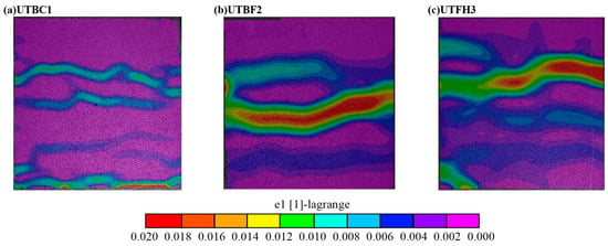
Figure 17.
Strain cloud map of the side wall panels of the utility tunnel: (a) UTBC1, (b) UTBF2 and (c) UTFH3.
Despite variations in connection configurations, both types of fire-exposed prefabricated utility tunnel specimens demonstrated similar crack evolution patterns. However, the DIC results indicate that specimens with high-strength threaded bolt connections exhibited narrower surface cracks on the sidewalls compared to those with stainless steel threaded bolts. After high-temperature exposure and natural cooling, the maximum surface strain of the high-strength bolt specimen was 10.08% lower than that of the stainless steel bolt specimen. At ultimate failure, the peak sidewall strain of the former was 39.93% lower than the latter, suggesting superior deformation control and thermal resilience in the high-strength bolt connection.
5. Finite Element Analysis of Utility Tunnel Fire Behavior
To investigate the thermo-mechanical behavior of prefabricated segmented utility tunnels under fire exposure, three-dimensional finite element models were developed using ABAQUS. The models simulate structural segments connected via stainless steel threaded bolts and high-strength threaded bolts, respectively. The simulation consists of two main phases: fire-induced thermal response and post-fire mechanical performance degradation [45]. In the thermal analysis phase, temperature-dependent thermal properties of concrete were adopted, and the standard fire curve was applied to model the non-uniform temperature distribution within the utility tunnel structure under fire conditions [46]. Subsequently, in the post-fire mechanical analysis, vertical static loads were imposed based on the previously obtained temperature fields and thermal damage zones. This approach enables the simulation of structural degradation, deformation behavior, and failure modes after fire exposure [47]. This allows for a comprehensive analysis of fire-induced effects on temperature distribution, deformation capacity, and load-bearing performance.
5.1. Establishment of the Utility Tunnel Model
The thermal field of the utility tunnel segment was simulated using the finite element software ABAQUS. Its thermal analysis module effectively models transient heat conduction and the temperature distribution within the structure. During model setup, temperature-dependent thermal properties were defined for all materials, along with the Stefan–Boltzmann constant (5.67 × 10⁻⁸ W/m2·K4) and absolute zero temperature (−273.15 °C) [48,49,50,51]. The applied fire curve matches the experimental heating protocol, with ambient temperature set to 20 °C. Fire exposure was introduced through both thermal convection and radiation, where the convection coefficients were set to 25 W/(m2·°C) for the fire-exposed surface and 9 W/(m2·°C) for the unexposed surface. The radiation coefficient was set to 0.85 [52]. The overall numerical model of the utility tunnel is shown in Figure 18. In accordance with the experimental setup, the thermal loads were applied to the inner surfaces of the tunnel segment, replicating the fire exposure boundaries in the physical tests.
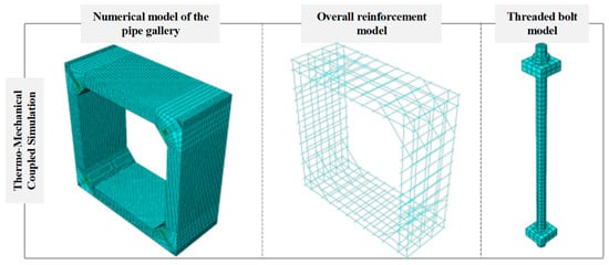
Figure 18.
Overall numerical model of utility tunnel.
While the current model adopts standard values for thermal boundary conditions based on BS EN 1991-1-2 [52], it is acknowledged that variations in key parameters—such as convection coefficients and bolt preload—may affect simulation accuracy. A dedicated parametric study will be conducted in future work to quantify these effects.
A sequential thermo-mechanical coupling approach was employed. First, thermal conduction analysis was performed. The resulting temperature field was then imported as a predefined field into the structural model for subsequent mechanical analysis [53]. To ensure compatibility, the structural model shared the same mesh and node numbering as the thermal model. Thermal elements were replaced with structural elements. In the utility tunnel model, the concrete was meshed using a solid element (DC3D8 for heat transfer analysis and C3D8 for structural analysis) and the steel was meshed using a link element [54]. Tie constraints were applied between the reinforcement and concrete, and between bolt washers and concrete, with no relative slip considered. Hard contact was used in the normal direction between utility tunnel segments, allowing separation with zero tensile force, while tangential contact was modeled using a penalty friction formulation with a friction coefficient of 0.3 [55,56,57].
Three analysis steps were defined based on the experimental procedure: Step 1—bolt preload was applied using the Bolt Load feature and locked after the step; Step 2—a line load was applied to the top slab to simulate earth cover loading and maintained throughout the next step; Step 3—the predefined temperature field was applied to perform the structural analysis under coupled thermal–mechanical conditions.
Each of the three simulation steps employed specific material constitutive models to accurately reflect the thermal and mechanical behavior of concrete and steel under different conditions. The material definitions are introduced as follows:
- (1)
- Thermal Properties at Elevated Temperatures
The temperature-dependent thermal properties of concrete, including thermal conductivity and specific heat capacity , were defined using piecewise empirical expressions as recommended in [52], based on the temperature range:
where is the thermal conductivity of concrete (W/(m·°C)); is the specific heat capacity of concrete (J/(kg·°C)); T is the temperature (°C).
For steel, the thermal properties at elevated temperatures were defined according to the GB 51249-2017 [58], with the calculation formula as follows:
where is the thermal conductivity of steel (W/(m·°C)); is the specific heat capacity of steel (J/(kg·°C)); T is the temperature (°C).
- (2)
- Mechanical Properties at Elevated Temperatures
The mechanical behavior of concrete was modeled using the Concrete Damaged Plasticity (CDP) model initially proposed by Lubliner et al. [59] and later modified by Lee et al. [60]. This constitutive framework assumes that the dominant failure mechanisms in concrete are tensile cracking and compressive crushing, and it has been widely adopted in numerical simulations of concrete structures under various loading conditions. The behavior of reinforcing steel was defined using a bilinear elastoplastic model [61], in which the strain hardening modulus was assumed to be 1% of the initial elastic modulus [62].
In addition, both concrete and steel exhibit noticeable thermal degradation in mechanical properties when subjected to elevated temperatures. In the present finite analysis, the temperature-induced softening of both elastic modulus and strength was taken into account for concrete and reinforcing steel. According to the European standard BS EN 1992-1-2 [52], the normalized reduction factors of compressive strength (fc), yield strength (fs) and elastic modulus (Ec and Es) as functions of temperature were adopted. The variation in these parameters with temperature is illustrated in Figure 19. These temperature-sensitive material models were embedded into the sequential thermo-mechanical simulation framework to replicate structural behavior under elevated temperatures.
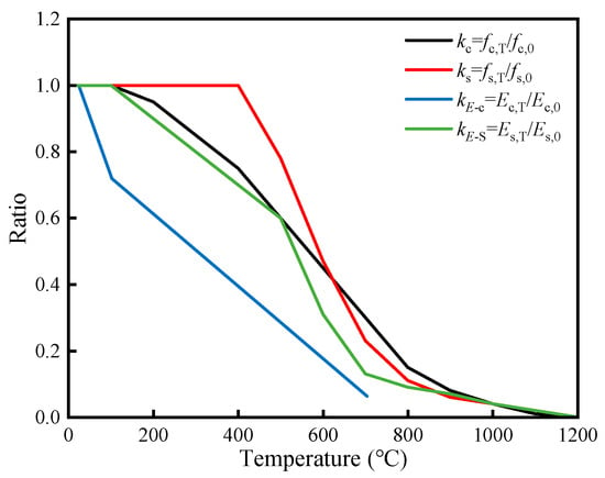
Figure 19.
Degradation of material mechanical properties at elevated temperatures.
To better simulate the mechanical and thermal behavior of the utility tunnel structure while improving computational efficiency, a mesh sensitivity analysis was first conducted. Based on the analysis results, the element size was set to 20 mm for both concrete and reinforcement, while an average mesh size of 30 mm was adopted for the remaining components. For simplicity, and consistent with previous studies [63], the bond–slip interaction between reinforcement and concrete was not considered in the present model. Instead, a perfect bond was assumed between the two materials.
5.2. Thermo-Mechanical Coupling Simulation Results
To visually represent the temperature distribution within the utility tunnel segment under fire conditions, temperature distribution contours and thermal stress contours of specimen UTFH3 were extracted at 60 and 120 min of heating, as shown in Figure 20.
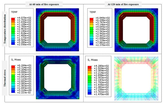
Figure 20.
Temperature distribution contours and thermal stress contours of specimen UTFH3.
The simulated temperature contours indicate that the internal temperature of the utility tunnel segment increases progressively with prolonged fire exposure. At any given moment, the temperature inside the cross-section is significantly higher than that on the external surfaces. As concrete is a thermally inert material with high heat capacity and low thermal conductivity, the rate of heat transfer within it is relatively slow. Consequently, the longer the heating duration, the greater the temperature gradient between the interior and exterior. This pronounced temperature differential induces thermal stress within the utility tunnel. The non-uniform temperature distribution leads to uneven thermal expansion, which generates additional stress in the concrete and ultimately causes damage to the structure.
A further comparison between the finite element simulation results and experimental measurements was conducted for specimen UTFH3. Two thermocouples, T3 and T6, located at the mid-height measurement surface, were selected for validation. The experimental and numerical temperature–time curves are plotted in Figure 21.
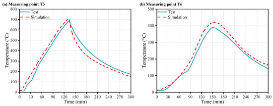
Figure 21.
Comparison of experimental and simulated temperature–time curves: (a) Measuring point T3, (b) Measuring point T6.
As shown in the curves, the simulated temperatures are slightly higher than the experimental results, yet the overall trends at both measurement points exhibit strong agreement, indicating a good match between the numerical and physical thermal fields. At measuring point T3, the simulated curve shows an earlier temperature rise in the initial heating phase compared to the experimental curve. This discrepancy is primarily due to the delayed heating response in the physical test setup, which is influenced by the furnace conditions and environmental factors, but has a limited impact on the final temperature values. For point T6, a distinct temperature plateau around 100 °C is observed in the experimental curve, which does not appear in the simulation. This phenomenon is attributed to the evaporation of free water and the endothermic effect of water vaporization within the concrete during fire exposure. The large amount of heat absorbed during this phase leads to a temporary stagnation in the temperature rise. In contrast, the finite element model assumes isotropic and homogeneous material properties and does not account for moisture content or phase change effects in concrete, which explains the absence of the temperature plateau in the simulation results.
Although some discrepancies exist between the simulated and measured values, the overall consistency in trend and thermal behavior confirms the validity and applicability of the adopted finite element thermal analysis method. The simulation results provide a reliable basis for subsequent structural performance analysis under fire conditions.
5.3. Post-Fire Simulation Results
In the post-fire stage, the structural behavior of the prefabricated utility tunnel segments was evaluated using thermal–mechanical sequential analysis. The mechanical properties of concrete and reinforcement were adjusted based on the peak temperature history obtained from the preceding thermal field simulation [64,65]. This modeling approach reflects the fact that post-fire structural response is predominantly governed by residual material properties, which depend on the maximum temperatures experienced during fire exposure [66,67].
The post-fire constitutive models were implemented by applying temperature-dependent degradation to the mechanical parameters. Specifically, the peak temperature at each node, as calculated from the thermal simulation, was imported into the structural model to define the corresponding residual properties. For concrete, the post-fire material model proposed by Song et al. [68] was adopted. Detailed material properties of steel corresponding to the post-fire loading phase could be found in Li et al. [69]. This approach allowed for the reliable evaluation of the residual load-bearing capacity of the prefabricated utility tunnel segments connected with threaded bolts after fire exposure.
Based on the above simulation method, the stress and damage contours of specimen UTFH3 after fire exposure were extracted for analysis, as shown in Figure 22. The simulation results for UTFH3, compared with the experimental observations, indicate that damage at the haunch corners and diagonal cracks on the top and bottom slabs was primarily caused by compressive stresses. Tensile cracks were concentrated on the inner faces of the top and bottom slabs and the outer surfaces of the sidewalls. The distribution of reinforcement stress closely matched the tensile damage zones in the concrete. Due to the inherent nonhomogeneous and anisotropic nature of concrete, the actual failure observed in the experiment showed more pronounced diagonal cracking in the bottom slab only, differing slightly from the symmetric crack patterns predicted in the simulation.
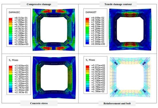
Figure 22.
The stress and damage contours of specimen UTFH3 after fire exposure.
The simulated and experimental load–displacement curves are compared in Figure 23. Both sets of results show similar trends. The experimental ultimate bending capacity and maximum displacement were slightly lower than those from the simulation.
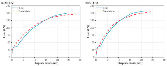
Figure 23.
The simulated and experimental load–displacement curves: (a) UTBF2, (b) UTFH3.
As observed in the load–displacement curves, both simulation and experimental results showed that the top slab of the utility tunnel remained in the elastic stage under service load levels. The initial response curves coincided well. After exposure to fire, slight deviations appeared, likely due to the uneven heating and discontinuous load application during the experiment, causing sudden displacement jumps in the test that were not present in the idealized simulation. Nevertheless, both approaches captured the stiffness degradation caused by fire. When the applied load approached 250 kN, the experimental and numerical curves again showed good agreement with only minor divergence, attributed to idealizations in the material constitutive models used in the simulation. These discrepancies were small and acceptable for engineering purposes.
To quantitatively evaluate the accuracy of the numerical model, a detailed comparison between simulated and experimental results was conducted for key performance indicators, including top slab temperature, limit displacement, and residual load-bearing capacity. The results are summarized in Table 6.

Table 6.
Comparison between experimental and numerical results.
For specimen UTBF2, the simulated peak top slab temperature (T3) was 731.2 °C, close to the experimental 722.9 °C (error: 1.15%). At internal point T6, the deviation was 7.13%. The simulated limit displacement and residual load capacity were 26.61 mm and 291.91 kN, with errors of 9.24% and −2.70%, respectively. For specimen UTFH3, the top slab and internal temperatures had errors of 3.77% and 8.18%, respectively. The limit displacement error was 9.68%, and the residual capacity deviation was −2.49%.
Overall, all simulation results fall within a relative error range of ±10%, which is generally considered acceptable in structural fire engineering. These outcomes verify the predictive reliability and robustness of the finite element model, particularly in estimating the post-fire residual capacity of prefabricated utility tunnel segments with different bolt types.
Specifically, the peak load discrepancy was 8.09 kN and 7.81 kN for UTBF2 and UTFH3, corresponding to relative errors of 2.70% and 2.49%, respectively. These differences fall within acceptable engineering margins and confirm the validity of the finite element model for simulating the fire-damaged performance of longitudinally bolted prefabricated utility tunnel segments.
In conclusion, the proposed finite element model can reliably predict the post-fire residual load-bearing capacity of the prefabricated utility tunnel segments with longitudinal threaded bolt connections.
6. Conclusions
In the present study, a comprehensive experimental and numerical investigation was conducted on prefabricated utility tunnel segments subjected to fire exposure, focusing on the thermo-mechanical degradation and post-fire structural performance. Three utility tunnel specimens with different bolt connection types (stainless steel and high-strength threaded bolts) were tested under simulated fire and static loading conditions. The main conclusions are summarized as follows:
- (1)
- Under fire exposure, the internal temperature field of the utility tunnel exhibited a distinctly nonlinear distribution. A temperature plateau near 100 °C emerged due to moisture evaporation, influenced by fire depth and heating proximity. The maximum internal–external temperature difference reached 536.8 °C, leading to significant thermal gradients and surface microcracking.
- (2)
- Structural failure of the utility tunnel specimens was dominated by 45° bending-shear cracks in the bottom slab, with multiple cracks nearly penetrating the entire thickness at the mid-span. Despite structural damage, no significant opening was observed at the bolt connections, indicating that the threaded bolt joints maintained stable mechanical performance even after fire exposure.
- (3)
- Post-fire specimens exhibited extensive cracking, stiffness loss, and reduced ductility. The maximum surface strain increased by 35.57%, and load-bearing capacity dropped by 12.28% compared to unexposed specimens. Nevertheless, all retained sufficient residual strength exceeding design requirements, confirming structural integrity after fire.
- (4)
- Bolt connection type significantly influenced post-fire performance. Specimens with high-strength threaded bolts showed 13.87% less residual deformation, 10.08% lower peak surface strain, and 4.67% higher residual load capacity than those with stainless steel bolts, indicating better thermal resistance and structural stability.
- (5)
- The validated finite element model accurately reproduced the temperature field and load–displacement behavior. The ratio between simulated and experimental residual bearing capacity was 0.943, validating the reliability of the finite element model. It provides a reliable tool for investigating fire-induced damage and supports performance-based design of utility tunnels with threaded connections.
- Engineering Implications:
These results suggest that high-strength bolts outperform stainless steel bolts in maintaining post-fire mechanical performance, particularly in terms of residual strength and deformation control. This provides engineering support for selecting bolt materials in prefabricated utility tunnel designs, especially in fire-prone or critical zones. The findings also indicate the necessity of integrating connection details into fire resistance assessments. Future fire design codes may benefit from specifying thermal stability criteria for joint materials and incorporating residual capacity checks after fire exposure.
- Limitations and Future Work:
This study provides foundational insights into the fire performance of prefabricated utility tunnels; however, some limitations should be acknowledged. The use of one specimen per condition and idealized boundary conditions may limit the statistical robustness and direct field applicability of the findings. While the 1:3 scaled model enables controlled investigation, certain thermal properties—such as heat conduction and thermal inertia-may not fully replicate full-scale behavior. The numerical simulations were based on simplified assumptions, including perfect bond conditions and the exclusion of complex thermal effects such as moisture migration, spalling, and soil-structure heat exchange. Additionally, internal utility loads and lateral soil pressure were not considered in the current setup. These simplifications were necessary to maintain feasibility but also highlight key directions for future work, which will include increased specimen numbers, more representative fire scenarios, and enhanced modeling of multi-directional loading and soil–structure interaction to further improve practical relevance.
Author Contributions
Conceptualization, B.Z.; methodology, B.Z.; software, H.L.; validation, H.L. and Z.L.; formal analysis, H.L.; investigation, B.Z.; resources, B.Z.; data curation, H.L.; writing—original draft preparation, H.L.; writing—review and editing, B.Z.; visualization, Q.Y.; supervision, B.Z.; project administration, B.Z. All authors have read and agreed to the published version of the manuscript.
Funding
This research was funded by the Science and Technology Development Program of Jilin Province, China (grant number: 20200403071SF).
Data Availability Statement
All data generated or analysed during this study are included in this article. All data included in this study are available upon request by contact with the corresponding author.
Conflicts of Interest
The authors declare no conflicts of interest.
Abbreviations
The following abbreviations are used in this manuscript:
| DIC | Digital image correlation |
| CDP | Concrete Damaged Plasticity |
References
- Wang, Z.; Wang, Y.; Huang, W.; Shan, H.; Zhu, L. Research on natural foundation bearing capacity and foundation pit settlement of prefabricated utility tunnel. Adv. Civ. Eng. 2022, 1, 5361199. [Google Scholar] [CrossRef]
- Wang, Y.; Zhang, Y.; Huang, Z.; Wang, K.; Tang, A. Seismic response characteristics of a utility tunnel crossing a river considering hydrodynamic pressure effects. Buildings 2024, 14, 3434. [Google Scholar] [CrossRef]
- Cano-Hurtado, J.J.; Canto-Perello, J. Sustainable development of urban underground space for utilities. Tunn. Undergr. Space Technol. 1999, 14, 335–340. [Google Scholar] [CrossRef]
- Wang, X.; Yao, Z.; Wang, Y.; Yang, Y.; Zhang, H. Modelling the smoke flow characteristics of a comprehensive pipe gallery fire with rectangular section. Buildings 2024, 14, 1937. [Google Scholar] [CrossRef]
- Gao, Z.H.; Ji, J.; Wan, H.X.; Li, L. Experimental investigation on transverse ceiling flame length and temperature distribution of sidewall confined tunnel fire. Fire Saf. J. 2017, 91, 371–379. [Google Scholar] [CrossRef]
- Lei, P.; Chen, C.; Zhang, Y.; Liu, J. Experimental study on temperature profile in a branched tunnel fire under natural ventilation considering different fire locations. Int. J. Therm. Sci. 2021, 159, 106631. [Google Scholar] [CrossRef]
- Wang, F.; Wang, M.; Carvel, R.; Wang, Y. Numerical study on fire smoke movement and control in curved road tunnels. Tunn. Undergr. Space Technol. 2017, 67, 1–7. [Google Scholar] [CrossRef]
- Zhao, Y.C.; Zhu, G.Q.; Gao, Y.J.; Tao, H.J. Study on temperature field of fire smoke in utility tunnel with different cross sections. Procedia Eng. 2018, 211, 1043–1051. [Google Scholar] [CrossRef]
- Ji, J.; Fu, Y.Y.; Fan, C.G.; Gao, Z.H.; Li, K.Y. An experimental investigation on thermal characteristics of sidewall fires in corridor-like structures with varying width. Int. J. Heat. Mass. Tran. 2015, 84, 562–570. [Google Scholar] [CrossRef]
- Çelik, Z.; Urtekin, Y. Effects of High Temperature and Water Re-Curing on the Flexural Behavior and Mechanical Properties of Steel–Basalt Hybrid Fiber-Reinforced Concrete. Appl. Sci. 2025, 15, 1587. [Google Scholar] [CrossRef]
- Qian, Y.; Yang, D.; Xia, Y.; Gao, H.; Ma, Z. Properties and improvement of ultra-high performance concrete with coarse aggregates and polypropylene fibers after high-temperature damage. Constr. Build. Mater. 2023, 364, 129925. [Google Scholar] [CrossRef]
- Wang, S.; Zhou, S.; Yang, K.; Zhang, G. Study on Residual Load-Bearing Capacity of Composite Steel Truss Bridge Girders After Vehicle Fire. Buildings 2025, 15, 2820. [Google Scholar] [CrossRef]
- Wang, Y.; Liu, Z.; Qu, S.; Gong, J.; Lyu, X. Fire resistance of reinforced concrete beams: State of the art, analysis and prediction. Constr. Build. Mater. 2023, 409, 134029. [Google Scholar] [CrossRef]
- Ji, J.; Bi, Y.; Venkatasubbaiah, K.; Li, K. Influence of aspect ratio of tunnel on smoke temperature distribution under ceiling in near field of fire source. Appl. Therm. Eng. 2016, 106, 1094–1102. [Google Scholar] [CrossRef]
- Zhou, X.; Zhu, G.; Liu, H.; Liang, Z. Experimental investigation on the influence of linear fire source along the wall on the temperature distribution in tunnel. Case Stud. Therm. Eng. 2019, 14, 100473. [Google Scholar] [CrossRef]
- Xu, G.; Zhu, G.; Pan, R.; Liu, X. Experimental study on combustion parameters and temperature distribution of linear fire under different oxygen concentration in tunnel. Results Eng. 2021, 11, 100272. [Google Scholar] [CrossRef]
- Cao, B.; Liu, H.; Fan, R.; Ju, X.; Yang, L. Experimental and theoretical investigation of longitudinal temperature attenuation and smoke movement in urban utility tunnel fires. Fire 2024, 7, 123. [Google Scholar] [CrossRef]
- Vauquelin, O.; Mégret, O. Smoke extraction experiments in case of fire in a tunnel. Fire Saf. J. 2002, 37, 525–533. [Google Scholar] [CrossRef]
- Liu, H.; Zhu, G.; Pan, R.; Yu, M.; Liang, Z. Experimental investigation of fire temperature distribution and ceiling temperature prediction in closed utility tunnel. Case Stud. Therm. Eng. 2019, 14, 100493. [Google Scholar] [CrossRef]
- Ingason, H.; Lönnermark, A. Heat release rates from heavy goods vehicle trailer fires in tunnels. Fire Saf. J. 2005, 40, 646–668. [Google Scholar] [CrossRef]
- Lin, J.; Dong, Y.; Duan, J.; Zhang, D.; Zheng, W. Experiment on single-tunnel fire in concrete immersed tunnels. Tunn. Undergr. Space Technol. 2021, 116, 104059. [Google Scholar] [CrossRef]
- Feist, C.; Aschaber, M.; Hofstetter, G. Numerical simulation of the load-carrying behavior of RC tunnel structures exposed to fire. Finite Elem. Anal. Des. 2009, 45, 958–965. [Google Scholar] [CrossRef]
- Yan, Z.; Liu, K.; Shen, Y. Numerical study on mechanical properties of large diameter double-layer shield tunnels under the elevated temperatures in fire. IOP Conf. Ser. Earth Environ. 2021, 861, 072045. [Google Scholar] [CrossRef]
- Shen, Y.; Ling, J.; Wang, W.; Zhu, H.; Yan, Z. 3D numerical investigation on response of shield tunnel under combined effects of fire and structural loading. Tunn. Undergr. Space Technol. 2022, 128, 104659. [Google Scholar] [CrossRef]
- Yang, Y.; Wang, C.; Yuan, X. Temperature and structural properties of prefabricated pipe gallery during whole fire process. Struct. Eng. Mech. 2025, 94, 269–284. [Google Scholar] [CrossRef]
- Zhou, X.; Zeng, B.; Sun, X.; Jiao, Y.Y.; Hu, J. A novel steel bulkhead based on the method of prefabrication and assembly and its first application to the Yuliangzhou immersed tunnel. Tunn. Undergr. Space Technol. 2023, 133, 104951. [Google Scholar] [CrossRef]
- Thulasirangan, M.; Reddy, K.K.; Al-Ameri, R.; Kafle, B. A Review on Design Considerations and Connection Techniques in Modular Composite Construction. Appl. Sci. 2025, 15, 5256. [Google Scholar] [CrossRef]
- Lin, Z.; Guo, C.; Ni, P.; Cao, D.; Huang, L.; Guo, Z.; Dong, P. Experimental and numerical investigations into leakage behaviour of a novel prefabricated utility tunnel. Tunn. Undergr. Space Technol. 2020, 104, 103520. [Google Scholar] [CrossRef]
- Pan, Y.; Yi, D.; Wu, W.; Bao, Y.; Guo, R. Mechanical performance test and finite element analysis of prefabricated utility tunnel L-shaped joint. Struct. Des. Tall Spec. Build. 2020, 29, 1752. [Google Scholar] [CrossRef]
- Xue, W.; Chen, S.; Wang, Q. Pseudo-static tests on double-cell precast utility tunnel composed of groove-shaped elements with prestressing tendons. Structures 2025, 71, 107912. [Google Scholar] [CrossRef]
- Ding, W.; Gong, Y.; Qiao, Y.; Gong, C. Experimental investigation on mechanical behavior of segmental joint under combined loading of compression-bending-shear. Tunn. Undergr. Space Technol. 2020, 98, 103346. [Google Scholar] [CrossRef]
- Liu, X.; Liu, Z.; Ye, Y.; Bai, Y.; Zhu, Y. Mechanical behavior of quasi-rectangular segmental tunnel linings: Further insights from full-scale ring tests. Tunn. Undergr. Space Technol. 2018, 79, 304–318. [Google Scholar] [CrossRef]
- Zhang, J.; Zhang, Y.; Peng, C.; Lei, Y.; Zhang, A.; Zuo, Z.; Chen, Z. Experimental and numerical investigation into full-scale model of new type assembled integral utility tunnel. Buildings 2023, 13, 1428. [Google Scholar] [CrossRef]
- ISO834-1; Fire-Resistance Tests—Elements of Building Construction—Part 1: General Requirements. International Organization for Standardization: Geneve, Switzerland, 2025.
- NFPA92: 2021; Standard for Smoke Control System. National Fire Protection Association: Quincy, MA, USA, 2021.
- Xu, D.; Li, Y.; Li, J.; Zhong, H.; Li, J.; Tu, D.; Huang, Y. Evaluating the combustion and flame extension characteristics of cable fire in utility tunnels with spontaneous combustion scenarios: An experimental study. Tunn. Undergr. Space Technol. 2023, 140, 105244. [Google Scholar] [CrossRef]
- Xu, Q.; Bai, C.; Peng, J.; Lu, Q.; Zhao, J. Model test of prefabricated underground utility tunnel crossing active ground fissures. Tunn. Undergr. Space Technol. 2023, 140, 105279. [Google Scholar] [CrossRef]
- Xu, D.; Li, Y.; Yang, X.; Zhong, H.; Li, J.; Li, J.; Huang, Y. Enhancing resilience in urban utility tunnels power transmission systems: Analysing temperature distribution in near-wall cable fires for risk mitigation. Tunn. Undergr. Space Technol. 2024, 152, 105911. [Google Scholar] [CrossRef]
- Liang, J.; Zhang, J.; Dong, B.; Xu, A.; Ba, Z. Shaking table tests on the seismic performance of prefabricated T-shaped cross utility tunnel. Structures 2023, 58, 105516. [Google Scholar] [CrossRef]
- Liang, Z.H.; Zhu, G.Q.; Liu, H.N.; Zhou, X. Flame characteristic and ceiling temperature distribution under the effect of curved sidewall. Case Stud. Therm. Eng. 2019, 14, 100453. [Google Scholar] [CrossRef]
- Di, Q.; PengKun, G.; Fahid, A.; Raza, M.; Safiuddin, M. A comprehensive review on fire damage assessment of reinforced concrete structures. Case Stud. Constr. Mater. 2022, 16, 00843. [Google Scholar] [CrossRef]
- Nan, H.; Kheyroddin, N.E.; Torres, A.; Guo, Y.; Zhou, X. Experimental study of fire damage to reinforced concrete tunnel slabs. Fire Saf. J. 2022, 127, 103504. [Google Scholar] [CrossRef]
- Shuna, N.; Gernay, T. A framework for probabilistic fire loss estimation in concrete building structures. Struct. Saf. 2021, 88, 102029. [Google Scholar] [CrossRef]
- Wróblewska, J.; Kowalski, R. Assessing concrete strength in fire-damaged structures. Constr. Build. Mater. 2020, 254, 119122. [Google Scholar] [CrossRef]
- Husem, M. The effect of high temperature on compressive and flexural strengths of ordinary and high-performance concrete. Fire Saf. J. 2006, 41, 155–163. [Google Scholar] [CrossRef]
- Jin, L.; Li, X.; Zhang, R.; Zhao, Z.; Tang, Y. Bond-slip behavior between concrete and deformed rebar at elevated temperature: Mesoscale simulation and formulation. Int. J. Mech. Sci. 2021, 205, 106622. [Google Scholar] [CrossRef]
- Jin, L.; Li, X.; Zhang, R.; Zhao, Z.; Tang, Y. Modelling of bond behavior of deformed bar embedded in concrete after heating to high temperatures: A mesoscale study. Constr. Build. Mater. 2022, 334, 127456. [Google Scholar] [CrossRef]
- Kodur, V.K.R.; Wang, T.C.; Cheng, F.P. Predicting the fire resistance behaviour of high strength concrete columns. Cem. Concr. Compos. 2004, 26, 141–153. [Google Scholar] [CrossRef]
- Capua, D.D.; Mari, A.R. Nonlinear analysis of reinforced concrete cross-sections exposed to fire. Fire Saf. J. 2007, 42, 139–149. [Google Scholar] [CrossRef]
- Dwaikat, M.B.; Kodur, V.K.R. A numerical approach for modeling the fire induced restraint effects in reinforced concrete beams. Fire Saf. J. 2008, 43, 291–307. [Google Scholar] [CrossRef]
- Rong, Q.; Peng, C.; Hou, X.; Chang, Y.; Fan, T. Finite Element Modeling of Dynamic Response of RPC Columns and Frames Under Coupled Fire and Explosion. Appl. Sci. 2025, 15, 1668. [Google Scholar] [CrossRef]
- BS EN 1992-1-2: 2023; Design of Concrete Structures-Part 1-2: General Rules-Structural Fire Design. European Committee for Standardization: Brussels, Belgium, 2023.
- Kodur, V.; Dwaikat, M.; Raut, N. Macroscopic FE model for tracing the fire response of reinforced concrete structures. Eng. Struct. 2009, 31, 2368–2379. [Google Scholar] [CrossRef]
- Zhou, H.; Li, S.; Chen, L.; Zhang, C. Fire tests on composite steel-concrete beams prestressed with external tendons. J. Constr. Steel Res. 2018, 143, 62–71. [Google Scholar] [CrossRef]
- Zhao, W.; Zhu, B. Theoretical model for the bond–slip relationship between ribbed steel bars and confined concrete. Struct. Concr. 2018, 19, 548–558. [Google Scholar] [CrossRef]
- Jin, L.; Liu, M.; Zhang, R.; Du, X. 3D meso-scale modelling of the interface behavior between ribbed steel bar and concrete. Eng. Fract. Mech. 2020, 239, 107291. [Google Scholar] [CrossRef]
- Chiriatti, L.; Mercado-Mendoza, H.; Apedo, K.L.; Fond, C.; Feugeas, F. A study of bond between steel rebar and concrete under a friction-based approach. Cem. Concr. Res. 2019, 120, 132–141. [Google Scholar] [CrossRef]
- GB 51249-2017; Code for Fire Safety of Steel Structures in Buildings. China Planning Press: Beijing, China, 2017.
- Lubliner, J.; Ollivier, J.; Oller, S.; Onate, E. A plastic-damage model for concrete. Int. J. Solids Struct. 1989, 25, 299–326. [Google Scholar] [CrossRef]
- Lee, J.; Fenves, G. Plastic-damage model for cyclic loading of concrete structures. J. Eng. Mech. 1998, 124, 892–900. [Google Scholar] [CrossRef]
- Xiao, S. Numerical study of dynamic behaviour of RC beams under cyclic loading with different loading rates. Mag. Concrete. Res. 2015, 67, 325–334. [Google Scholar] [CrossRef]
- Jin, L.; Zhang, R.; Dou, G.; Xu, J.; Du, X. Experimental and numerical study of reinforced concrete beams with steel fibers subjected to impact loading. Int. J. Damage Mech. 2018, 27, 1058–1083. [Google Scholar] [CrossRef]
- Liao, W.; Li, M.; Zhang, W.; Tian, Z. Experimental studies and numerical simulation of behavior of RC beams retrofitted with HSSWM-HPM under impact loading. Eng. Struct. 2017, 149, 131–146. [Google Scholar] [CrossRef]
- Jin, L.; Lan, D.Q.; Zhang, R.B.; Li, J.; Qian, K. Performance of RC beam-column assemblies during and after elevated temperature to resist progressive collapse. Eng. Struct. 2023, 283, 115802. [Google Scholar] [CrossRef]
- Espinos, A.; Gardner, L.; Romero, M.L.; Hospitaler, A. Fire behaviour of concrete filled elliptical steel columns. Thin-Walled Struct. 2011, 49, 239–255. [Google Scholar] [CrossRef]
- Gernay, T.; Franssen, J. A plastic-damage model for concrete in fire: Applications in structural fire engineering. Fire Saf. J. 2015, 71, 268–278. [Google Scholar] [CrossRef]
- Bamonte, P.; Lo Monte, F. Reinforced concrete columns exposed to standard fire: Comparison among different constitutive models for concrete at high temperature. Fire Saf. J. 2015, 71, 310–323. [Google Scholar] [CrossRef]
- Song, T.Y.; Han, L.H.; Uy, B. Performance of CFST column to steel beam joints subjected to simulated fire including the cooling phase. J. Constr. Steel Res. 2010, 66, 591–604. [Google Scholar] [CrossRef]
- Li, S.; Han, L.H.; Wang, F.C.; Hou, C.C. Seismic behavior of fire-exposed concrete-filled steel tubular (CFST) columns. Eng. Struct. 2020, 224, 111085. [Google Scholar] [CrossRef]
Disclaimer/Publisher’s Note: The statements, opinions and data contained in all publications are solely those of the individual author(s) and contributor(s) and not of MDPI and/or the editor(s). MDPI and/or the editor(s) disclaim responsibility for any injury to people or property resulting from any ideas, methods, instructions or products referred to in the content. |
© 2025 by the authors. Licensee MDPI, Basel, Switzerland. This article is an open access article distributed under the terms and conditions of the Creative Commons Attribution (CC BY) license (https://creativecommons.org/licenses/by/4.0/).