Abstract
Steel energy dissipation devices are integral to seismic design, as they help reduce structural deformations during strong earthquakes by absorbing and dissipating energy through large inelastic deformations. This research provides new insights into the cyclic behavior and constitutive modeling of carbon steel SS275, a domestically manufactured material in Korea specifically used for seismic energy dissipation applications. To characterize its mechanical response, monotonic and strain-controlled cyclic loading tests are conducted on nine machined coupons. The cyclic tests are performed under constant strain amplitudes ranging from ±0.5% to ±3.0%. Experimental strain–life data obtained at these amplitudes are used to determine the Coffin–Manson parameters, while the cyclic stress–strain relationship is defined using the Ramberg–Osgood equation. Furthermore, material parameters for the Chaboche nonlinear hardening model are extracted from the experimental results and validated through finite element simulations of coupon tests in ABAQUS, ensuring close agreement with the measured cyclic response. Following the coupon-level analysis, a member-scale test is performed on a buckling-restrained brace (BRB) fabricated from SS275 steel. The calibrated Chaboche parameters are then applied in numerical simulations of the BRB, and the results are compared with experimental data to assess the model’s predictive capability for seismic performance.
1. Introduction
Recent advancements in lateral-load resisting systems for structures have focused on the incorporation of energy dissipation devices, effectively minimizing deformations from strong winds and earthquakes [,,]. Under severe seismic situations, these structural devices experience small numbers of large inelastic strain cycles, which are identified as low-cycle fatigue. The responses of structures to these loading conditions depends on the member geometry and hysteretic behavior of the employed materials, which is investigated through fatigue experiments under large strain amplitudes [,]. Mild carbon steel, also known simply as “mild steel,” is a type of low-carbon steel that contains a relatively low percentage of carbon compared to other types of steel and is commonly used in structural applications across the world because of its advantageous characteristics like better ductility, specific low yield stress, soft nature, easy machineability, and weldability [].
In the past, a large amount of research has been conducted on mild carbon steel to analyze its hysteretic behavior because of an intensified emphasis on specifying design standards for steel structural members under low-cycle-fatigue (LCF) loadings after the Northridge Earthquake in 1994 and Kobe earthquake in 1995 [,]. Dusicka et al. [] conducted experiments to investigate the hysteretic response and uniaxial fatigue life of five types of steel plates used in United States under axial strain amplitudes from ±1% to ±7% and found that the fatigue life of all the steel plates was generally consistent, with strain rate having no significant impact on their hysteresis behavior. Nip et al. [] examined the extremely low-cycle fatigue properties of three European steel grades: hot-rolled carbon steel, cold-formed carbon steel, and cold-formed austenitic stainless steel. The findings revealed that, while all materials had comparable fatigue life, their fracture ductility differed. Dehghani et al. [] investigated the properties of Canadian grade 350WT category 4 steel under various loading conditions, including uniaxial tensile, constant-amplitude, and variable-amplitude cyclic loading, at both room and subfreezing temperatures. The results indicated that the material exhibited similar ductility at both temperatures, with no significant reduction in low-cycle fatigue life at subfreezing temperatures. Annan and Beaumont [] evaluated the low-cycle performance of Canadian carbon steel grade 350WT and austenitic stainless-steel grade 304L under large cyclic strains. Their findings showed that stainless steel had superior ductility and greater strain-hardening capacity, but a shorter fatigue life compared to carbon steel. For Chinese grade Q235 steel, Refs. [,,] conducted extensive low-cycle fatigue experiments to study its cyclic performance and proposed constitutive models to better simulate the material’s behavior in steel structures under cyclic loads. Narendra et al. [] conducted Low-Cycle Fatigue (LCF) tests on IS 2062, an Indian mild steel grade, to assess its cyclic inelastic behavior, introducing nonlinear model parameters to the Indian steel market for the first time. Krolo et al. [] conducted experimental investigations on the variable-strain cyclic behavior of S275 and S355 steels and calibrated the Chaboche hardening parameters using the SAC-2000 loading protocol. The calibrated parameters were subsequently implemented in ABAQUS, and the numerical simulations showed strong agreement with the experimentally measured strain responses. Liao et al. [] conducted strain-controlled low-cycle fatigue tests on 304 + Q235B stainless-clad steel and established its favorable fatigue response. Calibrated nonlinear hardening parameters were subsequently validated and shown to replicate the experimental behavior effectively. With the increasing use of high-strength steels in structural applications, refs. [,] evaluated their cyclic behavior and formulated appropriate constitutive models based on tests of Q460D, Q550D, Q690D, and Q890D specimens under different loading regimes. Due to variations in industrial and technological development, the quality and material properties of structural steel can differ internationally, as do the processing technologies used. Consequently, calculation models developed from studies on steel from one region may not be directly applicable to materials produced elsewhere [].
SS275 (formerly SS400) is one of the most commonly used structural steels in Korea, particularly for components intended to dissipate seismic energy [,,,,,,,], its cyclic and fatigue behavior has not been comprehensively characterized for seismic applications. Previous studies on SS275 steel have primarily focused on parameter identification under limited loading conditions. For instance, Cho et al. [] investigated the ductile fracture response of SS275 under three stress states including uniaxial tensile, in-plane shear, and combined tensile-in-plane shear and determined material parameters C1 and C2 for uncoupled Bao-Wierzbicki model. Cho et al. [] tested SS275 under relatively high cyclic strain amplitudes (3–7%) and estimated combined hardening parameters using particle swarm optimization. Han et al. [] further proposed empirical combined-hardening relationships using an improved optimization scheme. However, these studies were restricted to parameter calibration and did not include (i) detailed cyclic stress–strain characterization across low and moderate strain amplitudes, (ii) low-cycle fatigue life evaluation, or (iii) finite element validation of the experimentally obtained constitutive parameters.
The present study fills these critical gaps by providing the comprehensive set of cyclic stress–strain data, fatigue life curves, and calibrated Chaboche parameters for Korean-made SS275 steel over a wide range of strain amplitudes relevant to seismic design. The experimental findings are further validated through finite element modeling of the tested coupons, ensuring that the parameters can be reliably used for nonlinear simulation of seismic energy-dissipating components. Subsequently, a reduced-scale test is conducted on a buckling-restrained brace (BRB) fabricated from SS275 steel, after which the calibrated Chaboche parameters are applied in numerical simulations of the BRB; the simulated response is then compared with the experimental results to evaluate the model’s capability in predicting seismic performance.
2. Experimental Investigation
Test Specimens and Loading Protocol
Tensile and cyclic loading tests were conducted on SS275 steel specimens machined from 15 mm-thick plates in the rolling direction. For the monotonic tensile tests, three specimens with identical geometries were tested to reduce variability. Each specimen had a gauge length of 220 mm and a nominal width of 40 mm in the uniform section, as illustrated in Figure 1a. The tests were conducted at room temperature using a Shimadzu UH-F1000 electronic universal testing machine, following the KSB 0802 and ASTM E8 standards [,].
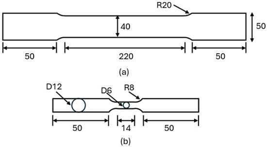
Figure 1.
Dimensions of (a) tensile and (b) cyclic coupons.
Axial cyclic loading tests were carried out on round specimens fabricated from the same SS275 plate. These specimens were prepared in accordance with ASTM E606/E606M [], with a gauge length of 14 mm and a diameter of 6 mm, as shown in Figure 1b. The tests were performed using an MTS universal testing machine under the companion loading method, wherein each specimen was subjected to a constant total strain amplitude until failure. Six specimens were tested at strain amplitudes of ±0.5%, ±1.0%, ±1.5%, ±2.0%, ±2.5%, and ±3.0%, as shown in Figure 2 corresponding to the typical strain demands experienced by seismic energy dissipation devices.
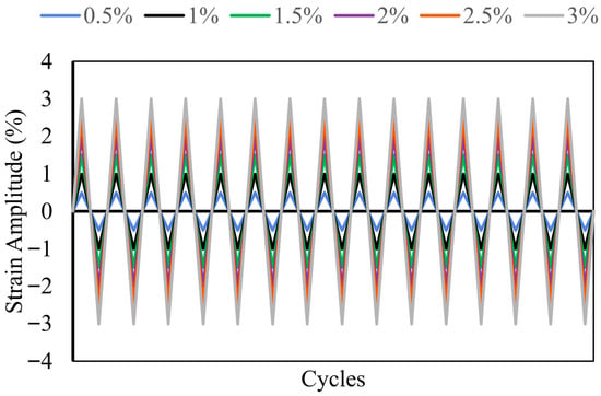
Figure 2.
Cyclic loading protocol for testing coupons.
Strain measurements were obtained using a 10 mm gauge length extensometer, as depicted in Figure 3. The cyclic loading followed a symmetric triangular waveform, applied at a constant strain rate of 0.001 s−1, and continued until fracture occurred. The fixed strain rate was applied to prevent any potential strain-rate sensitivity and to limit heat generation from plastic straining, ensuring that the experimental results reflect time-independent material behavior. The point of failure was defined as the initiation and growth of fatigue cracks at the microscopic level, eventually leading to complete fracture and a sudden loss of load-carrying capacity.
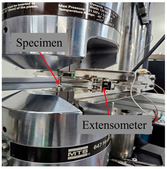
Figure 3.
Setup for cyclic coupon test.
3. Test Results and Analyses
3.1. Tensile Material Properties
The monotonic tensile tests provided essential information on the fundamental mechanical behavior of SS275 steel. The resulting engineering stress–strain curves are presented in Figure 4, and the key material properties yield strength (fy), Young’s modulus (E), ultimate tensile strength (fu), and elongation at fracture are summarized in Table 1. The variation among the three geometrically identical specimens was minimal, indicating good consistency in material behavior. The average yield strength and elongation at fracture were 328.33 MPa and 26.66%, respectively, both exceeding the minimum values specified by the Korean Standard KSD 3503 [], thereby confirming the adequacy of the material for structural applications.
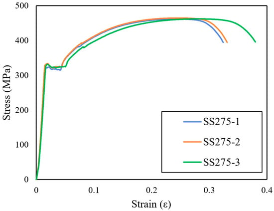
Figure 4.
Stress–strain curves from monotonic tensile tests.

Table 1.
Material properties of SS275 under monotonic loading.
3.2. Cyclic Stress–Strain Response
The cyclic behavior of SS275 steel was evaluated by subjecting each specimen to constant amplitude cyclic loading until fracture. The resulting partial hysteresis loops at various total strain amplitudes (ranging from ±0.5% to ±3.0%) are presented in Figure 5, illustrating the material’s characteristic cyclic response and energy dissipation capability. The broad and stable loops observed across the strain amplitudes indicate that SS275 possesses a strong capacity to endure and dissipate energy under repeated loading. In these plots, positive stress values (σ) represent tension, while negative values indicate compression. The first cycle of loading exhibited a stress–strain response similar to that observed in monotonic tests, with a smooth transition from elastic to plastic behavior as yielding occurred. In the purely elastic range, the stress–strain path formed a straight line, with its slope corresponding to the elastic modulus (E) of the material. After a few initial cycles, the shape of the hysteresis loops stabilized, and this steady-state response was observed to be nearly repeatable for the remainder of the test. Each strain amplitude produced a distinct set of hysteresis loops, and the number of load reversals to failure, denoted by 2Nf, varied inversely with the strain amplitude, higher amplitudes led to quicker failure. For each strain amplitude, a representative stabilized loop, typically at the half-life point, was selected to characterize the material response, as shown in Figure 6. Experimental half-life stress amplitude, elastic strain, plastic strain amplitude data was determined using the modulus-based method described in ASTM E606 [], at the loading cycles corresponding to half-life and the key values are summarized in Table 2. The cyclic stress–strain (CSS) curve could be constructed by connecting the peak stress and strain values from the stabilized loops across all tested amplitudes and can be described using the Ramberg–Osgood relationship [].
where Δε, Δεe and Δεp denote total, elastic, and plastic strain amplitudes, respectively; Δσ is the stress amplitude; E is Young’s modulus; and K′ and n′ are the cyclic strength coefficient and cyclic hardening exponent, respectively. These constants given in Table 3 were obtained through regression fitting of experimental half-life stress amplitude versus plastic strain amplitude data from Table 2 and the calibrated CSS curve based on these fitted parameters is shown in Figure 7.
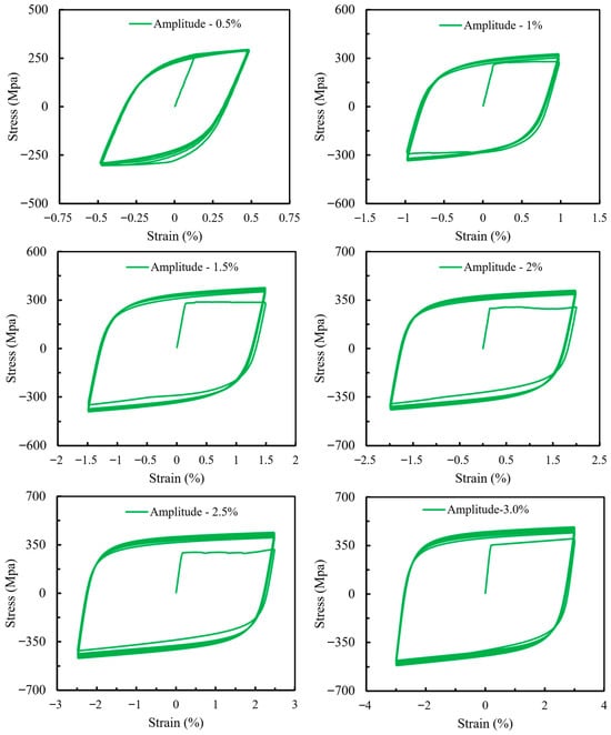
Figure 5.
Cyclic hysteretic curves of coupons.
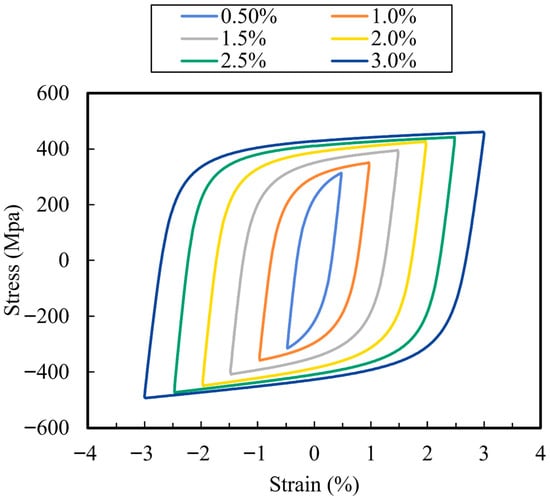
Figure 6.
Stabilized stress–strain hysteresis loops.

Table 2.
Results of cyclic loading coupon tests.

Table 3.
Coefficients for cyclic stress–strain curve and fatigue-life relationships.
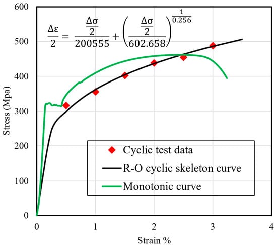
Figure 7.
Cyclic stress–strain curve.
While compared with the monotonic tensile curves, the cyclic stress–strain curve can reveal hardening or softening behavior across strain amplitudes [], as shown in Figure 7. When the applied strain amplitude is below approximately 2.5%, the cyclic curve consistently lies beneath the monotonic envelope, indicating cyclic softening. This reduction in strength under repeated small-to-moderate reversals suggests that SS275 may experience degradation in effective stiffness and resisting force when used in energy-dissipating components subjected to low-amplitude cyclic demands. As the strain amplitude increases beyond about 2.5%, the cyclic stress–strain curve begins to exceed the monotonic response, demonstrating distinct cyclic hardening. This transition reflects the material’s ability to accumulate strengthening under large inelastic excursions. For seismic energy-dissipation devices such as buckling-restrained braces (BRBs) or metallic dampers, this hardening behavior is beneficial because it enhances the capacity to sustain substantial plastic deformation without unstable degradation. The observed hardening implies improved energy dissipation per cycle at high drift levels, which is a desirable characteristic for structural components intended to protect primary framing elements during severe earthquakes.
3.3. Strain–Life Relationship
Evaluating low-cycle fatigue (LCF) behavior is essential for the reliable design of steel components subjected to repeated cyclic loading. The fatigue performance of a material is typically assessed using the strain–life approach, which is based on cyclic tests performed under constant total strain amplitudes. In this framework, fatigue damage is expressed as a combination of elastic and plastic strain components. A widely used model to describe this relationship is the Manson–Coffin–Basquin (MCB) equation [,,], which relates the total strain amplitude to the number of reversals to failure, 2Nf, using a two-term power-law expression, as shown in Equation (2):
Here, the first term represents the elastic strain component and the second term accounts for the plastic strain component, as further defined in Equations (3) and (4):
At low strain amplitudes or longer fatigue lives, the elastic strain component (Basquin relation) dominates. Conversely, at higher strain amplitudes or shorter fatigue lives, the plastic strain component (Coffin–Manson relation) becomes more significant. The parameters σ′f, b, ε′f and c correspond to the fatigue strength coefficient, fatigue strength exponent, fatigue ductility coefficient, and fatigue ductility exponent, respectively. These constants were obtained by fitting experimental data to Equations (3) and (4) using a least squares regression method and given in Table 3. Once calibrated, these parameters were used to generate the total, elastic, and plastic strain amplitude curves over a wide range of fatigue lives (expressed as 2Nf) on a log–log scale, as shown in Figure 8.
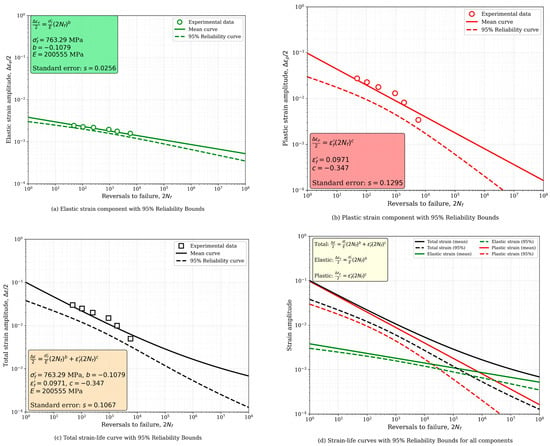
Figure 8.
Strain–life relationship curves.
3.4. Calibration of Nonlinear Constitutive Model Parameters
The Chaboche plasticity model forms the basis of many advanced constitutive formulations used for simulating the cyclic behavior of structural steels []. Due to its robust accuracy and conceptual clarity, it has been widely implemented in commercial finite element software ABAQUS 6.17 []. The model consists of two main hardening mechanisms: isotropic hardening, which accounts for changes in the size of the yield surface with accumulated plastic strain, and kinematic hardening, which governs the translation of the yield surface in stress space.
The evolution of the yield surface under isotropic hardening is defined by the following expression:
Here is the initial yield stress, Q∞ denotes the saturation limit of yield surface expansion, and biso controls the rate of isotropic hardening as a function of equivalent plastic strain εp.
To determine the size of the yield surface in the ith cycle, the following relation is used:
where and are the peak tensile and compressive stresses in the elastic range of the selected cycle, as illustrated in Figure 9a. The corresponding equivalent plastic strain for the same cycle is approximated using:
with the plastic strain amplitude Δεp estimated as:
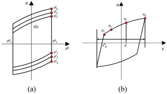
Figure 9.
Calibration of nonlinear (a) isotropic and (b) kinematic hardening components.
A set of data pairs () is generated using Equations (6) and (7), and the isotropic hardening parameters Q∞ and biso are then determined by fitting the curve through nonlinear regression.
The kinematic hardening component models the evolution of back stress α with plastic strain and is particularly applicable once the material exhibits a stable cyclic stress–strain response. The progression of α can be described by:
In this expression, represents the saturation value of back stress, while γ indicates the rate of back stress development with plastic deformation. The calibration of and is performed using data from the stabilized hysteresis loop. Back stress at a specific point is calculated as:
where is the mean of the initial and final stress values in the stabilized cycle (i.e., and ) as shown in Figure 9b.
The associated plastic strain is given by:
Here, is the initial plastic strain, typically defined as the strain intercept of the cyclic curve. The material parameters identified through this calibration process, both isotropic and kinematic, are listed in Table 4 for each tested specimen and corresponding strain amplitude and parameters from past studies are provided in Table 5.

Table 4.
Parameters of combined nonlinear isotropic–kinematic hardening Chaboche model.

Table 5.
Parameters of combined nonlinear isotropic–kinematic hardening Chaboche model from past studies.
3.5. Numerical Simulation of the Coupon’s Cyclic Behavior
The cyclic response of all tested SS275 steel coupons was simulated using the commercial finite element software ABAQUS 6.17 []. The simulations employed the nonlinear isotropic and kinematic hardening parameters listed in Table 4, which were calibrated to reproduce the experimentally observed cyclic stress–strain behavior across a range of strain amplitudes. Since the experimental hysteresis data were obtained using an extensometer with a 10 mm gauge length, the finite element (FE) model was designed as a solid cylindrical specimen with a diameter of 6 mm and a length of 10 mm, as illustrated in Figure 10. The model was discretized using structured, reduced-integration, 8-node brick elements (C3D8R). This element type was chosen due to its proven reliability in capturing accurate stress and strain responses under both tensile and compressive loading conditions. Boundary conditions were applied by fully constraining one end of the specimen in all degrees of freedom, while the opposite end was subjected to cyclic axial displacement. This displacement was applied via a reference point located at the center of the free end and was defined as the product of the prescribed strain amplitude and the extensometer gauge length (10 mm). Using the calibrated material parameters and the developed FE model, numerical simulations were carried out and the resulting stress–strain hysteresis loops were compared with the experimental results, as presented in Figure 11. The comparison demonstrates strong agreement between the numerical predictions and experimental observations, confirming the capability of the model to accurately capture the cyclic plastic behavior of SS275 steel.
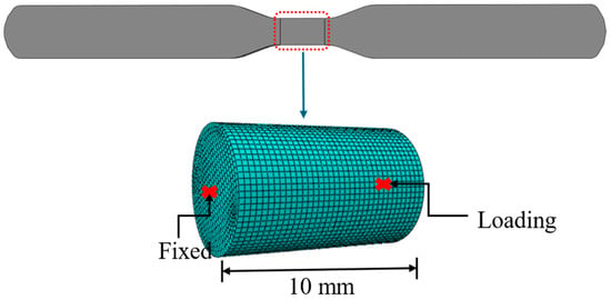
Figure 10.
Finite element modeling of cyclic coupons.
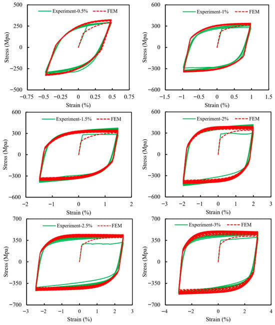
Figure 11.
Comparison of cyclic coupon’s numerical simulation with experimental results.
4. SS275 Buckling-Restrained Brace
4.1. Test Arrangement
Following the material-level investigation, this section focuses on evaluating the structural performance of SS275 steel in seismic energy dissipation applications. In recent years, buckling-restrained braces (BRBs) have emerged as a widely adopted seismic protection system due to their ability to offer stable, symmetric hysteretic behavior and enhanced energy dissipation capacity. Unlike conventional braces, BRBs are designed to prevent buckling, allowing them to yield in both tension and compression. The development of BRB technology began in Japan, with the first implementation reported by Fujimoto et al. in 1988 []. Since then, continuous research and innovation have led to significant advancements in BRB design and performance, facilitating widespread adoption across seismic-prone regions [,,,,]. A standard BRB system typically consists of three key components: (1) a metallic core, which acts as the main energy-dissipating element by undergoing axial plastic deformation, (2) a restraining mechanism, designed to prevent local and global buckling of the core under compressive loading, (3) debonding layer placed between the core and the restraining unit to reduce friction and accommodate lateral expansion due to Poisson’s effect. In this study, a reduced-scale experimental test was conducted on an all-steel BRB fabricated from Korean-made SS275 steel. The prototype BRB features a dog-bone-shaped steel core, enclosed between two restraining and filling plates, which are assembled using bolts, allowing for straightforward inspection and core replacement following seismic events (as shown in Figure 12). The BRB core was fabricated as a monolithic component that includes connection ends, transition regions, and a central yielding segment. To limit unwanted relative movement between the core and its casing during both installation and loading, stopper were introduced by increasing the width at designated central locations. For improved load transfer and to reduce the risk of premature failure, a pair of longitudinal stiffeners (320 mm in length and matching the core’s thickness) were welded at both ends of the yielding section. Additionally, 30 mm thick end plates were attached at each end to facilitate installation within the testing apparatus.
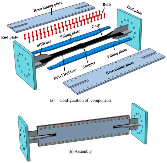
Figure 12.
Details of SS275-BRB.
The core plate, stiffeners, and end plates fabricated from SS275 carbon steel were welded using the shielded metal arc Welding (SMAW) process in accordance with a qualified welding procedure specification (WPS). A low-hydrogen E7018 electrode (AWS A5.1) was employed due to its good toughness and compatibility with structural carbon steels; the deposited metal contains Fe–Mn–Si alloying elements with an approximate chemical composition of C ≤ 0.15%, Mn 0.9–1.6%, Si 0.3–0.8%, S ≤ 0.035%, and P ≤ 0.035%. Prior to welding, all surfaces were cleaned and a preheat temperature of 50–75 °C was applied to reduce the risk of hydrogen-induced cracking. Welding was performed in the flat (1G/1F) position under the following WPS parameters: current 110–150 A (DC+), voltage 20–26 V, travel speed 90–120 mm/min, and an interpass temperature limit of 150 °C. Stiffeners and end plates were joined using 8 mm fillet welds, deposited as multi-pass beads along both sides of the joints to ensure full fusion and structural integrity.
The restraining unit comprised a pair of flat external plates and two intermediate filler plates, all securely fastened using M12 high-strength bolts (Grade 10.9) placed at 50 mm intervals. This bolted configuration was designed to ensure out-of-plane restraint of the core and allow for easy assembly and disassembly. To minimize friction between the core and its restraining elements, a 1 mm thick butyl rubber sheet was inserted as a debonding layer. Detailed geometric dimensions of the BRB assembly are provided in Figure 13. The total length of the test specimen was 1400 mm, including a 760 mm long yielding zone. The core plate had a thickness of 10 mm and a tapered width, transitioning from 120 mm at the ends to 60 mm in the yielding region.
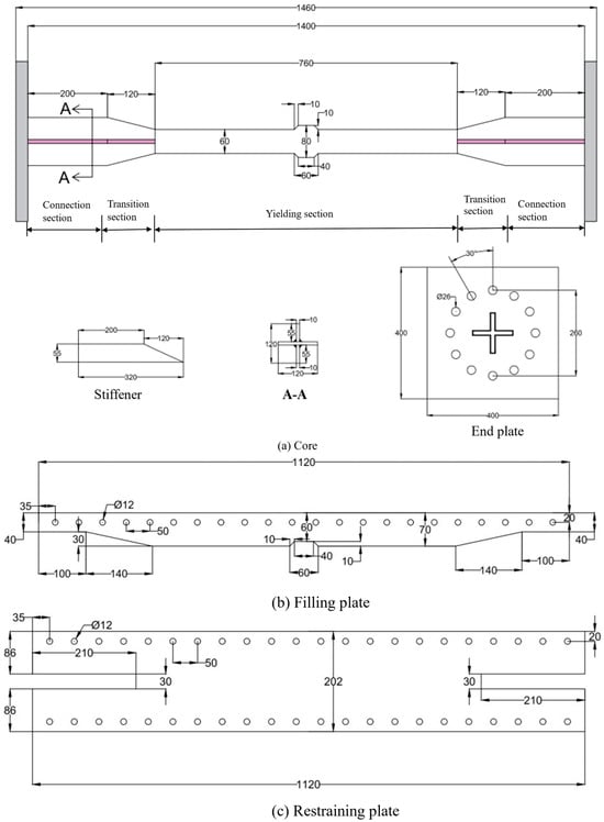
Figure 13.
Dimensions of SS275-BRB.
The experimental setup, shown in Figure 14, was organized at Korea Conformity Laboratories. The BRB specimens were mounted horizontally using M24 high-strength bolts. Cyclic loading was applied from one end using a displacement-controlled hydraulic actuator with a maximum capacity of ±800 kN and ±250 mm displacement. Axial force and displacement data were captured using an integrated data acquisition (DAQ) system.
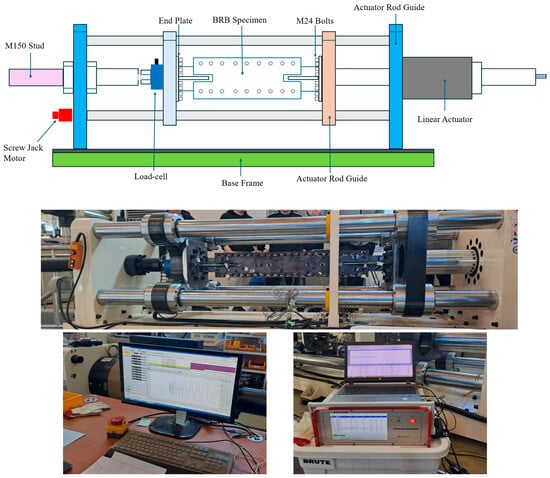
Figure 14.
Test setup and data acquisition system of BRB-experiment.
The selection of loading conditions plays a critical role in evaluating the cyclic performance and failure mechanisms of Buckling-Restrained Braces (BRBs). Various international codes and standards have proposed specific protocols for BRB testing to ensure consistent performance assessment []. In this study, the experimental procedure followed the standardized BRB testing protocol widely adopted in Japan []. This protocol was selected in light of the increased seismic activity observed on the Korean Peninsula following the 2011 Tohoku-Oki earthquake (Mw 9.0), which marked a significant shift in regional seismicity. Notably, the frequency of earthquakes exceeding magnitude 5.0 in Korea has risen beyond the levels recorded over the previous five decades of modern seismic observation [].
The applied loading sequence involved three full cycles at the yield displacement level (Δy), followed by incrementally increasing strain amplitudes ranging from 0.5% up to 3.0% axial strain. The test was continued until the BRB core fractured at a final plastic strain amplitude of 3.0%. As illustrated in Figure 15, the protocol began with two initial elastic cycles at amplitudes of 1/3Δy and 2/3Δy. These preliminary cycles were conducted to assess the axial stiffness of the specimen in the elastic range and to verify the performance of the loading system.
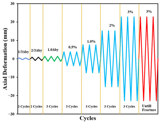
Figure 15.
Loading protocol for BRB-experiment.
A displacement-controlled loading rate of 0.1 mm/s was used during the initial elastic cycles to ensure precise stiffness evaluation. Once yielding was initiated, the loading rate was increased to 0.5 mm/s, which was maintained consistently throughout the remaining test cycles until failure.
4.2. Results and Discussion
Throughout the testing process, no signs of global or local buckling, bolt slippage, or structural instability were observed. After the completion of the experiment, BRB assembly was disassembled to inspect the failure mechanisms of the internal core, as illustrated in Figure 16. The failure primarily occurred in tension, with fracture initiating near the interface between the yielding segment and the stopper regions, consistent with findings reported for similar core geometries [,]. While no apparent signs of higher-mode buckling were observed, physical evidence of tearing, surface scraping, and pronounced frictional marks were present along the unbonded interface of core at various locations, indicating localized interaction between the core and restraining components.
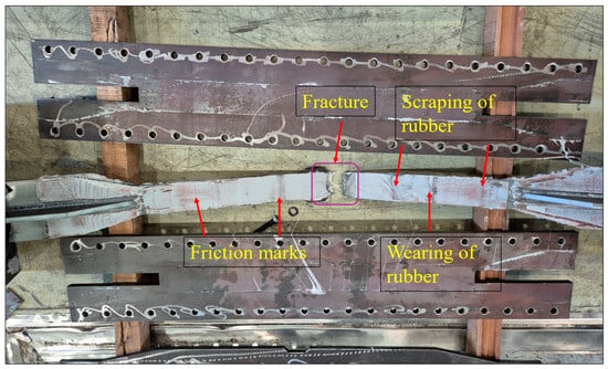
Figure 16.
Failure mode of BRB after experiment.
The axial force–displacement response of the BRB specimen is plotted in Figure 17. In this figure, axial displacement and the corresponding core strain calculated as the ratio of axial displacement to the yielding length are shown on the upper and lower X-axes, respectively. Positive values indicate tensile forces, displacements, and strains, while negative values correspond to compressive behavior. The red triangle on the plot marks the fracture point, representing the peak load capacity of the specimen before failure.
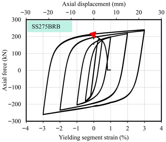
Figure 17.
Hysteretic curve of BRB.
The tested SS275 BRB demonstrated stable, repeatable hysteretic behavior throughout the loading history. The force–displacement loops remained full and symmetric, with no indication of strength or stiffness degradation, confirming the brace’s effectiveness in dissipating energy under cyclic loading.
4.3. Seismic Performance
4.3.1. Compression Strength Adjustment Factor (β)
In general, the maximum compressive force (Cmax) developed in a buckling-restrained brace (BRB) tends to exceed the maximum tensile force (Tmax) due to the additional contact forces generated between the core and the surrounding restraining elements during compression. To quantify this difference and evaluate the brace’s uniformity under tension and compression, the compression strength adjustment factor (β) was calculated using Equation (12).
The values of Cmax, Tmax, and the corresponding β are summarized in Table 6. The calculated β = 1.08 factor satisfied the design code requirement [], which stipulates that β must not exceed 1.3, indicating a balanced axial behavior under both loading directions.

Table 6.
Seismic performance of SS275-BRB.
4.3.2. Energy Dissipation Capacity
The equivalent viscous damping ratio (ξeq) serves as a key parameter in assessing the energy dissipation efficiency of BRBs during cyclic loading. This ratio was calculated based on Equation (13):
where Aloop represents the area enclosed by each hysteresis loop. Tmax and Cmax, denote the peak tensile and compressive forces corresponding to the maximum tensile (Δtm) and compressive (Δcm) displacements in each cycle, respectively. The variation in ξeq across all loading cycles is illustrated in Figure 18, while the value corresponding to the maximum loading cycle is reported in Table 6. The results demonstrate the effective energy dissipation behavior of the tested BRB.
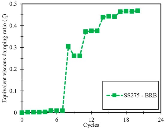
Figure 18.
Equivalent viscous damping ratios (ξeq).
4.3.3. Cumulative Plastic Deformation (CPD)
To evaluate the inelastic deformation capacity of the BRB specimen, the Cumulative Plastic Deformation (CPD) coefficient was computed using Equation (14).
This metric captures the total plastic deformation accumulated over all cycles, normalized by the yield displacement of the brace. Specifically, Δtmax and Δcmax refer to the maximum tensile and compressive axial displacements observed in each cycle before failure, while Δy represents the experimentally determined yield displacement.
According to the seismic design provisions of AISC [], a CPD value of at least 200 is recommended to ensure sufficient ductility and inelastic deformation capacity in BRBs to prevent early failure. The calculated CPD for the tested specimen, reported in Table 6, exceeded this threshold, confirming its excellent plastic deformation performance under cyclic loading.
4.4. Numerical Simulation of SS275 BRB
A finite element (FE) model of the tested buckling-restrained brace (BRB) was developed based on the exact geometry of the experimental specimen, with the primary objective of validating the calibrated cyclic model material parameters and ensuring the model could accurately reproduce the observed hysteretic behavior of the SS275 BRB. The numerical analysis was carried out using ABAQUS 6.17 [], where all key components including the steel core, restraining plates, and filler plates were modeled using eight-node 3D solid elements (C3D8R). The end plates, which were only used to fix the specimen in the experimental setup, were excluded from the simulation to reduce computational complexity. Although the restraining assembly was physically connected with 8.8-grade high-strength bolts in the test, the plates remained elastic throughout the loading process. To improve computational efficiency, tie constraints were applied instead of explicitly modeling the bolt connections. Contact interactions between the core and restraining components were modeled using surface-to-surface contact. Normal contact behavior was defined as “hard contact,” while the tangential behavior was modeled using the penalty method. A low friction coefficient of 0.1 was applied at the interface between the lubricated core and the restraining plates reflecting the presence of butyl rubber as commonly adopted in similar studies by Chou & Chen [] and Hoveidae & Rafezya []. For other component interfaces, a friction coefficient of 0.3 was used. Boundary conditions and loading protocol were applied using reference points coupled to the end faces of the BRB. These reference points were constrained against translations in the X and Y directions, and all rotational degrees of freedom were fixed. Axial displacement in the Z-direction was applied to replicate the same loading condition as used in the experiment, described in Figure 19a. To reflect geometric imperfections arising from fabrication tolerances, initial geometric defects were incorporated into the model. An eigenvalue buckling analysis was first performed to extract the fundamental buckling mode of the core. This mode shape was then scaled to a magnitude of L/1000 (where L is the total BRB length) and applied as the initial imperfection shape in the model, as illustrated in Figure 19b. Nonlinear static analysis was conducted using the Newton-Raphson iterative method, with the analysis step configured to have a maximum increment of 0.1 and a minimum increment of 1 × 10⁻³⁰ to ensure convergence. The combined isotropic and kinematic hardening model available in ABAQUS was used to represent the cyclic plastic behavior of the SS275 core. The model employed material parameters calibrated from the ±3% strain amplitude coupon test, including σ0 = 244.22 MPa, Q∞ = 76.04 MPa, and b = 1.372. While the cyclic coupon test could be accurately simulated using a single set of kinematic hardening parameters, replicating the BRB response under higher amplitude seismic loading required splitting the kinematic hardening into three components: C1 = 9800 MPa with γ1 = 250, C2 = 6500 MPa with γ2 = 85, and C3 = 3290 MPa with γ3 = 70. This division was necessary to capture both the rapid initial hardening and the gradual evolution of plasticity across multiple deformation stages, enabling a more accurate simulation of the BRB’s stable hysteretic behavior during large displacement cycles. Following a mesh sensitivity analysis, the element sizes in the longitudinal direction were set as follows: 5 mm for the core, 6 mm for the filler plates, and 8 mm for the restraining plates, ensuring a balance between accuracy and computational efficiency.
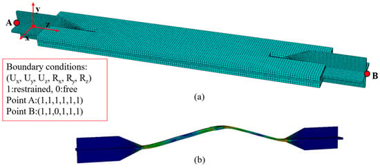
Figure 19.
Finite element model of BRB; (a) Boundary conditions (b) initial imperfection shape.
4.5. Model Validation
Figure 20 illustrates the comparison between the hysteresis loops obtained from the finite element (FE) simulation and the experimental test of the BRB specimen. The numerical model effectively captured the overall cyclic behavior across varying strain amplitudes, closely matching the experimental results. Both the strength and stiffness responses during loading and unloading phases were well replicated by the simulation, demonstrating the reliability of the calibrated model. To further investigate internal stress behavior, the same FE model was used to extract the stress distribution within the BRB core during the tensile half-cycle of the 22.8 mm axial displacement, as shown in Figure 21. The simulation results confirm the intended stress transmission path, starting from the connection segment, passing through the transition region, and concentrating in the yielding segment. As expected, the stress was lowest in the connection zone and highest in the yielding zone, where plastic deformation was most pronounced. Overall, the numerical results validate that the FE model, employing the calibrated nonlinear material parameters, is capable of accurately reproducing the seismic behavior of the SS275 BRB, including key features such as stress localization and inelastic deformation zones.
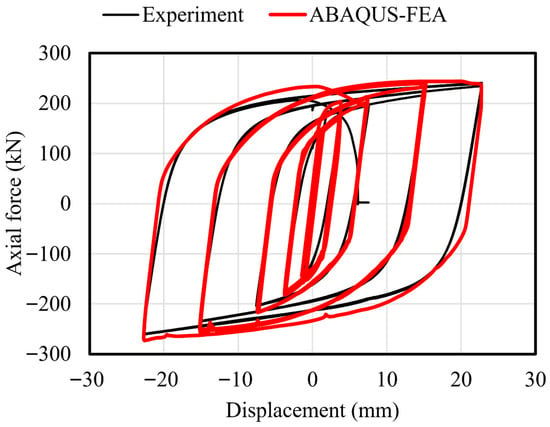
Figure 20.
Comparison of BRB test and FEA.

Figure 21.
Stress distribution in core component.
5. Conclusions
This study conducted a comprehensive experimental and numerical investigation to evaluate the low-cycle fatigue performance and constitutive modeling of Korean-manufactured SS275 steel. Uniaxial tensile tests and fully reversed strain-controlled cyclic tests were carried out at strain amplitudes of ±0.5%, ±1.0%, ±1.5%, ±2.0%, ±2.5%, and ±3.0%. In addition, a reduced-scale buckling-restrained brace (BRB) specimen made from SS275 was tested under a standardized cyclic loading protocol relevant to seismic qualification. Based on the outcomes of the material and structural-level tests, as well as finite element analyses, the following conclusions are drawn:
- The monotonic tensile behavior of SS275 steel was consistent across all three tested specimens. The average values for yield strength (328.33 MPa), Young’s modulus (226.33 MPa), ultimate tensile strength (461.33 MPa), and elongation at fracture (26.66%) all exceeded the minimum requirements specified by Korean Standard KSD 3503, confirming the material’s suitability for structural applications.
- Under strain-controlled cyclic loading, the material exhibited stable and full hysteresis loops across all amplitude levels, indicating excellent energy dissipation capability of SS275 steel.
- The cyclic stress–strain relationship was accurately characterized using the Ramberg–Osgood model, which provided a strong fit to the experimental data and effectively captured the gradual hardening behavior under increasing strain.
- The strain–life behavior of SS275 was described using parameters derived from the Coffin–Manson–Basquin (CMB) model. The results indicated that fatigue life was more sensitive to plastic strain than to elastic strain, confirming the limited influence of elastic strain amplitude in the low-cycle fatigue regime.
- The Chaboche combined isotropic–kinematic hardening model parameters were calibrated using cyclic coupon test data and validated through finite element simulations in ABAQUS. The model showed good agreement with experimental results and accurately represented the nonlinear cyclic response of the material.
- Extending the material-level findings, a reduced-scale buckling-restrained brace (BRB) specimen made from SS275 steel was experimentally tested to evaluate its seismic performance, and a corresponding finite element model was developed using the calibrated cyclic material parameters.
- The BRB numerical model successfully replicated the experimental cyclic response over a range of loading amplitudes. The simulation results closely matched the experimental force–displacement response, confirming that the model effectively captured the seismic behavior and energy dissipation characteristics of the SS275-based BRB.
Limitations
The present work was conducted using only one instance of heating SS275 structural steel, which is a Korean-standard material. Therefore, the computed cyclic stress–strain relationship, fatigue-life properties, and Chaboche model parameters are specific to this steel and may not be directly applicable to other steels of similar grades or compositions. The potential influence of material variability on cyclic and fatigue behavior should be further investigated in future work.
Author Contributions
H.H.: Conceptualization, Data curation, Formal analysis, Investigation, Methodology, Software, Visualization, Writing—original draft. D.-k.K.: Conceptualization, Funding acquisition, Project administration, Supervision, Validation, Writing—review and editing. All authors have read and agreed to the published version of the manuscript.
Funding
This work was supported by the Basic Science Research Program through the National Research Foundation (NRF) funded by the Korea Ministry of Education (No. 2022R1F1A1076048).
Data Availability Statement
Data will be made available on request.
Conflicts of Interest
The authors declare no conflicts of interest.
References
- Almajhali, K.Y.M.; He, M.; Alhaddad, W. Enhancing seismic performance of structures: A comprehensive review of hybrid passive energy dissipation devices. Structures 2024, 69, 107223. [Google Scholar] [CrossRef]
- Titirla, M.D. A State-of-the-Art Review of Passive Energy Dissipation Systems in Steel Braces. Buildings 2023, 13, 851. [Google Scholar] [CrossRef]
- Li, C.; Peng, Y.; Yang, P.; Xiao, K. Experimental Study on a UHPC Precast Pier with External Energy Dissipation Device for Seismic Resilience. Buildings 2025, 15, 3272. [Google Scholar] [CrossRef]
- Nip, K.H.; Gardner, L.; Davies, C.M.; Elghazouli, A.Y. Extremely low cycle fatigue tests on structural carbon steel and stainless steel. J. Constr. Steel Res. 2010, 66, 96–110. [Google Scholar] [CrossRef]
- Wang, N.; Li, W.B.; Zou, C.L.; Pang, J.C.; Chen, L.J.; Gao, C.; Zheng, S.J.; Li, S.X.; Zhang, H.; Zhang, Z.F. Low cycle fatigue properties and life prediction of selective laser melted Inconel 718 at different temperatures. J. Mater. Res. Technol. 2025, 35, 1829–1841. [Google Scholar] [CrossRef]
- Narendra, P.V.R.; Prasad, K.; Krishna, E.H.; Kumar, V.; Singh, K.D. Low-Cycle-Fatigue (LCF) behavior and cyclic plasticity modeling of E250A mild steel. Structures 2019, 20, 594–606. [Google Scholar] [CrossRef]
- Tremblay, R.; Filiatrault, A.; Timler, P.; Bruneau, M. Performance of steel structures during the 1994 Northridge earthquake. Can. J. Civ. Eng. 1995, 22, 338–360. [Google Scholar] [CrossRef]
- Fang, C.; Wang, W.; Qiu, C.; Hu, S.; MacRae, G.A.; Eatherton, M.R. Seismic resilient steel structures: A review of research, practice, challenges and opportunities. J. Constr. Steel Res. 2022, 191, 107172. [Google Scholar] [CrossRef]
- Dusicka, P.; Itani, A.M.; Buckle, I.G. Cyclic response of plate steels under large inelastic strains. J. Constr. Steel Res. 2007, 63, 156–164. [Google Scholar] [CrossRef]
- Dehghani, M.; Tremblay, R.; Leclerc, M. Fatigue failure of 350WT steel under large-strain seismic loading at room and subfreezing temperatures. Constr. Build. Mater. 2017, 145, 602–618. [Google Scholar] [CrossRef]
- Annan, C.-D.; Beaumont, E. Low-cycle fatigue of stainless steel plates under large plastic strain demands. J. Build. Eng. 2020, 29, 101160. [Google Scholar] [CrossRef]
- Chen, Y.; Sun, W.; Chan, T.-M. Effect of Loading Protocols on the Hysteresis Behaviour of Hot-Rolled Structural Steel with Yield Strength up to 420 MPa. Adv. Struct. Eng. 2013, 16, 707–719. [Google Scholar] [CrossRef]
- Shi, Y.; Wang, M.; Wang, Y. Experimental and constitutive model study of structural steel under cyclic loading. J. Constr. Steel Res. 2011, 67, 1185–1197. [Google Scholar] [CrossRef]
- Zhong, Y.-L.; Wang, Y.-B.; Xiang, Y.; Li, G.-Q. Constitutive model for cyclic behavior of mild steel under various strain amplitudes. J. Constr. Steel Res. 2022, 196, 107396. [Google Scholar] [CrossRef]
- Krolo, P.; Grandić, D.; Smolčić, Ž. Experimental and Numerical Study of Mild Steel Behaviour under Cyclic Loading with Variable Strain Ranges. Adv. Mater. Sci. Eng. 2016, 2016, 1–13. [Google Scholar] [CrossRef]
- Liao, X.; Wei, H.; Feng, L.; Ban, H. Low-cycle fatigue behavior for stainless-clad 304 + Q235B bimetallic steel. Int. J. Fatigue 2022, 159, 106831. [Google Scholar] [CrossRef]
- Hai, L.-T.; Sun, F.-F.; Zhao, C.; Li, G.-Q.; Wang, Y.-B. Experimental cyclic behavior and constitutive modeling of high strength structural steels. Constr. Build. Mater. 2018, 189, 1264–1285. [Google Scholar] [CrossRef]
- Shi, G.; Wang, M.; Bai, Y.; Wang, F.; Shi, Y.; Wang, Y. Experimental and modeling study of high-strength structural steel under cyclic loading. Eng. Struct. 2012, 37, 1–13. [Google Scholar] [CrossRef]
- Wang, Y.Q.; Chang, T.; Shi, Y.J.; Yuan, H.X.; Yang, L.; Liao, D.F. Experimental study on the constitutive relation of austenitic stainless steel S31608 under monotonic and cyclic loading. Thin-Walled Struct. 2014, 83, 19–27. [Google Scholar] [CrossRef]
- Cho, Y.; Kim, T.; Kim, J.; Lee, D. Block Shear Strength of Double-Lap Welded Connections in Mild Carbon Steel Plate. Int. J. Steel Struct. 2021, 21, 1894–1909. [Google Scholar] [CrossRef]
- Kim, J.; Cho, Y.; Kim, T. Recommendation on block shear strength equation of double shear four-bolted connection in cold-formed mild carbon steel. Structures 2021, 33, 3713–3735. [Google Scholar] [CrossRef]
- Park, H.-Y.; Oh, S.-H. Structural performance of beam system with T-stub type slit damper. Eng. Struct. 2020, 205, 109858. [Google Scholar] [CrossRef]
- Lee, K.-S.; Lee, B.-G.; Jung, J.-S. Nonlinear dynamic response of R/C buildings strengthened with novel stud-typed seismic control system using non-buckling slit damper. Eng. Struct. 2021, 244, 112749. [Google Scholar] [CrossRef]
- Park, H.-Y.; Oh, S.-H. Design range of the damper of a T-stub damage-controlled system. J. Constr. Steel Res. 2019, 162, 105719. [Google Scholar] [CrossRef]
- Kim, J.; Kwon, U.-J.; Park, H.-Y.; Kim, Y.-J.; Kim, J.-B. Experimental Study on the Dynamic Characteristics of Steel Slit Dampers with and Without Out-of-Plane Deformation Restraints. Int. J. Steel Struct 2024, 24, 958–968. [Google Scholar] [CrossRef]
- Hwang, B.; Kim, T.; Kim, Y.; Kim, J. A comparative study on hysteretic characteristics of austenitic stainless steel and carbon steel slit dampers under cyclic loading. J. Build. Eng. 2022, 45, 103553. [Google Scholar] [CrossRef]
- Hwang, B.; Kim, T.; Ahn, Y. Experimental investigation of structural behavior of 316L stainless steel and carbon steel slit dampers. Thin-Walled Struct. 2023, 186, 110704. [Google Scholar] [CrossRef]
- Cho, Y.; Lee, C.; Yee, J.-J.; Kim, D.-K. Modeling of Ductile Fracture for SS275 Structural Steel Sheets. Appl. Sci. 2021, 11, 5392. [Google Scholar] [CrossRef]
- Cho, E.; Hyun, J.; Han, S.W. Estimation of combined hardening model parameter values for Korean steel grades. In Proceedings of the 2020 World Congress on Advances in Civil, Environmental, & Materials Research (ACEM20), GECE, Seoul, Republic of Korea, 25–28 August 2020. [Google Scholar]
- Han, S.W.; Hyun, J.; Cho, E.; Lee, K. Efficient determination of combined hardening parameters for structural steel materials. Steel Compos. Struct. 2022, 42, 657–669. [Google Scholar] [CrossRef]
- KS B 0802; Method of Tensile Test for Metallic Materials. Korean Standard (KS): Seoul, Republic of Korea, 2003.
- ASTM, E8/E8M-09; Standard Test Methods for Tension Testing of Metallic Materials. ASTM International: West Conshohocken, PA, USA, 2009.
- ASTM, E606–04e1; Standard Practice for Strain-Controlled Fatigue Testing. ASTM International: West Conshohocken, PA, USA, 2004.
- KS D 3503; Rolled Steels for General Structure. Korean Standard (KS): Seoul, Republic of Korea, 2018. (In Korean)
- Ramberg, W.; Osgood, W.R. Description of Stress–Strain Curves by Three Parameters; Technical Note No. 902; National Advisory Committee on Aeronautics: Washington, DC, USA, 1943. [Google Scholar]
- Basquin, O.H. The exponential law of endurance tests. Am. Soc. Test. Mater. 1910, 10, 625–630. [Google Scholar]
- Coffin, L.F. A study of the effect of cyclic thermal stresses on a ductile metal. Trans. ASME 1954, 76, 931–950. [Google Scholar] [CrossRef]
- Manson, S.S. Behavior of materials under conditions of thermal stress. In Heat Transfer Symposium, University of Michigan; University of Michigan Press: Ann Arbor, MI, USA, 1953. [Google Scholar]
- Chaboche, L. Time independent constitutive theories for cyclic plasticity. Int. J. Plast. 1986, 2, 149–188. [Google Scholar] [CrossRef]
- Hai, L.; Wang, Y.; Ban, H.; Li, G.; Du, X. A simplified prediction method on Chaboche isotropic/kinematic hardening model parameters of structural steels. J. Build. Eng. 2023, 68, 106151. [Google Scholar] [CrossRef]
- ABAQUS. Analysis User’s Manual I–V; Version 6.17; ABAQUS, Inc., Dassault Systems: Waltham, MA, USA, 2017. [Google Scholar]
- Fujimoto, A.W.M.; Saeki, E.; Watanabe, A.; Hitomi, Y. A study on the unbonded brace encased in buckling-restraining concrete and steel tubes. J. Struct. Constr. Eng (Trans. AIJ) 1988, 34B, 249–258. (In Japanese) [Google Scholar]
- Zhou, Y.; Shao, H.; Cao, Y.; Lui, E.M. Application of buckling-restrained braces to earthquake-resistant design of buildings: A review. Eng. Struct. 2021, 246, 112991. [Google Scholar] [CrossRef]
- Wu, K.; Wei, G.; Lin, C.; Zhang, L.; Yu, W.; Lan, X. Experimental Study on the Seismic Performance of Buckling-Restrained Braces with Different Lengths. Buildings 2025, 15, 154. [Google Scholar] [CrossRef]
- Wu, K.; Wei, G.; Zhang, L.; Yu, W.; Lan, X. Experimental Study on the Seismic Behavior of All-Steel Buckling-Restrained Braces Without an Unbonded Material Layer. Buildings 2025, 15, 1626. [Google Scholar] [CrossRef]
- Lin, Y.; Zhou, Z.; Shen, M.; Liu, J.; Huang, W. Experimental Study of a New Self-Centering BRB and Its Application in Seismic Resistance of Frame Structure. Buildings 2024, 14, 850. [Google Scholar] [CrossRef]
- Huang, H.; Wang, J.; Yao, D.; Zhou, P.; Zhao, S. SMA-Activated Double-Stage Yielding BRB: Experimental and FEM Insights. Buildings 2025, 15, 3225. [Google Scholar] [CrossRef]
- Chen, H.; Bai, J. Loading protocols for seismic performance evaluation of buckling-restrained braces in RC frames. J. Build. Eng. 2022, 45, 103522. [Google Scholar] [CrossRef]
- The Building Center of Japan (BCJ). Specifications for BRB Certification (BCJ-16); The Building Center of Japan: Tokyo, Japan, 2017. [Google Scholar]
- Malehmir, A.; Hong, T.-K.; Lee, J.; Zappalá, S.; Brodic, B.; Chung, D.; Kim, B.; Park, S.; Lee, J.; Kil, D. Fault intersections control short period intraplate start-stop seismicity in the Korean Peninsula. Tectonophysics 2022, 834, 229387. [Google Scholar] [CrossRef]
- Xiong, C.; Cao, Y.; Wang, T.; Xie, L.; Wu, D. Experimental and numerical studies of a core plate repairable double-stage yield buckling-restrained brace. J. Constr. Steel Res. 2024, 223, 109006. [Google Scholar] [CrossRef]
- Yun, Z.; Cao, Y.; Takagi, J.; Zhong, G.; He, Z. Experimental and numerical investigation of a novel all-steel assembled core-perforated buckling-restrained brace. J. Constr. Steel Res. 2022, 193, 107288. [Google Scholar] [CrossRef]
- ANSI/AISC 341-16; Seismic Provisions for Structural Steel Buildings. American Institute of Steel Construction: Chicago, IL, USA, 2016.
- Chou, C.-C.; Chen, S.-Y. Subassemblage tests and finite element analyses of sandwiched buckling-restrained braces. Eng. Struct. 2010, 32, 2108–2121. [Google Scholar] [CrossRef]
- Hoveidae, N.; Rafezy, B. Overall buckling behavior of all-steel buckling restrained braces. J. Constr. Steel Res. 2012, 79, 151–158. [Google Scholar] [CrossRef]
Disclaimer/Publisher’s Note: The statements, opinions and data contained in all publications are solely those of the individual author(s) and contributor(s) and not of MDPI and/or the editor(s). MDPI and/or the editor(s) disclaim responsibility for any injury to people or property resulting from any ideas, methods, instructions or products referred to in the content. |
© 2025 by the authors. Licensee MDPI, Basel, Switzerland. This article is an open access article distributed under the terms and conditions of the Creative Commons Attribution (CC BY) license (https://creativecommons.org/licenses/by/4.0/).