Abstract
Owing to the light-transmitting, energy-saving, and load-bearing properties of glass, laminated glass has gradually been adopted as vehicle lane surfaces in scenarios such as multi-storey commercial complexes, glass walkways roads, and underground parking lots. However, currently, a mature design system for vehicle-borne glass bridge decks is still lacking, and the existing design system for pedestrian glass bridge decks cannot be directly applied to vehicle-borne scenarios. Combining domestic and international specifications and research, this study focused on material selection, structural configuration, and structural calculation of vehicle-borne glass bridge decks, proposed a targeted design method, and verified it with engineering examples. The key conclusions are as follows: (1) Laminated glass for bridge decks should preferably use homogenized tempered glass with SGP as the interlayer material; the number of glass layers should be controlled between 3 and 5, the aspect ratio of glass panels should be maintained between 1 and 2, the thickness of a single glass panel should not be less than 8 mm, and the interlayer thickness should be between 0.76 mm and 2.28 mm. (2) This study proposes design loads, load combination methods, calculation models, design criteria, and the equivalent thickness calculation method for vehicle-borne glass bridge decks; meanwhile, it incorporates the adverse working condition of single-layer glass breakage into design considerations. (3) The design method shows good agreement with numerical simulation results: both PVB and SGP-laminated glass can meet the load-bearing capacity requirements, but SGP-laminated glass has a larger safety redundancy under the same thickness; after single-layer glass breakage, the bridge deck still has sufficient load-bearing capacity; the calculation results of the design method are slightly more conservative than the finite element calculation results, but the calculation of stress and deflection for SGP-laminated glass is relatively accurate. (4) Future research will further deepen the study on the impact of the long-term performance of laminated glass on the full-life-cycle of vehicle-borne glass bridge decks and improve this design method.
1. Introduction
The use of glass dates back to ancient civilizations [1]. Due to its high light transmittance, it has been widely used in scenarios such as glass curtain walls and basements. However, glass itself has high brittleness, sensitivity to concentrated stress, and low crack tolerance, which limit its application as a load-bearing structure. The emergence of laminated glass has alleviated this issue to a certain extent. In recent years, relying on its excellent performance, laminated glass has been widely applied in building structures such as multi-storey commercial complexes, glass walkways, and underground parking lots—including the Yuntiandu Glass Bridge in Zhangjiajie Grand Canyon, the cantilevered glass viewing corridor bridge at Longgang, Yunyang, Chongqing, and the Tianmen Mountain Glass Plank Road. These structures provide a unique viewing experience.
Research on glass load-bearing structures and laminated composite materials has been increasingly conducted in recent years. Hänig et al. [2] proposed a type of glass–plastic composite panel, whose load-bearing performance is close to that of monolithic glass with the same thickness, while significantly reducing self-weight and improving stiffness. Zhang [3] conducted in-plane shear tests on laminated glass panels with elastic support on opposite sides, and revealed the influence of the laws of the in-plane constraint stiffness of structural adhesive and glass type on the ultimate shear bearing capacity and deformation of glass panels. Adam et al. [4] established a calculation model for stress and deflection of glass bridge decks under pedestrian loads based on European standards, and emphasized the key influence of polymer interlayers on panel performance. Qing et al. [5] used the meshless radial point interpolation method with Kronecker function characteristics to discretize the control equations derived from the Higher-Order Shear Deformation Theory (HSDT), and analyzed the causes of interlayer damage in laminated plate structures. Tomasz et al. [6] fabricated main box girders with U-shaped cross-sections and bridge decks using Vacuum-Assisted Resin Transfer Molding (VARTM)-infused glass–carbon composite materials; static loading tests showed that the full-scale girder structures had good performance, and were in reasonable agreement with the finite element design and analysis predictions. Liu [7] carried out a series of in-depth studies on the bending performance of laminated glass. Chiara et al. [8] measured the basic dynamic parameters of an existing pedestrian glass suspension bridge through tests, and then used finite element software to further evaluate the structural performance. However, there are relatively few technical standards for glass load-bearing structures at home and abroad at present. In 2018, Hebei Province issued the Technical Standard for Pedestrian Glass Suspension Bridges and Glass Plank Roads in Scenic Areas (DB 13(J)/T 264-2018) [9], the first specification for glass plank roads in China. This standard, which draws on the Technical Specification for Application of Building Glass (JGJ 113-2015), specifies the materials, structural systems, and calculation methods of glass bridges.
The engineering application and establishment of technical standards for pedestrian glass bridge decks have greatly promoted the exploration and development of vehicle-borne glass structures. Chen [10] et al. conducted research on the mechanical properties of four-sided simply supported tempered laminated glass panels under local uniformly distributed loads; they found that there exists an economic glass thickness range for glass panel thickness, and simultaneously proposed an equivalent thickness calculation formula for laminated glass based on equal maximum stress. Tang et al. [11,12,13] carried out bearing capacity tests on three-layer laminated glass bridge decks under different wheel pressure loads, as well as studies on the bearing capacity and deflection of vehicle-borne glass bridge decks under different boundary conditions; they also used Digital Image Correlation (DIC) technology to measure the out-of-plane deflection displacement field of laminated glass panels under lateral loads, and explored the static response of multi-layer laminated glass bridge decks under wheel pressure. Cheng et al. [14] established an analytical equation system using the Navier method based on the thin plate large-deflection bending theory, and derived theoretical calculation formulas for parameters such as deflection, stress, and bending moment of glass bridge decks under local loads. Li et al. [15] solved the theoretical solutions for bending deformation and internal force of glass bridge decks under wheel pressure loads using the double trigonometric series method based on the thin plate small-deflection bending theory, which were verified by experiments and finite element analysis.
Scholars at home and abroad have conducted in-depth studies on the mechanical characteristics, analysis methods, and load-bearing performance of vehicle-borne glass panel structures; however, a mature systematic design theory and method for vehicle-borne glass bridge decks are still lacking at present. The existing design system for pedestrian glass bridge decks cannot be directly applied to vehicle-borne scenarios, and there are certain adaptability issues in design. In view of this, this paper systematically discusses and analyzes the material selection, structural configuration, and structural calculation methods of vehicle-borne glass bridge decks, proposes a design method for vehicle-borne glass bridge decks based on the thin plate large-deflection theory, and verifies the rationality of calculation results using finite element software, providing references for engineering design, construction, and technical standard revision.
2. Materials
2.1. Glass
With the increasing demand for glass structures in the construction industry, existing specifications and standards have gradually failed to meet the practical engineering requirements of structural laminated glass in the design scope, design working conditions, and safety redundancy. DB 13(J)/T 264-2018 recommends that the glass used for bridge decks should be tempered laminated glass subjected to homogenization treatment, and it must comply with the provisions of Technical Specification for Application of Building Glass (JGJ 113-2015). JGJ 113-2015 and Technical Code for Glass Curtain Wall Engineering (JGJ 102-2003) have relatively broad requirements for glass materials, which are mainly targeted at ordinary building glass [16,17]. Safety Glass for Building—Part 3: Laminated Glass (GB 15763.3-2009) [18] is mainly applicable to non-load-bearing glass; it only specifies appearance and area, with few requirements for material properties. Glass in building—Laminated glass and laminated safety glass—Part 1: Vocabulary and description of component parts (EN ISO 12543-1:2021) [19] proposes a general framework for structural glass, but lacks specific provisions for load-bearing laminated glass; Standard Practice for Determining Load Resistance of Glass in Buildings (ASTM E1300-16) includes mechanical calculation methods for laminated glass, but is not applicable to special scenarios such as glass components for vehicle load-bearing [20].
In the experimental research on laminated glass, different types of glass materials have been used by experts and scholars at home and abroad. Annealed glass was used by Centelles et al. [21] in experiments comparing the effects of different thicknesses, interlayers, and numbers of layers on the stiffness of laminated glass. Ordinary flat glass was selected by Liu [7] et al., when studying the bending performance of laminated glass beams. Glass materials were chosen by Li [15] and Tang et al. [11,12,13] in accordance with the standards specified in Safety Glass for Building—Part 2: Tempered glass (GB 15763.2-2005) was also used by Biolzi et al. [22] in impact tests on laminated glass panels.
The strength of tempered glass is significantly higher than that of ordinary glass: its bending strength is 4 to 5 times that of ordinary glass, its impact strength is also much higher than that of ordinary glass, and it exhibits good water pressure resistance [23]. Although the edge strength of both tempered glass and ordinary glass is relatively low, the overall strength of tempered glass can still exceed 4 times that of ordinary glass. The strength design values of ordinary glass and tempered glass are shown in Table 1 [9].

Table 1.
Design Values of Glass Strength.
It is recommended in this paper that tempered glass be preferred over laminated glass used in vehicle-borne bridge decks. During selection, the quality and appearance requirements specified in GB 15763.2-2005 [24] must be strictly followed. In addition, the tempered glass used in laminated glass is required to undergo homogenization treatment, and ultra-clear glass can be selected to further improve the safety and reliability of the structure.
2.2. Interlayer Materials
The interlayer material in laminated glass mainly undertakes the functions of bonding glass, absorbing and dispersing impact force, and preventing debris from splashing, and its properties significantly affect the light transmittance and mechanical properties of laminated glass. The interlayer is usually a polymer material, and its mechanical properties are affected by temperature, loading method, and viscoelastic characteristics. GB 15763.3-2009 [18], Glass in building—Laminated glass and laminated safety glass—Part 2: Performance requirements and test methods (ISO 12543-2:2021) [25], and Glass in building—Laminated glass with ionomer interlayers (EN 14449:2022) [26] does not impose mandatory requirements on the material of the interlayer, but recommends the use of materials such as SGP (ionomeric interlayer film), TPU (thermoplastic polyurethane), PVB (polyvinyl butyral), and EVA (ethylene-vinyl acetate copolymer), with corresponding standards and test methods specified. Compared with traditional interlayers, SGP has higher toughness and strength, which is conducive to the realization of thinner and lighter laminated glass [27]; however, its cost is relatively high [28]. TPU has high tensile strength and elongation at break and is biodegradable, but its manufacturing process is relatively complex, and its cost is relatively high [29]. EVA has good flexibility and transparency, but tends to turn yellow or black when exposed to sunlight for a long time. In addition, its production cycle is long, and as the material ages, it releases acetic acid-based corrosive gases that erode components [30]. PVB material has good light transmittance, cold resistance, and deformability; therefore, it remains the main interlayer material for laminated glass [31]. However, PVB has poor water resistance and is prone to peeling off in humid environments [30], so strict edge sealing treatment is required for it in practical applications.
Figure 1 shows the changes in shear modulus of PVB and SGP over time under different temperature conditions [32]. It can be observed that the shear modulus of SGP is significantly higher than that of PVB, with a slower degradation rate over time and better heat resistance. The shear properties of double-layer laminated glass with three types of interlayers (PVB, SGP, and EVA) at different temperatures were compared by Na [33] et al., who found that SGP-laminated glass exhibited the best shear transfer coefficient and shear modulus. Experimental results by Liu [7] showed that SGP-laminated glass still had a certain residual bearing capacity after cracking, while PVB-laminated glass had almost no residual bearing capacity. Studies by Liu Junjin [34] et al. revealed that SGP was superior to PVB in terms of mechanical properties under fixed load, long-term load, and temperature change conditions. In addition, according to ASTM E1300-16 [20], under the same load, the thickness of SGP-laminated glass is 20–30% thinner than that of PVB-laminated glass. Therefore, it is recommended in this paper that SGP be preferred as the interlayer for laminated glass.
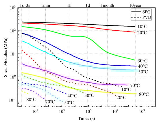
Figure 1.
Variation Curves of Shear Modulus of SGP and PVB with Respect to Time and Temperature.
3. Structure
3.1. Number of Glass Layers
Current specifications at home and abroad do not impose mandatory requirements on the number of layers of laminated glass. GB 15763.3-2009 [18], ISO 12543-2:2021 [25], and EN 14449:2022 [26] all mention that increasing the number of glass layers can effectively improve the impact resistance of laminated glass, and the specific number of layers should be determined through shot bag impact tests. Wang et al. [35] studied the low-velocity impact mechanical behavior of SGP-laminated glass and found that increasing the number of layers increased the impact energy required for subsequent fracture, but the fracture energy decreased. Central four-point bending tests on the static load strength of double-layer and three-layer SGP-laminated glass after impact-induced damage were carried out by Liu Xinwei et al. [36] The results showed that the strength of three-layer laminated glass after cracking could reach more than three times that of double-layer laminated glass, and three-layer laminated glass could exert the performance of the interlayer layer by layer. Coult et al. [37] pointed out that multi-layer SGP-laminated glass had higher blast resistance than double-layer laminated glass, and increasing the number of layers could maintain structural integrity more effectively. Yun et al. [38] showed that the stiffness and load-bearing capacity of PVB laminated glass increased with the number of layers, but this growth trend would slow down as the number of layers increased; therefore, it was not recommended to increase the number of layers indefinitely. Gupta et al. [39] found through numerical simulation that increasing the number of glass layers could significantly improve the impact resistance of laminated glass under static and dynamic loads.
For laminated glass with any type of interlayer, both the flexural bearing capacity and stiffness of the laminated glass increase with the increase in the number of glass layers. However, this increase is not linear and shows a decreasing trend. In combination with the provisions of GB 15763.3-2009, ISO 12543-2:2021, and EN 14449:2022, it is recommended that the number of layers of vehicle-borne laminated glass be controlled between 3 and 5.
3.2. Thickness of Glass Panels
The thickness of glass panels is directly related to the stiffness and load-bearing capacity of laminated glass; therefore, selecting an appropriate thickness of glass panels is crucial for the design of vehicle-borne glass structures. Numerical simulations were conducted by Gao Xuanneng et al. [40] to calculate the deformation of laminated glass with different thicknesses under long-term, short-term static loads, and explosive impacts. The results showed that the thickness of the inner and outer glass panels was the main factor affecting the overall deformation of laminated glass, and this research method has been widely cited in subsequent studies. Impact tests were conducted on 8 mm and 10 mm tempered laminated glass panels by Biolzi et al. [22], and found that the 10 mm-thick glass had higher load-bearing capacity. Gupta et al. [39] found through numerical simulation that laminated glass with thicker glass panels had higher impact resistance, lower peak displacement, a later time to reach the peak, and less damage. Three-point bending tests were used by Ravimony et al. [41] to compare laminated glass with different thicknesses, and concluded that the initial failure load and stiffness were negatively correlated with thickness, while the residual load and initial failure deflection were positively correlated with thickness. In addition, current specifications at home and abroad do not directly mention the thickness of glass panels, but both the ASTM E1300-16 [20] and JGJ 102-2003 [17] refer to the relationship between the thickness of glass panels and the midpoint deflection. Considering the influence of glass nonlinear deformation, ASTM E1300-16 establishes a mathematical relationship between the thickness, aspect ratio, and midpoint deflection of glass panels with four-sided support through polynomial curve fitting:
where is the uniformly distributed load (N/mm2). is the length of the long side (mm); is the length of the short side (mm); is the elastic modulus of the glass panel (N/mm2); is the minimum thickness of the glass panel (mm). The deformations of glass panels with different aspect ratios and thicknesses under a uniformly distributed load of 1 kPa are calculated in accordance with Equations (1)–(5), and the corresponding relationship shown in Figure 2 can be obtained.
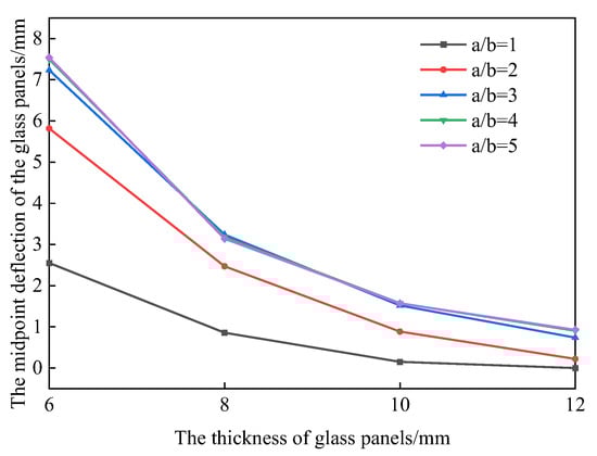
Figure 2.
Relationship Between Glass Thickness and Glass Central Deflection in ASTM E1300-16.
Based on the elastic small-deflection theory and considering a certain correction coefficient, the specification JGJ 102-2003 [17] establishes the relational formula between the thickness of glass panels with four-sided support and the midpoint deflection as follows:
where is the deflection coefficient; is the reduction coefficient; is the length of the short side (mm); is the stiffness of the glass panel(N/mm); is the thickness of the glass panel (mm); is the Poisson’s ratio of the glass panel.
The deformations of glass panels with different aspect ratios and thicknesses under a uniformly distributed load of 1 kPa are calculated in accordance with Equation (6), and the corresponding relationship shown in Figure 3 can be obtained.
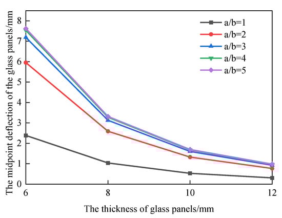
Figure 3.
Relationship Between Glass Thickness and Glass Central Deflection in JGJ 102-2003.
It can be seen from Figure 2 and Figure 3 that the results of the two calculation methods are basically consistent. With the increase in the thickness of glass panels, the midpoint deflection of the glass panels decreases gradually; when the glass thickness exceeds 8 mm, the midpoint deflection tends to stabilize. JGJ 113-2015 [16] stipulates that the thickness of frame-supported floor glass shall not be less than 8 mm. DB 13(J)/T 264-2018 [9] does not provide much description on the thickness of glass panels, but recommends following the requirements in JGJ 113-2015. Therefore, it is suggested in this paper that the thickness of glass panels for vehicle-borne bridge decks shall not be less than 8 mm, and the specific thickness shall be determined based on the deformation, stress, and load-bearing capacity requirements of the actual project.
3.3. Thickness of Interlayers
Numerous studies have shown that increasing interlayer thickness can improve the impact resistance of laminated glass, but it reduces the stiffness of laminated glass and imposes higher requirements on the production process. Through numerical simulation, it was found by Gupta et al. [39] that a thicker interlayer helps reduce the peak displacement of laminated glass and delay its occurrence time, thereby significantly improving impact resistance. It was found by Chen Jun et al. [42] that as interlayer thickness increases, the load-bearing capacity of laminated glass decreases, and the creep effect of the film at high temperatures becomes more significant. Through the comparison of various adhesives by Overend et al. [32], it was found that the average shear strength of the interlayer is inversely proportional to its thickness. It was further confirmed by Machalická et al. [43] that an increase in interlayer thickness reduces its bonding strength, and the interlayer hardness has a significant impact on its bonding strength. International specifications mainly address interlayer thickness in terms of performance correlation. Although EN 14449:2022 [26] does not directly specify interlayer thickness, it imposes restrictions on the shear modulus of interlayers after hygrothermal aging, indirectly avoiding the risk of performance degradation that may be caused by excessively thin interlayers. Domestic specifications, on the other hand, focus more on safety control in application scenarios. Polyvinyl Butyral (PVB) Film for Laminated Glass (JC/T 2166-2013) [44] specifies the thickness of PVB films, and the interlayer thickness is generally an integer multiple of 0.38 mm, establishing a benchmark for standardized production. DB 13(J)/T 264-2018 [9], consistent with JGJ 113-2015 [16], stipulates that the interlayer thickness shall be not less than 0.76 mm and not more than 2.28 mm. This requirement not only addresses the shear strength issue caused by increased interlayer thickness but also balances the process risk of defects easily occurring in production with excessively thin interlayers. Notably, although there are methodological differences between Chinese and foreign specifications regarding the correlation between thickness and performance, the reason lies in the fact that domestic specifications are more conservative in calculating equivalent thickness, which can, to a certain extent, address the stiffness degradation caused by increased interlayer thickness. Therefore, it is recommended in this paper that the interlayer thickness of laminated glass be controlled between 0.76 mm and 2.28 mm to ensure production quality, and at the same time, the performance indicators of EN 14449: 2022 [26] should be referred to for refined design.
3.4. Aspect Ratio
Scholars at home and abroad have conducted extensive research on the aspect ratio of laminated glass panels. It was found by Kamarudin et al. [45] through finite element analysis that the buckling load of laminated glass panels decreases nonlinearly with the increase in aspect ratio; when the aspect ratio is greater than 2.5, the load is mainly borne by the short sides, leading to a decrease in shear transfer efficiency and weakened stability. It was found by Duser et al. [46] that laminated glass with an aspect ratio greater than 2.5 generates significant membrane stress under uniform load, causing the stress development to exceed the “global limit” and “delamination limit”; stress concentration in the short-side direction promotes creep. Based on a finite element model, Zhang [47] studied the influence of the aspect ratio of glass panels on the impact resistance of laminated glass, and found that when the panel area was constant, the failure probability of laminated glass first decreased and then increased with the increase in the aspect ratio, and the impact resistance was optimal when the aspect ratio was approximately 2. Fan [48] studied the behavior of glass panels with the same area but different aspect ratios under the same load, and found that the maximum deflection of the glass panels decreased as the aspect ratio increased. In terms of specifications, ASTM E1300-16 [20] uses a clear aspect ratio to adjust the deflection calculation results by influencing the stiffness coefficient, indirectly guiding the avoidance of excessively large aspect ratios in design. ISO 12543-2:2021 [25] specifies that the aspect ratio of specimens should be 1–2, and requires unidirectional force-bearing verification for glass components with an aspect ratio greater than 2. Based on the above, it is recommended that the aspect ratio of the glass be controlled between 1 and 2 to ensure that the glass panels have good flexural performance and blast resistance.
3.5. Bridge Deck Drainage
Ponding water on bridge decks tends to form a water film on the glass surface, significantly reducing the friction coefficient of the bridge deck panels [49]; moreover, rainwater is prone to seeping into the glass-interlayer interface or support gaps, causing defects such as interlayer debonding and corrosion of support components. Therefore, drainage design is crucial for ensuring the long-term structural safety and driving stability.
With reference to the General Code for Design of Highway Bridges and Culverts (JTG/D 60-2015) [50], it is recommended in this study that a 1.5–2.0% unidirectional or bidirectional transverse slope be set on the bridge deck to accelerate rainwater drainage. Furthermore, the peripheral edges of the glass panels should be fully sealed with neutral silicone sealant; rubber strips or neutral silicone sealant should be embedded in the contact surfaces between the glass and support frames. This not only prevents rainwater from seeping into the support interface but also avoids stress concentration in the glass panels caused by direct contact between the two components. Meanwhile, the support frames should undergo simultaneous waterproof and anti-rust treatment.
In addition, it is recommended that the bridge deck be temporarily closed after rain to prohibit the entry of vehicles and personnel.
4. Structural Calculation
4.1. Design Loads and Load Combinations
In the design of a vehicle-borne glass bridge deck, the load partial factors shall be determined in accordance with the Unified Standard for Reliability Design of Building Structures (GB 50068-2018) [51], the Unified Standard for Reliability Design of Highway Engineering Structures (JTG 2120-2020) [52], and Eurocode 1—Actions on structures—Part 2: Traffic loads on bridges and other civil engineering works (EN 1991-2:2023) [53]. The load values shall be referred to General Specifications for Design of Highway Bridges and Culverts (JTG/D 60-2015) [50], Unified Standard for Loads on Building Structures (GB 50009-2012) [54], and Bridge Design Specifications, 9th Edition, Includes Errata (AASHTO-LRFD) [55], and the loads shall be selected based on the structural components.
4.1.1. Design Loads
The loads acting on the bridge deck shall include: (1) Permanent actions: self-weight of laminated glass, etc.; (2) Variable loads: vehicle loads, vehicle impact forces, vehicle braking forces, crowd loads, wind loads, snow loads, etc.; (3) Accidental actions: falling rocks, glass panel breakage, etc.
The self-weight of laminated glass shall be based on the actual design. When relevant design parameters are not available, the value can be taken as 25.6 kN/m3 in accordance with relevant specifications [17].
According to DB 13(J)/T 264-2018 [9], the value of crowd load is 3.5 kN/m2, while the value of crowd load in JTG/D 60-2015 is 3.0 kN/m2 [50]; EN 1991-2:2023 specifies that a local concentrated load of 0.5 kN should be superimposed on the basic load of 2.5 kN/m2 [53]. For safety considerations, 3.5 kN/m2 is adopted as the standard crowd load in this study. At present, the vehicle-borne glass bridge deck is only used for small cars and pedestrians. Through investigation, the total weight of mainstream small cars is generally about 2000 kg; therefore, the wheel load is taken as 5 kN [56]. According to JTG/D 60-2015 and AASHTO-LRFD [55], when calculating structural members, an impact coefficient of 0.3 should be superimposed on the vehicle load, and the vehicle braking force should be calculated as 10% of the total vehicle weight; the vehicle impact force is not considered under the serviceability limit state. The consideration of vehicle impact is similar to that in JTG, but the impact partial factor is set separately. The calculation of wind load can be carried out in accordance with Specification for Wind—Resistant Design of Highway Bridges (JTG/T 3360-01-2018) [57]. Meanwhile, DB 13(J)/T 264-2018 recommends that the basic wind speed value should be taken based on a 50-year return period; Eurocode 1: Actions on structures—Part 1-4: General actions—Wind actions (EN 1991-1-4) [58] supplements the gust coefficient and clarifies that the basic wind speed should be converted using the 10 min average wind speed, which is basically consistent with the wind speed observation data at a height of 10 m in China. The snow load shall be calculated in accordance with Load Code for the Design of Building Structures (GB 50009-2012) [54].
where is the standard value of snow load (kN/m2); is the snow distribution coefficient on the roof area; is the basic wind pressure (kN/m2).
Considering that some bridge decks may be at risk of falling rocks sliding down, during the design process, the potential impact of rockfall on bridge safety shall be evaluated according to specific environmental conditions, and corresponding structural strengthening measures shall be taken based on this evaluation.
4.1.2. Load Combination
For the design of the ultimate limit state of bearing capacity of vehicle-borne glass bridge decks, the basic combination or accidental combination of loads shall be used for calculation; for the design of the serviceability limit state, the frequent combination or quasi-permanent combination of loads shall be used for calculation. Based on this, the determined load combinations are as follows:
Basic combination:
Accidental combination:
Frequent combination:
where is the structural dead load; is the vehicle load excluding impact force; is the vehicle load including impact force; is the vehicle braking force; is the crowd load; is the wind load; is the snow load.
Provisions on seismic action are specified in both domestic and international specifications. Although the glass bridge deck cannot be completely regarded as rigid panels, when they are designed as structural components, seismic action basically does not play a controlling role; therefore, seismic action is temporarily not considered in the design of the vehicle-borne glass bridge deck.
4.2. Calculation Model
For conventional calculations in this study, a single laminated glass panel is used as the calculation model for the bridge deck, as shown in Figure 4. The performance parameters of the glass and interlayer materials shall comply with the structure described in Section 2.
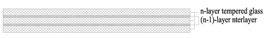
Figure 4.
Calculation Model of Vehicle-Borne Glass Bridge Deck.
It should be noted that although the self-explosion risk of tempered glass can be significantly reduced through heat soaking treatment, there is still a risk of breakage in actual service. Therefore, the adverse working condition of single-layer glass breakage shall be incorporated into the calculation model. At this point, the stress and deflection of the glass panel shall meet the design requirements under short-term load action, to ensure that the glass does not completely lose its load-bearing capacity after breakage. After glass breakage, it can be determined that the broken glass and its adjacent interlayer film lose their load-bearing capacity; the effective force-bearing part is shown in Figure 5 and Figure 6.
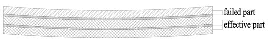
Figure 5.
Working Condition of Surface Layer Glass Breakage.
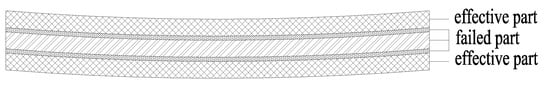
Figure 6.
Working Condition of Middle Layer Glass Breakage.
4.3. Design Criteria
On the basis of comprehensively considering JTG/D 60-2015, DB 13(J)/T 264-2018, Technical Code for Urban Pedestrian Overpasses and Subways (CJJ 69-95) [59], and research results of experts in the field, and combining with the actual application scenarios of vehicle-borne glass bridge decks, the following design criteria are proposed:
(1) Principle of bearing capacity calculation: The flexural strength limit of glass shall adopt the design value of glass strength under long-term load [34].
(2) Principle of deformation check: The deflection value of the glass bridge deck shall not be greater than 1/200 of its short-span [9].
(3) Principle of stress calculation for single-layer glass in laminated glass: The maximum stress value of single-layer glass in laminated glass can be calculated by using the thin-plate large-deflection and small-deflection theories [16].
(4) Principle of deflection and stiffness calculation for laminated glass: The maximum deflection of laminated glass shall be calculated according to the equivalent single glass, and the stiffness of laminated glass shall be calculated according to the equivalent thickness.
4.4. Calculation Methods
4.4.1. Equivalent Thickness
In the calculation of deflection and strength of laminated glass, the concept of equivalent thickness of laminated glass is introduced to facilitate design. That is, it is assumed that some mechanical behaviors of laminated glass are equivalent to those of a single-layer glass panel with the same length and width but a thickness equal to the equivalent thickness. Theoretical derivations on the calculation method of the equivalent thickness of laminated glass have been conducted by domestic and international specifications, experts, and scholars, but most studies have focused on double-layer laminated glass. The following is a summary of the calculation methods for the equivalent thickness of laminated glass.
The standards Large yachts—Strength, weathertightness and watertightness of glazed openings (BS ISO 11336-1-2023) [60] and Standard Practice for Determining Load Resistance of Glass in Buildings (ASTM E1300-12a) [61] specify the calculation methods for the equivalent thickness for deflection and strength, respectively, and the shear transfer effect of the interlayer is taken into account:
The equivalent thickness for deflection is:
The equivalent thickness for strength is:
where is the thickness of the first layer of the glass panel, in mm; is the thickness of the second layer of the glass panel, in mm; is the thickness of the interlayer, in mm; is the thickness of the laminated glass, in mm; and are distribution coefficients, in mm; is a coefficient, in mm3; is the shear transfer coefficient; is the length of the short side of the four-sided simply supported glass panel, in mm; is the shear modulus considering creep factors under gravity. When PVB material is used, can be regarded as 0; when SGP material is used, shall be determined according to the design parameters provided by the manufacturer.
In JGJ 102-2003, the equivalent thickness of laminated glass is simplified as the effect of the simple superposition of double-layer glass. This calculation result tends to be conservative when SGP material is used as the interlayer:
The above calculation methods for the equivalent thickness of laminated glass are only applicable to double-layer glass, and there are currently few calculation methods for laminated glass with more than two layers.
Huang [62] et al. derived the calculation methods for the equivalent thickness of deflection and strength applicable to multi-layer laminated glass, based on the calculation method for multi-layer composite beams considering interlayer slip [63]:
The equivalent thickness for deflection is:
The equivalent thickness for strength is:
where is the equivalent moment of inertia of laminated glass for out-of-plane bending; is the equivalent section modulus of laminated glass for out-of-plane bending; is the length of the short side of the laminated glass panel.
The calculation method for equivalent thickness adopted in the specification DB13(J)/T 264-2018 refers to that in JGJ 102-2003. It simplifies laminated glass as the effect of direct superposition of multi-layer glass, which is equivalent to an extension of the calculation method in JGJ 102-2003, and also does not consider the influence of the interlayer on laminated glass:
where ,, are the thicknesses of each single glass panel, respectively; is the number of layers of the laminated glass.
In conclusion, it is recommended to use the method specified in BS ISO 11336-1-2023 for the calculation of equivalent thickness. When PVB material is used as the interlayer, its shear transfer effect can be neglected; therefore, the calculation results of the above two calculation methods are consistent. When SGP material is used as the interlayer, its shear transfer modulus is relatively large, and the calculation using the specification BS ISO 11336-1-2023 is more in line with the actual situation.
4.4.2. Deflection and Strength Calculation
At present, the calculation methods for the deflection and strength of laminated glass are relatively unified, all of which are formulas derived based on the thin-plate small-deflection bending theory. The stress in the glass panel is calculated as follows:
where is the maximum stress of the i-th glass panel; is the design value of the load combination acting on the i-th glass panel; a is the length of the short side of the glass panel; is the thickness of the glass panel; m is the bending moment coefficient, which can be obtained by consulting relevant specifications.
The mid-span deflection of the glass panel is calculated as follows:
where is the design value of the load combination acting on the glass; is the length of the short side of the glass panel; is the deflection coefficient, which can be obtained by consulting relevant specifications; is the stiffness of the glass.
The above calculation formulas are widely used in the design of glass curtain walls and pedestrian glass bridge decks. However, these formulas are mainly applicable to the case of uniformly distributed full-area loads and are not suitable for the calculation of wheel pressure, a type of concentrated load. Cheng [14] et al. and Li [15] et al., respectively, used the thin-plate large-deflection theory and thin-plate small-deflection theory, established analytical equations based on the Nevier method, and derived calculation formulas for the stress and deflection of glass bridge decks under local loads.
The calculation methods for deflection and stress derived based on the thin-plate large-deflection theory are as follows:
The calculation methods for deflection and stress derived based on the thin-plate small-deflection theory are as follows:
Cheng [14] et al. verified the calculation formulas for the deflection and stress of laminated glass panels through comparative tests and theoretical calculations. The results showed that when a 19th-order series was adopted, the calculation results of the theoretical values were basically stable, and the load-deflection curve calculated by the large-deflection theory was in good agreement with the test data.
5. Example Calculation
The glass bridge deck structure of a steel-framed glass passage bridge project in an auto parts center is taken as an example. This bridge deck has a single span length of 11.7 m, a total length of 117 m, and a bridge width of 6.15 m. As shown in Figure 7, each span of the bridge deck is composed of 6 × 9 glass panels, with the dimensions of each glass panel being 1025 × 1300 mm. The aspect ratio is approximately 1.27, which falls within the range of 1 to 2 as recommended in the previous section, ensuring the glass panels possess good flexural performance and blast resistance.
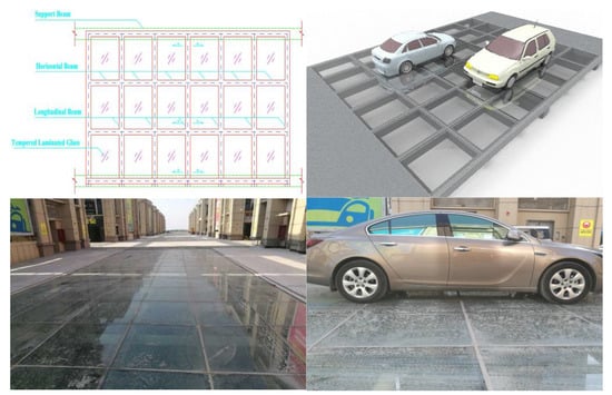
Figure 7.
Engineering Example.
The structure of the glass panel is tempered laminated glass with (15 mm glass × 3 + 1.52 mm interlayer × 2). This structure meets the requirement proposed earlier that the number of glass layers should be controlled between 3 and 5, and the thickness of a single-layer glass panel should not be less than 8 mm. Meanwhile, the interlayer thickness of 1.56 mm is greater than the recommended 0.76 mm, which ensures the structural reliability. The elastic modulus of the glass is 88 GPa, and the Poisson’s ratio is 0.2.
According to the service conditions, the vehicle wheel load is a local uniformly distributed load of 5.0 kN, with the wheel load area being 100 × 200 mm. The crowd load is 3.5 kN/m2, the wind load is 0.32 kN/m2, and the snow load is 0.2 kN/m2. Among these loads, the self-weight and crowd load act on the entire surface of the glass panel, while the wheel load is a local, uniformly distributed load. Therefore, a “load effect superposition” calculation method is adopted: the stress and deflection values calculated by treating the self-weight and crowd load as fully distributed, uniformly distributed loads are superposed with the stress and deflection values calculated by treating the wheel load as a local uniformly distributed load, so as to obtain the total stress and deflection values of the glass panel.
5.1. Load Calculation
Basic combination of uniformly distributed loads:
Basic combination of wheel loads:
The calculated values of other load combinations are shown in Table 2:
Table 2.
Calculated Values of Load Combinations.
For this calculation example, which is located in an urban area with no high-rise buildings in the vicinity, the effect of falling rocks is not considered temporarily; under accidental conditions, only the condition of single glass panel breakage is considered.
5.2. Calculation of Stress and Deflection
Table 3 shows the calculation results of stress and deflection of PVB laminated glass under different load combinations.
Table 3.
Calculation Results of PVB-Laminated Glass.
Table 4 shows the calculation results of stress and deflection of SGP laminated glass under different load combinations.
Table 4.
Calculation Results of SGP-Laminated Glass.
It can be seen from the above calculation results that under the conventional most unfavorable load condition, the calculated value of the central stress of PVB laminated glass is 34.93 MPa, which is close to the stress limit of tempered glass under long-term load, with a small safety margin. In contrast, the calculated value of the central stress of SGP-laminated glass is only 7.46 MPa, which is much lower than the same limit, with a larger safety redundancy. Therefore, SGP material is more recommended for vehicle-borne glass bridge decks. Under the adverse working condition of middle-layer glass breakage, since neither of the two interlayer materials is included in the mechanical contribution, their calculated stress and deflection values are consistent; both are much lower than the stress limit of tempered glass under short-term load, which still meets the safety design requirements.
5.3. Finite Element Calculation and Analysis
The finite element model of laminated glass is shown in Figure 8, including tempered glass, interlayers, rubber tires, and rubber supports; among which the specifications of glass panels and interlayer are consistent with those in the calculation example. Glass, interlayer, tires, and rubber supports all use C3D8H solid elements.
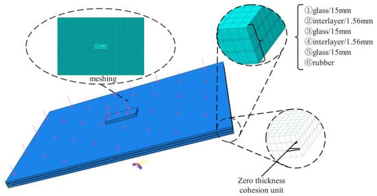
Figure 8.
Finite Element Model of Laminated Glass Bridge Deck.
Glass is treated as a linear elastic body, while interlayers, tires, and rubber supports all adopt the Mooney–Rivlin constitutive model. To simulate the adhesion between glass and interlayers, a zero-thickness cohesive element (COH3D8) is inserted between them, and the bilinear intrinsic cohesive material model is adopted—with parameters such as the strength and fracture energy of glass material as the main variables. The material parameters are shown in Table 5.
Table 5.
Material Parameters.
The contour diagrams of stress and deflection of PVB and SGP laminated glass bridge decks under different load combinations are shown in Figure 9 and Figure 10.
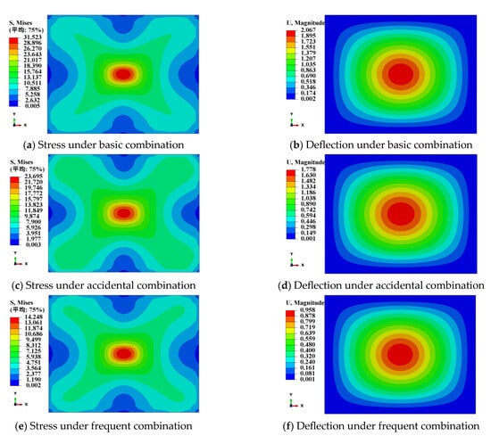
Figure 9.
Finite Element Simulation Results of PVB Laminated Glass.
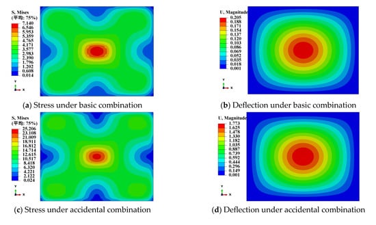
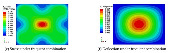
Figure 10.
Finite Element Simulation Results of SGP-Laminated Glass.
The comparison between the finite element simulation results and the design method calculation results of vehicle-borne glass bridge decks is shown in Table 6 and Table 7. It can be seen from the comparison results that the calculation results of the design method for both types of laminated glass are slightly more conservative than the finite element results. Secondly, the design method is more accurate in calculating the stress and deflection of SGP-laminated glass. The difference may be due to the neglect of the shear transfer effect of PVB material in the calculation of the PVB laminated glass design method, which makes its calculation results more conservative.
Table 6.
Comparison Between Finite Element Simulation and Design Method Results for PVB Laminated Glass.
Table 7.
Comparison Between Finite Element Simulation and Design Method Results for SGP-Laminated Glass.
6. Conclusions
By combining domestic and international specifications as well as relevant research, this study proposed a systematic design method suitable for vehicle-borne glass bridge decks, and verified the calculation of the engineering example through finite element analysis. The following conclusions can be drawn:
(1) This study revealed the adaptability mechanism of laminated glass materials under vehicle-borne scenarios. Tempered glass subjected to homogenization treatment should be preferred for bridge deck glass, and it should comply with the requirements of relevant specifications. SGP interlayer material exhibits better durability, heat resistance, and mechanical properties, so it is recommended as the priority choice for laminated glass.
(2) This study clarified the structural design of vehicle-borne glass bridge decks. The number of layers of laminated glass should be controlled within 3–5, the thickness of single-layer glass should not be less than 8 mm, and the aspect ratio should be controlled within 1–2 to balance flexural performance and blast resistance; the interlayer thickness should be set between 0.76 and 2.28 mm.
(3) Based on relevant domestic and international specifications, this study proposed the design loads, load combination methods, calculation models, design criteria, and equivalent thickness calculation method suitable for vehicle-borne glass bridge decks. Meanwhile, the adverse working condition of single-layer glass breakage was incorporated into the design considerations to ensure that the glass still retains sufficient load-bearing capacity after breakage.
(4) This study calculated the engineering example based on the thin-plate large-deflection calculation theory, and the calculation results showed good agreement with the numerical simulation results. The results indicate that both PVB and SGP-laminated glass can meet the load-bearing capacity requirements, but SGP-laminated glass has a larger safety redundancy; after single-layer glass breakage, the bridge deck still has sufficient load-bearing capacity. The calculation results of the design method are slightly more conservative than those of the finite element calculation, but the method is more accurate in calculating the stress and deflection of SGP-laminated glass.
The long-term performance of laminated glass has a direct impact on the full-life-cycle performance of vehicle-borne glass bridge decks. However, due to the limitations of the length of this study, an in-depth discussion on this aspect was not conducted. Future studies will further deepen this research direction to improve the proposed design method.
Author Contributions
Conceptualization, B.Z. and G.C.; methodology, B.Z., J.X. and G.C.; software, J.X. and G.C.; validation, J.S.; formal analysis, B.Z. and J.X.; investigation, G.C. and J.S.; resources, B.Z. and G.C.; data curation, J.X.; writing—original draft preparation, B.Z. and J.X.; writing—review and editing, G.C. and J.S.; visualization, J.X.; supervision, B.Z. and G.C.; project administration, B.Z. and G.C.; funding acquisition, G.C. All authors have read and agreed to the published version of the manuscript.
Funding
This research was funded by the Natural Science Foundation of Shaanxi Province (Grant No. 2018JQ5219) and the Shaanxi Qinchuangyuan “Scientist + Engineer” Team Construction Project (Grant No. 2022KXJ-036).
Data Availability Statement
Data are contained within the article.
Conflicts of Interest
Author Baojun Zhao was a part-time doctoral student at the School of Highway, Chang’an University, and was also employed by Shaanxi Transportation Holding Group Co., Ltd. Author Jiang Xing was a doctoral student at the School of Highway, Chang’an University. Author Gao Cheng was a doctoral supervisor at the School of Highway, Chang’an University, and was also employed by The Engineering Design Academy of Chang’an University Co., Ltd. Author Jufeng Su was employed by The Engineering Design Academy of Chang’an University Co., Ltd. The remaining authors declare that the research was conducted in the absence of any commercial or financial relationships that could be construed as a potential conflict of interest.
References
- Ma, J.R.; Luo, Y.; Liu, Z.W. Application Technology of Architectural Glass; Chemical Industry Press: Beijing, China, 2005; ISBN 978-7-5025-6117-8. [Google Scholar]
- Hänig, J.; Weller, B. Load-Bearing Behaviour of Innovative Lightweight Glass–Plastic-Composite Panels. Glass Struct. Eng. 2020, 5, 83–97. [Google Scholar] [CrossRef]
- Zhang, T.H. Research on the Shear Load-bearing Performance of Glass Panel Elastically Supported on Two Opposite Sides. Master’s Dissertation, China Academy of Building Research, Beijing, China, 2022. [Google Scholar]
- Adam, R.; Milan, S. Vibration Serviceability Limit State of Pedestrian Bridges. Građev. Mater. Konstr. 2021, 64, 177–183. [Google Scholar] [CrossRef]
- Xia, Q.; Xiang, P.; Peng, L.; Wang, H.; Jiang, L. Interlayer Shearing and Bending Performances of Ballastless Track Plates Based on High-Order Shear Deformation Theory (HSDT) for Laminated Structures. Mech. Adv. Mater. Struct. 2024, 31, 1563–1587. [Google Scholar] [CrossRef]
- Siwowski, T.; Kulpa, M.; Rajchel, M.; Poneta, P. Design, Manufacturing and Structural Testing of All-Composite FRP Bridge Girder. Compos. Struct. 2018, 206, 814–827. [Google Scholar] [CrossRef]
- Liu, Q.; Huang, X.K.; Han, W.T.; Cui, M.J.; Fu, R.J. Study on the flexural performance of laminated glass beams. Build. Sci. 2018, 34, 44–49. [Google Scholar] [CrossRef]
- Bedon, C. Diagnostic Analysis and Dynamic Identification of a Glass Suspension Footbridge via On-Site Vibration Experiments and FE Numerical Modelling. Compos. Struct. 2019, 216, 366–378. [Google Scholar] [CrossRef]
- DB13 (J)/T 264-2018; Technical Standard for Pedestrian Glass Suspension Bridge and Glass Trestle in Scenic Spot. China Building Materials Industry Press: Beijing, China, 2018.
- Chen, Y.; He, K.; Chen, C. Research on ultimate bearing capacity of laminated tempered glass panel under local load. China Civ. Eng. J. 2021, 54, 68–78. [Google Scholar] [CrossRef]
- Tang, P. Experimental study on bearing capacity of glass bridge deck under different boundary conditions. J. Nanyang Inst. Technol. 2024, 16, 79–83. [Google Scholar] [CrossRef]
- Tang, P.; Gong, S.; Liang, P.; Cheng, G.; Su, J.F. Experimental study on bearing capacity of glass bridge deck under different boundary conditions. J. Shenzhen Univ. Sci. Eng. 2020, 37, 84–90. [Google Scholar] [CrossRef]
- Peng, T.; Sai, G. Research on the Bending Mechanical Properties of Laminated Glass Panels under Concentrated Loads. Eng. Rep. 2025, 7, e70118. [Google Scholar] [CrossRef]
- Cheng, G.; Wen, B.H.; Tang, P.; Su, J.F. Bending performance of four-side simply supported glass bridge deck under local wheel pressure. J. Shandong Univ. (Eng. Sci.) 2022, 52, 157–165. [Google Scholar]
- Li, T.T.; Hu, M.; Wen, B.H.; Jia, H.Y. Theoretical Solution to Bending Problem of Glass Bridge Deck under Wheel Load. Highway 2022, 67(09), 171–175. [Google Scholar]
- JGJ 113-2015; Technical Specification for Application of Architectural Glass. China Architecture & Building Press: Beijing, China, 2015.
- JGJ 102-2003; Technical Code for Glass Curtain Wall Engineering. China Architecture & Building Press: Beijing, China, 2003.
- GB 15763.3-2009; Safety Glazing Materials in Building—Part 3: Laminated Glass. Beijing Standards Press: Beijing, China, 2009.
- EN ISO 12543-1:2021; Glass in Building—Laminated Glass and Laminated Safety Glass—Part 1: Vocabulary and Description of Component Parts. International Organization for Standardization: Geneva, Switzerland, 2021.
- ASTM E1300-16; Standard Practice for Determining Load Resistance of Glass in Buildings. ASTM International: West Conshohocken, PA, USA, 2016.
- Centelles, X.; Castro, J.R.; Pelayo, F.; Aenlle-López, M.; Cabeza, L.F. Experimental Study and Comparison of Different Fully Transparent Laminated Glass Beam Designs. Glass Struct. Eng. 2021, 6, 463–486. [Google Scholar] [CrossRef]
- Biolzi, L.; Bonati, A.; Cattaneo, S. Laminated Glass Cantilevered Plates under Static and Impact Loading. Adv. Civ. Eng. 2018, 2018, 7874618. [Google Scholar] [CrossRef]
- Zhang, X.; Bedon, C. Vulnerability and Protection of Glass Windows and Facades under Blast: Experiments, Methods and Current Trends. Int. J. Struct. Glass Adv. Mater. Res. 2017, 1, 10–23. [Google Scholar] [CrossRef]
- GB 15763.2-2005; Safety glazing materials in building—Part 2:Tempered glass. China Standards Press: Beijing, China, 2005.
- EN ISO 12543-2:2021; Glass in Building—Laminated Glass and Laminated Safety Glass—Part 2: Performance Requirements and Test Methods. International Organization for Standardization: Geneva, Switzerland, 2021.
- EN 14449:2022; Glass in Building—Laminated Glass with Ionomer Interlayers. European Committee for Standardization: Brussels, Belgium, 2022.
- Król, P.; Król, B. Structures, Properties and Applications of the Polyurethane Ionomers. J. Mater. Sci. 2020, 55, 73–87. [Google Scholar] [CrossRef]
- Cavicchi, K.A.; Pantoja, M.; Cakmak, M. Shape Memory Ionomers. J. Polym. Sci. Part B Polym. Phys. 2016, 54, 1389–1396. [Google Scholar] [CrossRef]
- Yao, Y.; Xiao, M.; Liu, W.G. A Short Review on Self-Healing Thermoplastic Polyurethanes. Macromol. Chem. Phys. 2021, 222, 2100002. [Google Scholar] [CrossRef]
- Yu, L.J. Preparation of High Sound Insulation PVB Composite Film and Its Application on Laminated Glass. Ph.D. Dissertation, Changchun University of Technology, Changchun, China, 2024. [Google Scholar]
- Shim, G.I.; Kim, S.H.; Ahn, D.L.; Park, J.K.; Jin, J.H.; Chung, D.K.; Choi, S.Y. Experimental and Numerical Evaluation of Transparent Bulletproof Material for Enhanced Impact-Energy Absorption Using Strengthened-Glass/Polymer Composite. Compos. Part B 2016, 97, 150–161. [Google Scholar] [CrossRef]
- Overend, M. Glass in Facades and Other Applications. In Structural Design of Buildings; Fu, F., Richardson, D., Eds.; Emerald Publishing: Leeds, UK, 2024; pp. 177–212. ISBN 978-1-83549-573-5. [Google Scholar]
- Na, Z.Y.; Liu, Q.; Han, W.T.; Huang, X.K. Experimental Study on the Bending Performance of Laminated Glass Using Different Interlayers Under Different Temperature Conditions. Build. Sci. 2023, 39, 28–37. [Google Scholar] [CrossRef]
- Liu, J.J.; Cui, Z.Q.; Li, J.H.; Li, T.; Liang, Y.D.; Li, D. Design Method for the Glass Deck of Landscape Bridge. Build. Sci. 2020, 36, 1–6. [Google Scholar] [CrossRef]
- Wang, X.; Yang, J.; Liu, Q.; Zhao, C. Experimental Investigations into SGP Laminated Glass under Low Velocity Impact. Int. J. Impact Eng. 2018, 122, 91–108. [Google Scholar] [CrossRef]
- Liu, X.W.; Yang, J.; Wang, X.E.; Liu, Q. Post-Breakage Strength of Laminated Glass Panel Cracked by Impact. J. Shanghai Jiao Tong Univ. 2020, 54, 227–238. [Google Scholar] [CrossRef]
- Coult, G.; Overend, M. Developments in Structural Glass. Struct. Eng. 2022, 100, 22–24. [Google Scholar] [CrossRef]
- Yun, L.; Li, H.; Zhang, N.; Shi, W.; Haider, R. Research on Out-of-Plane Bending Test of PVB Laminated Glass Plate with Different Number of Layers. Appl. Sci. 2024, 14, 3416. [Google Scholar] [CrossRef]
- Gupta, A.K.; Lin, Y.; Pesek, S.; McDougal, N.; Kent, R.; Dietsche, L. Predictive Analysis of Laminated Glass Performance under Static and Dynamic Loading Conditions. Challenging Glass Conf. Proc. 2024, 9, 1–26. [Google Scholar] [CrossRef]
- Gao, X.N.; Wang, S.P. Deflection of Architectural Laminated Glass Under Static and Explosive Loads. J. Chin. Ceram. Soc. 2008, 36, 1477–1483. [Google Scholar]
- Ravimony, R.; Joseph, A.; Mangal, L. Investigations on the Flexural Performance of Laminated Glass. IOP Conf. Ser. Earth Environ. Sci. 2020, 491, 12023. [Google Scholar] [CrossRef]
- Chen, J.; Zhang, Q.L.; Xie, B.Y.; Tao, Z.X. xperimental Study on Bearing Capacity Performance of Four-Edge Simply Supported Laminated Glass. Struct. Eng. 2011, 27, 115–120. [Google Scholar]
- Machalická, K.; Eliášová, M. Adhesive Joints in Glass Structures: Effects of Various Materials in the Connection, Thickness of the Adhesive Layer, and Ageing. Int. J. Adhes. Adhes. 2017, 72, 10–22. [Google Scholar] [CrossRef]
- JC/T 2166—2013; Polyvinyl Butyral (PVB) Film for Laminated Glass. China Building Materials Industry Press: Beijing, China, 2013.
- Kamarudin, M.K.; Mohd Rais, N.H.; Yusoff, M.M.; Parke, G.A.R. Buckling Behaviour of Laminated Glass Panel in Compression. MATEC Web Conf. 2019, 258, 5010. [Google Scholar] [CrossRef]
- Duser, A.V.; Jagota, A.; Bennison, S.J. Analysis of Glass/Polyvinyl Butyral Laminates Subjected to Uniform Pressure. J. Eng. Mech. 1999, 125, 435–442. [Google Scholar] [CrossRef]
- Zhang, Y.; Li, S.K.; Guo, F.; Lei, J.Y.; Peng, X.; Sun, H.X.; Liu, M. Experimental Study on Flexural Capacity and Finite Element Analysis of Laminated Glass Simply Supported on Four Sides. J. Vib. Shock. 2024, 43, 267–275. [Google Scholar] [CrossRef]
- Fan, C. Theoretical Analysis, Experimental Study and Numerical Simulation of Flexural Properties of Multilayer Composite Glass. Master’s Dissertation, Nanjing University of Aeronautics and Astronautics, Nanjing, China, 2024. [Google Scholar]
- Zheng, B.; Tang, J.; Chen, J.; Zhao, R.; Huang, X. Investigation of Adhesion Properties of Tire—Asphalt Pavement Interface Considering Hydrodynamic Lubrication Action of Water Film on Road Surface. Materials 2022, 15, 4173. [Google Scholar] [CrossRef]
- JTG D60-2015; General Specifications for Design of Highway Bridges and Culverts. China Communications Press Co., Ltd.: Beijing, China, 2015.
- GB 50068-2018; Unified Standard for Reliability Design of Building Structures. China Architecture & Building Press: Beijing, China, 2018.
- JTG 2120—2020; Unified Standard for Reliability Design of Highway Engineering Structures. China Communications Press Co., Ltd.: Beijing, China, 2020.
- EN 1991-2:2023; Eurocode 1-Actions on Structures-Part 2: Traffic Loads on Bridges and Other Civil Engineering Works. European Committee for Standardization: Brussels, Belgium, 2023.
- GB 50009-2012; Load Code for the Design of Building Structures. China Architecture & Building Press: Beijing, China, 2012.
- American Association of State Highway and Transportation Officials. Bridge Design Specifications, 9th ed.; American Association of State Highway and Transportation Officials: Washington, DC, USA, 2020. [Google Scholar]
- Tang, P. Study on Mechanical Properties of Laminated Glass Bridge Panel Under Vehicle Loading. Ph.D. Dissertation, Chang’an University, Xi’an, China, 2023. [Google Scholar]
- JTG/T 3360-01-2018; Specification for Wind-Resistant Design of Highway Bridges. China Communications Press Co., Ltd.: Beijing, China, 2019.
- EN 1991-1-4:2005/A1:2010; Eurocode 1: Actions on structures—Part 1–4: General actions—Wind Actions. European Committee for Standardization European Committee for Standardization: Brussels, Belgium, 2010.
- CJJ69-95; Technical Specification for Urban Pedestrian Overpass and Underpass. China Architecture & Building Press: Beijing, China, 1996.
- BS ISO 11336-1:2023; Large Yachts—Strength, Weathertightness and Watertightness of Glazed Openings. British Standards Institution: London, UK, 2023.
- ASTM E1300-12a; Standard Practice for Determining Load Resistance of Glass in Buildings. ASTM International: West Conshohocken, PA, USA, 2012.
- Huang, X.K.; Cui, M.Z.; Liu, Q.; Nie, J.G.; Zhou, Y.H. Study on Design Method of Multi-layer Laminated Glass Columns Under Axial Compression. J. Build. Struct. 2021, 41, 183–192. [Google Scholar] [CrossRef]
- Zhang, Y.P.; Xu, R.Q. Analysis for Calculating Deflections of Multilayered Composite Beams with Interlayer Slips. Eng. Mech. 2018, 35, 22–26. [Google Scholar]
Disclaimer/Publisher’s Note: The statements, opinions and data contained in all publications are solely those of the individual author(s) and contributor(s) and not of MDPI and/or the editor(s). MDPI and/or the editor(s) disclaim responsibility for any injury to people or property resulting from any ideas, methods, instructions or products referred to in the content. |
© 2025 by the authors. Licensee MDPI, Basel, Switzerland. This article is an open access article distributed under the terms and conditions of the Creative Commons Attribution (CC BY) license (https://creativecommons.org/licenses/by/4.0/).