Abstract
This study investigates the in-plane shear behavior of solid brick masonry walls, both unreinforced and retrofitted using Reinforced Khorasan Jacketing (RHJ), a traditional pozzolanic mortar technique rooted in Iranian and Ottoman architecture. Six one-block-thick English bond masonry walls were tested in three configurations: unreinforced with Horasan plaster (Group I), reinforced with steel mesh aligned to wall edges (Group II), and reinforced with mesh aligned diagonally (Group III). All the walls were plastered with 3.5 cm of Horasan mortar and tested after 18 months using diagonal compression, with load-displacement data recorded. A detailed 3D micro-modeling approach was employed in finite element simulations, with bricks and mortar modeled separately. The Horasan mortar was represented using an elastoplastic Mohr-Coulomb model with a custom softening law (parabolic-to-exponential), calibrated via inverse parameter fitting using the Nelder-Mead algorithm. The numerical predictions closely matched the experimental data. Reinforcement improved the shear strength significantly: Group II showed a 1.8 times increase, and Group III up to 2.7 times. Ductility, measured as post-peak deformation capacity, increased by factors of two (parallel) and three (diagonal). These enhancements transformed the brittle failure mode into a more ductile, energy-absorbing behavior. RHJ is shown to be a compatible, effective retrofit solution for historic masonry structures.
1. Introduction
Masonry structures constitute a major segment of architectural and cultural heritage in many regions of the world. These structures, often characterized by their massive walls, limited tensile capacity, and reliance on gravity-based stability, have been built for centuries using locally available materials and traditional construction techniques. While they exhibit remarkable longevity and architectural richness, their seismic performance is inherently limited due to the absence of ductility and energy dissipation mechanisms. In earthquake-prone regions such as Turkey, this poses a significant threat to the preservation and continued use of such buildings.
In addition to in-plane deficiencies, the out-of-plane behavior of unreinforced masonry (URM) walls poses significant seismic risk. Ehsani et al. [1] demonstrated that FRP retrofitting can enhance the overall seismic performance under simulated earthquake loads. Velazquez-Dimas and Ehsani [2] further highlighted the importance of anchorage detailing in improving out-of-plane stability through numerical modeling. Moreover, shotcrete applications have been proposed as an alternative strengthening method for URM walls, offering substantial structural benefits, though with limited compatibility for heritage contexts [3].
Istanbul, with a history that spans over two millennia, is home to more than 35,000 officially registered historical buildings. However, according to recent estimations, only about 10% of these structures have undergone seismic retrofitting, and a considerable portion remains either unrestored or under partial restoration [4,5]. These figures underscore a critical vulnerability in the built heritage of the city. Most of these buildings were constructed prior to the implementation of seismic codes, and as such, they were primarily designed to resist vertical loads. Their structural systems lack adequate detailing or reinforcement to withstand lateral seismic forces, which often results in brittle and sudden failure during strong ground motion events [6,7,8].
Over time, the original seismic capacity of many masonry structures has been further compromised by a combination of factors, including environmental degradation, water infiltration, foundation settlement, lack of maintenance, inappropriate material substitutions, and functional alterations that disregard the original load paths. In many cases, alterations such as the creation of openings, removal of internal walls, or the addition of new loads have further weakened these structures [9]. Consequently, not only are many historical masonry buildings inherently vulnerable in their original form, but they have also experienced significant structural degradation, making them increasingly susceptible to seismic damage. The preservation of these historical structures, however, must be approached with a dual responsibility: ensuring public safety while maintaining the authenticity and cultural significance of the built fabric [10,11,12]. Contemporary conservation philosophy emphasizes that interventions on historical buildings must be compatible with the original materials and construction systems, reversible where possible, and visually unobtrusive. Interventions that fail to meet these criteria may inadvertently damage the historical integrity of the structure or hinder future restoration efforts. Therefore, the choice of retrofitting strategy becomes critically important in heritage structures, particularly in seismically active zones [13,14].
Conventional retrofitting techniques such as reinforced concrete (RC) jacketing have been widely used in the past for strengthening masonry walls. These methods generally involve increasing the cross-sectional dimensions and applying new, stronger materials over the original masonry surface. However, RC jacketing introduces several drawbacks when used in heritage contexts. These include an increased dead load, poor mechanical compatibility between concrete and masonry, irreversible alterations to the original structure, and potential damage to the historic fabric during the installation process [15,16,17,18]. As a result, RC-based retrofitting has largely been abandoned in favor of more compatible and conservation-oriented solutions.
Recent research has explored alternative techniques that seek to preserve the character and materiality of masonry buildings while enhancing their structural performance. Among these, ferrocement overlays, engineered cementitious composites (ECC), textile-reinforced concrete (TRC), and fiber-reinforced polymer (FRP) systems have received significant attention. Ferrocement retrofitting, in particular, has shown promise due to its thin application, low weight, high tensile strength, and ability to significantly improve the ductility and load-bearing capacity without major intrusion into the existing structure [19,20,21]. Experimental studies conducted by Hasnat et al. [22] and Pérez-Pinedo et al. [23] have validated the effectiveness of ferrocement overlays in both damaged and undamaged walls, including those with openings and lightweight units. Numerical studies by Mukherjee and Kaushik [24] further corroborated that ferrocement retrofitting modifies failure mechanisms, delays collapse, and enhances the global seismic resilience of masonry systems.
Similarly, FRP-based systems particularly those utilizing carbon (CFRP), glass (GFRP), or aramid fibers have been widely applied for strengthening masonry structures. These systems increase the lateral stiffness and peak strength [25,26,27]; however, their application in heritage buildings is limited due to issues such as incompatibility with traditional materials, brittle failure modes, delamination, inadequate anchorage, and challenges with reversibility [28,29,30,31,32,33]. To address these limitations, recent studies have shifted the focus toward more compatible materials such as steel-reinforced grout (SRG), glass fiber grids (GFG), and TRC, which offer improved bond characteristics, better cyclic behavior, and enhanced energy dissipation with more reversible installation methods [34,35,36,37,38]. Despite these advancements, there remains a pressing need for retrofitting solutions that are not only structurally effective but also rooted in traditional construction practices. In this context, lime-based mortars, and specifically Khorasan mortar, offer a promising alternative. Khorasan mortar, a mixture of lime, brick powder (pozzolanic material), and sand, has been historically used in Byzantine and Ottoman architecture due to its durability, compatibility with masonry, and self-healing properties through continued pozzolanic reactions [39]. Its mechanical and chemical compatibility with historical masonry units makes it an ideal candidate for retrofitting applications that require minimal intervention and high fidelity to the original materials [40]. The advantages and disadvantages of the various retrofitting techniques are given in Table 1 below.

Table 1.
Advantages and disadvantages of retrofitting techniques.
This study proposes a novel retrofitting approach that combines steel mesh reinforcement with Khorasan mortar, termed Reinforced Khorasan Jacketing (RKJ), to enhance the seismic resilience of unreinforced masonry (URM) walls. Designed with the compatibility and conservation needs in mind, the method adds tensile capacity and ductility without compromising historical integrity. It was practically implemented during the restoration of the Atik Valide Complex, a 16th-century monument attributed to Mimar Sinan, demonstrating both technical feasibility and cultural suitability. To rigorously evaluate its performance, six one-block-thick English bond masonry walls were tested in diagonal compression after 18 months of aging. Three configurations were studied: unreinforced, reinforced with edge-aligned steel mesh, and reinforced with diagonal mesh, all embedded in 3.5 cm of Khorasan mortar. A 3D finite element micro-model incorporating a Mohr-Coulomb plasticity model with a parabolic-to-exponential softening law was developed and calibrated via inverse fitting using the Nelder-Mead algorithm. The results revealed that RKJ significantly enhances shear strength and ductility—by up to 2.7 and 3 times, respectively—while also shifting the failure mode from brittle to ductile. This paper contributes to the advancement of sustainable, compatible, and structurally effective retrofitting strategies for historic masonry structures in seismic regions.
2. Materials and Methods
The experimental study mainly consisted of two stages: wall assembly and shear test. The materials used in the preparation of the masonry elements, representative of load-bearing masonry walls (length × height × thickness: 120 × 120 × 26 cm) and of the reinforcement, were selected with the intention of compliance with the real cases as much as possible. The masonry specimens were assembled using solid clay bricks with dimensions of 190 mm length, 90 mm height, and 55 mm thickness. In this study, English bond was preferred as the masonry course. All bricks were kept under water to obtain a saturated condition before being used in wall construction. The following Horosan mortar mix design was used for the joints: lime, hydraulic lime (NHL 3.5), natural sand, kufeki stone as sand, brick powder as pozzolan and water, in a volume ratio of 1:0.5:1:1:2:2, respectively. The average particle size of natural sand, kufeki, and brick powder used in both mortar and jacketing mixtures were 1.20 mm, 0.92 mm, and 1.78 mm, respectively. A layer of roughcast was applied, namely lime, hydraulic lime, natural sand, brick powder, and water, in a volume ratio of 1:2:2:2, respectively. Finally, a render layer of a lime mortar having the same composition as the mortar used in the joints was added on both faces of the masonry wall. The thickness of the joints and plaster at each wall was 2 cm and 3 cm, respectively. The compressive strength and modulus of elasticity of the brick and mortar are given in Table 2.
Table 2.
Mechanical test results of brick and mortar.
In order to investigate the effect of steel reinforcement on the shear capacity, three different types of load-bearing masonry walls were built. Type I represents the plain (unreinforced, no-RC) walls as the reference specimens. Type II and Type III walls are constructed according to two different strengthening configurations in terms of mesh opening forms. Type II uses a parallel arrangement of the reinforcement mesh (P-RC), whereas Type III uses a diagonal arrangement (D-RC). The reinforcement was applied on two sides of the wall using 6 mm diameter welded ribbed steel mesh with a cell size of 150 × 150 mm. Steel meshes were placed between roughcast and render layers and connected with Ø8 threaded tie rods with 30 cm intervals both vertically and horizontally. The wall dimensions and reinforcement configurations are described in Figure 1. After strengthening and plaster works, the walls were kept under laboratory ambient conditions at 20 ± 3 °C and 55 ± 10% RH until the testing day (18 months). The reason for a long period of curing time was to provide adequate time for carbonation and strength gain of the lime mortar.
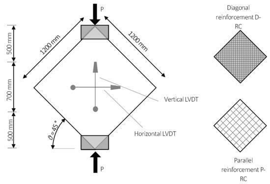
Figure 1.
Experimental setup and RC configurations.
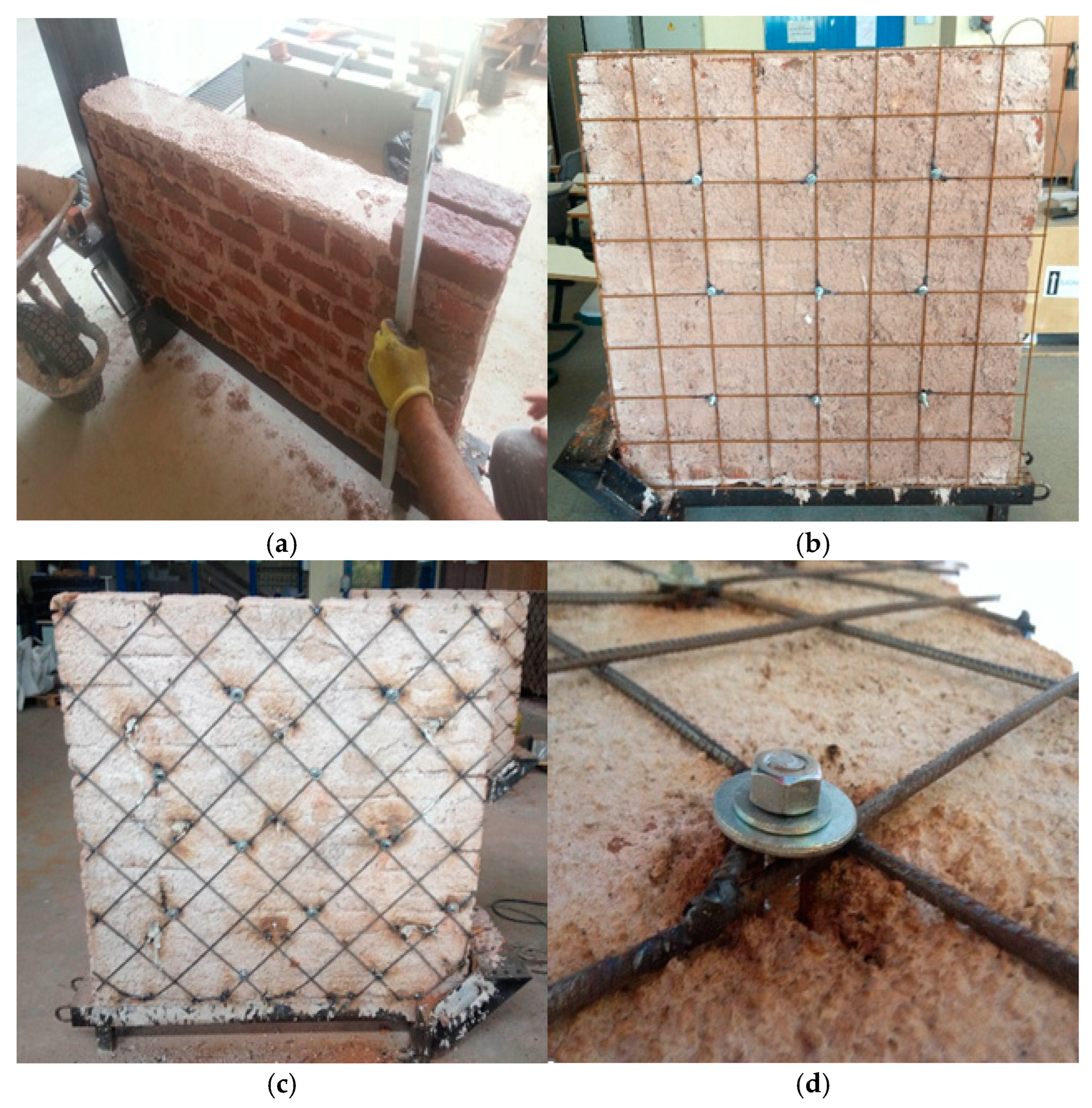
To determine the contribution of the steel mesh reinforcement on the load-carrying capacity (shear strength) and deformation capability before failure, the specimens were loaded along one diagonal (Figure 1) according to ASTM E519. Vertical and horizontal deformations were measured by using 4 linear variable displacement transducers (LVDT’s) placed at the central area of the two sides of the walls (Figure 1). The rate of application of the load was adjusted to 0.5 kN/s. For each category, two walls were tested for the sake of consistency of the experiments. Figure 2 shows the construction stages of the walls as well as the English bond and the application of the parallel and the diagonal reinforcements.
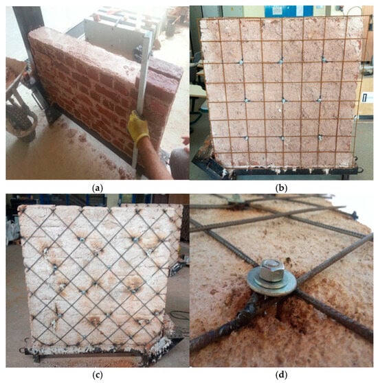
Figure 2.
Masonry work and application of the reinforcement: (a) unreinforced with Horasan plaster; (b) parallel reinforcement PR-C; (c) diagonal reinforcement DR-C; (d) anchoring.
3. Numerical Modeling
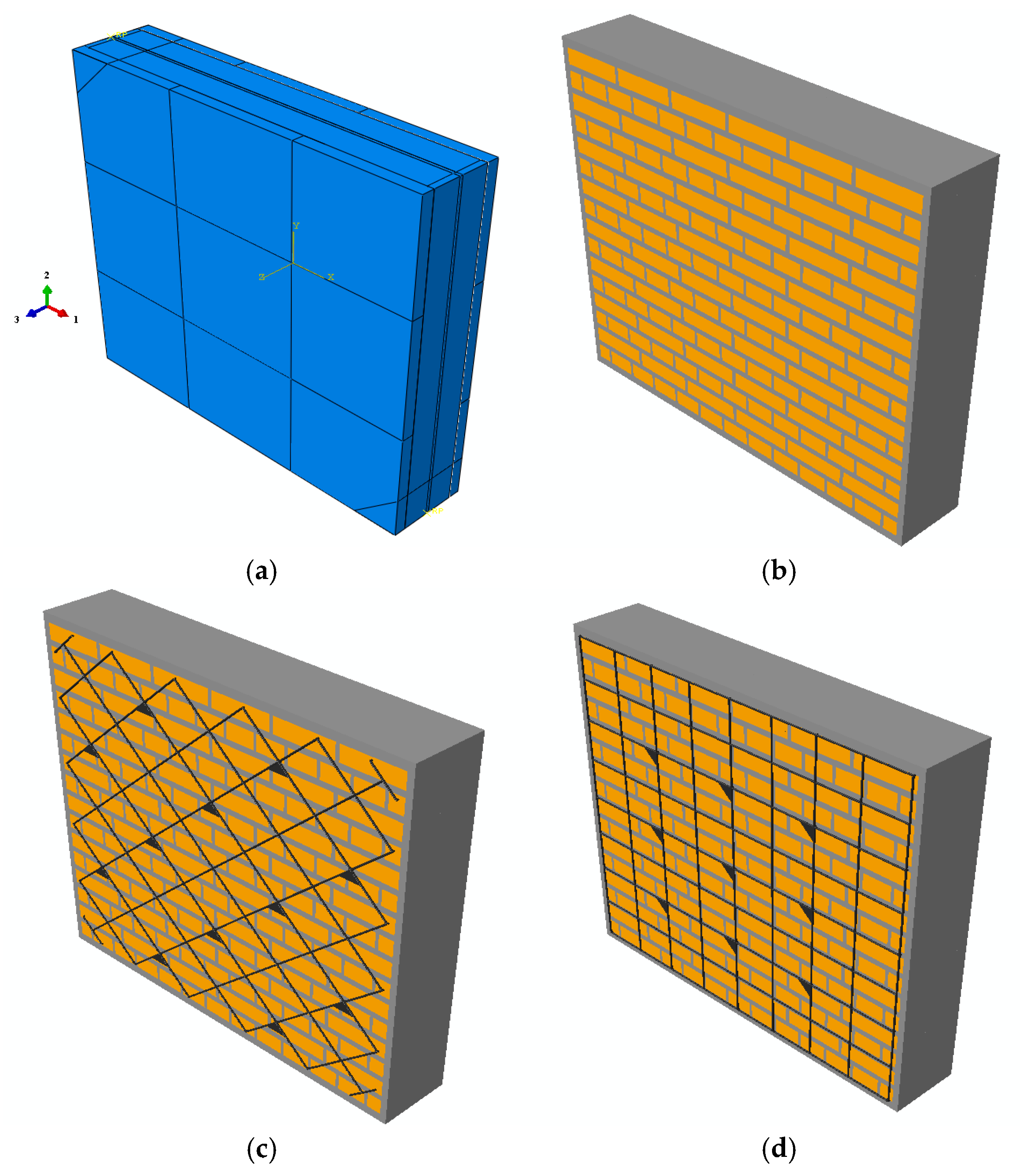
Being a complex structural system itself, there are mainly two approaches for the modeling of masonry walls. These are the macro- and micro-modeling methods. In macro-modeling, homogenized sets of mechanical properties are used irrespective of the detailed composition of the masonry wall. This technique simplifies the analysis and general understanding of the performance of large masonry structures but cannot capture the intricate deformation and inelastic stress concentrations due to the composite nature of the masonry. In the micro-modeling elements of the masonry composition, bricks and the mortar joints are modeled separately in detail. They are taken as different materials with different properties, and even the interface between them can be modeled explicitly. Although it brings a much heavier computational burden with respect to macro-modeling, the micro-modeling of specific experimental studies is required in order to capture the essentials of the mechanical system more realistically. Thus, in this study, we adopted micro-modeling techniques. An algorithm was developed for the digital construction of the brick pattern with the adjusted mortar joints for the ABAQUS 6.14-5c commercial finite element package [51]. A perfect bond was assumed between the mortar joints and the bricks. Reinforcement parts were modeled as embedded elements in the frame of finite element analysis. Explicit finite element analysis was used for the simulations. Figure 3 shows the general model with the plaster applied and when the plaster is removed for the plain (no-RC), parallel reinforcement (P-RC) and diagonal reinforcement (D-RC) cases. The color code clearly shows the perfect assembly pattern of the bricks, mortar joints, and the steel reinforcement produced by the algorithm.
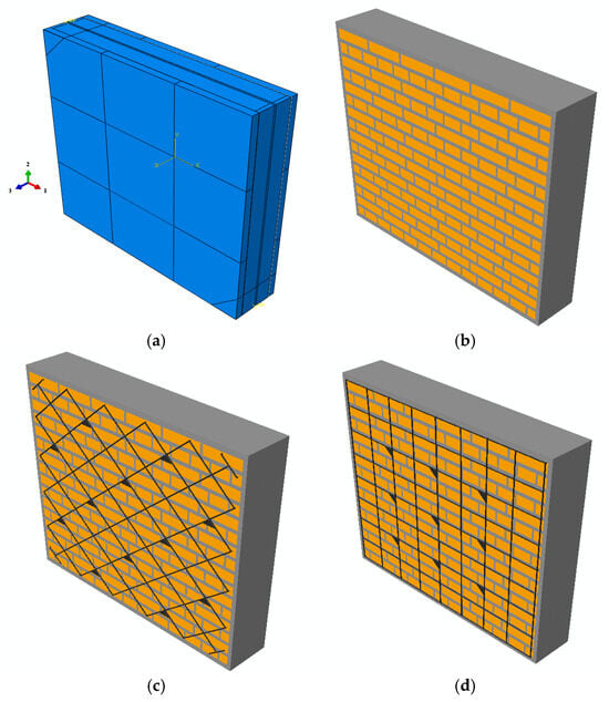
Figure 3.
Numerical model setup and RC configurations: (a) unreinforced with Horasan plaster; (b) parallel reinforcement PR−C; (c) diagonal reinforcement DR−C; (d) anchoring.
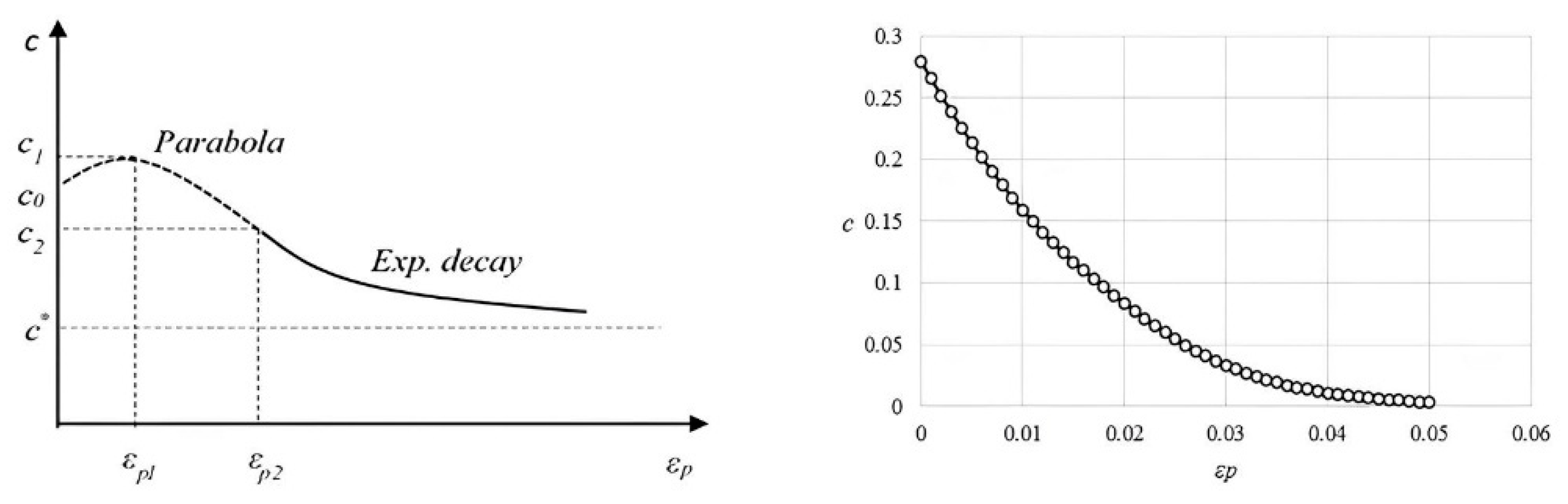
Three-dimensional solid elements were used for the brick-and-mortar joints. Reinforcement was modeled with 1D beam elements. Again, a perfect bond was assumed with the embedded reinforcement elements and the host which is the composition of the 3D bricks and mortar joints. The reinforcement meshes applied to the two sides of the wall were attached to each other with horizontal bars. These bars were threaded and bolted with washers which in turn sat on the small braces constructed at the specific vertices of the mesh during the production of the wall (Figure 2). These corner assemblies were modeled as right triangular shells with a thickness of 4 mm and side length of 40 mm. These shell parts were also embedded and assumed to be in a perfect bond with the bulk of the wall. All the reinforcement parts were modeled as elastic-perfectly plastic steel with a Young’s modulus of 210 GPa and with a yield limit of 500 MPa. For the modeling of the reinforcement parts, classical metal plasticity was used. From the extensive parametric studies, it is understood that the Horasan mortar is the primary contributor to the inelastic characteristic of the wall. It is seen that bricks are acting merely as relatively rigid parts inside a much softer mortar “matrix”. Thus, for the sake of simplicity, bricks are assumed to be linear elastic with a Young’s modulus . The Poisson’s ratio of the bricks is taken to equal that of steel as 0.2, and in fact from analysis, it is found that the results are rather insensitive to Poisson’s ratios, and the same value is also used for the mortar sections as well. For its simplicity, the Mohr-Coulomb plasticity model was selected for the modeling of the mortar plasticity. The primary variables controlling the Mohr-Coulomb model are the Young’s modulus of the mortar , internal friction angle , which controls the effect of normal force on shear capacity, dilatation angle which controls the volume change during plastic deformations, and the well-known cohesion parameter . Defining a single cohesion limit for the initial (zero) plastic strain corresponds to the perfectly plastic case, whereas, in this study, it is intended to capture the softening regime of the behavior as well. Thus, a softening form which is controlled with additional parameters is suggested for the evolution of the cohesion parameter c as a function of the accumulated plastic strain. The suggested form is constructed as a union of a parabola and an exponential decay part. The parabola (1) is controlled with three points on the cohesion-plastic strain plane (, , , with . Thus, for :
The exponential decay part was adjusted such that it effectively started with the point {} and had the same slope (derivative) with the parabola at this point. Thus, for :
Here, is the transition intensity, and since the slopes are the same at , it is found to be:
Finally, the parameter is the ratio with being the asymptotic value of the exponential part. Thus, it is understood that once the parameter set {, , , , , } is defined, the softening behavior is determined for the input to the simulation. This composite form is found to allow the required flexibility of the inverse parameter fitting procedure. Figure 4 shows the representative softening curve for cohesion .

Figure 4.
Representative softening curve and fitted parameter case.
An automated inverse parameter fitting procedure based on the Nelder-Mead method is defined with the experimental Young’s modulus of the mortar from Table 2. Parameters {, , , , , , , } were varied in order to minimize the objective function defined as the square of the normalized L2 norm of the error (e) between the experimental force-displacement readings from LVDT and the model force-displacement results. First a polynomial curve was fitted to experimental force-displacement data () and a continuous function was obtained. Then, for a given set of parameters, discrete force displacements () were calculated from the model and the objective function can be written as:
Iterations led to the parameter set given in Table 3, and the resulting softening curve is shown in Figure 4.
Table 3.
Optimized parameters for Mohr-Coulomb Model.
4. Results and Discussion
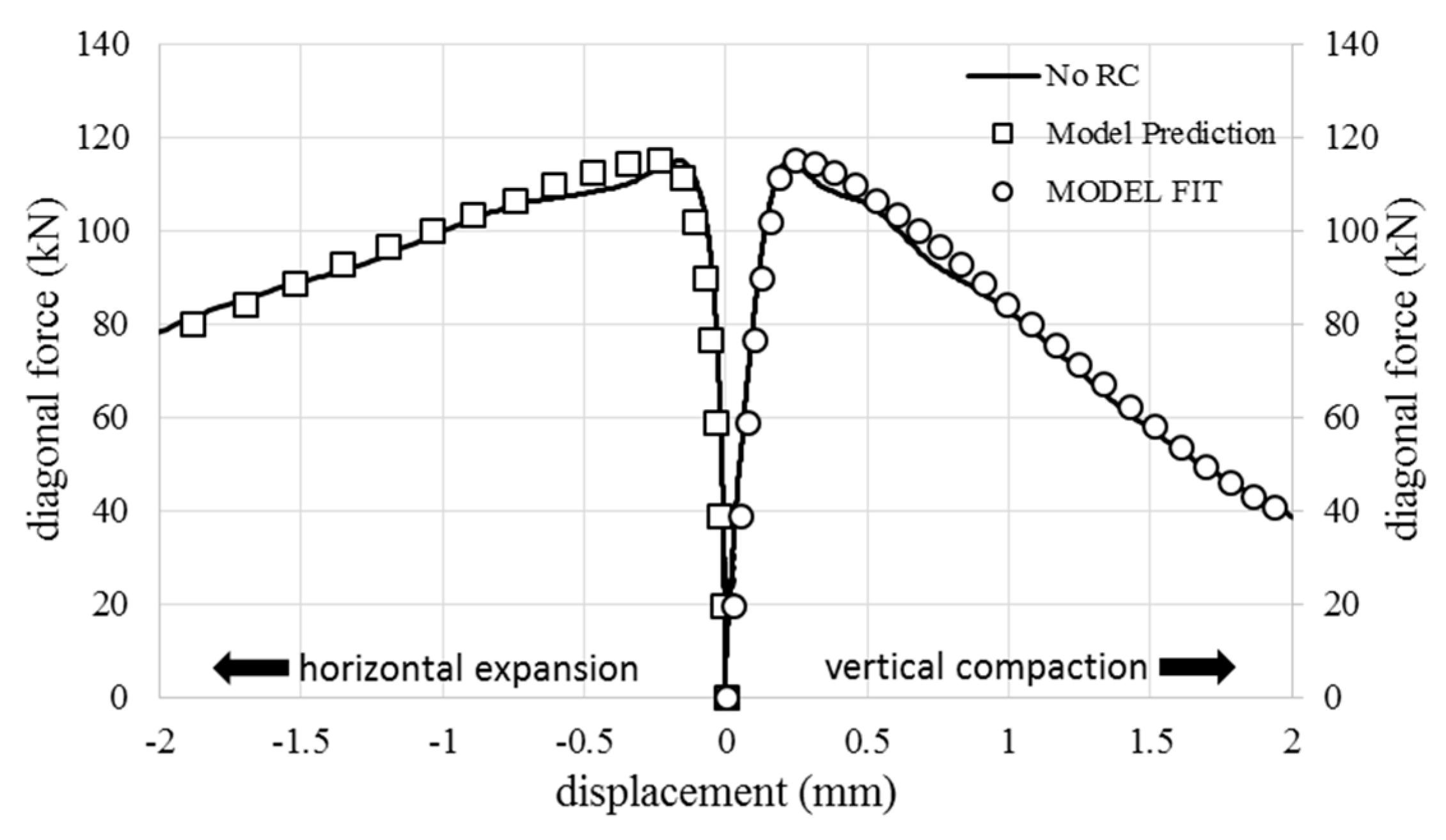
It is seen that the internal friction angle and the dilatation angle are almost the same; thus, optimization led to an associative flow rule for the Mohr-Coulomb model. The force-displacement data of the vertical compaction curve of one of the no-RC tests were used. The results are shown in Figure 5. In the same figure, the model fit for the horizontal expansion curve belonging to the same test is also depicted with the model prediction as well. Good agreement is observed regarding the optimized fit and the model prediction using the same set of parameters.
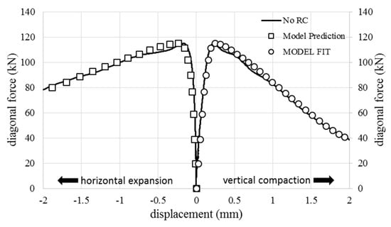
Figure 5.
No-RC test and optimized and predicted results.
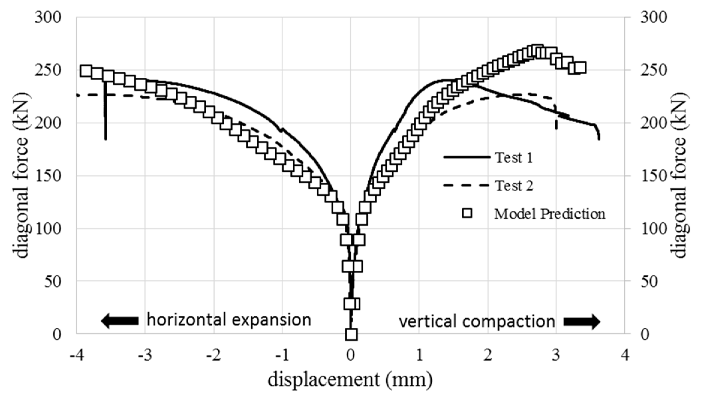
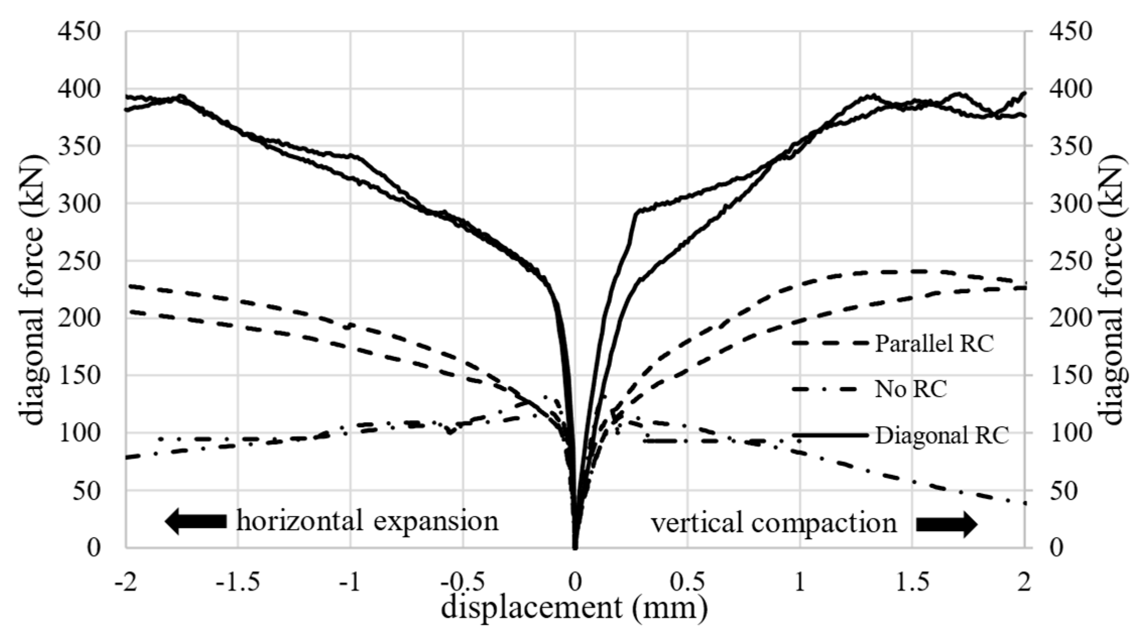
The same set of parameters were used to predict the response of the walls with reinforcement. Figure 6 and Figure 7 show the results of the prediction for the parallel reinforcement (P-RC) and diagonal reinforcement (D-RC) cases. In Figure 6, the sudden drops were due to immediate load reversal for safety reasons, as imminent failure was expected when cracking sounds were heard and the RC rods began to buckle. It is seen that given the differences between consecutive experimental results, the model predictions are reasonably good, and the model can capture the essential deformation characteristics of the masonry wall with reinforcement. Nevertheless, the trends of the experimental curves around the yield region agree reasonably well with the predictions. Figure 8 shows all the experimental results together, thus revealing the effect of reinforcement on the shear capacity and the energy dissipation of the masonry walls tested. From Figure 8, also the individualistic nature of each of the constructed walls can be seen as the results from the experiments of the same types of walls somehow have differences from each other in response. This is justified as the model wall is perfectly constructed (identical patterns of rows of mortar and bricks) with the algorithm, whereas this is not the case for the real walls. Thus, the fidelity of the model can be accepted.

Figure 6.
Parallel reinforcement (P-RC) tests and predicted results.

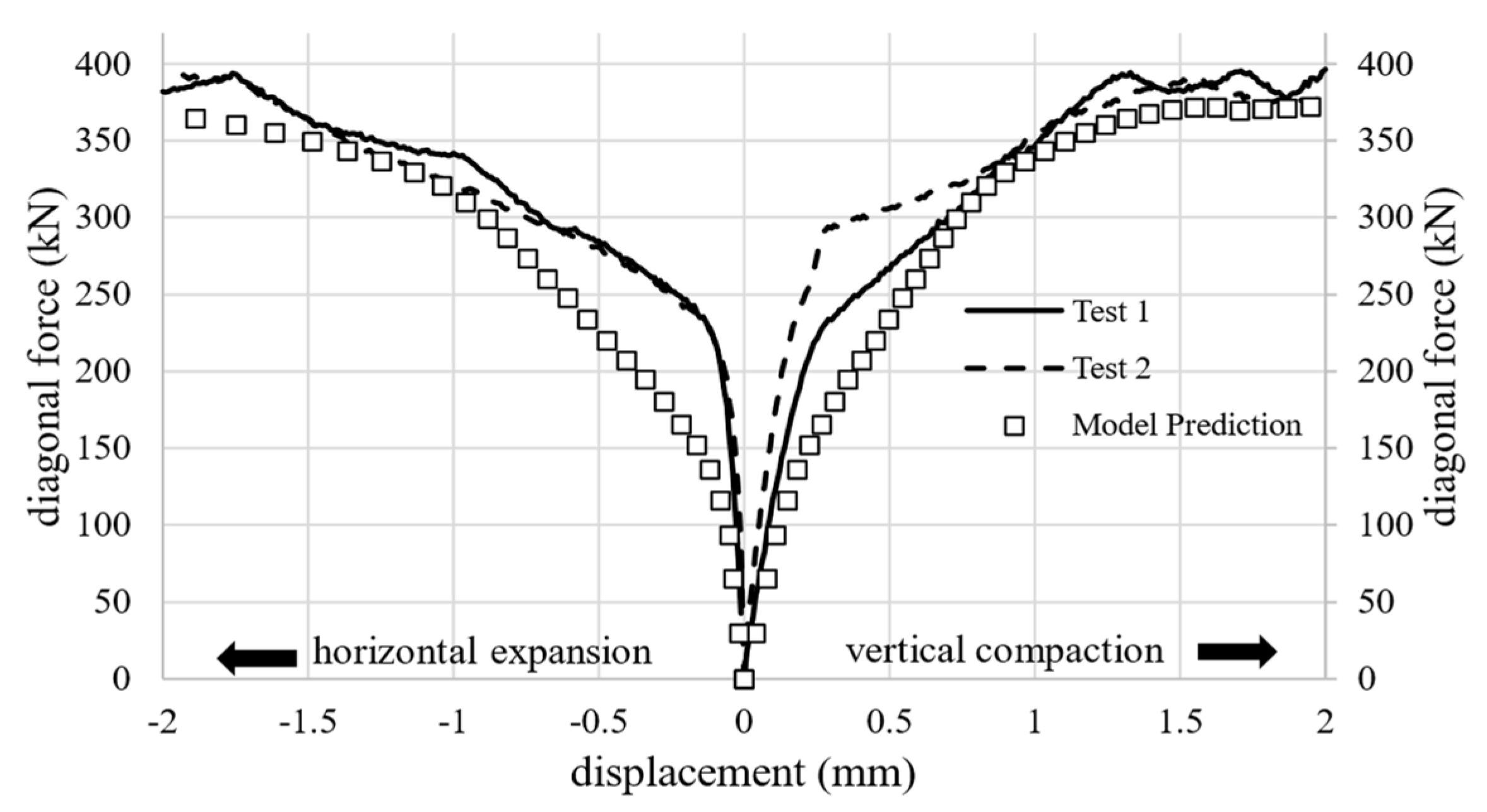
Figure 7.
Diagonal reinforcement (D-RC) tests and predicted results.
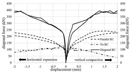
Figure 8.
Load-displacement results from all tests.
The model can also be used for the analysis of the failure patterns and the normal forces experienced by the reinforcement bars. For determining the failure patterns, the equivalent plastic strain variable () (denoted PEEQ in ABAQUS) can be used as an indicator and defined as in Equation (5):
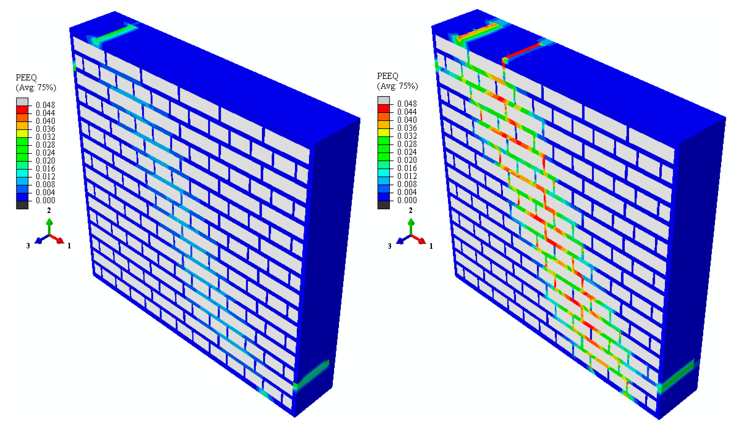
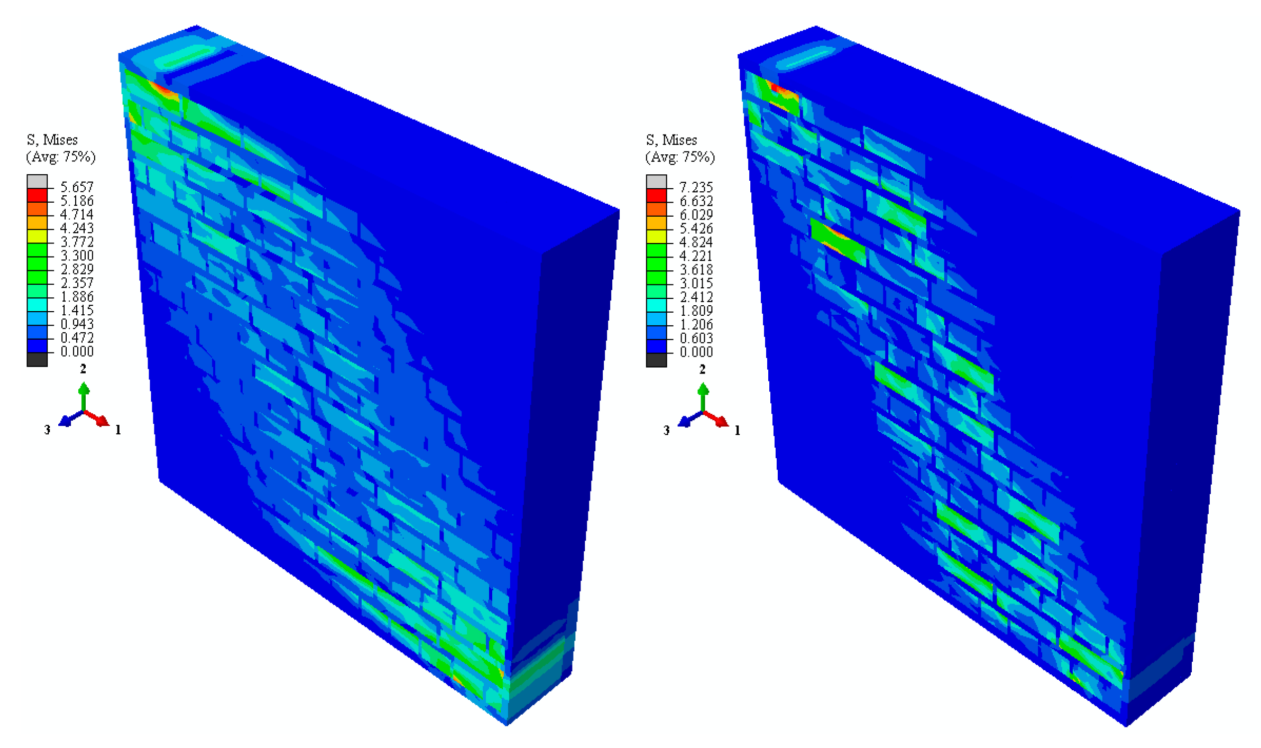
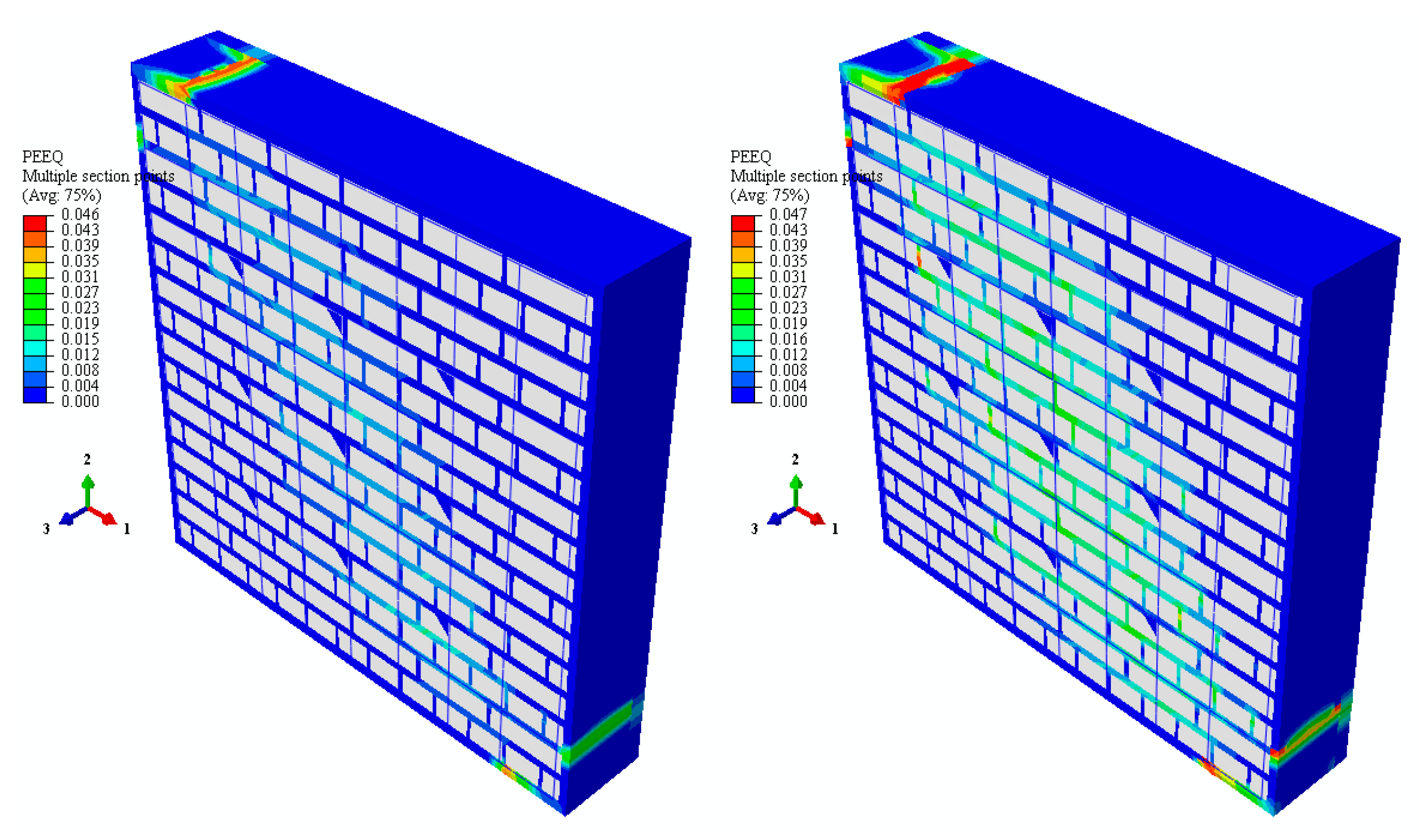
Figure 9 shows PEEQ-based failure patterns for diagonal load levels of 102 kN and 54 kN, respectively. The latter is for the softening part of the response as it is obvious from the increase in the intensity of the PEEQ. Plastic mortar joint failures are seen clearly, which form along a diagonal shear strip. The places where the caps engage the wall experiences high inelastic concentrations as expected. Figure 10 shows von Mises equivalent stresses for the same load levels. It is observed that the bricks sustained stress levels (≈2 MPa) below the limit of inelastic behavior. Thus, the elastic assumption for bricks is confirmed.
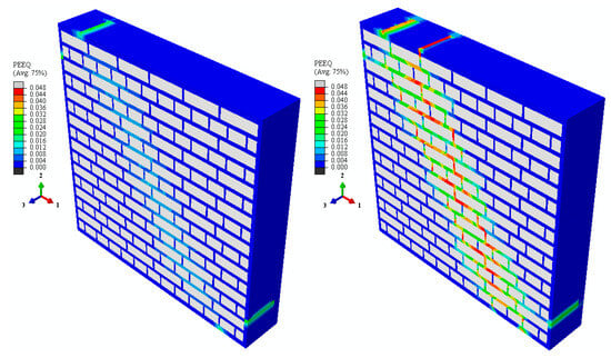
Figure 9.
No-RC equivalent plastic strain contours for load levels of 102 kN and 54 kN.

Figure 10.
No-RC von Mises equivalent stress contours for load levels of 102 kN and 54 kN.
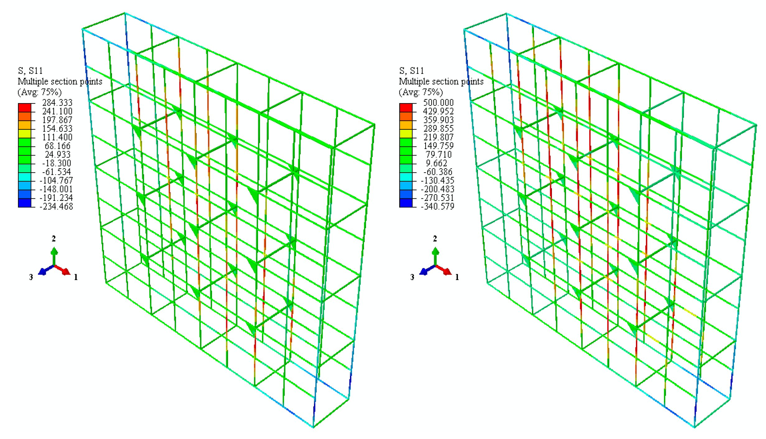
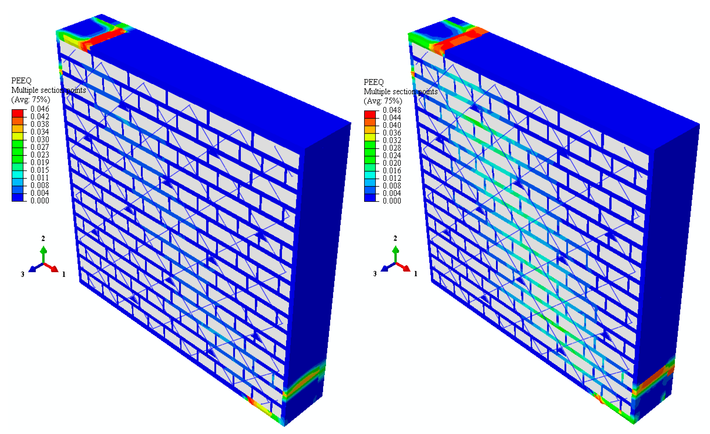
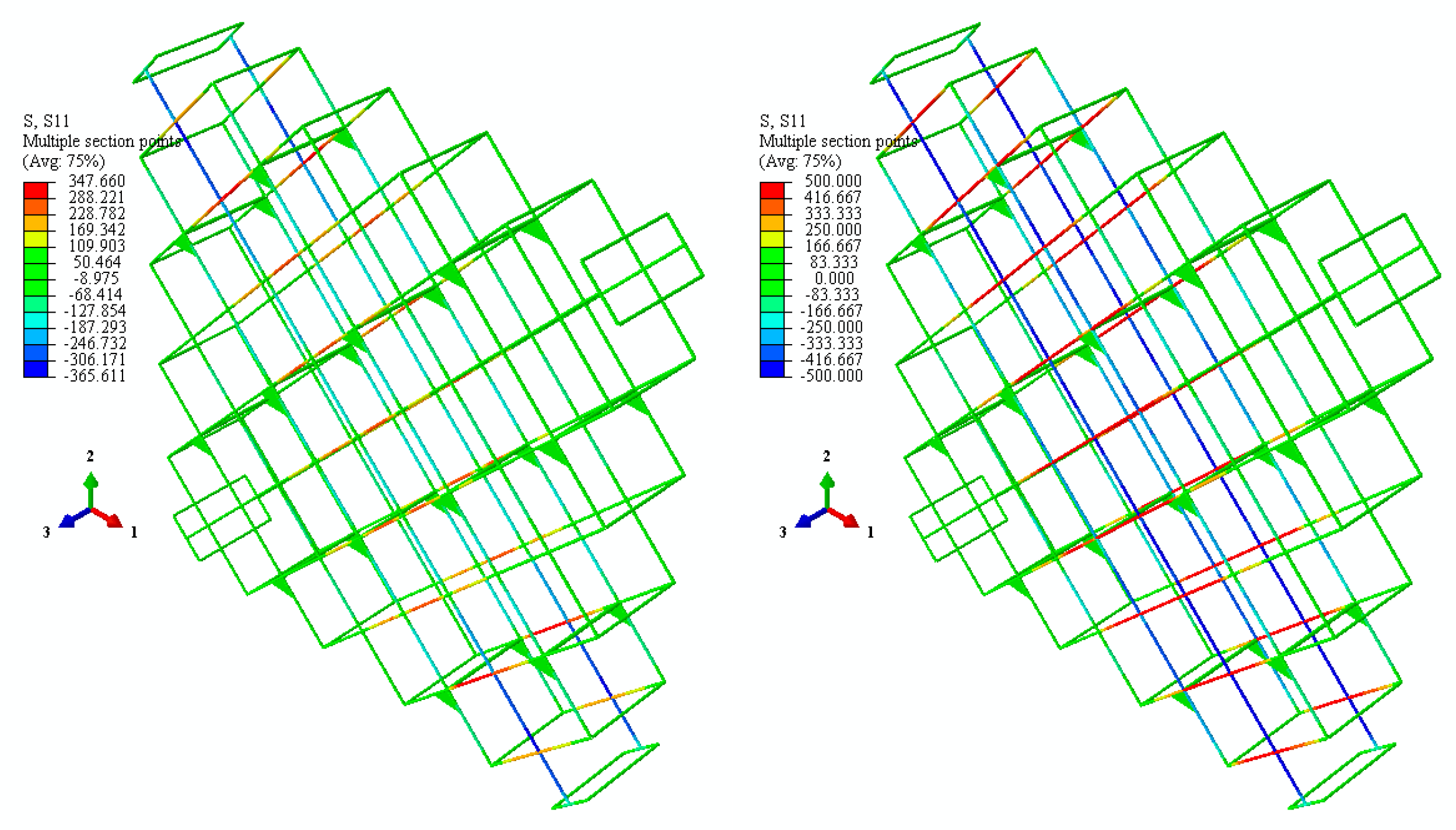
Figure 11 shows PEEQ values for the P-RC case for two different load levels of 131 kN and 231 kN. It is immediately seen that, compared to the No-RC case, PEEQ values are spread across larger areas. This is a primary indicator of the work of reinforcement as it spreads masonry shear over a diagonal area and also decreases the intensity of the plastic work. Figure 12 shows the normal stresses for the same case of P-RC for load levels of 131 kN and 231 kN. The pattern of tensile force development is as expected, and it is seen that the tensile limit is reached (≈500 MPa) for the load level of 231 kN. For this peak load level, the compression strength of the reinforcement is still not reached. Similar observations can be concluded for the D-RC case. Figure 13 shows the PEEQ values for load levels of 152 kN and 360 kN. The intensity of the PEEQ drops even more when compared to the P-RC case but the shear-effected area becomes narrower. This can be attributed to the fact that diagonally placed D-RC reinforcement concentrates stiffness into a narrower band along a diagonal line directly in line with the loading. As can be seen in Figure 14, normal stress patterns in reinforcement are also directly related to this fact. While diagonal reinforcement in line with loading reached a limit in compression, perpendicular reinforcements reached a tensile limit at the peak load of 360 kN. This fact indicates better utilization of the reinforcement both in tension and compression for D-RC when compared to P-RC. No yielding was observed in any reinforcement scheme for the connections between the front and back faces of walls.
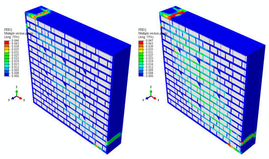
Figure 11.
P-RC equivalent plastic strain contours for load levels of 131 kN and 231 kN.
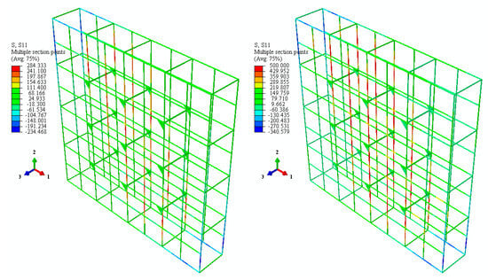
Figure 12.
P-RC RC normal stresses for load levels of 131 kN and 231 kN.
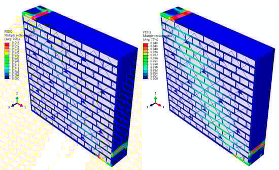
Figure 13.
D-RC equivalent plastic strain contours for load levels of 152 kN and 360 kN.
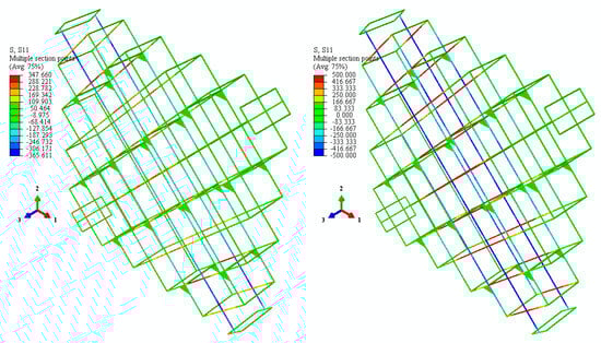
Figure 14.
D-RC RC normal stresses for load levels of 152 kN and 360 kN.
A final comparison point can be given on the deformations of the reinforcement. As observed in Figure 15, when the peak load is reached, reinforcements buckle close to the load application corners. In the model, out of plane deformations were also observed similar to the experiments (Figure 16).
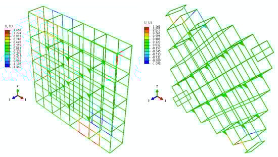
Figure 15.
P-RC (231 kN) D-RC (360 kN) out of plane deformations.
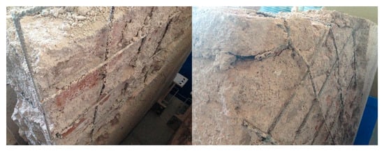
Figure 16.
P-RC and D-RC buckling of RC bars.
5. Conclusions
Masonry wall specimens constructed with Khorasan mortar were tested under diagonal compression in three configurations: unreinforced, edge-reinforced (P-RC), and diagonally reinforced (D-RC). The load-displacement behavior and damage progression were monitored throughout the experiments.
A three-dimensional micro-model was developed using the finite element method, incorporating a parametric Mohr-Coulomb material model. Model calibration was conducted via inverse analysis, employing the gradient-free Nelder-Mead optimization algorithm.
The main conclusions are as follows:
- Both reinforcement schemes led to significant improvements in shear strength and ductility.
- Diagonal reinforcement (D-RC) exhibited superior shear performance compared to edge-parallel reinforcement (P-RC).
- Reinforced specimens maintained structural integrity up to the onset of RC bar buckling, indicating a transition from brittle to ductile failure modes.
- The use of Khorasan mortar, characterized by lower stiffness than Portland cement, facilitated compatibility with historical masonry and enabled effective reinforcement integration without inducing damage to brick units.
- Brick units exhibited highly rigid behavior relative to the surrounding mortar.
- The Mohr-Coulomb material model, incorporating hardening and softening behavior, effectively captured the nonlinear response, particularly under vertical compression.
- The Nelder-Mead algorithm successfully optimized the model parameters, yielding a satisfactory match with experimental load-displacement curves and ultimate load levels, despite the inherent inhomogeneity of masonry.
As a continuation of this study, future research will include the use of a damage-plasticity-based model, such as the “concrete damaged plasticity” model, to better capture brittle behavior. Cyclic behavior will also be investigated in this context. Finally, a full-scale building model will be analyzed to assess the overall system performance under strong ground motion.
Author Contributions
Conceptualization, C.M.; methodology, C.M.; software, C.M. and M.O.Y.; validation, C.M. and M.O.Y.; writing—original draft preparation, C.M. and M.O. and M.O.Y.; writing—review and editing, C.M. and M.O. and M.O.Y.; visualization, M.O.Y. and M.O.; All authors have read and agreed to the published version of the manuscript.
Funding
This research received no external funding.
Data Availability Statement
The data presented in this study are available on request from the corresponding author due to privacy.
Acknowledgments
In memory of the late Turgut Kocaturk.
Conflicts of Interest
The authors declare no conflicts of interest.
References
- Ehsani, M.; Saadatmanesh, H.; Velazquez-Dimas, J. Behavior of retrofitted URM walls under simulated earthquake loading. J. Compos. Constr. 1999, 3, 134–142. [Google Scholar] [CrossRef]
- Velazquez-Dimas, J.; Ehsani, M. Modeling out-of-plane behavior of URM walls retrofitted with fiber composites. J. Compos. Constr. 2000, 4, 172–181. [Google Scholar] [CrossRef]
- ElGawady, M.A.; Lestuzzi, P.; Badoux, M. Shear strength of URM walls retrofitted using FRP. Eng. Struct. 2006, 28, 1658–1670. [Google Scholar] [CrossRef]
- Öztaş, V.; Torunbalcı, N. An Experimental Study of Strength Increase in Masonry Wall Reinforced by One-sided Khorasan Mortar with Steel Mesh. Civ. Eng. J. 2023, 9, 3233–3253. [Google Scholar] [CrossRef]
- Yardim, Y.; Lalaj, O. Shear strengthening of unreinforced masonry wall with different fiber reinforced mortar jacketing. Constr. Build. Mater. 2016, 102, 149–154. [Google Scholar] [CrossRef]
- Faella, C.; Martinelli, E.; Nigro, E.; Paciello, S. Shear capacity of masonry walls externally strengthened by a cement-based composite material: An experimental campaign. Constr. Build. Mater. 2010, 24, 84–93. [Google Scholar] [CrossRef]
- Bui, T.L.; Larbi, A.S.; Reboul, N.; Ferrier, E. Shear behaviour of masonry walls strengthened by external bonded FRP and TRC. Compos. Struct. 2015, 132, 923–932. [Google Scholar] [CrossRef]
- Wang, B.; Yin, S.; Qu, F.; Wang, F. Cyclic shear test and finite element analysis of TRC-reinforced damaged confined masonry walls. Constr. Build. Mater. 2024, 421, 135766. [Google Scholar] [CrossRef]
- Jafarian, S.; Esmaelian, M.; Shekarchi, M.; Ghassemieh, M. Performance of low-carbon textile-reinforced mortar: Out-of-plane response of strengthened masonry walls. Constr. Build. Mater. 2024, 415, 134904. [Google Scholar] [CrossRef]
- Khan, I.U.; Gul, A.; Shahzada, K.; Khan, K.; Khan, S.W.; Ullah, A.; Khan, F.A. Restoring seismic capacity of damaged dry stacked Self-Interlocking masonry structure through ferrocement overlay. Eng. Struct. 2023, 293, 116687. [Google Scholar] [CrossRef]
- Ma, P.; Xin, R.; Yao, J. Assessment of failure mode and seismic performance of damaged masonry structures retrofitted with grout-injected ferrocement overlay reinforcement (GFOR). Constr. Build. Mater. 2021, 305, 124778. [Google Scholar] [CrossRef]
- Gan, B.L.; Zhang, D.M.; Huang, Z.K.; Zheng, F.Y.; Zhu, R.; Zhang, W. Ontology-driven knowledge graph for decision-making in resilience enhancement of underground structures: Framework and application. Tunn. Undergr. Space Technol. 2025, 163, 106739. [Google Scholar] [CrossRef]
- Saingam, P.; Hlaing, H.H.; Suwannatrai, R.; Ejaz, A.; Hussain, Q.; Khan, K.; Joyklad, P. Enhancing the flexural behavior of brick masonry walls with ferrocement overlays and low-cost anchors. Case Stud. Constr. Mater. 2023, 19, e02558. [Google Scholar] [CrossRef]
- El-Diasity, M.; Okail, H.; Kamal, O.; Said, M. Structural performance of confined masonry walls retrofitted using ferrocement and GFRP under in-plane cyclic loading. Eng. Struct. 2015, 94, 54–69. [Google Scholar] [CrossRef]
- Marshall, O.S.; Sweeney, S.C.; Trovillion, J.C. Seismic rehabilitation of unreinforced masonry walls. In Proceedings of the Fourth International Symposium on Fiber Reinforced Polymer Reinforcement for Reinforced Concrete Structures, Baltimore, MD, USA, 31 October–5 November 1999; Volume 188, pp. 287–296. [Google Scholar] [CrossRef]
- Prawel, S.P.; Reinhorn, A.M.; Qazi, S. Upgrading the seismic resistance of unreinforced brick masonry using ferrocement coatings. In Proceedings of the 8th International Brick and Block Masonry Conference (8th IBMAC), Dublin, Ireland, 19–21 September 1988; Volume 2, pp. 785–791. [Google Scholar]
- Ashraf, M.; Khan, A.N.; Naseer, A.; Ali, Q.; Alam, B. Seismic behavior of unreinforced and confined brick masonry walls before and after ferrocement overlay retrofitting. Int. J. Arch. Herit. 2012, 6, 665–688. [Google Scholar] [CrossRef]
- Churilov, S.; Dumova-Jovanoska, E. In-plane shear behaviour of unreinforced and jacketed brick masonry walls. Soil Dyn. Earthq. Eng. 2013, 50, 85–105. [Google Scholar] [CrossRef]
- Kolsch, H. Carbon fiber cement matrix (CFCM) overlay system for masonry strengthening. J. Compos. Constr. 1998, 2, 105–109. [Google Scholar] [CrossRef]
- Luciano, R.; Sacco, E. Damage of masonry panels reinforced by FRP sheets. Int. J. Solids Struct. 1998, 35, 1723–1741. [Google Scholar] [CrossRef]
- Kalali, A.; Kabir, M.Z. Experimental response of double-wythe masonry panels strengthened with glass fiber reinforced polymers subjected to diagonal compression tests. Eng. Struct. 2012, 39, 24–37. [Google Scholar] [CrossRef]
- Hasnat, A.; Ahsan, R.; Yashin, S.M. Quasi-static in-plane behavior of full-scale unreinforced masonry walls retrofitted using ferrocement overlay. Asian J. Civ. Eng. 2022, 23, 649–664. [Google Scholar] [CrossRef]
- Pérez-Pinedo, L.; Sandoval, C.; Alvarado, R.; Vargas, L.; Calderón, S.; Bernat, E. Seismic strengthening of partially grouted masonry walls with openings: Evaluation of ferrocement and BTRM solutions. J. Build. Eng. 2024, 88, 109235. [Google Scholar] [CrossRef]
- Mukherjee, A.; Kaushik, H.B. Strengthening of unreinforced masonry buildings with ferrocement composite overlay: Material characterization and numerical study. Case Stud. Constr. Mater. 2025, 22, e04177. [Google Scholar] [CrossRef]
- Ehsani, M.R.; Saadatmanesh, H.; Al-Saidy, A. Shear behavior of URM retrofitted with FRP overlays. J. Compos. Constr. 1997, 1, 17–25. [Google Scholar] [CrossRef]
- Saadatmanesh, H. Extending service life of concrete and masonry structures with fiber composites. Constr. Build. Mater. 1997, 11, 327–335. [Google Scholar] [CrossRef]
- Albert, M.L.; Elwi, A.E.; Cheng, J.R. Strengthening of unreinforced masonry walls using FRPs. J. Compos. Constr. 2001, 5, 76–84. [Google Scholar] [CrossRef]
- ElGawady, M.A.; Lestuzzi, P.; Badoux, M. Dynamic versus static cyclic tests of masonry walls before and after retrofitting with GFRP. In Proceedings of the 13th World Conference on Earthquake Engineering, Vancouver, Canada, 1–6 August 2004; p. 2913. [Google Scholar]
- Capozucca, R. Double-leaf masonry walls under in-plane loading strengthened with GFRP/SRG strips. Eng. Struct. 2016, 128, 453–473. [Google Scholar] [CrossRef]
- Bouyahyaoui, A.; Elmalyh, S.; Cherradi, T. Behaviour of masonry walls reinforced by fiber reinforced polymers. Mater. Today Proc. 2023; in press (corrected proof). [Google Scholar] [CrossRef]
- Christensen, J.B.; Gilstrap, J.; Dolan, C.W. Composite materials reinforcement of existing masonry walls. J. Arch. Eng. 1996, 2, 63–70. [Google Scholar] [CrossRef]
- Hamilton III, H.R.; Dolan, C.W. Flexural capacity of glass FRP strengthened concrete masonry walls. J. Compos. Constr. 2001, 5, 170–178. [Google Scholar] [CrossRef]
- Luccioni, B.; Rougier, V.C. Shear behaviour of brick–mortar interface in CFRP retrofitted or repaired masonry. Int. J. Mech. Sci. 2010, 52, 602–611. [Google Scholar] [CrossRef]
- Wang, H.; Yu, J.; Dong, F.; Jiang, F.; Yu, K. Seismic shear behavior of masonry walls strengthened with engineered cementitious composites (ECC). J. Build. Eng. 2025, 104, 112230. [Google Scholar] [CrossRef]
- Xu, C.; Nehdi, M.L.; Wang, K.; Marani, A.; Zhang, L. Seismic behavior of autoclaved aerated concrete masonry walls reinforced with glass-fiber geogrid. Structures 2023, 58, 105367. [Google Scholar] [CrossRef]
- Capozucca, R. Experimental analysis of historic masonry walls reinforced by CFRP under in-plane cyclic loading. Compos. Struct. 2011, 94, 277–289. [Google Scholar] [CrossRef]
- Stratford, T.; Pascale, G.; Manfroni, O.; Bonfiglioli, B. Shear strengthening masonry panels with sheet glass-fiber reinforced polymer. J. Compos. Constr. 2004, 8, 434–443. [Google Scholar] [CrossRef]
- Briccoli Bati, S.; Rovero, L.; Tonietti, U. Strengthening masonry arches with composite materials. J. Compos. Constr. 2007, 11, 33–41. [Google Scholar] [CrossRef]
- Işıkdağ, B.; Topçu, İ.B. The effect of ground granulated blast-furnace slag on properties of Horasan mortar. Constr. Build. Mater. 2013, 40, 448–454. [Google Scholar] [CrossRef]
- Dinç-Şengönül, B.; Yüzer, N.; Şengönül, C.; Ulukaya, S.; Oktay, D.; Ündül, Ö. Behavior of grout injected solid stone masonry walls under in-plane loading. Structures 2023, 58, 105411. [Google Scholar] [CrossRef]
- Triantafillou, T.C. Strengthening of masonry structures using epoxy-bonded FRP laminates. J. Compos. Constr. 1998, 2, 96–104. [Google Scholar] [CrossRef]
- Corradi, M.; Castori, G.; Sisti, R.; Borri, A.; Pesce, G.L. Repair of block masonry panels with CFRP sheets. Materials 2019, 12, 2363. [Google Scholar] [CrossRef]
- Corbi, I. FRP reinforcement of masonry panels by means of C-fiber strips. Compos. Part B Eng. 2013, 47, 348–356. [Google Scholar] [CrossRef]
- Magenes, G.; Calvi, G.M. In-plane seismic response of brick masonry walls. Earthq. Eng. Struct. Dyn. 1997, 26, 1091–1112. [Google Scholar] [CrossRef]
- Wang, X.; Lam, C.C.; Iu, V.P.; Kou, K.P. Numerical study of NSM FRP Strengthened Masonry walls. In Structural Analysis of Historical Constructions; Springer: Berlin/Heidelberg, Germany, 2019; pp. 1670–1678. [Google Scholar] [CrossRef]
- Al-Jaberi, Z.; Myers, J.J.; El Gawady, M.A. Pseudo-static cyclic loading comparison of reinforced masonry walls strengthened with FRCM or NSM FRP. Constr. Build. Mater. 2018, 167, 482–495. [Google Scholar] [CrossRef]
- Konthesingha, K.M.C.; Masia, M.J.; Petersen, R.B.; Mojsilovic, N.; Simundic, G.; Page, A.W. Static cyclic in-plane shear response of damaged masonry walls retrofitted with NSM FRP strips–An experimental evaluation. Eng. Struct. 2013, 50, 126–136. [Google Scholar] [CrossRef]
- Abdulla, K.F.; Cunningham, L.S.; Gillie, M. Out-of-plane strengthening of adobe masonry using hemp fibre ropes: An experimental investigation. Eng. Struct. 2021, 245, 112931. [Google Scholar] [CrossRef]
- Lin, Y.W.; Wotherspoon, L.; Scott, A.; Ingham, J.M. In-plane strengthening of clay brick unreinforced masonry wallettes using ECC shotcrete. Eng. Struct. 2014, 66, 57–65. [Google Scholar] [CrossRef]
- Lin, Y.; Lawley, D.; Wotherspoon, L.; Ingham, J.M. Out-of-plane testing of unreinforced masonry walls strengthened using ECC shotcrete. Structures 2016, 7, 33–42. [Google Scholar] [CrossRef]
- Dassault Systèmes. Abaqus 2024 Documentation; Dassault Systèmes Simulia Corp.: Johnston, RI, USA, 2024. [Google Scholar]


Disclaimer/Publisher’s Note: The statements, opinions and data contained in all publications are solely those of the individual author(s) and contributor(s) and not of MDPI and/or the editor(s). MDPI and/or the editor(s) disclaim responsibility for any injury to people or property resulting from any ideas, methods, instructions or products referred to in the content. |
© 2025 by the authors. Licensee MDPI, Basel, Switzerland. This article is an open access article distributed under the terms and conditions of the Creative Commons Attribution (CC BY) license (https://creativecommons.org/licenses/by/4.0/).