Article

Simulation Study on Stability of Air-Supported Membrane Coal Storage Bin Under Fire Scenario

1
Department of Civil Engineering, Taiyuan University of Technology, Taiyuan 030024, China
2
The Institute of Architectural Design and Research, Taiyuan University of Technology, Taiyuan 030024, China
*
Author to whom correspondence should be addressed.
Buildings 2025, 15(10), 1734; https://doi.org/10.3390/buildings15101734
Submission received: 30 April 2025 / Revised: 15 May 2025 / Accepted: 18 May 2025 / Published: 20 May 2025
(This article belongs to the Section Building Structures)

Abstract

Air-supported membrane structures (ASMS) are widely applied in warehouses and large-span venues due to their lightweight and cost-effective nature. However, as a storage building with a lot of combustible material and significant fire hazards, it imposes stringent demands on structural stability and safety. This paper investigates the impact of fire-induced effects on stability using Fire Dynamics Simulator (FDS) software, with a case study focusing on an ASMS coal storage bin. The study comprises two key components: (1) internal pressure stability and (2) thermal stability. Results show that ambient temperature, leakage area and air supply govern non-fire pressure stability, with a 10 K increase reducing pressure by 9.4 Pa. During fires, HRR, location and growth type effect the stability of ASMS buildings. Thermal stability analysis reveals 6 m horizontal spacing can prevent coal ignition (<12.5 kW/m2, <100 °C), while 10 m vertical spacing can avoid PVC membrane pyrolysis. These findings provide critical design guidelines for ASMS fire protection, highlighting the necessity of asymmetric safety margins due to vertical–horizontal radiation anisotropy.

1. Introduction

As an innovative architectural form, air-supported membrane structures (ASMS) have experienced rapid development in China in recent years. In contrast to conventional structural systems that utilize steel or aluminum as primary load-bearing elements, ASMS buildings employ a specialized aluminum alloy clamping system to mechanically anchor the PVC membrane to reinforced concrete foundations. In addition, to ensure structural stability and optimal tensile–compressive performance, high-strength materials such as polyester fibers and carbon fibers are employed in ASMS buildings, offering both durability and mechanical resilience under operational loads [1]. Due to its advantages of light weight, large span, low cost and recyclable materials, it is widely used in various fields. The ASMS building is generally a large-space building with a relatively concentrated internal flow of people, which poses a great fire threat. In recent years, some scholars have carried out relevant research on the security risks exposed in the application of ASMSs.
Zhang P.W. (2014) studied the mechanical response of rectangular aerated membrane structure under fire through the analysis of fire resistance performance, and the fire scenario was set as the structural behavior evolution under the standard fire temperature rise curve (such as ISO 834) [2]. Jia Y.W. (2018) carried out a fire simulation of rectangular ASMSs based on FLUENT software, focusing on the characteristics of smoke propagation and temperature distribution under the action of local oil pool fire (HRR = 5 MW) [3]. Heng Z. (2020) used the CFD method to simulate the influence of the rapidly developing t2 fire (peak HRR = 15 MW) on the temperature field for the air-supported membrane structure in a large space, revealing the coupling effect between the fire source position and the structure geometry [4]. In addition, Yang W. and Guo Q.Z. et al. (2020) analyzed the evacuation efficiency of a university gymnasium under the condition of multiple fire sources (single HRR = 2.5 MW) through evacuation simulation, emphasizing the correlation between fire scenes and building functions [5]. While existing studies have investigated various aspects of fire behavior in membrane structures, several critical limitations remain. On the one hand, current research predominantly focuses on standardized fire curves (e.g., ISO 834) or simplified fire scenarios (e.g., fixed HRR pool fires), neglecting realistic fire dynamics and transient HRR variations in actual coal storage environments. On the other hand, prior works primarily examine either structural mechanical responses or smoke/temperature distributions in isolation, lacking a coupled analysis of aerodynamic–thermal–structural interactions.
Air-supported membrane structures (ASMSs) have gained widespread adoption in storage facilities and long-span venues, particularly for housing flammable materials, owing to their cost-effectiveness and rapid deployment [6]. However, the inherent flammability of membrane materials significantly elevates fire risks, potentially compromising structural integrity during combustion events. This investigation employs a computational fire modeling approach, utilizing Fire Dynamics Simulator (FDS) software, to systematically evaluate the stability of an ASMS coal storage bin under fire scenario, with particular emphasis on two critical failure dimensions: (1) internal pressure stability; (2) thermal stability. Through numerical simulations, the study quantitatively assesses the influence of key fire dynamics parameters on structural stability, while proposing optimized safety separation distances based on smoke management principles. The findings yield both theoretical advancements in understanding fire–structure interaction mechanisms and practical guidelines for enhancing the fire-resistant design of membrane-based industrial enclosures.

2. Model Building and Validation

2.1. Introduction of Numerical Simulation Methodologies

Numerical simulation methodologies have historically been categorized into three principal approaches: the finite difference method (FDM), Bessel multi-step method, and finite volume method (FVM). The FDM operates by discretizing derivative terms in partial differential equations through difference approximations, effectively transforming them into systems of algebraic equations. Demitrios S., Elliot R.W., Shashank V. et al. [7] developed a finite difference method (FDM)-based fire spread model that integrates coupled heat transfer equations for conduction, convection, and radiation. The model demonstrated high accuracy in simulating smoke transport within geometrically complex building spaces, with grid convergence analysis confirming numerical errors below 5% relative to benchmark solutions.
In contrast, the Bessel multi-step method represents a high-precision numerical integration scheme that leverages Bessel functions to enhance solution stability via iterative multi-step formulations. In the research of Doo H.H., the radiative transfer equation is discretized in angular coordinates using the Bessel multi-step method, which achieves a 40% computational acceleration in flame radiant heat flux calculations while maintaining equivalent accuracy compared to conventional discrete ordinates methods [8].
The FVM, grounded in fundamental conservation principles, discretizes the computational domain into finite control volumes and solves flux balance equations at cell interfaces, establishing itself as the methodology of choice for coupled physical phenomena including fire dynamics simulations and heat/mass transfer analyses. Each method exhibits distinct advantages: FDM provides mathematical transparency for regular geometries, Bessel multi-step methods offer superior performance for oscillatory systems, while FVM guarantees strict conservation properties essential for complex flow simulations. Therefore, based on the FVM, this paper will use Fire Dynamics Simulator (FDS) simulation software (Version 2024.2.1209) to carry out numerical simulation research on the stability of ASMS coal storage in fire scenarios.

2.2. The Governing Equation

FDS software is a computational fluid dynamics tool specifically designed for fire-driven flows. The solver is based on the finite volume method (FVM) which implements a low-Mach number formulation of the Navier–Stokes equations, originally developed by Rehm and Baum, to solve the coupled conservation equations governing mass, species, momentum and energy transport [9]. Turbulence modeling is addressed through a large eddy simulation (LES) approach incorporating the Deardorff subgrid-scale model [10] for turbulent viscosity closure. The numerical framework additionally integrates fundamental fire physics modules, including detailed combustion chemistry, fuel pyrolysis and radiative heat transfer models, enabling comprehensive simulation of fire growth, smoke propagation, and thermal radiation effects in built environments. This combination of advanced numerical schemes and physical models provides a powerful platform for the analysis of flue gas flow with thermal radiation in this study. The governing equations (equation of state, conservation of mass, species, linear momentum and energy) describing the physical problem under study are presented in Equations (1)–(5), as follows:
(a) Mass conservation:
ρ t + · ρ u = m b
where ρ is the density, u is the velocity and m b is the source term associated with the addition of mass from evaporating droplets or other subgrid-scale particles that represent, for example, fuel sprays and any other type of small, unresolvable object.
(b) Species conservation:
ρ γ α t + · ρ γ α u = · ρ D α γ α + m α + m b , α
where γ α and D α are the mass fraction and diffusivity of species, α . m α and m b , α are the mass production rate per unit volume of species α by chemical reactions and evaporating droplets/particles, respectively.
(c) Linear momentum conservation:
ρ u t + · u u = p + ρ g + f b + τ i j
where p is the pressure, g is the gravitational acceleration vector, f b is the external force vector and τ i j is the viscous stress tensor.
(d) Energy conservation:
ρ h s t + · ρ h s u = D p D t + q + q b · q
where h s is the enthalpy, q is the heat release rate per unit volume from a chemical reaction and q b is the energy transferred to subgrid-scale droplets and particles, and q represents the conductive, diffusive and radiative heat fluxes.
(e) Equation of state (ideal gas law):
p = ρ R T M
where R is the universal constant, T is the absolute temperature and M is the molecular weight of the gas mixture.

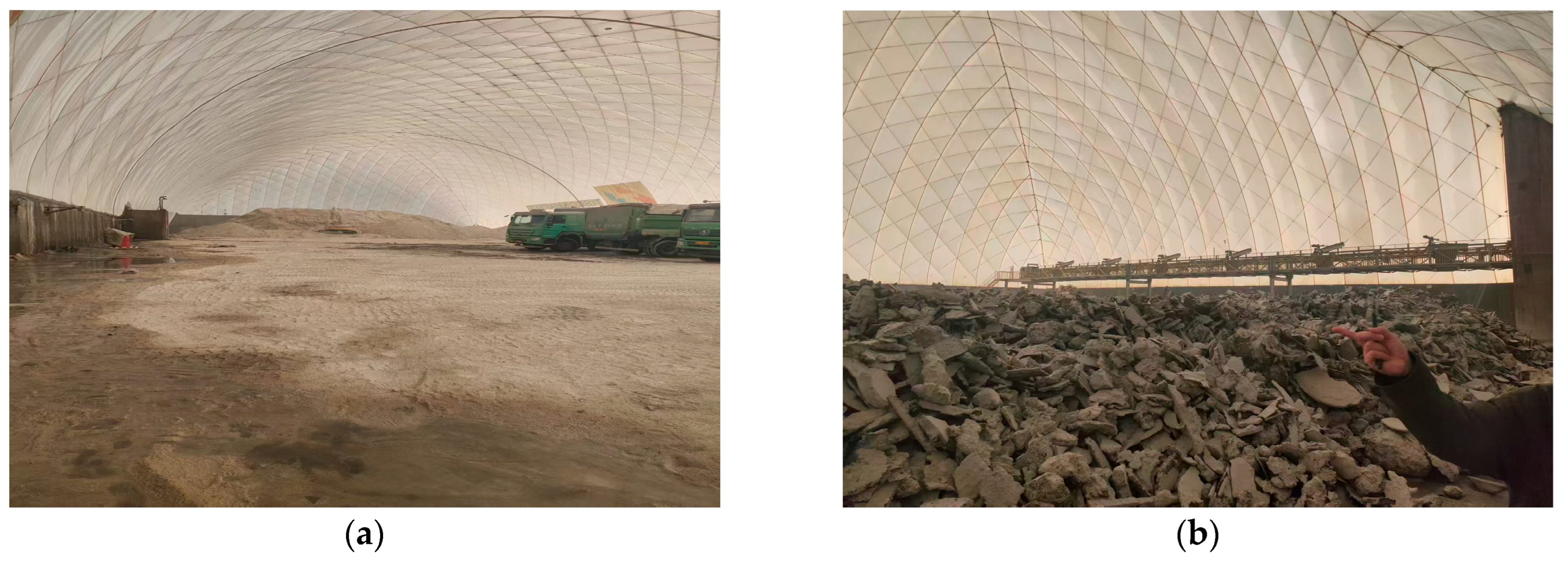
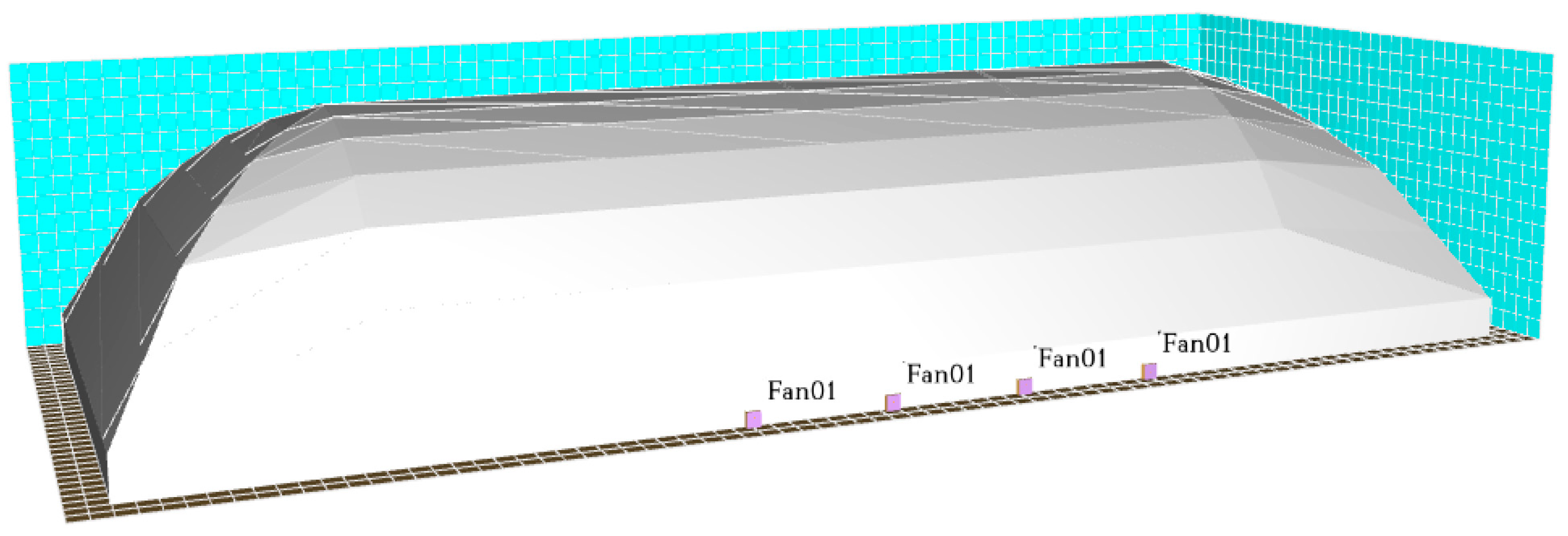
2.3. Construction of Air-Supported Membrane Coal Storage Bin Mathematical Model

Figure 1 shows part of the field diagram of the ASMS coal storage bin of the research object. This study employed Fire Dynamics Simulator (FDS) to develop a full-scale numerical fire model of the coal storage bunker, utilizing the as-built architectural drawings to ensure geometric fidelity. The computational domain precisely replicates the structural dimensions (L × W × H = 150 m × 60 m × 27.7 m), membrane material properties (thickness: 1.1 mm, density: a weight of 1350 g/m2, a thermal conductivity of 0.15 W/(m∙K) and a combustion heat of 11.3 MJ/kg).
The required grid size for different models can be calculated according to the calculation formula in the Pyrosim User Manual [11]. The required grid size for different models can be calculated according to Equation (6):
D * = Q ρ C p T g 2 5
where Q is the heat release rate of the fire source, ρ is the density of air and T is the indoor temperature at the time of the fire and Cp is the specific heat capacity of air.
If the simulation grid is set too large, the simulation results are not accurate enough and the error is large. Setting the grid too small will consume long simulation time, which is inefficient. Therefore, this study should carry out grid independence analysis, eliminate numerical errors as much as possible and ensure the reliability of the simulation results. Figure 2 is the model of the ASMS coal storage bin.
In an ASMS building, the internal pressure is maintained by mechanical ventilation systems. Figure 3 presents the field schematic of the mechanical air supply system implemented in the coal storage bin, where the ASMS buildings typically employ a multi-fan partitioned air supply configuration with fan selection based on the required internal pressure target values. Specifically, axial fans are recommended when the target internal pressure value is maintained below 300 Pa, as this configuration optimally meets the system’s aerodynamic requirements.
In this study, the term “internal pressure” specifically denotes the differential pressure between the interior and exterior environments of the structure. Upon reaching the target pressure differential, an automated control system activates mechanical exhaust fans through synchronized system linkage. These fans dynamically modulate the air exchange rate to compensate for pressure fluctuations, thereby maintaining structural equilibrium through regulation of the interior-exterior pressure gradient. The differential pressure is calculated as shown in Equation (7):
Q = Q i n Q o u t
According to the method introduced in the literature [12], this study uses FDS software to build a numerical fire model of an ASMS coal storage bin, aiming to study the effect of fire on the stability of it. However, before conducting stability simulation research, it is necessary to verify the constructed model and carry out the grid independence analysis to ensure the effectiveness and accuracy of subsequent research data.

2.4. Model Verification

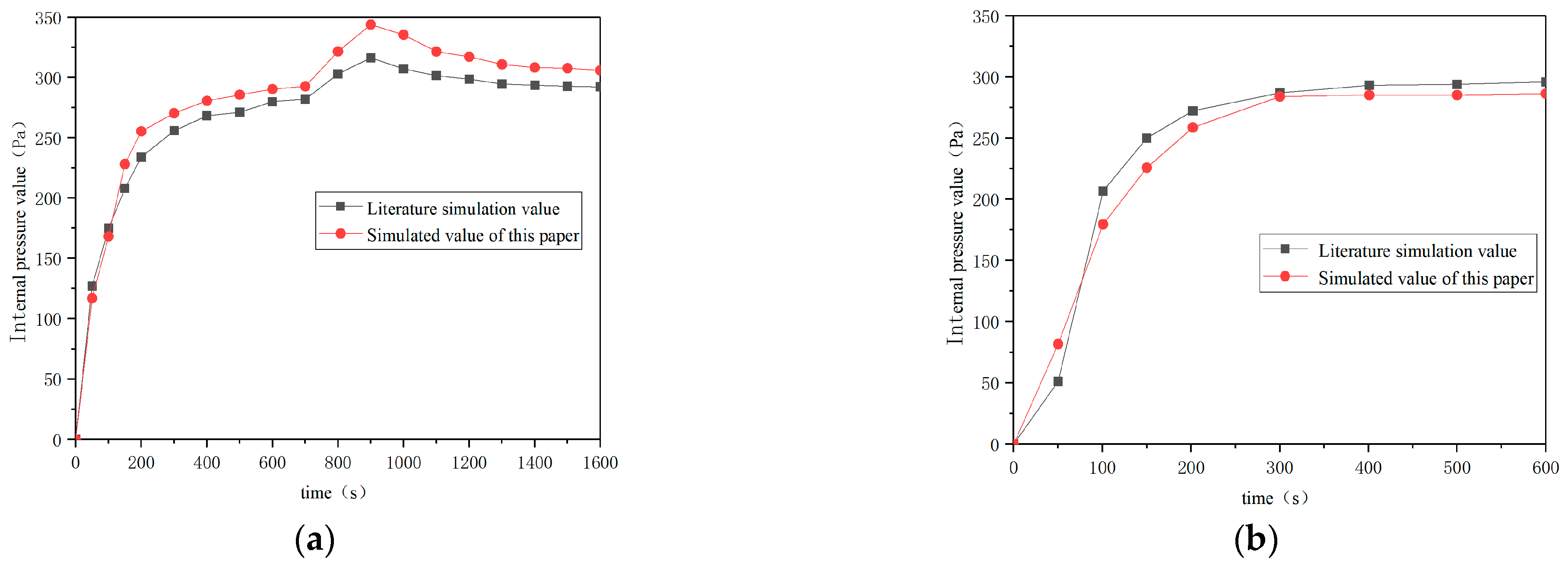
2.4.1. Differential Pressure Simulation Verification

Based on the design parameters established in reference [12], the simulation conditions are defined as follows: Under non-fire conditions, the ambient temperature is maintained at 293 K, with a building leakage area of 0.2 m2 and a mechanical air supply volume of 5 m3/s. For fire conditions, a fast-growing fire source (α = 0.044 kW/s2) with a peak heat release rate of 1.5 MW is positioned at the geometric center of the structure. The simulation working condition consisted of an 800 s steady-state initialization phase followed by ignition at t = 800 s.
Figure 4a,b present comparative analyses of internal pressure dynamics between the current model and reference data under non-fire and fire conditions, respectively. Model validation is achieved through pressure differential monitoring during both operational states. As demonstrated in Figure 4a, the maximum absolute pressure deviation between simulations is 21 Pa (relative error ≤ 7.8%). Figure 4b reveals strong agreement in pressure evolution trends, with a transient deviation of 28 Pa occurring at ignition (t = 800 s) that subsequently stabilized to maintain an overall relative error below 9.6%.

2.4.2. Grid Independence Analysis

Grid independence analysis constitutes an essential methodological procedure to ensure the reliability and scientific rigor of computational fire dynamics simulations, given that the finite volume method (FVM) implemented in FDS for governing equation discretization exhibits strong dependence on mesh resolution for accurate derivative approximation. This investigation systematically evaluates this relationship through a carefully designed parametric study featuring a 4 m × 4 m square fire source with a total heat release rate (HRR) of 3 MW positioned at the center of an air-supported membrane coal bin. Temperature monitoring probes are strategically distributed above the combustion zone to record the change in temperature under five distinct grid resolutions (0.1 m, 0.5 m, 0.75 m, 1.0 m and 2.0 m) throughout a 600 s simulation period, enabling comprehensive assessment of spatial discretization effects on temperature field predictions. The analysis focused on terminal temperature values at t = 600 s, with comparative results presented in Table 1 demonstrating that finer grid resolutions yield improved convergence behavior of temperature evolution curves and reduced relative errors. When the grid is less than or equal to 0.5 m, the temperature gradually converges, and the relative error is not more than 1.7%. Based on the dual considerations of computational accuracy and resource efficiency, an optimal grid size of 0.5 m was selected for the final simulations, corresponding to a total of 2,578,560 computational cells that satisfy both the Courant–Friedrichs–Lewy (CFL) stability condition.

3. Study on Stability of Internal Pressure

Following the successful validation of the coal storage bin model, this section investigates the internal pressure stability of the ASMS under two distinct operational scenarios: non-fire and fire conditions. For the non-fire condition analysis, three critical parameters are systematically examined: (1) ambient temperature; (2) mechanical air supply volume; (3) building equivalent leakage area [13]. Notably, the theoretical case of zero leakage area (0 m2) is excluded from consideration due to its physical impossibility in actual structures.
Unlike mechanically controlled indoor ventilation systems—where fan-generated airflow rates and velocities are precisely regulated—external wind conditions exhibit inherent stochastic variability, both temporally and spatially, making them uncontrollable in real-world scenarios. While external wind speed and pressure represent transient, stochastic parameters that significantly influence structural stability, their impact on internal pressure equilibrium has been largely overlooked in prior fire simulation research. This omission stems from the inherent complexities of modeling wind–structure–fire interactions, particularly for ASMS buildings where wind-induced fluctuations may couple nonlinearly with thermal buoyancy effects. Therefore, this study excludes the influence of external wind on the stability of ASMS buildings.
As detailed in Table 2, 20 working conditions are established to evaluate pressure stability under non-fire conditions. This designed approach enables rigorous quantification of each parameter’s influence on the structural pressure dynamics.

3.1. Simulation of Internal Pressure Under No-Fire Condition

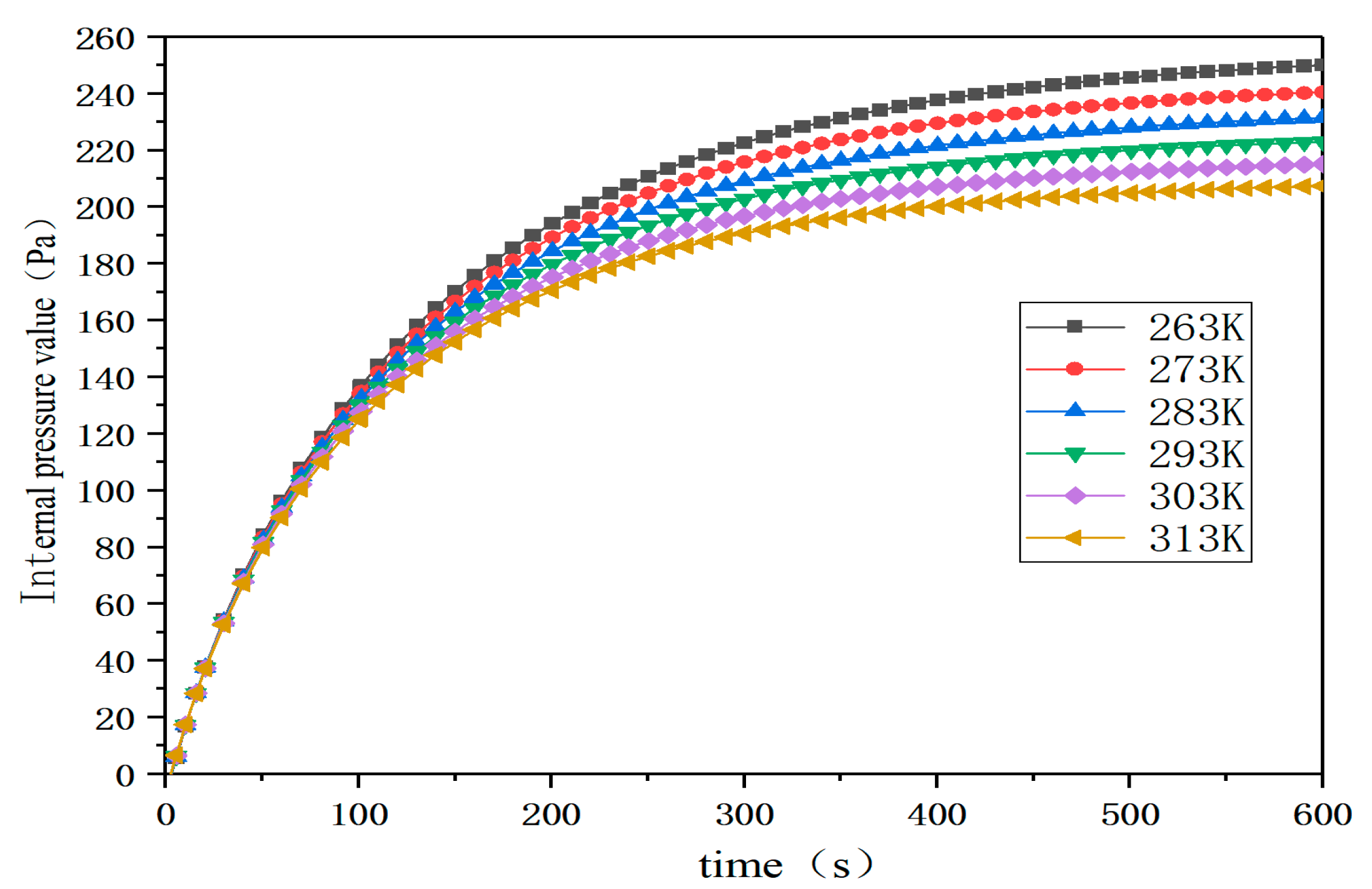
3.1.1. Influence of Ambient Temperature on Internal Pressure

This section systematically investigates the critical factors influencing internal pressure stability in ASMS coal storage bin under non-fire conditions. A study is conducted with the following parameter design: ambient temperature range is 263 K to 313 K (50 K gradient), leakage area is 0.2 m2 and air supply volume is 4 m3/s. The duration of all simulated conditions is 600 s.
Figure 5 demonstrates the temperature-dependent pressure characteristics under constant air supply volume (4 m3/s) and leakage area (0.2 m2). The results show that the internal pressure is stable at all temperatures with a stable value between 200 and 250 Pa at a supply air volume of 4 m3/s and a building leakage area of 0.2 m2. As the temperature increases, the stable value of internal pressure decreases. The internal pressure is the lowest at 207 Pa when ambient temperature is 313 K. The highest internal pressure is 250 Pa when ambient temperature is 263 K. For every 10 K increase in temperature, the stable value of internal pressure decreases by about 9.2 Pa. This indicates that a higher ambient temperature leads to a lower stable value of internal pressure and vice versa.

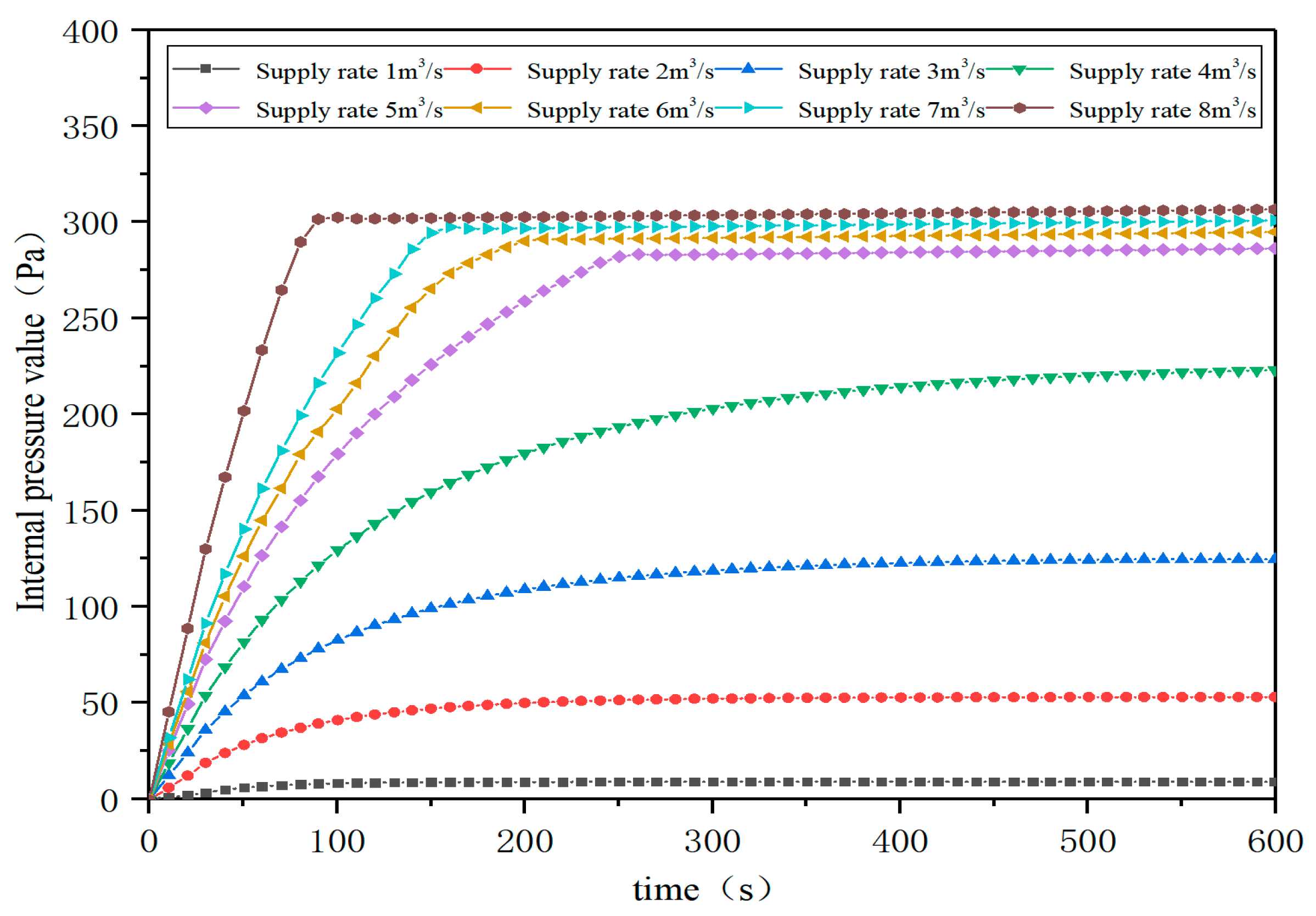
3.1.2. Influence of Mechanical Air Supply Volume on Internal Pressure

To study the effect of mechanical air supply volume on internal pressure stability in the building, the simulation parameters are set as follows: air supply gradient of 1~8 m3/s, equivalent leakage area of 0.2 m2, ambient temperature of 293 K and simulation duration of 600 s.
Figure 6 shows the variation in internal pressure under different air supply volumes. In the case of small flow volume (Q ≤ 3 m3/s), the internal pressure is rapidly stable but less than 250 Pa. In medium flow (Q 4~5 m3/s), the internal pressure stability value is increased and the time to reach stability is shortened. The internal pressure of large flow (Q 6~8 m3/s) quickly reaches the design pressure. The larger the air supply volume, the shorter the stable time and the higher the steady internal pressure. This is attributed to the increased internal air flow velocity caused by the increased air supply. In practical applications, it is necessary to choose the appropriate air supply volume according to the specific situation to ensure the stability and safety of the internal pressure.

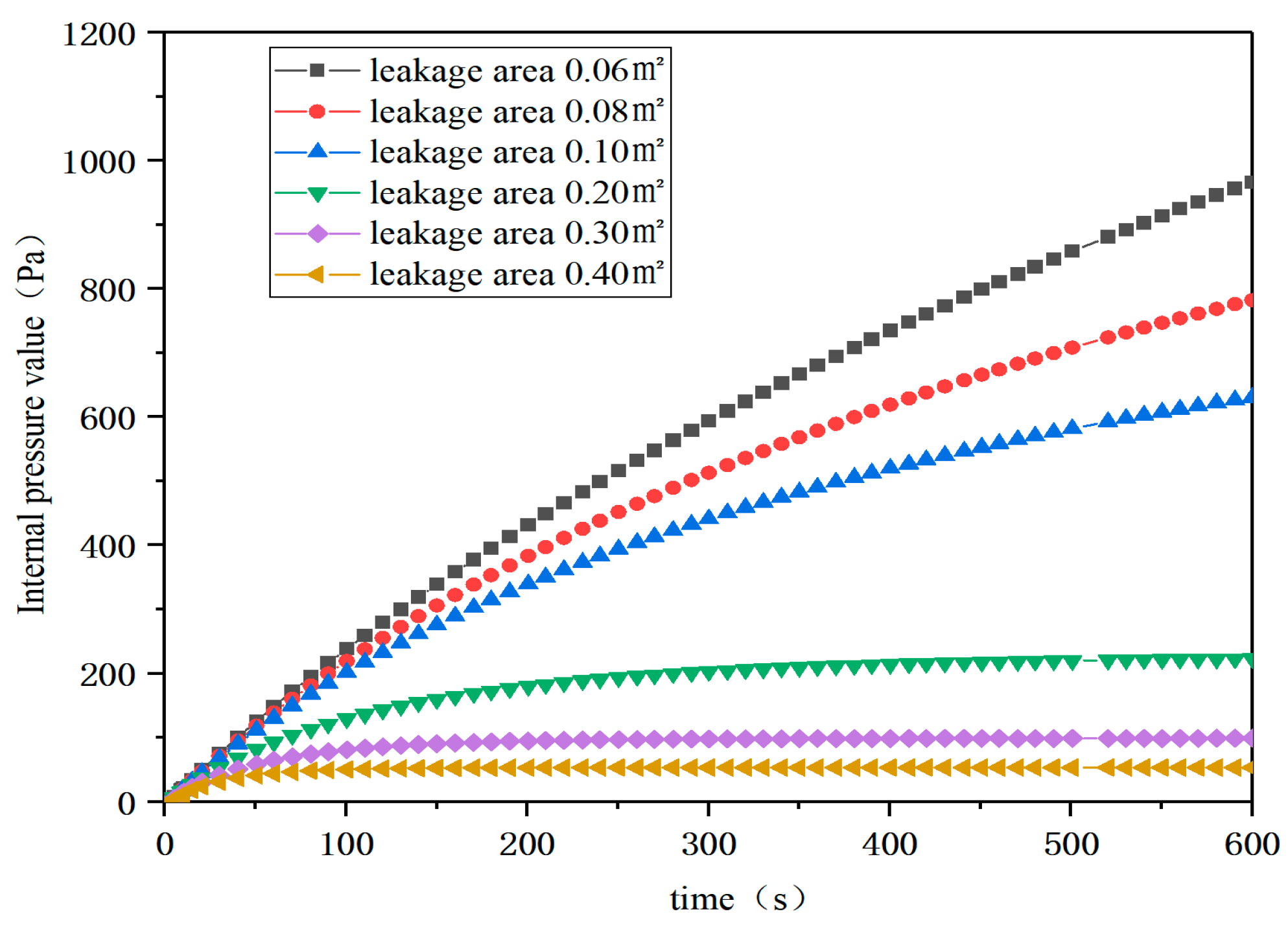
3.1.3. Influence of Leakage Area on Internal Pressure

The leakage area of buildings increases with the increase in volume [14]. In this study, the operating conditions with different leakage areas are set by keeping the mechanical air intake and ambient temperature constant. The leakage area of the building is 0.06 m2, 0.08 m2, 0.1 m2, 0.2 m2, 0.3 m2 and 0.4 m2 respectively. Figure 7 shows that the small leakage area (≤0.2 m2) causes the internal pressure to continue to rise, and there is no sign of stability. The large leakage area (0.2~0.4 m2) makes the internal pressure reach a stable value under certain conditions and the larger the leakage area, the lower the stable value. For example, when the leakage area is 0.2 m2, the stable value of internal pressure is 223 Pa; when the leakage area is 0.06 m2, it drops to 53 Pa.

3.2. Simulation of Internal Pressure Under Fire Condition

In view of the fire condition, this study selects three influencing parameters: fire source heat release rate (HRR), fire growth factor and fire source position [15] to explore the influence of three parameters on the internal pressure stability of ASMS buildings. The list of fire conditions is shown in Table 3. The ASMS coal storage bin is divided into five regions (Figure 8) and fire sources are set in different regions.

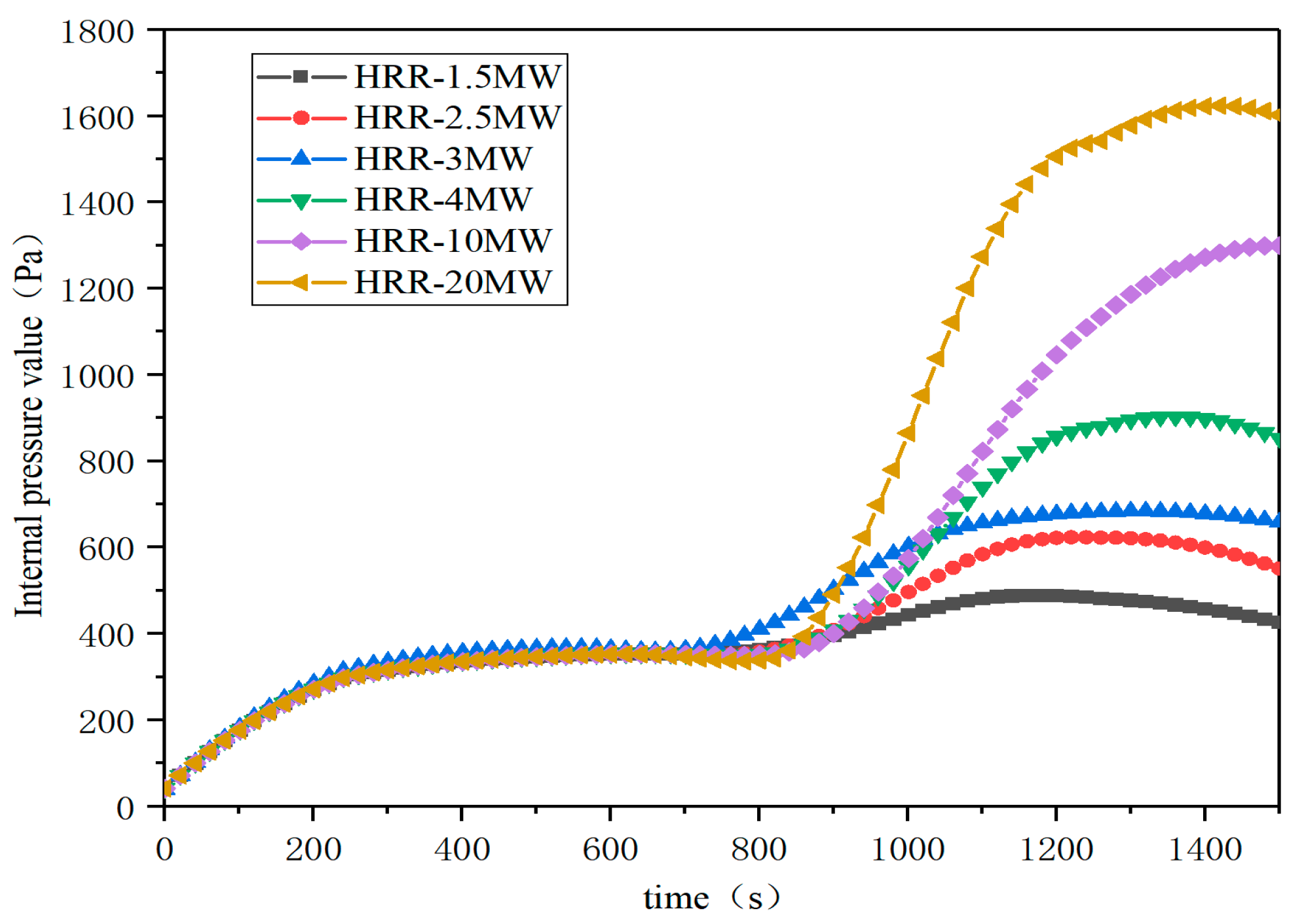
3.2.1. Influence of Heat Release Rate of Fire Source on Internal Pressure

Fire source is set in 3 area, the fire growth factor is selected as fast fire and the heat release rate of the fire source is set as 1.5 MW, 2.5 MW, 3 MW, 4 MW, 10 MW and 20 MW to explore the influence of the heat release rate of the fire source on the internal pressure stability in the ASMS coal storage bin. The simulation time is 1600 s. The first 800 s is the normal operation condition and the ignition is fired at the 800 s.
Figure 9 shows the effect of the heat release rate of the fire source on the internal pressure of the ASMS building. The result shows that the heat release rate of the fire source from 1.5 MW to 4 MW causes the internal pressure to rise quickly to the peak value and then decrease and stabilize. The peak internal pressure is 440 Pa at 1.5 MW and 886 Pa at 4 MW. The higher the heat release rate of the fire source, the greater the peak value of the internal pressure and the longer the time to reach steady state. At 10 MW and 20 MW working conditions, the internal pressure increases rapidly and no stable trend is observed for 800 s.

3.2.2. Influence of Fire Growth Coefficient on Internal Pressure

The fire source is set in 3 area with an HRR of 2.5 MW. Figure 10 shows that different fire types affect the internal pressure. The simulation reveals that the internal pressure rises slowly under slow fire and does not reach the peak at 1200 s. Under the conditions of medium, fast and ultra-fast fire, the internal pressure generally rises and the internal pressure of ultra-fast fire increases the fastest. This indicates that the combustion characteristics of fire load determine the change in internal pressure: materials with low combustion rate such as hardwood furniture have little effect, while materials with rapid heat release such as PVC increase the internal pressure sharply.

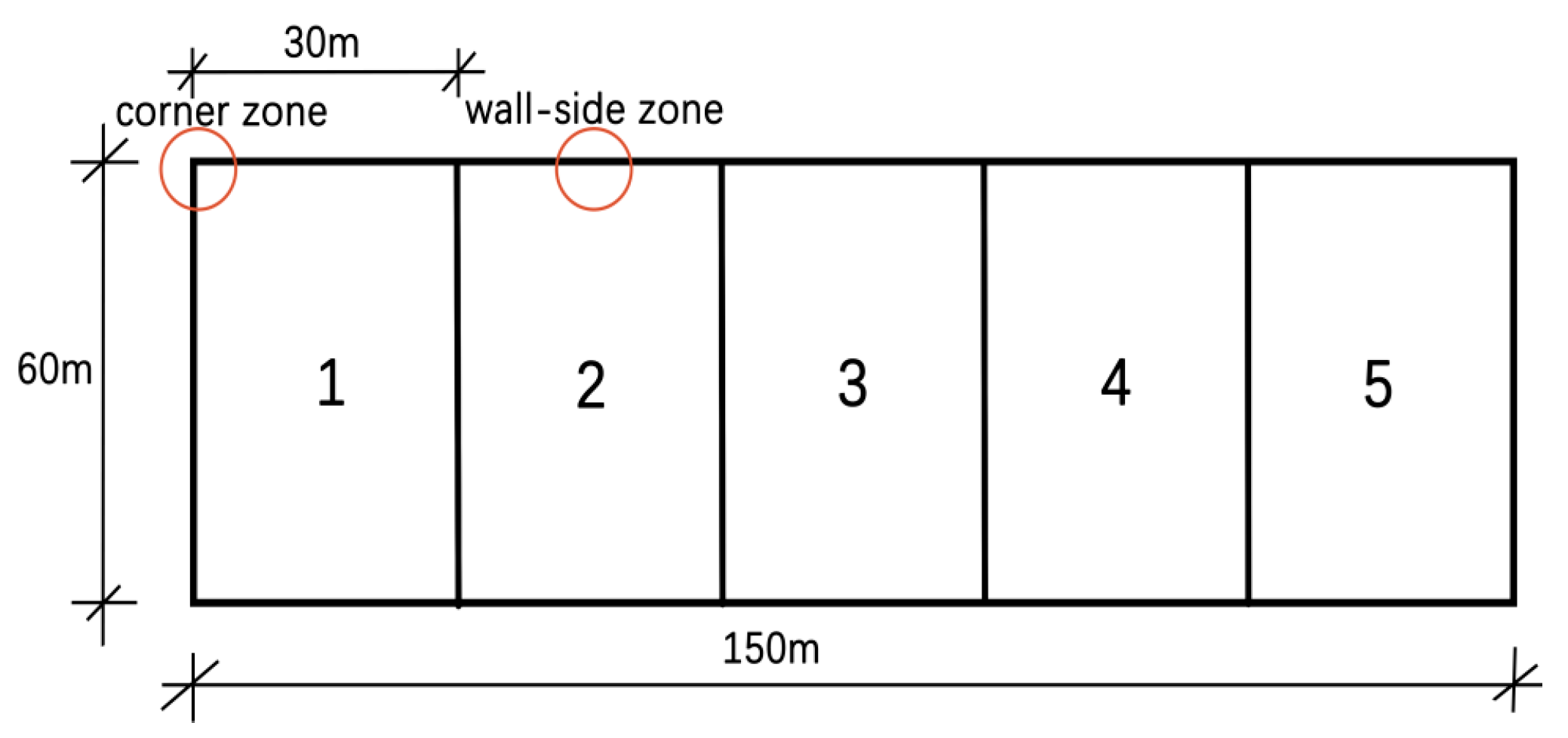
3.2.3. Influence of Fire Source Position on Internal Pressure

In the study, the fire source is set in five locations, which are area 1, area 2, area 3, wall edge area and corner area. By setting up a control simulation, the influence of the fire source position on the pressure stability of the building is explored. In this study, the HRR was 2.5 MW and the fire growth factor was 0.044 kW/s2.
Figure 11 shows the effect of different fire source locations on the internal pressure. Prior to ignition, the internal pressure reaches a peak of 350 Pa around 500 s. After ignition, the internal pressure rises rapidly, but the growth rate and peak value vary according to the location of the fire source. In the corner fire, the internal pressure increases the slowest and the peak value is 560 Pa. However, during the fire in 3 area, the internal pressure increases rapidly and reaches a peak of 620 Pa. The thermal plume generated by the central fire source and the availability of the top space lead to heat accumulation, accelerating air warming and rapid internal pressure growth. In contrast, in corner and wall fires, the smoke diffusion is limited, the heat distribution is dispersed, and some of the heat is absorbed or lost by the wall, resulting in a slower increase in internal pressure.

3.3. Simulation of Thermal Stability

Based on the fire condition, the radiation model of ASMS coal storage bin is constructed, as shown in Figure 12. By setting thermocouple detection points (Figure 13), the surface temperature of adjacent coal piles and the thermal radiation intensity received by the PVC membrane surface are monitored to explore the influence of fire on the thermal stability of ASMS coal storage bin. Through the double threshold criterion of critical heat radiation intensity and critical pyrolysis temperature [16], the ignition range between combustibles is evaluated, and the safety protection distance that combustibles should maintain is determined to suppress the risk of fire spread.
The fire risk of the coal pile in the ASMS storage bin is affected by multiple factors:
  • There are various types of coal in the coal storage bin with different ignition points ranging from 250~300 °C for lignite to more than 400 °C [17]. This affects the ignition threshold of the coal pile under thermal radiation.
  • Critical condition of coal pile spontaneous combustion: The spontaneous combustion of the coal pile is due to the accumulation of heat generated by the reaction between coal and oxygen [18]. When the packing density exceeds 1.2 t/m3 or the ventilation condition is poor, the heat is not easily emitted, resulting in a sharp rise in internal temperature. The study shows that the critical temperature of coal pile spontaneous combustion is between 100 °C and 200 °C.
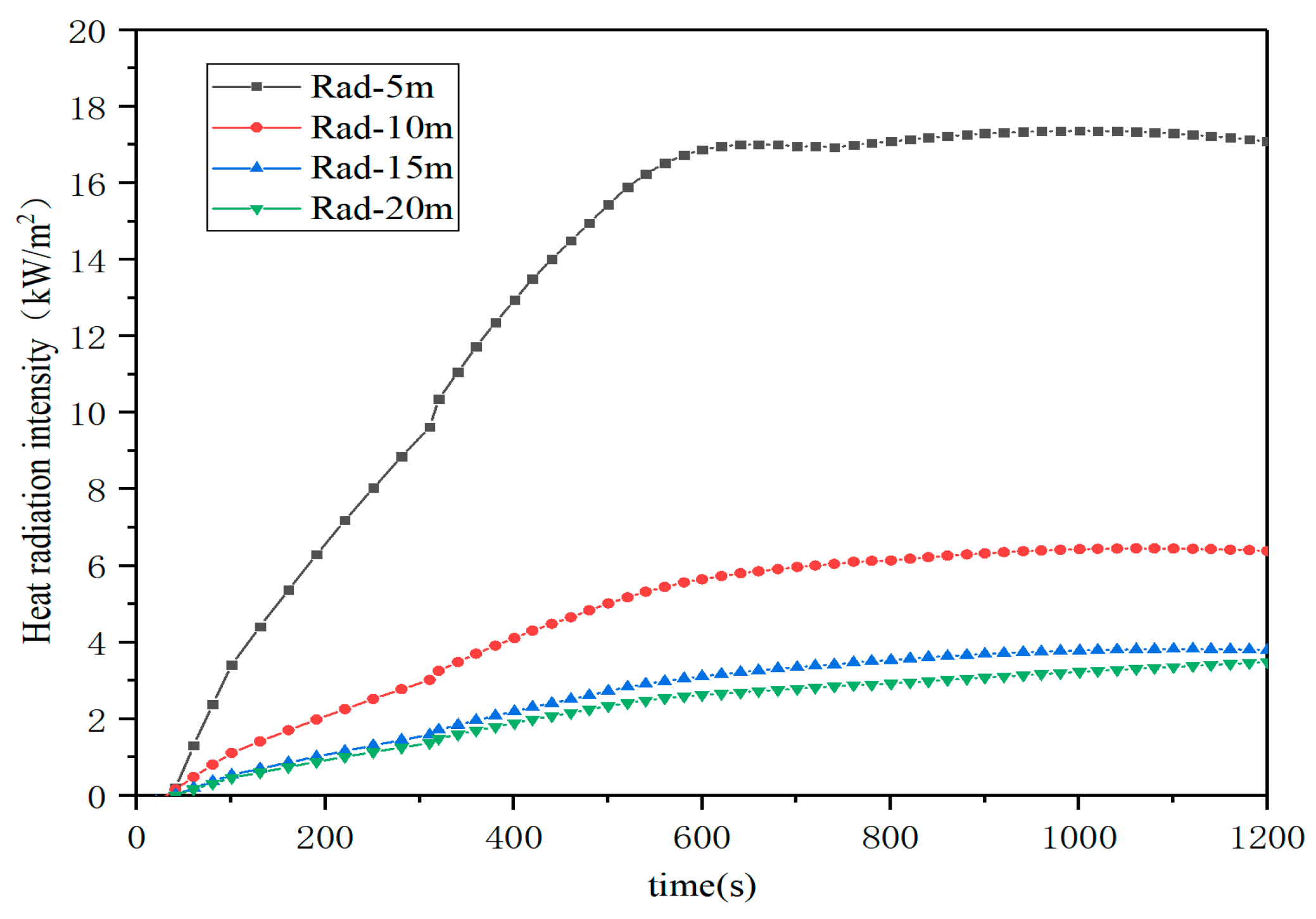
  • Heat radiation ignition: According to the literature [2,19], PVC membrane material begins pyrolysis significantly at 250–300 °C or when the heat radiation intensity received by the PVC membrane material exceeds 12.5 kW/m2, and the peak mass loss rate appears at 350 °C. Based on a comprehensive review of thermogravimetric analysis (TGA) data and prior experimental studies [10,20], the critical pyrolysis threshold for the PVC membrane material in this investigation was conservatively established at 250 °C. The selection of this value aligns with established industry standards [21] while accounting for potential uncertainties in real-world fire dynamics through the incorporation of a 10% safety margin below the 275 °C failure point observed in accelerated aging tests.
  • The formula for calculating the thermal radiation intensity received by the PVC membrane surface is as follows [22]:
q = q s + q f = ε × σ × T s 4 × F s + Q 12 π R 2
where q is the thermal radiation received on the membrane surface, kW/m2; q s is thermal radiation from the flue gas layer, kW//m2; and q f is thermal radiation from a fire source, kW/m2. ε is emissivity of the hot flue gas layer and T s is the absolute temperature of the hot flue gas layer. σ is the poznauru constant, 5.67 × 10 11 k W m 2 · K 4 . F s is the angular coefficient of radiation between the hot smoke layer and the combustible substance. R is the distance between combustible material and fire source, m.
This study systematically investigates fire propagation characteristics by examining three critical spatial parameters:
  • The horizontal distance between the ignition coal pile and the adjacent coal piles;
  • The distance from the ignition source to the side walls;
  • The vertical distance between the burning coal pile and roof PVC membrane surface.
Through controlled variation of these parameters (as detailed in Table 4), we quantitatively analyzed their influence on fire spread suppression and ultimately determined optimal safety distances for effective fire containment in the coal storage bin.

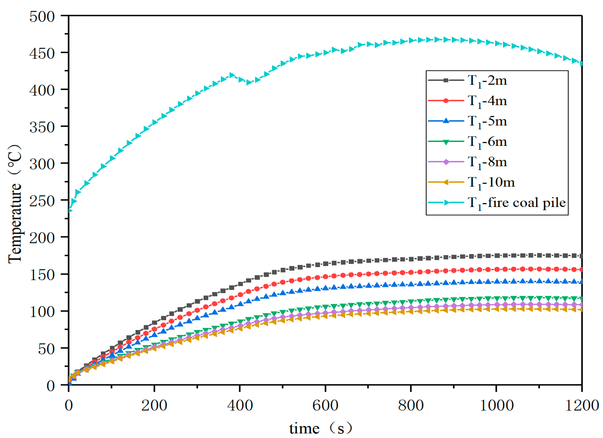
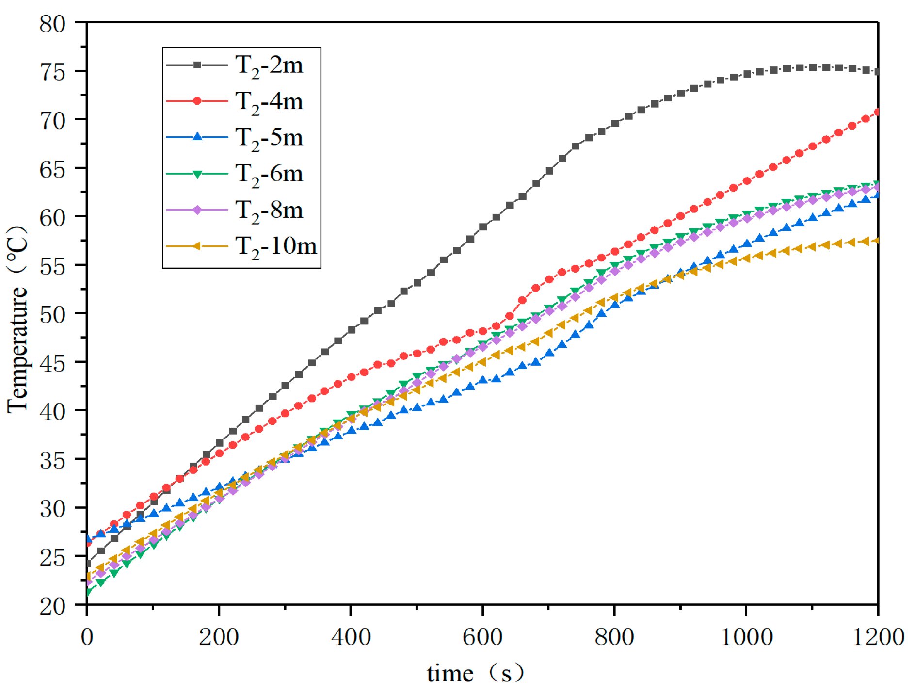
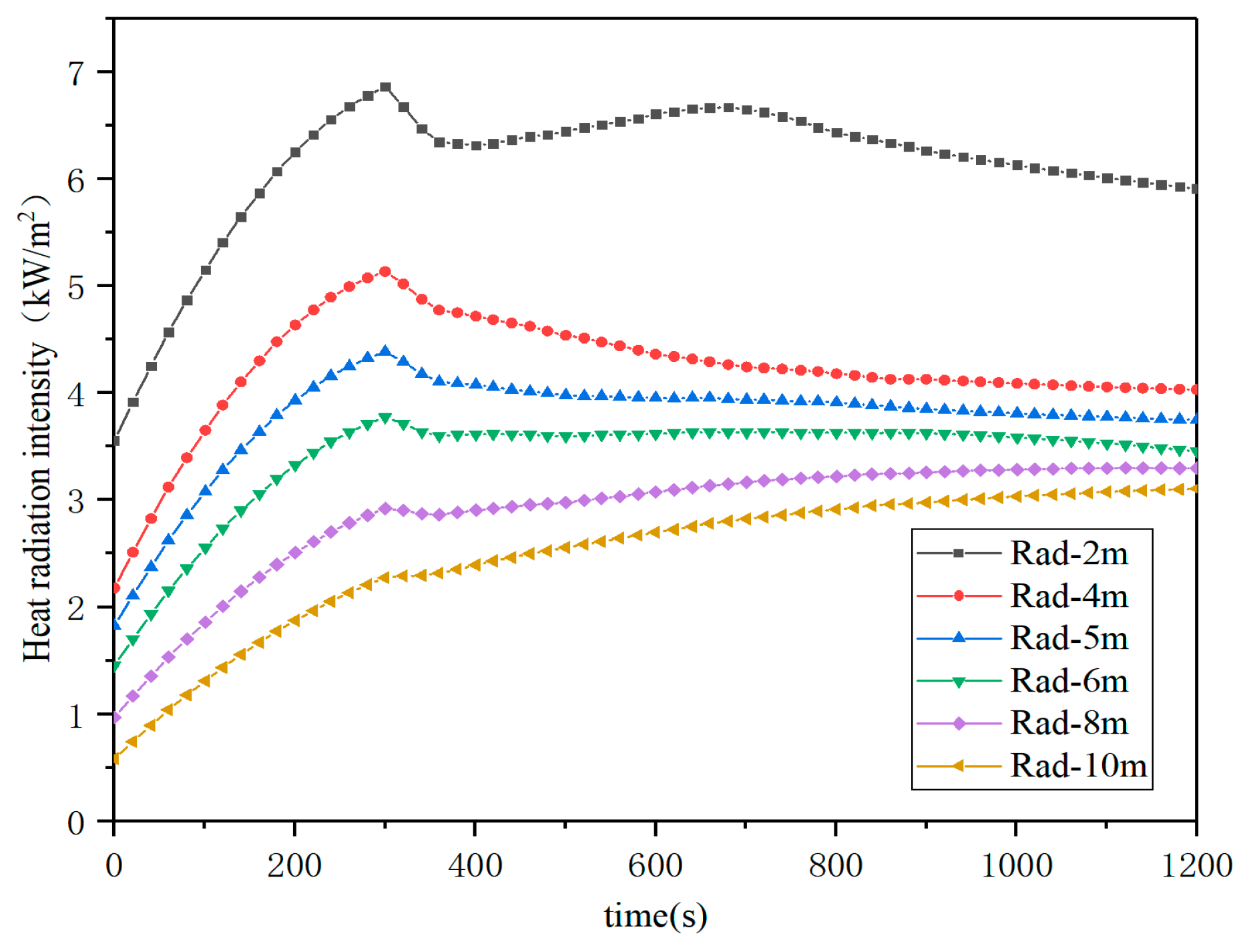
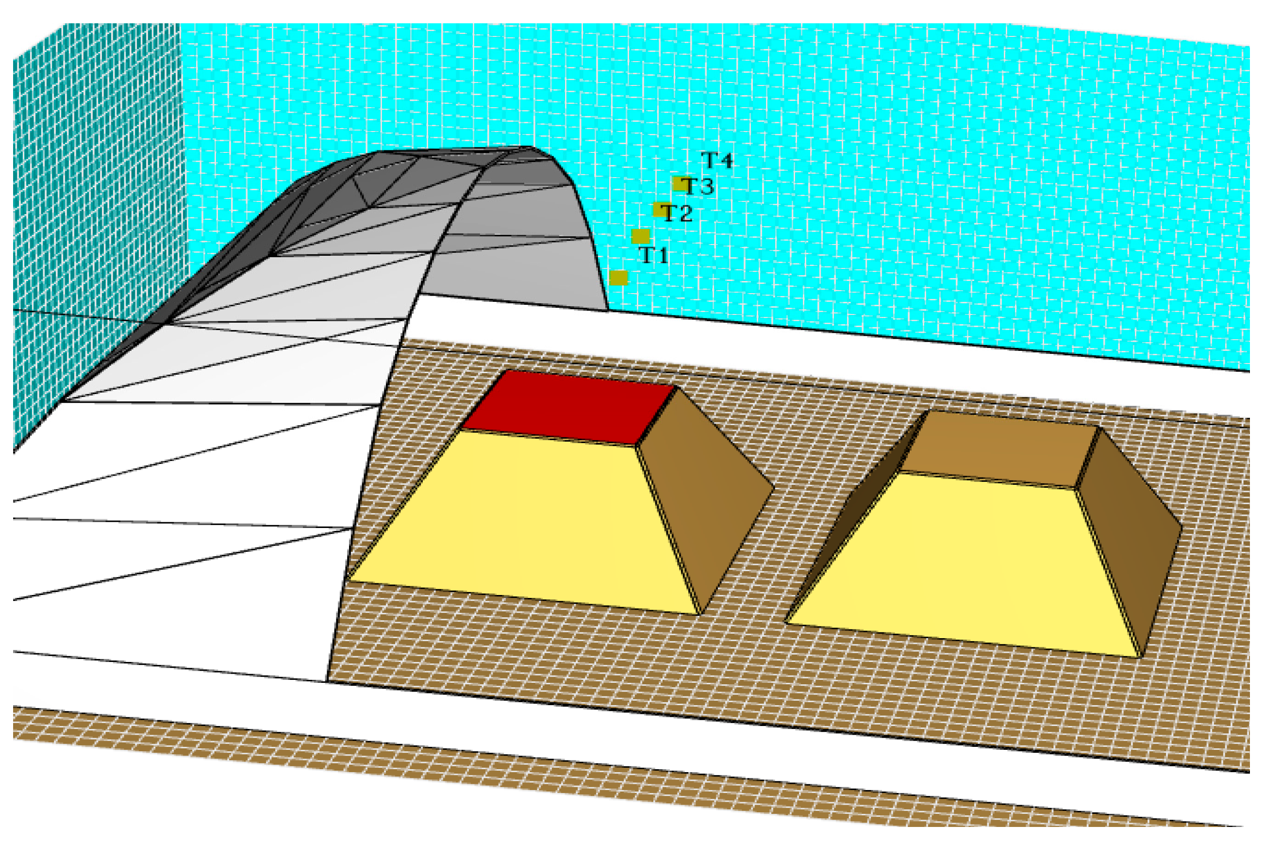
3.3.1. Influence of Fire Source Coal Pile–Coal Pile Spacing on Thermal Stability

The horizontal spacing is set to 2 m, 4 m, 5 m, 6 m, 8 m and 10 m, respectively, and the detection points are set near the fire source coal pile and adjacent coal pile. The following three types of detection points are monitored:
  • Temperature detection point T1 at the apex of adjacent coal pile
  • The adjacent coal pile base temperature detection point T2
  • The detection point R of the thermal radiation intensity received by the adjacent coal pile.
Figure 14 illustrates the thermal response of coal piles following fire ignition. The measurement point at the fire source exhibits a rapid temperature increase to 450 °C. For inter-pile distances below 5 m, the apex temperature T1 of adjacent coal piles rises significantly, stabilizing at 150 °C—exceeding the spontaneous combustion threshold and posing a substantial fire spread risk. In contrast, when the spacing is increased to more than 6 m, the peak T1 temperature remains below 100 °C, effectively preventing thermal radiation-induced ignition.
Figure 15 demonstrates that the temperature T2 of adjacent coal piles remained consistently below 100 °C across all tested distance, confirming no spontaneous combustion risk at these locations. These findings collectively indicate that a minimum separation distance of 6 m is critical for effective fire containment in coal storage configurations.
As shown in Figure 16, after the fire, the thermal radiation intensity received by the adjacent coal pile first rapidly rises to the peak, and then slowly decreases to the stable value. When the horizontal spacing is 2 m, the heat radiation intensity is the highest, about 7 kW/m2, which is lower than the critical value of 12.5 kW/m2. Therefore, when the fire occurs, the combustibles are more than 2 m apart, and the fire source coal pile will not ignite the adjacent coal pile.

3.3.2. Influence of Fire Source Coal Pile–Side Wall Spacing on Thermal Stability

The study evaluated four distinct separation distances (3 m, 4 m, 5 m and 6 m) between the ignition coal pile and the side wall. PVC membrane temperature monitoring points are strategically positioned as follows (Figure 17). In order to observe the detection points conveniently, the actual PVC membrane surface model is hidden:
  • Vertical PVC membrane surface temperature (T01-T03): the measured temperature distribution along the height of the air-supported membrane directly facing the ignition source;
  • Lateral wall PVC membrane surface temperature (T04-T06): we recorded the temperature of the side wall PVC membrane surface;
  • Radiometric measurements (R1-R2): R1: vertical thermal radiation intensity on the PVC membrane surface; R2: horizontal thermal radiation intensity on the side wall.
Figure 18a–d below show the temperature change diagram of the PVC membrane surface under different spacings. The figure shows that when the coal heap-to-side wall spacing is ≤5 m, the thermal plume rises rapidly to form a high temperature zone. T01-T03 data show that the maximum temperature is 260–280 °C, the supercritical pyrolysis temperature, and there is a risk of pyrolysis holes. When the spacing is 6 m, the maximum temperature drops to 180–200 °C, which is below the safety threshold, and the pyrolysis risk is reduced. Under the four spacing, the temperature of T04-T06 was stable at 60–85 °C, which did not reach the critical pyrolysis temperature and was considered safe.
As shown in Figure 19, the thermal radiation intensity in both vertical and horizontal directions showed an upward trend, but with the increase in the spacing, the thermal radiation intensity in the vertical direction gradually decreased. When the horizontal distance between coal pile and side wall is 3 m, the thermal radiation intensity received by the vertical PVC membrane surface reaches the maximum at about 450 s, with a peak value of 6 kW/m2, while the thermal radiation intensity received by the horizontal PVC membrane surface reaches the maximum at about 1200 s, with a peak value of only 2.5 kW/m2.

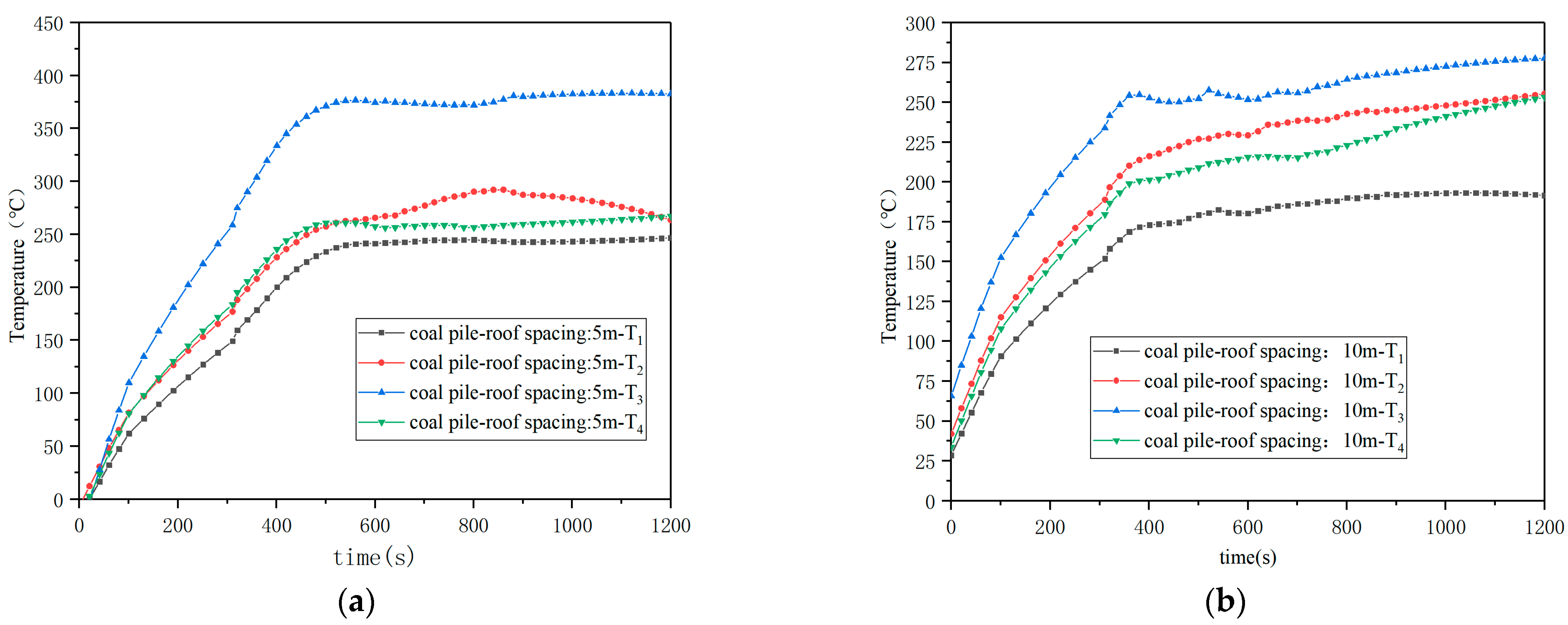
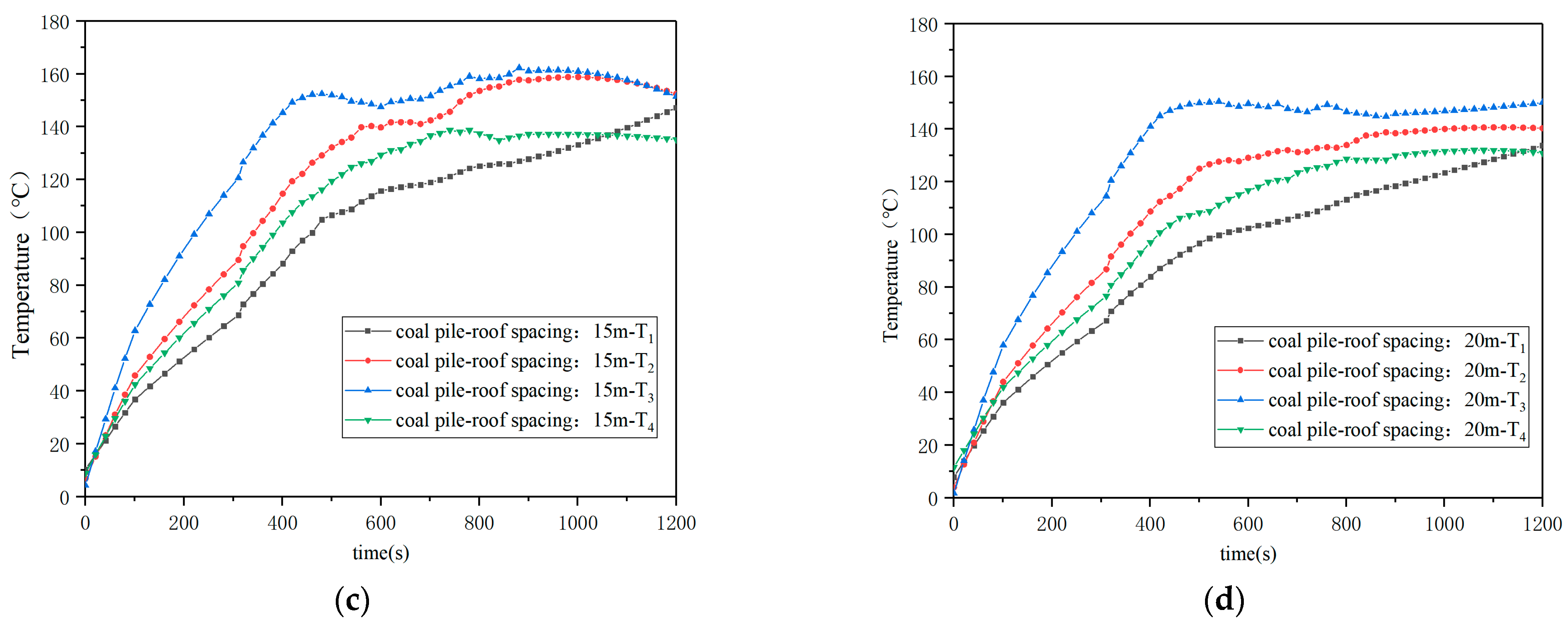
3.3.3. Influence of Fire Source Coal Pile–Roof Spacing on Thermal Stability

The results of the previous study show that the thermal radiation of the coal pile with the fire source is more significant in the vertical direction and weaker in the horizontal direction. By setting different spacing (5 m, 10 m, 15 m and 20 m) between the coal pile and the roof PVC membrane surface, the influence on the thermal stability of the ASMS coal storage bin is simulated. Detection points T1 to T4 are located in the ceiling, 5 m apart, and T3 is directly opposite the fire source. In order to observe the detection points conveniently, the actual PVC membrane surface model is hidden. Figure 20 shows the layout of the coal pile detection points.
Figure 21a–d are temperature change curves of the roof PVC membrane surface under different coal pile–roof spacing. After the fire occurs, the temperature of the roof PVC membrane surface increased rapidly. When the distance between the coal pile and the roof is 5 m, the temperature at the T3 point directly above the fire source reaches the highest, about 360 °C, and the temperature of other membrane surfaces is also stable at about 250 °C, which exceeds the critical pyrolysis temperature, and there is a significant risk of pyrolysis holes. When the distance between the coal pile and the roof is more than 10 m, the temperature of the roof membrane surface is stable at 140–160 °C under the working conditions of 15 m and 20 m, which is lower than the critical pyrolysis temperature and can be regarded as safe.
Figure 22 shows the variation law of thermal radiation intensity of the roof PVC membrane surface under different spacing. When the spacing is 5 m, the thermal radiation intensity received by the roof membrane surface is about 16.5 kW/m2, exceeding the critical thermal radiation intensity of 12.5 kW/m2, which will lead to the pyrolysis of the membrane material and will damage the stability of the building structure. However, when the spacing is ≥10 m, the received thermal radiation intensity is lower than the critical value. Therefore, for buildings storing combustible materials, in order to ensure the safety and stability of the building, the distance between the stacked combustibles and the ceiling membrane surface should not be less than 10 m.

4. Research Findings and Discussion

This study employs FDS simulations to systematically evaluate the structural stability of air-supported membrane structures (ASMS) coal storage bin, focusing on two critical aspects: (1) internal pressure stability under no-fire and fire conditions; (2) thermal stability under fire condition. The findings provide actionable insights for engineering design and risk mitigation.

4.1. Internal Pressure Stability Under No-Fire Condition

Under non-fire condition, the steady-state internal pressure of ASMS buildings is predominantly influenced by ambient temperature, leakage area and mechanical air supply volume. Notably, higher ambient temperatures correlate with reduced steady-state pressure magnitudes (e.g., a 10 K increase decreased pressure by 9.4 Pa), though the pressure stabilization time remains largely temperature-insensitive. This observation aligns with the thermodynamic principles which are reported in prior studies on pneumatic structures [23]: the higher the ambient temperature, the more intense the thermal motion of gas molecules, the larger the distance between gas molecules, the lower the density, and the lower the stable value of internal pressure.
Furthermore, our results further demonstrate that increasing the mechanical air supply volume not only shortens the pressure stabilization time but also elevates steady-state pressure values—a dual benefit not explicitly emphasized in earlier work [14,19]. Conversely, larger leakage areas accelerate pressure equilibration but compromise ultimate pressure stability, a trade-off that necessitates careful design optimization to balance energy efficiency and structural integrity.

4.2. Internal Pressure Stability Under Fire Condition

In fire scenarios, the ASMS coal storage bin’s internal pressure stability is governed by the heat release rate (HRR), fire location and fire growth type. The system’s internal pressure exhibits self-balancing behavior below 4 MW HRR, but values exceeding 10 MW HRR triggers dangerous pressure spikes (>600 Pa) capable of inducing structural deformation. While fire location has marginal effects on pressure dynamics (corner area fire shows the slowest pressure rise), fire growth type critically dictates fire behavior: slow-growth fires (e.g., t2-fire with α = 0.011 kW/s2) permit stable low-pressure states, whereas fast-growth fires (α ≥ 0.047 kW/s2) disrupt short-term stabilization.

4.3. Safety-Critical Design Parameters

Thermal stability analysis reveals that maintaining a minimum 6 m horizontal separation between ignition sources and adjacent coal piles effectively limits radiation intensity to below 12.5 kW/m2 and peak temperatures to under 100 °C, significantly mitigating spontaneous combustion risks. Similarly, a 6 m spacing from the side walls restricts PVC membrane surface temperatures to below 200 °C, preventing pyrolysis. However, when the vertical clearance to the roof PVC membrane surface is reduced to 10 m or less, radiation intensities reaches 16.5 kW/m2—exceeding critical material thresholds [24]. This directional anisotropy (vertical > horizontal radiation) underscores the need for asymmetric safety margins in design, a factor often overlooked in the previous literature [25].

4.4. Practical Implications and Limitations

The importance of studying the stability of air-supported membrane structure (ASMS) buildings is reflected in two aspects: the first is to ensure the stability of the structure and prevent the deformation or collapse caused by improper internal pressure; the second is to determine the safe protection distance of combustibles to effectively suppress the spread of fire.
The proposed safety protection spacing (more than 6 m horizontally and 10 m vertically) provides a practical framework for fuel storage. However, this study has the following problems:
  • This study did not use FEA tools to cross-validate pressure and thermal stress results.
  • Due to the lack of experiments, the “pressure change in the case of pressure exceeding the standard or holes in PVC membrane pyrolysis” is not deeply discussed.
  • In future work, probabilistic fire growth models should be added to quantify the uncertainty of different thresholds.
  • This study is discussed from the perspective of inhibiting fire spread and preventing smoke diffusion, without analyzing the smoke exhaust performance of the building and without considering the influence of membrane pyrolysis holes on internal pressure stability and thermal stability. Future work should deeply consider the material characteristics in real engineering and study the smoke exhaust performance of air-supported membrane structure buildings.

5. Conclusions

This study systematically investigates the internal pressure and thermal stability of ASMS coal storage bin under both non-fire and fire conditions using FDS simulations. The key findings are as follows:
  • Under non-fire conditions, ambient temperature, leakage area and mechanical air supply volume critically influence internal pressure stability, with higher temperatures reducing steady-state pressure (e.g., a 10 K increase decreases pressure by 9.4 Pa), while increased air supply improves both stabilization time and pressure magnitude.
  • Under fire conditions, internal pressure stability depends on heat release rate (HRR), fire location and fire growth type, with HRR > 10 MW causing dangerous pressure spikes (>600 Pa) and leading to structural deformation.
  • Thermal stability analysis identified the minimum safety protection spacing: a 6 m horizontal separation prevents coal pile spontaneous combustion (radiation < 12.5 kW/m2, temperature < 100 °C), while 10 m and above vertical spacing prevents PVC membrane pyrolysis (radiation < 12.5 kW/m2). These results provide actionable guidelines for ASMS fire protection design, emphasizing asymmetric safety margins due to vertical–horizontal radiation anisotropy.
Through numerical simulations, this study identifies key parameters significantly affecting the internal pressure stability of air-supported membrane structure buildings and proposes a safety protection spacing capable of effectively mitigating fire spread. The findings offer both theoretical insights and practical guidelines for the fire safety design of such engineered structures, with particular emphasis on smoke diffusion prevention.

Author Contributions

Conceptualization, Y.X. and Y.C.; methodology, Y.X.; software, N.L.; validation, Y.X., Y.C. and N.L.; formal analysis, N.L.; investigation, Y.X.; resources, Y.C. and N.L.; data curation, Y.X.; writing—original draft preparation, Y.X.; writing—review and editing, Y.C.; visualization, Y.X.; supervision, Y.C.; project administration, Y.C.; funding acquisition, Y.C. All authors have read and agreed to the published version of the manuscript.

Funding

This research was funded by Shanxi Provincial Science and Technology Cooperation and Exchange Programme, grant number 202304041101028.

Data Availability Statement

The data that support the findings of this study are available from the corresponding author upon reasonable request.

Acknowledgments

The authors are very grateful to the teachers for their help and the reviewers for their valuable comments and suggestions to improve the quality of this paper.

Conflicts of Interest

The authors declare no conflicts of interest.

References

  1. Liu, K. Research on Design and Construction of Tensioned Membrane Structures. Ph.D. Thesis, Harbin Institute of Technology, Harbin, China, 2007. [Google Scholar]
  2. Zhang, P.W. Analysis of the Fire Resistance of Rectangle-Plane Air-Supported Structure. Master’s Thesis, Xi’an University of Architecture and Technology: Xi’an, China, 2014. [Google Scholar]
  3. Jia, Y.W.; Guo, J.S.; Su, D.X. Numerical Fire Simulation of Rectangular Air-Supported Membrane Structure Based on Fluent; School of Civil Engineering, Beijing University of Technology: Beijing, China, 2018; pp. 448–456. [Google Scholar] [CrossRef]
  4. Zhang, H. Simulation of Fire Temperature Field for Large Space Air-Supported Membrane Structure. Master’s Thesis, Harbin Institute of Technology, Harbin, China, 2020. [Google Scholar] [CrossRef]
  5. Wang, Y.; Zhu, G.; Zhou, J.; Chai, G. Simulation research on evacuation of university gymnasium. Fire Sci. Technol. 2020, 39, 1215–1218. [Google Scholar]
  6. Dong, M.W.; Gu, Y.; Qiao, L.; Qu, H. Review on the structure of air-supported membranes. J. Build. Struct. 2023, 53, 544–550. [Google Scholar] [CrossRef]
  7. Stamatis, D.; Wainwright, E.R.; Lakshman, S.V.; Kessler, M.S.; Weihs, T.P. Finite Difference Analysis of Turbulent Combustion Dynamics in Large-Scale Fires. Combust. Flame 2020, 217, 93–102. [Google Scholar] [CrossRef]
  8. Han, D.-H.; Sung, H.-G. A numerical study on heterogeneous aluminum dust combustion including particle surface and gas-phase reaction. Combust. Flame 2019, 206, 112–122. [Google Scholar] [CrossRef]
  9. McGrattan, K. Fire Dynamics Simulator Technical Reference Guide: Version 6.7; National Institute of Standards and Technology: Gaithersburg, MD, USA, 2021. [Google Scholar] [CrossRef]
  10. Hurley, M.J.; Gottuk, D.; Hall, J.R.; Harada, K.; Kuligowski, E.; Puchovsky, M.; Torero, J.; Watts, J.M.; Wieczorek, C. SFPE Handbook of Fire Protection Engineering; Springer: Berlin/Heidelberg, Germany, 2016. [Google Scholar] [CrossRef]
  11. Du, P.; Ren, G.D.; Liu, Z.Y. Research on fire prevention performance of gas-borne membrane structure coal storage shed based on physical test and FDS simulation. Build. Sci. 2024, 40, 84–92. [Google Scholar]
  12. Guo, F. Study on Burning Behavior of Textile Membrane and Overall Stability Analysis of Air-Supported Membrane Structure Under Fire Condition. Master’s Thesis, China University of Mining and Technology, Xuzhou, China, 2016. [Google Scholar]
  13. Wang, G.L. Numerical Simulation of Internal Pressure Got Air-Supported Membrane Structure Under FIRE based on Abaqus; Harbin Institute of Technology: Harbin, China, 2023. [Google Scholar] [CrossRef]
  14. Yan, F. Study on Fire Response and Collapse Mechanism of Air-Supported Structure. Ph.D. Thesis, Beijing University of Technology, Beijing, China, 2022. [Google Scholar] [CrossRef]
  15. GB55037-2022; Code for Fire Prevention in Building Design. Ministry of Housing and Urban-Rural Development of the People’s Republic of China: Beijing: China, 2022.
  16. Ding, H.; Xu, Y.D.; Deng, Q.L.; Lian, Z.X. Simulation study on influence of fire smoke flow on evacuation in high-rise buildings. China Saf. Sci. J. 2020, 30, 118–124. [Google Scholar] [CrossRef]
  17. Chen, Q.Y.; Wang, Y.S.; Su, J. Single Particle Ignition of Different Rank Coals. J. Eng. Thermophys. 2020, 41, 2052–2058. [Google Scholar]
  18. Li, L.; Zhang, R.W.; Pei, X.D. Analysis on Indication Gases of Different Coal’s Oxidized Spontaneous Combustion. Min. Saf. Environ. Prot. 2006, 5, 69–71, 89. [Google Scholar]
  19. Zhang, L.; Zhu, G.Q.; Zhang, G.W.; Han, R.S. Performance-based Fire Design of Air-supported Membrane Coal Storage Shed. Proc. Eng. 2013, 52, 593–601. [Google Scholar] [CrossRef]
  20. Bahramian, A. The effect of thermal and non-thermal routes on treatment of the Mg–Al layered double hydroxide catalyst dispersed by titania nanoparticles in products distribution arising from poly(ethylene terephthalate) degradation. Polym. Degrad. Stab. 2020, 179, 109243. [Google Scholar] [CrossRef]
  21. EN 13782:2015; Temporary Structures—Tents—Safety. European Committee for Standardization (CEN): Brussels, Belgium, 2015.
  22. Li, N.; Lu, W.Y. Applied Research of the calculation parameters for natural smoke exhaust. Tianjin Constr. Sci. Technol. 2022, 32, 50–53. [Google Scholar]
  23. Yu, Y.; Cao, Z.G.; Sun, Y.; Wu, Y. FDS simulation of internal pressure of air-supported membrane structure under fire. J. Northeast. Univ. (Nat. Sci.) 2022, 43, 1176–1182. [Google Scholar]
  24. Zhang, Y. Simulation study on fire temperature and internal air pressure of air-supported membrane structure coal storage shed. Fire Sci. Technol. 2024, 43, 492–497. [Google Scholar] [CrossRef]
  25. Duan, P.J. Simulation Study on Smoke Spreading Law of Long-Span Warehouse Fire. Master’s Thesis, Xi’an University of Science And Technology, Xi’an, China, 2020. [Google Scholar] [CrossRef]
Figure 1. Field diagram of air-supported membrane coal storage bin. (a) shows the site map of the coal storage bin when there is no storage; (b) Site map of the coal storage bin when a small amount of material is stored.
Buildings 15 01734 g001
Figure 2. Numerical model of fire in air-supported membrane coal storage bin.
Buildings 15 01734 g002
Figure 3. Coal storage bin fan site map.
Buildings 15 01734 g003
Figure 4. (a) Internal pressure and comparison diagram in no-fire condition; (b) comparison diagram of internal pressure under fire condition.
Buildings 15 01734 g004
Figure 5. Internal pressure curves at different ambient temperatures.
Buildings 15 01734 g005
Figure 6. Internal pressure variation curve under different air supply volumes.
Buildings 15 01734 g006
Figure 7. Internal pressure variation curves under different leakage areas.
Buildings 15 01734 g007
Figure 8. Fire source area division diagram.
Buildings 15 01734 g008
Figure 9. Influence of fire power on building internal pressure.
Buildings 15 01734 g009
Figure 10. Effect of fire growth coefficient on internal pressure.
Buildings 15 01734 g010
Figure 11. Influence of fire source position on internal pressure.
Buildings 15 01734 g011
Figure 12. Model of ASMS coal storage bin.
Buildings 15 01734 g012
Figure 13. Schematic diagram of detection points between coal piles.
Buildings 15 01734 g013
Figure 14. Temperature T1 at top of adjacent coal piles at different distances.
Buildings 15 01734 g014
Figure 15. Temperature T2 at the bottom of adjacent coal piles at different distances.
Buildings 15 01734 g015
Figure 16. Thermal radiation intensity of adjacent coal piles under different coal pile distances.
Buildings 15 01734 g016
Figure 17. Layout of fire source coal pile detection points.
Buildings 15 01734 g017
Figure 18. (a) Membrane surface temperature at 5 m distance between coal pile and side wall; (b) distance is 4 m (c) distance is 5 m; (d) distance is 6 m.
Buildings 15 01734 g018
Figure 19. Side wall heat radiation intensity under different side wall distances.
Buildings 15 01734 g019
Figure 20. Layout of coal pile detection points.
Buildings 15 01734 g020
Figure 21. (a) PVC membrane surface temperature at 5 m spacing between coal pile and ceiling; (b) spacing is 10 m; (c) spacing is 15 m; (d) spacing is 20 m.
Buildings 15 01734 g021aBuildings 15 01734 g021b
Figure 22. Roof PVC membrane heat radiation intensity under different distances.
Buildings 15 01734 g022
Table 1. Validation of grid independence.
Gird (m)Temperature (°C)Relative Error (%)
2.057.54-
1.065.2413.38
0.7568.284.65
0.573.447.5
0.274.71.7
0.175.481.0
Table 2. List of conditions without fire.
Leak Area (m2)Supply Volume (m3/s)Ambient Temperature (K)
0.24263
0.24273
0.24283
0.24293
0.24303
0.24313
0.21293
0.22293
0.23293
0.24293
0.25293
0.26293
0.27293
0.28293
0.064293
0.084293
0.14293
0.24293
0.34293
0.44293
Table 3. List of fire conditions.
Fire PositionHRR (MW)Fire Growth Factor (kW/s2)
1 area2.50.044
2 area2.50.044
3 area2.50.044
Wall-side area2.50.044
Corner area2.50.044
3 area1.50.044
3 area30.044
3 area40.044
3 area100.044
3 area200.044
3 area2.50.00278
3 area2.50.011
3 area2.50.178
Table 4. List of research conditions for thermal stability of membrane.
TypeWorking ConditionDistance (m)
Coal pile–Coal pile12
24
35
46
58
610
Coal pile–Side wall membrane surface73
84
95
106
Coal pile–Roof membrane surface115
1210
1315
1420
Disclaimer/Publisher’s Note: The statements, opinions and data contained in all publications are solely those of the individual author(s) and contributor(s) and not of MDPI and/or the editor(s). MDPI and/or the editor(s) disclaim responsibility for any injury to people or property resulting from any ideas, methods, instructions or products referred to in the content.

