Abstract
Light steel keel fireproof exterior walls are one of the new composite walls that have been widely used in recent years. This paper analyzes the factors affecting the displacements of the connectors and wall panels and modifies the corresponding displacement model. ABAQUS was used to establish the simulation analysis of the L-shaped and special-shaped steel angle component, and the results were compared with the experimental model to verify the rationality. The effect of vertical keel spacing and layout, the number of special-shaped steel angles, the L-shaped steel angle thickness, and the number of self-tapping screws for L-shaped steel angles to steel beams were explored based on the validated finite element model. The calculation model was modified based on the results of the simulation. The results showed that the simulation results fit well with the experimental results, which verified the reliability of the finite element model. The number of connectors and the number of self-tapping screws are the main factors affecting the special-shaped and L-shaped steel angle components, respectively. By modifying the rotation constraint factor of the L-shaped steel angle and adding a discount factor for the wall panel, the accuracy of the associated displacement calculation model could be improved.
1. Introduction
Assembled steel structure systems have good economic and environmental benefits, and their main advantages include a high degree of assembly, a light weight, and good seismic performance [1,2,3,4]. The assembled steel structure’s exterior maintenance walls can be categorized into masonry infill walls, single material walls, and composite walls according to the material. Among these, the composite wall is assembled by two or more materials; it is more environmentally friendly, has a higher degree of assembly, and the construction process is quite simple [5,6]. The light weight and high strength of the light steel keel makes it a better match for fireproofing materials, and light steel keel composite walls have recently been widely used. Common fireproofing materials include gypsum, calcium silicate, and phenolic fibers, and all of these materials have fire-resistant and heat-insulating properties. In fire scenarios, the light steel keel can still be in a relatively normal working environment and keep its load-bearing capacity [7,8].
To ensure that different materials can work well with the main body of the steel structure, a large number of studies have been carried out on the performance of the connection between the steel frame and the enclosing wall [9,10,11,12,13,14]. Stability is the first factor to be considered when connecting the wall to the steel structure. In addition, the connectors should be easy to install and should not be too costly. Geng et al. proposed an external connection scheme to enhance the assembly of the light steel keel wall and verified its reliability under normal use conditions versus seismic conditions [15]. Tang et al. proposed a new filled-bolt connection, which exhibited satisfactory mechanical properties [16]. Steel angles have been proven to play an important role in connecting steel frames to enclosing walls [17]. This study focused on two types of connections, L-shaped and special-shaped steel angles, and explored the effects of the spacing and layout of vertical keels, the number of special-shaped steel angle connectors, the thickness of L-shaped steel angles, and the number of self-tapping screws used to connect the enclosing wall to the steel beams. This study could provide a useful reference for the selection and layout of the light steel keel walls and connections.
Displacement under external loading conditions is a visual reflection of the performance of the walls. Wind load is one of the most important factors affecting the out-of-plane displacement of walls, especially for high buildings. Under the influence of strong winds, there is a risk of partial or complete overturning of the walls, which would seriously threaten the safety of life and property [18]. On the other hand, in earthquake-prone regions, the impact of seismic forces on walls cannot be ignored. Without a reasonable seismic design, a large number of buildings would crack and collapse during earthquakes [19]. To reduce the risk of wall instability, a lot of structural displacement monitoring methods have been developed. Current methods are mainly divided into two categories: one is the displacement monitoring technology based on sensors, and the other is based on vision, and both can provide insight into the displacement of a wall over a period of time [20]. Obviously, it is much more valuable to study the prediction of the displacement of the wall before construction is carried out. Experiments and numerical simulations are currently the main methods used to predict the displacement of light steel keel walls and connections [21,22,23,24,25,26]. Telue et al. investigated the force properties of walls under axial loads by conducting a large number of experiments [27]. Tian et al. explored the effects of wall panel type, screw spacing, and load type on wall performance based on experiments [28]. Wu et al. developed a refined model of light steel keel composite walls and verified the accuracy of the model through experiments [25]. Compared to experimental methods, numerical simulation is a much more efficient method. Finite element analysis (FEA) is currently the most widely used numerical simulation approach, but for some complex structures, finite element simulation is still a time-consuming process, and the accuracy is difficult to guarantee. Overall, experimental and simulation analyses usually consume a lot of economic and time costs, so it is necessary to propose an accurate and reliable theoretical calculation model. In this paper, based on previous studies, more accurate displacement calculation models for walls and connectors are proposed.
To summarize, this paper focused on two connection forms of special-shaped and L-shaped steel angles. Various displacement influence factors were analyzed, and more accurate displacement calculation models were proposed. The research in this paper can provide an important reference for the layout of light steel keel walls and connectors. More accurate theoretical calculation models can provide a more efficient option for the displacement analysis of walls and connections.
2. Materials and Methods
2.1. Finite Element Modeling and Validation
- (1)
- Modelling of geometry
The FEA process was based on the ABAQUS 2023 software. Firstly, the geometry was modeled based on common light steel keel exterior wall characteristics. The dimensions and material composition of the wall are shown in Figure 1. The width of the wall panel is 1200 mm, and the length is 3110 mm. The size of the C-type light steel keel in the wall panel is h × b × c × t = 89 mm × 41 mm × 8 mm × 0.8 mm, where h, b, c and t are the cross-section height of the steel keel, the width of the flange, the width of the rolled edge, and the thickness, respectively, and the spacing of the C-type steel keel, d, is 240 mm. The dimensions of the phenolic fire prevention board and magnesium chloride gypsum board are both l × b × t = 3110 mm × 1200 mm × 4 mm, where l, b and t are the length, width and thickness, respectively. To study the out-of-plane displacements of the wall under different connections, two connection methods were designed: one through-length L-shaped steel angle connection for QB1 (Figure 2) and one special-shaped steel angle connection for QB2 (Figure 3). Steel angles, wall panels and steel beams were connected to each other with self-tapping screws. The steel beam cross-section dimensions are 150 mm × 150 mm × 8 mm × 8 mm. Finally, a geometric model was built, as shown in Figure 4.
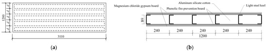
Figure 1.
The dimensions and material composition of the wall: (a) plan schematic; (b) section schematic.

Figure 2.
Schematic diagrams: (a) L-shaped steel angle and screw holes; (b) L-shaped steel angle connection; and (c) L-shaped steel angle cross-section and screw hole locations (units: mm).
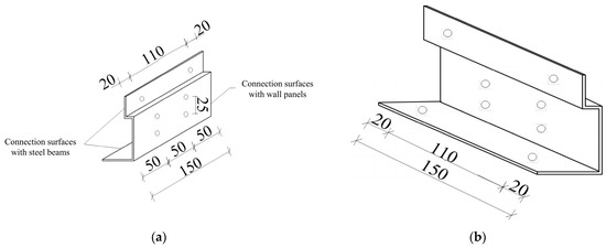
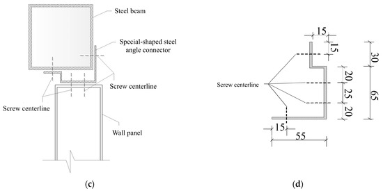
Figure 3.
The schematic diagrams: (a) outer face of the special-shaped steel angle; (b) inside face of the special-shaped steel angle; (c) special-shaped steel angle connection; (d) special-shaped steel angle cross-section and screw hole locations (units: mm).

Figure 4.
Finite element geometric model: (a) overall model; (b) QB1 connection model; (c) QB2 connection model.
- (2)
- Material properties
The keel of light steel keel fireproof exterior wall is made of cold-formed thin-walled steel, covered with phenolic fire prevention board and magnesium chloride gypsum board, and filled with aluminum silicate cotton inside. The materials of steel beams and steel angle connectors are Q235 ordinary carbon steel and Q345 ordinary carbon steel, respectively. The cold-formed thin-walled steel, Q235 ordinary carbon steel, and Q345 ordinary carbon steel are regarded as elastic–plastic materials. The phenolic fire-prevention board and magnesium chloride gypsum board were considered as elastic material. The parameters of the elastic and plastic stages of the elastic–plastic material during the simulation are shown in Table 1 and Table 2, respectively. It should be noted that isotropic hardening of the materials in the plastic stage was also considered. For elastic materials, when the external load exceeds their strength, the material will fracture and stop working. The relevant parameters are presented in Table 3.

Table 1.
Elastic–plastic material parameters at the elastic stage.
Table 2.
Elastic–plastic material parameters at the plastic stage.
Table 3.
Elastic material parameters.
- (3)
- Unit type and mesh size selection
For the light steel keel, phenolic fire prevention board, and magnesium chloride gypsum board, the S4R unit was applied. The S4R unit can be used for modeling thin or thick shell structures with reduced integration. It includes hourglass mode control and allows for finite film strains. For the L-shaped and special-shaped steel angle and the steel beams, the unit type is C3D8R. The C3D8R unit is less prone to shear self-locking under bending loads and has advantages in solving displacement problems. In addition, by using C3D8R units, the accuracy of the analysis would rarely be affected when there is a twisting deformation of the meshes.
The determination of mesh size Is an Important step In FEA. In general, the smaller the mesh size, the more accurate the simulation results. However, smaller mesh sizes also consume longer computation time, so reaching a balance between accuracy and computational cost is a difficult subject. With reference to previous studies [29], the choice of mesh size could be related to the surface area of the component, and the following equations are given:
Coarse mesh size = 0.049 (Overall surface area of the component)1/2
Fine mesh size = 0.0245 (Overall surface area of the component)1/2
Finally, based on the results of the formulas, the mesh size of the light steel keel and the connectors was taken as 10 mm. For the phenolic fire protection board and steel frame, the mesh size was taken as 50 mm.
- (4)
- Interactions and constraints
Tie binding constraints were defined between the horizontal and vertical keels to form the keel frame. In addition, Tie binding constraints were also defined between the keel frame, phenolic fire prevention board, and magnesium chloride gypsum board. After determining the position of the self-tapping screws, the tie-binding constraints were defined again. The peripheral units at the self-tapping screws were coupled by shifts while setting up contact between the steel angle and the steel demand and wall panels in the form of normal hard contact with tangential friction. In addition, fixed constraints were applied at 4 corners on the steel beams, and the model as a whole could be vertically displaced (Figure 5).
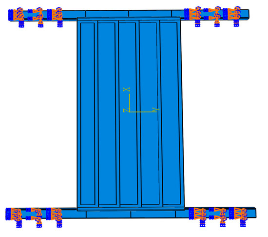
Figure 5.
Schematic diagram of the constraint.
- (5)
- Loading procedure
In this paper, to simulate wind loads, a graded loading procedure was set up with a load of 0.402 kN/m2 per level. A total of eight levels of loadings (maximum of 3.216 kN/m2) were used for the L-shaped steel angle component. Ten levels of loadings (maximum of 4.020 kN/m2) were used for the special-shaped steel angle component.
- (6)
- Validation
Taking into account the above geometrical models, material properties, connection methods, etc., the corresponding experimental models were developed to verify the validity of the FEA models (Figure 6). The loading procedure was realized by static stacking 10 kg gravel bags. Fifteen bags per level were required, evenly spread, keeping 20 mm spacing between bags and bags, to prevent the sandbags from the force of accumulation of arching. Three displacement gauges were arranged at the mid-span of the wall panel and at the L-shaped steel angle connection (or special-shaped angle connection) separately to measure the settlement of the wall panel and the connectors.

Figure 6.
Schematic diagrams: (a) experimental setup; (b) loading process.
2.2. Simulation Scheme
To analyze the effects of different factors on the displacements of wall panels and connections under loading conditions, the simulation scheme shown in Table 4 was proposed. The special-shaped angle connection components mainly considered the number of connectors, the keel layout, and the keel spacing. The L-shaped angle connection components mainly considered the steel angle thickness, the keel layout, the keel spacing, and the number of self-tapping screws used in connection with steel beams. The symmetrical layout is symmetrical in the direction of the keel opening, as shown in Figure 7.
Table 4.
The simulation scheme.

Figure 7.
The diagram of the symmetrical keel layout.
2.3. Displacement Calculation Model
Due to the complex structure of steel angle connectors and light steel keel walls, there is no recognized accurate displacement calculation model [30]. Based on the structural mechanics and previous research, the following preliminary calculation model for the displacements of special-shaped steel angle connectors, L-shaped steel angle connectors, and wall panels at mid-span was given below [31,32,33]. Subsequently, more accurate models would be revised based on multiple sets of numerical simulations.
- (1)
- Displacement calculation model for L-shaped steel angle connectors
The calculation sketch of the L-shaped steel angle is shown in Figure 8, and the displacements of the connectors under out-of-plane loading can be calculated according to the following formulas:
where wk is the load value; b is the wall plate section width; l0 is the calculated span of the wall panel; ka is the rotation constraint coefficient of the L-shaped steel angle connectors; nt is the number of screws connecting L-shaped steel angle connectors to steel beams; ta is the thickness of the L-shaped steel angle connectors; D0 is the lateral displacement stiffness of c with the stiffness as the value of the external force required to cause a unit deformation of an object; E is the modulus of elasticity of the connectors; I is the moment of inertia of the connectors; and c is the distance from the center of the steel beam connecting screws to the line of shear effect.

Figure 8.
Schematic diagrams: (a) L-shaped steel angle connection; (b) calculation of forces.
- (2)
- Displacement calculation model for the special-shaped steel angle connectors
The calculation sketch of the special-shaped steel angle is shown in Figure 9, and the displacements of connectors under out-of-plane loading can be calculated according to the following formulas:
where wk is the load value; b is the wall panel section width; l0 is the calculated span of the wall panel; Kb is the overall rotation constraint coefficient of the special-shaped steel angle connectors; D0 is lateral displacement stiffness of AB; N is the number of the connectors; kb is the rotation constraint coefficient of a single special-shaped steel angle connector; n1 is the number of extraction-resistant screws; n2 is the number of shear-resistant screws; and tb is the thickness of the special-shaped steel angle connectors.

Figure 9.
Schematic diagrams: (a) special-shaped steel angle connection; (b) calculation of forces.
- (3)
- Displacement calculation model for the wall panel
The displacement of the wall panel under out-of-plane loading can be calculated according to the following formulas:
where wk is the load value; b is the wall plate section width; l0 is the calculated span of the wall panel; Bs is the combined stiffness of the wall panel; Es is the modulus of elasticity of the light steel keel; Is the sum of the moments of inertia of the keel; m is the mask combination effect coefficient; and I’1 is the moment of the inertia of the phenolic panels.
3. Results
3.1. Comparison of Simulation and Experimental Results
Table 5 shows the experimental results and simulation results of the two experimental components under certain loading conditions. The load–displacement curves of the wall panels and the connectors are shown in Figure 10. As can be seen from the figure, the curves obtained from FEA and experiments are basically consistent. According to the FEA results, the displacements of the components increased linearly with the load, indicating that the components were all in an elastic state. In contrast, although the experimental results have similar trends, the loading–displacement process is significantly more complex. The simulation inaccuracy of the curves of QB1 is smaller than that of QB2, and the inaccuracies between the experimental results and the FEA results are all within 20%. The FEA values are smaller than the experimental values, which might be due to the fact that FEA ignored the slip between the phenolic panels and the light steel keel, which increased the stiffness of the wall panels.
Table 5.
Experimental and FEA values of the displacements for the components.

Figure 10.
Load–displacement curves: (a) the connectors for QB1; (b) the connectors for QB2; (c) the wall panel for QB1; and (d) the wall panel for QB2.
3.2. Analysis of Displacement Influencing Factors
3.2.1. L-Shaped Steel Angle Connectors and Wall Panels
- (1)
- Keel spacing
The load–displacement curves for the LA group are shown in Figure 11. The wall panel displacement under the same load decreased with the decreasing keel spacing, indicating that decreasing the keel spacing could improve the out-of-plane stiffness of the wall panel to some extent, but the effect is not obvious. The load–displacement curves of the connectors basically coincide, indicating that reducing the keel spacing has no effect on the stiffness of the connectors.
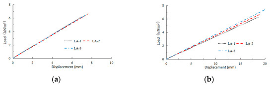
Figure 11.
Load–displacement curves for the LA group: (a) the L-shaped steel angle connectors; and (b) the wall panel.
- (2)
- Thickness of the L-shaped steel angles
The load–displacement curves for the LB group are shown in Figure 12. The displacements of the wall panel and the L-shaped steel angle connectors under the same load decreased with the increasing thickness of the connectors, indicating that the thicker the thickness of the connection, the higher the stiffnesses of the wall panel and the connectors. When the thickness of the connectors increased from 1.5 mm to 2 mm, the effect on the stiffness of the wall panels and connectors was greater than when the thickness increased from 2 mm to 2.5 mm.

Figure 12.
Load–displacement curves for the LB group: (a) the L-shaped steel angle connectors; and (b) the wall panel.
- (3)
- Number of screws connecting the connector to the steel beams
The load–displacement curves for the LC group are shown in Figure 13. The displacement of the wall panel and the L-shaped steel angle connectors under the same load decreased with the increasing number of screws connecting the connector to the steel beams, indicating that the more screws used, the higher the stiffness of the wall panel and the connectors. When the number of screws increased from 3 to 4, the effect on the stiffness of the wall panels and connectors was greater than when the number of screws increased from 4 to 5.

Figure 13.
Load–displacement curves for the LC group: (a) the L-shaped steel angle connectors; (b) the wall panel.
- (4)
- Layout of the keel
Comparing LA-2 and LB-3, the load–displacement curves of the wall panels and connectors basically coincided, so changing the keel layout has no significant effect on the stiffness of the wall panels and connectors.
3.2.2. Special-Shaped Connectors and Wall Panels
- (1)
- Keel spacing
The load–displacement curves for the YA group are shown in Figure 14. The wall panel displacement under the same load decreased with the decreasing keel spacing, indicating that decreasing the keel spacing could improve the out-of-plane stiffness of the wall panel to some extent, but the effect is not obvious. The load–displacement curves of the connectors basically coincide, indicating that reducing the keel spacing has no effect on the stiffness of the connectors.

Figure 14.
Load–displacement curves for the YA group: (a) the special-shaped steel angle connectors; and (b) the wall panel.
- (2)
- Number of special-shaped steel angle connectors
The load–displacement curves for the YB group are shown in Figure 15. The displacements of the wall panel and the special-shaped steel angle connectors under the same load decreased with the increasing number of the special-shaped steel angle connectors, indicating that the more connectors used, the higher the stiffness of the wall panel and the connectors. When the number of connectors increased from two to tree, the effect on the stiffness of the wall panels and connectors was greater than when the number of connectors increased from three to four.

Figure 15.
Load–displacement curves for the YB group: (a) the special-shaped steel angle connectors; and (b) the wall panel.
- (3)
- Layout of the keel
Comparing YA-2 and YB-3, the load–displacement curves of the wall panels and connectors basically coincided, so changing the keel layout has no significant effect on the stiffness of the wall panels and connectors.
3.3. Displacement Model Modification
3.3.1. Displacement Model Modification for Connectors
The rotation constraint coefficients and displacements obtained from the pre-prepared displacement calculation model are listed in Table 6 along with the simulated values. The results show that the theoretically calculated values were in good agreement with the simulation values, except for LC-2 and LC-3. The theoretical calculations for LC-2 and LC-3 are on the small side, which may be due to the fact that Equation (5) overestimated the contribution of the number of screws to the stiffness of the connectors.
Table 6.
The calculated and simulated values of the connector displacements.
Substituting the simulation values of the displacement of the connectors of the LC group into Equation (5), the rotation constraint coefficient kα values of LC-1, LC-2, and LC-3 were inverted to 0.181, 0.232, and 0.281, respectively. Combining the rotation constraint coefficients obtained from theoretical calculations of the LA and LB groups of the connectors, kα was modified as follows:
The ka values and the corresponding displacements were recalculated based on the modified equations and compared with the simulated values. The results are shown in Table 7. The results showed that the recalculated values are all within the 10% inaccuracy, indicating the accuracy of the modified displacement model.
Table 7.
The recalculated and simulated values of the connector displacements.
3.3.2. Displacement Model Modification for Wall Panels
The combined stiffness of the wall panel and displacement obtained from the pre-prepared displacement calculation model are listed in Table 8 along with the simulated values. As shown in the table, the theoretically calculated values of wall panel displacements are generally larger than the simulated values, which may be due to the assumption of ideal articulated constraints between the wall panels and the connectors in the calculations, whereas the screws between the wall panels and the connectors in the numerical analyses could provide the rotational constraints at the panel ends and the setup of contacts between the transverse keel at the end of the wall panel and the connectors limited the rotational displacements at the end of the panels so that the theoretical results of the calculations are on the large side.
Table 8.
The calculated and simulated values of the wall panel displacements.
A discount factor γ is introduced to discount the values calculated by the theoretical formula:
Substituting the simulation values of the wall panel displacement to fit γ, the final γ was determined to be 0.71.
The displacements were recalculated based on the modified equations and compared with the simulated values. The results were shown in Table 9. The results showed that the recalculated values are all within 10% inaccuracy, indicating the accuracy of the modified displacement model.
Table 9.
The recalculated and simulated values of the wall panel displacements.
4. Discussion
4.1. Analysis of Factors Affecting the Displacements of Connectors and Wall Panels
Light steel keel fireproof exterior walls are one of the main types of current assembled structural walls. The connection performance of the wall and the steel frame directly determines the effect of the wall and the main structure of the building working together. Heimbs et al. compared the effects of different forms of L-shaped steel angle nodes and bolted nodes and analyzed the corresponding damage modes [17]. Zhang et al. designed a novel connection using a U-shaped connector to connect the wall to the steel frame, which was shown to have good performance [34]. The performance of the connection between the wall and the steel frame is determined by multiple factors [35]. A systematic analysis of the multiple influence factors on the performance of wall and steel beam connections can provide an important reference for the selection and placement of connectors and wall panels. This paper focused on two types of connections, including L-shaped steel angles and special-shaped steel angles. For the L-shaped steel angles, the spacing and arrangement of the keels, the thickness of the L-shaped steel angles, and the number of screws connecting the L-shaped steel angles to the steel beams were considered. For the special-shaped steel angles, the spacing and arrangement of the keels and the number of connectors were taken into account. The displacements of the connection and wall panels under loading conditions were regarded as the evaluation index of the performance of the connections. The results showed that the number of screws connecting the L-shaped steel angles to the steel beams and the number of special-shaped steel angle connectors are decisive factors in improving the performance of the connection between the wall and the steel frame. However, when the number of screws and connectors reached some thresholds, the performance enhancement will no longer be evident.
4.2. Modification of the Displacement Model for Connectors and Wall Panels
The keel in the light steel keel fireproof exterior wall is generally rolled from 0.5 mm–1.5 mm galvanized coils, and the thin thickness and complex structure make the theoretical calculation difficult. At present, most studies on the connection between light steel keel fireproof exterior walls and steel frames are based on experiments and finite element simulation analysis [36]. However, compared to experiments and finite element simulations, theoretical calculation is a method that can be applied and generalized more easily. In this paper, on the basis of the previous research and the theory of structural mechanics, the corresponding displacement calculation models were pre-proposed for L-shaped steel angle connectors, special-shaped steel angle connectors and wall panels. The computational results of these models were then compared with the simulation results, and further modifications were made. The results showed that the pre-proposed displacement model for L-shaped steel angle connectors overestimated the contribution of screws to the rotational stiffness; the rotation constraint coefficient was therefore modified. The ideal articulation constraints assumed by the pre-proposed wall panel displacement model would bias the calculations, and a discount factor was added accordingly. The computational results of the modified model were all in good agreement with the simulation results, indicating that the modified model can provide a fast and accurate new approach for obtaining the displacements of connectors and wall panels.
4.3. Limitations
The present study focused on two connection forms of special-shaped and L-shaped steel angles, different displacement effect factors were investigated and more accurate displacement calculation models were introduced. For further promotion of the light steel keel exterior walls, there are still some limitations that need to be addressed. Compared to traditional walls, light steel keel exterior walls usually have a higher cost and are highly dependent on industrial support. In addition, the lightweight characteristics of light steel keel exterior walls make it difficult to ensure their structural integrity in seismic and strong-wind environments. In future studies, the optimization of the structural design and the use of high-strength materials can make it easier to extend the use of light steel keel exterior walls to earthquake-prone and windy areas. On the other hand, the selection of wall materials should also take durability and environmental friendliness into consideration to further enhance their life cycle.
5. Conclusions
This paper analyzed the factors affecting the displacements of the connectors and wall panels and modified the corresponding displacement model. The following conclusions can be drawn.
- (1)
- The reduction of the keel spacing could improve the out-of-plane stiffness of the wall panels but has little effect on the stiffness of the connectors.
- (2)
- The increase in the number of screws connecting the L-shaped steel angles to the steel beams can result in significant increases in the out-of-plane stiffnesses of the connectors and wall panels. When the number of screws reaches four or more, the stiffness enhancement effect of the connectors and wall panels will be weakened. In addition, increasing the thickness of the L-shaped steel angles can also improve the out-of-plane stiffnesses of the connectors and the wall panel, but the improvement effect is gradually insignificant when the thickness reaches a certain threshold.
- (3)
- The increase in the number of special-shaped steel angle connectors can result in significant increases in the out-of-plane stiffnesses of the connectors and wall panels. When the number of connectors reaches three or more, the stiffness enhancement effect of the connectors and wall panels will be weakened.
- (4)
- For the L-shaped steel angle connectors, the pre-proposed displacement model would overestimate the contribution of the number of screws to the rotational stiffness, making the calculation results smaller. The accuracy of the displacement model could be improved by modifying the rotation constraint coefficients of the L-shaped steel angle connectors.
- (5)
- For the wall panel, the ideal articulation constraints assumed by the pre-proposed displacement model would bias the calculations, and thus the introduction of the discount factor could improve the accuracy of the wallboard displacement model.
Overall, in future construction designs, suitable connectors should be selected as required. Increasing the number of connectors and self-tapping screws can quickly improve the out-of-plane stiffnesses of special-shaped and L-shaped connectors and wall panels. The more accurate displacement calculation model provided in this paper can provide an important reference for future construction design.
Author Contributions
Conceptualization, R.G. and A.W.; methodology, R.G.; software, R.G.; validation, R.G., A.W. and H.L.; formal analysis, A.W.; investigation, J.L.; resources, K.L.; data curation, A.W.; writing—original draft preparation, R.G.; writing—review and editing, A.W.; visualization, R.G.; supervision, A.W.; project administration, A.W.; funding acquisition, A.W. All authors have read and agreed to the published version of the manuscript.
Funding
This research was supported by the Key Scientific and Technological Projects of Henan Higher Education (Grant No. 23B560015) and Key Scientific and Technological Projects of Henan Province 2022 (Grant No. 222102320267).
Institutional Review Board Statement
Not applicable.
Informed Consent Statement
Not applicable.
Data Availability Statement
The data presented in this study are available on request from the corresponding author.
Acknowledgments
All authors thank the editors and reviewers for their work on this manuscript.
Conflicts of Interest
Hao Li was employed by the company Xi’an Noble Metal Material Co., Ltd. The remaining authors declare that the research was conducted in the absence of any commercial or financial relationships that could be construed as a potential conflict of interest.
Notation
| BS | Combined stiffness of the wall panel |
| b | Wall plate section width |
| c | Distance from the center of the steel beam connecting screws to the line of shear effect |
| D0 | Lateral displacement stiffness |
| E | Modulus of elasticity of the connectors |
| ES | Modulus of elasticity of the light steel keel |
| I | Moment of inertia of the connectors |
| IS | Sum of the moments of inertia of the keel |
| I’1 | Moment of the inertia of the phenolic panels |
| Kb | Overall rotation constraint coefficient of the special-shaped steel angle connectors |
| ka | Rotation constraint coefficient of the L-shaped steel angle connector |
| kb | Rotation constraint coefficient of a single special-shaped steel angle connector |
| l0 | Calculated span of the wall panel |
| m | Mask combination effect coefficient |
| N | Number of special-shaped steel angle connectors |
| nt | Number of screws connecting L-shaped steel angle connectors to steel beams |
| n1 | Number of extraction-resistant screws |
| n2 | Number of shear-resistant screws |
| ta | Thickness of the L-shaped steel angle connector |
| tb | Thickness of the special-shaped steel angle connectors |
| wk | Load |
| γ | Discount factor |
| Δ | Displacement of the wall panel |
| Δa | Displacement of L-shaped steel angle connector |
| Δb | Displacement of special-shaped steel angle connectors |
References
- Yu, Y.Q.; Ma, X.F.; Zhang, A.L.; Wang, Z. Research summary on seismic performance of prefabricated steel plate shear wall structure. J. Build. Struct. 2021, 51, 16–24. [Google Scholar] [CrossRef]
- Xia, Z.; Zhu, L.M.; Han, L.Y.; Du, W.X. Classification and research status of exterior wall of prefabricated steel structure building. J. Henan Univ. 2021, 51, 728–738. [Google Scholar]
- Liang, X.J.; Wang, Y. State-of-the-art on semi-rigid connections for fabricated steel structures. Prog. Steel Build. Struct. 2022, 24, 1–14. [Google Scholar]
- Liu, H.B.; He, X.H.; Gao, L.; Li, F. Numerical simulation of the wind field of assembled steel truss bridge. Appl. Mech. Mater. 2013, 340, 841–847. [Google Scholar] [CrossRef]
- Roy, K.; Ananthi, G.B.G. Sustainable Composite Construction Materials; MDPI: Bern, Switzerland, 2023. [Google Scholar] [CrossRef]
- Kanagaraj, B.; Nammalvar, A.; Andrushia, A.D.; Gurupatham, B.G.A.; Roy, K. Influence of nano composites on the impact resistance of concrete at elevated temperatures. Fire 2023, 6, 135. [Google Scholar] [CrossRef]
- Ye, J.H. An introduction of mid-rise thin-walled steel structures: Research progress on cold-formed steel framed composite shear wall systems. J. Harbin Inst. Technol. 2016, 48, 1–9. [Google Scholar] [CrossRef]
- Paul Thanaraj, D.; Kiran, T.; Kanagaraj, B.; Nammalvar, A.; Andrushia, A.D.; Gurupatham, B.G.A.; Roy, K. Influence of heating-cooling regime on the engineering properties of structural concrete subjected to elevated temperature. Buildings 2023, 13, 295. [Google Scholar] [CrossRef]
- Zhang, A.L.; Hu, T.T.; Liu, X.C. The classification and comparative analysis of the matching external wall for the prefabricated steel structure residence. Ind. Constr. 2014, 44, 7–9. [Google Scholar] [CrossRef]
- Zhao, B. Crack causes analysis of filler wall of some steel structure masonry. Constr. Technol. 2009, S1, 397–398. [Google Scholar]
- Mehrabi, A.B.; Shing, P.B.; Schuller, M.P.; Noland, J.L. Experimental evaluation of masonry-infilled RC frames. J. Struct. Eng. 1996, 122, 228–237. [Google Scholar] [CrossRef]
- Naserpour, A.; Ghanbari, M.A.; Haseli, B. Seismic performance of precast concrete walls with replaceable steel slit connections for high-rise buildings. Innov. Infrastruct. Solut. 2024, 9, 47. [Google Scholar] [CrossRef]
- Zhao, Y.; Li, Z.; Liu, P.; Ma, H. The seismic behaviors of steel-concrete-steel composite walls with dumbbell-shaped connectors. J. Constr. Steel. Res. 2023, 211, 108182. [Google Scholar] [CrossRef]
- Lu, Y.L.; Jiang, L.Y.; Lin, F. Seismic performance of precast concrete shear wall using grouted sleeve connections for section steels reinforced at wall ends. Structures 2023, 57, 105068. [Google Scholar] [CrossRef]
- Geng, Y.; Wang, Y.Y.; Ding, J.Z. Mechanical behavior of connections between out-hung light-gauge steel stud walls and steel frames. J. Build. Struct. 2016, 37, 141–150. [Google Scholar] [CrossRef]
- Tang, Z.; Zha, X.; Wang, B. Finite element study on shear performances of in-filled bolt joint of assembled GRC wall with light steel skeleton frame. IOP Conf. Ser. Earth. Env. Sci. 2019, 267, 042094. [Google Scholar] [CrossRef]
- Heimbs, S.; Pein, M. Failure behaviour of honeycomb sandwich corner joints and inserts. Compos. Struct. 2009, 89, 575–588. [Google Scholar] [CrossRef]
- Tian, Y.; Guan, H.; Shao, S.; Yang, Q. Provisions and comparison of Chinese wind load standard for roof components and cladding. Structures 2021, 33, 2587–2598. [Google Scholar] [CrossRef]
- Bui, T.L.; Bui, T.T.; Bui, Q.B.; Limam, A. Out-of-plane behavior of rammed earth walls under seismic loading: Finite element simulation. Structures 2020, 24, 191–208. [Google Scholar] [CrossRef]
- Zhang, Y.; Liu, P.; Zhao, X.F. Structural displacement monitoring based on mask regions with convolutional neural network. Constr Build Mater. 2021, 267, 120923. [Google Scholar] [CrossRef]
- Chai, H.Y.; Ba, P.F.; Qiao, W.T.; Wang, Q. Analysis and experimental study of vertical ultimate load bearing capacity of light steel dense-ribbed walls. New Build. Mater. 2024, 51, 14–20. [Google Scholar]
- Xu, Q.; Lu, W.H.; Wang, M.; Meng, Z.B. Experimental study on effect of initial deformation on shear capacity of W-shaped light steel floor. Build. Sci. 2023, 39, 127–135. [Google Scholar]
- Bian, J.L.; Cao, W.L.; Wu, Z.Y. Experimental study on the seismic performance of composite wall of light steel and tailings microcrystal foamed plate. World. Earthq. Eng. 2023, 39, 75–87. [Google Scholar] [CrossRef]
- Zhao, S.X.; Fan, Q.C.; Zhang, Z.Q.; Peng, M.; Li, Y. Study on bond-slip behavior in lightweight steel and lightweight concrete composite column. Build. Sci. 2022, 38, 151–157+182. [Google Scholar]
- Wu, F.W.; Li, Y.Q. Numerical simulation on shear performance and conversion method considering height to width ratio effect of cold-formed steel framing walls using OpenSees. J. Build. Struct. 2023, 44, 225–235. [Google Scholar] [CrossRef]
- Nassiraei, H.; Rezadoost, P. Initial stiffness, ultimate capacity and failure mechanisms of tubular X-joints with external ring or plates at fire conditions. Ships. Offshore Struc. 2024, 236, 2317656. [Google Scholar] [CrossRef]
- Telue, Y.; Mahendran, M. Behavior of cold-formed steel wall frames lined with plasterboard. J. Constr. Steel. Res. 2001, 54, 435–452. [Google Scholar] [CrossRef]
- Tian, Y.S.; Wang, J.; Lu, T.J. Racking strength and Stiffness of Cold-formed Steel Wall Frames. J. Constr. Steel. Res. 2004, 60, 1069–1093. [Google Scholar] [CrossRef]
- Chou, S.M.; Chai, G.B.; Ling, L. Finite element technique for design of stub columns. Thin Wall Struct. 2000, 37, 97–112. [Google Scholar] [CrossRef]
- Wang, J.C.; Qiu, Z.M.; Liang, J.H. Experimental investigations on the lateral performance of foam concrete light steel keel composite wall. J. Build. Eng. 2023, 72, 106551. [Google Scholar] [CrossRef]
- Peng, H.J.; Luo, D.; Deng, X. Study on integral assembled light steel keel external wall panel. Guangdong Archit. Civ. Eng. 2019, 26, 92–95. [Google Scholar]
- Zou, X.Y.; Li, K. Research on lateral performance of the connection between light steel keel fireproof exterior wall and steel frame. J. Build. Struct. 2023, 53, 146–152. [Google Scholar] [CrossRef]
- Li, K.; Wang, L.; Tang, W.L.; Wang, X.L. Analysis on out-of-plane mechanical behaviors of lightweight steel keel fireproof exterior wall and its connection with steel frame. J. Build. Struct. 2023, 53, 127–135. [Google Scholar] [CrossRef]
- Zhang, H.X.; Li, G.C.; Yang, P. FEM analysis on out-of-plane mechanical performance of light steel interior wall with new type connection. Steel. Constr. 2016, 31, 53–58. [Google Scholar] [CrossRef]
- Bao, W.; Guo, R.; Yuan, S. Lateral force resistance behavior of semi-rigid steel frame with light steel keel wall. J. Build. Struct. 2013, 34, 154–160. [Google Scholar]
- Balik, F.S.; Bahadir, F.; Kamanli, M. Seismic Behavior of lap splice reinforced concrete frames with light-steel-framed walls and different anchorage details. Struct. Eng. Int. 2023, 33, 488–497. [Google Scholar] [CrossRef]
Disclaimer/Publisher’s Note: The statements, opinions and data contained in all publications are solely those of the individual author(s) and contributor(s) and not of MDPI and/or the editor(s). MDPI and/or the editor(s) disclaim responsibility for any injury to people or property resulting from any ideas, methods, instructions or products referred to in the content. |
© 2024 by the authors. Licensee MDPI, Basel, Switzerland. This article is an open access article distributed under the terms and conditions of the Creative Commons Attribution (CC BY) license (https://creativecommons.org/licenses/by/4.0/).