
Study on Damage Index for Beam–Column Joints with Flush End-Plate Connections

Abstract
1. Introduction
2. Experimental Database
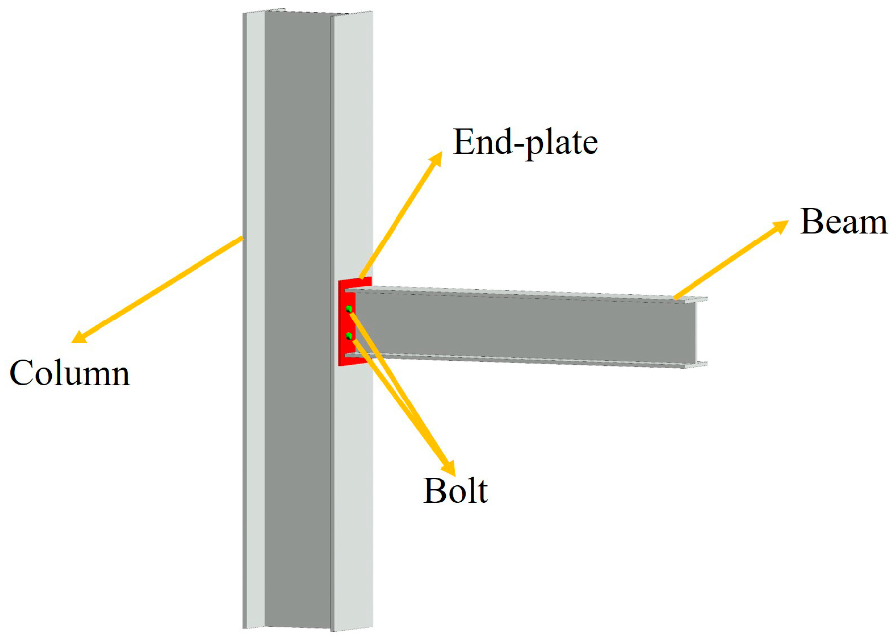
3. Damage State of FEP Connections
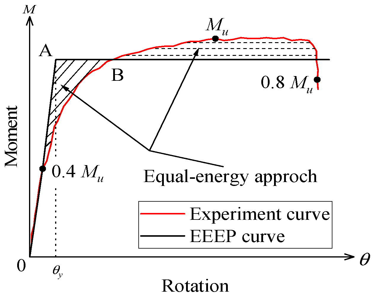
3.1. Rotation Factor
3.2. Virtually Undamaged State
3.3. Lightly Damaged State
3.4. Moderately Damaged State
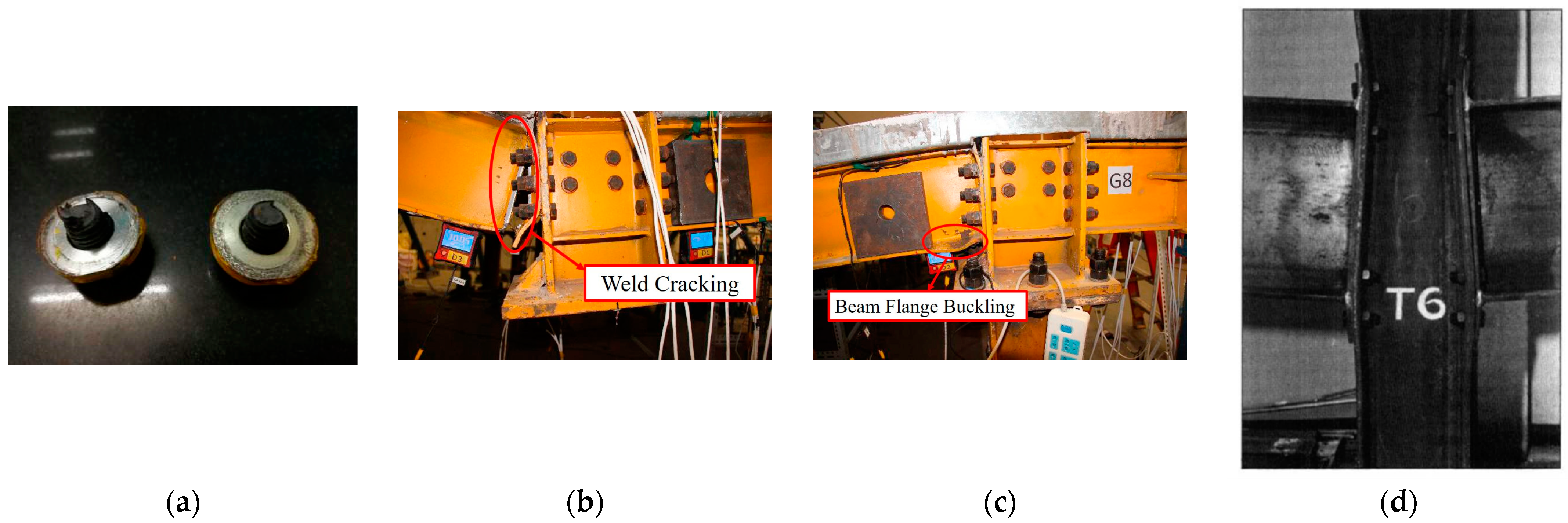
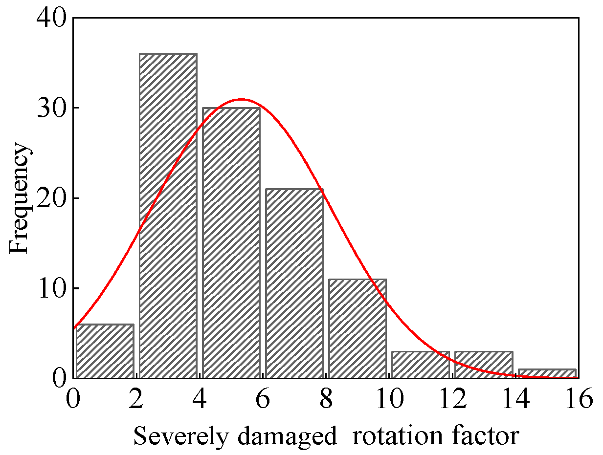
3.5. Severely Damaged State
4. Effect of Different Parameters on Rotation Factor
4.1. Thickness of End Plate
4.2. Selection of End-Plate Thickness According to Different Codes
4.3. Bolt Diameter
4.4. Selection of Bolt Diameters According to Different Codes
5. Experiment Verification
5.1. Introduction
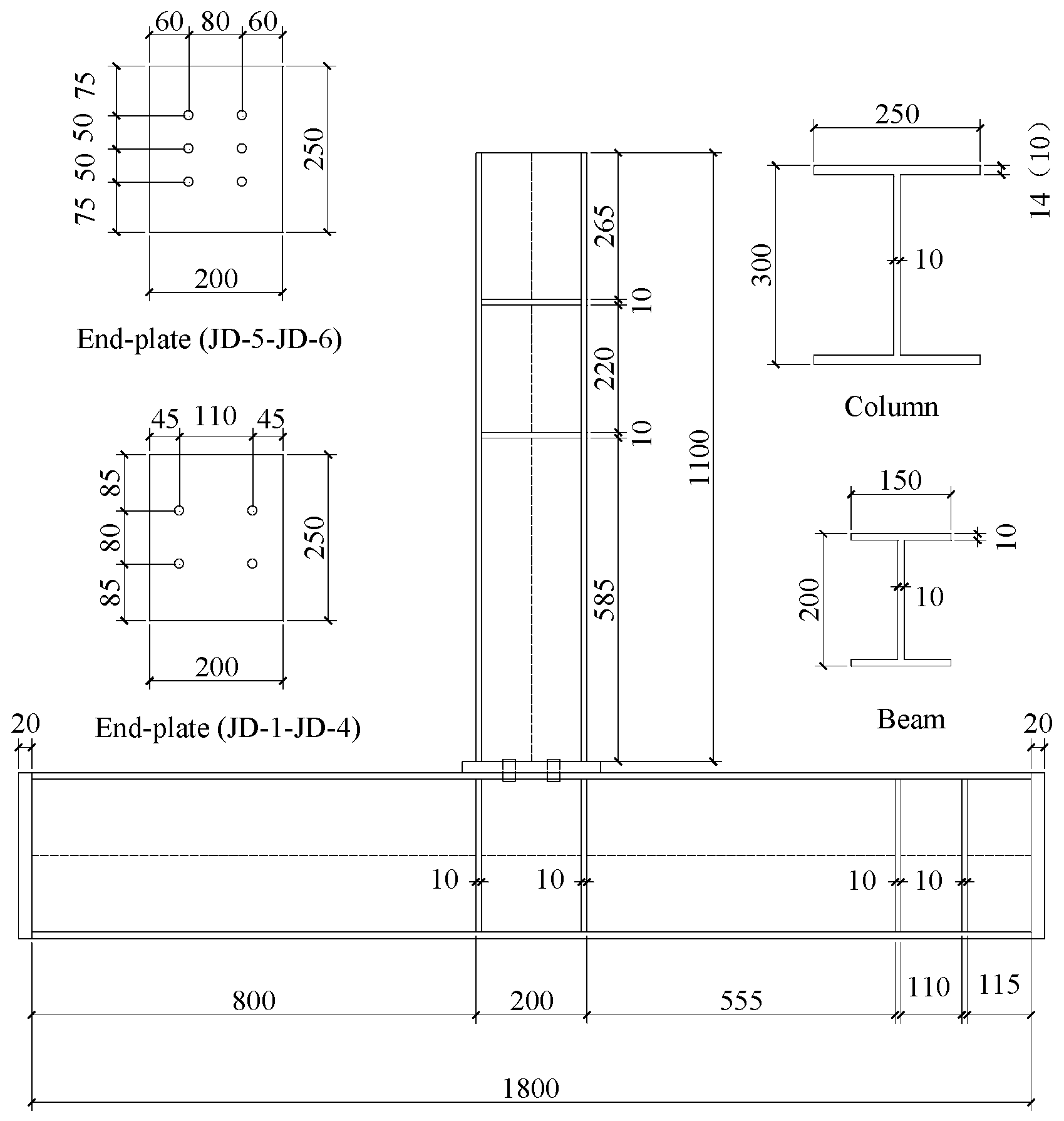
5.2. Experiment Overview
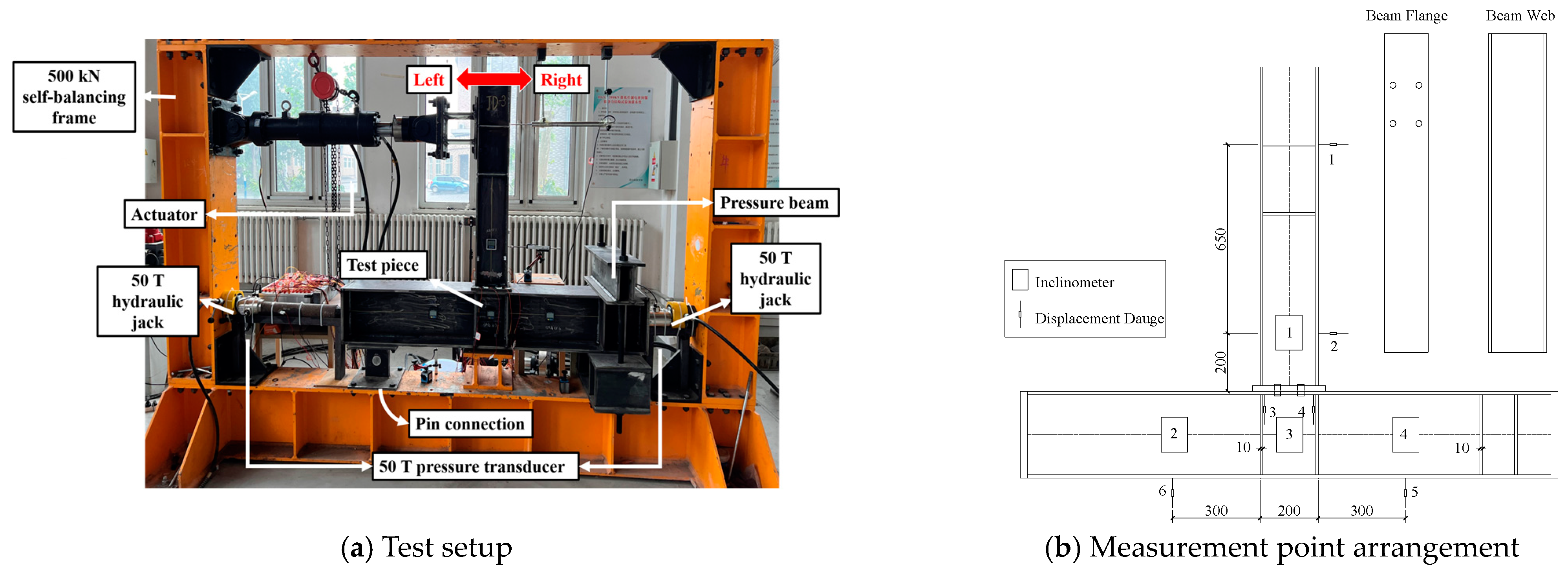
5.3. Experimental Setup and Loading System
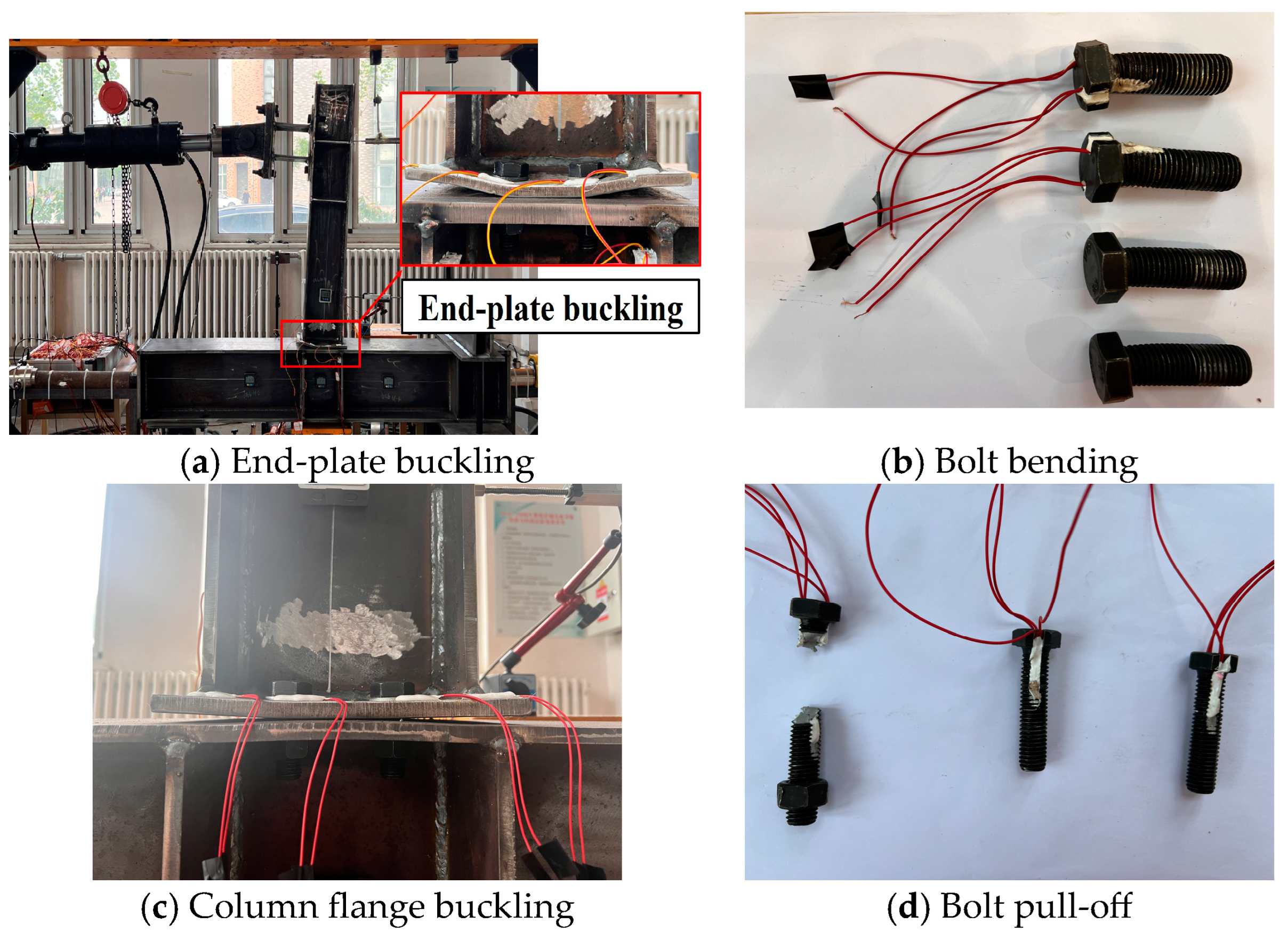
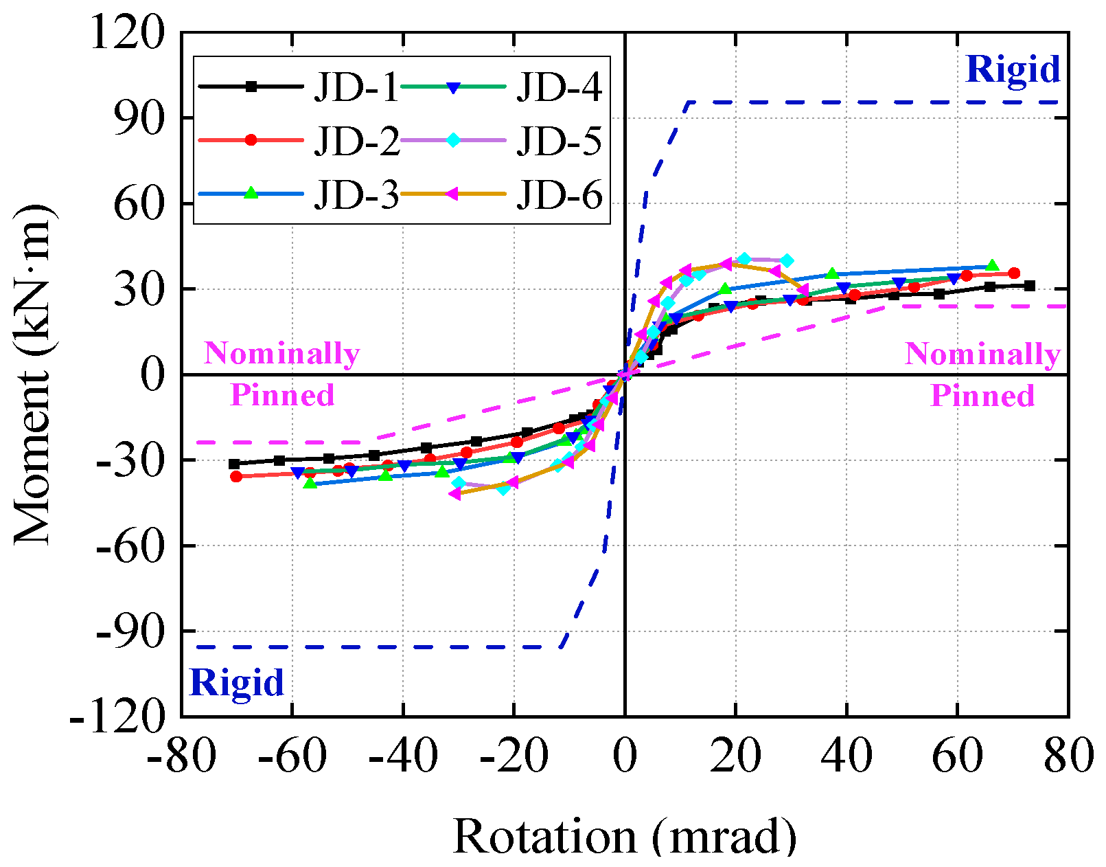
5.4. Test Phenomena and Skeleton Curve
5.5. Comparison of Rotation Factors
6. Conclusions
Author Contributions
Funding
Data Availability Statement
Conflicts of Interest
References
- Gao, W.J.; Tang, G.W.; Lin, K. Earthquake Hazard to Steel Frame and Anti-earthquake Investigation. Technol. Highw. Transport. 2008, S2, 66–69. [Google Scholar]
- Gross, J.L. A connection model for the seismic analysis of welded steel moment frames. Eng. Struct. 1998, 20, 390–397. [Google Scholar] [CrossRef]
- Mahin, S.A. Lessons from damage to steel buildings during the Northridge earthquake. Eng. Struct. 1998, 20, 261–270. [Google Scholar] [CrossRef]
- Huang, B.S. Seismic Damage to Building Steel Structures in the Kobe Earthquake in Japan and Implications. Build. Struct. 2000, 9, 24–25. [Google Scholar] [CrossRef]
- Xiong, C.; Guo, Y.J.; Li, X. Research on mechanical properties of flush end plate semi-rigid beam-column joints. China Sci. Pap. 2019, 14, 1066–1071. [Google Scholar]
- Coelho, A.M.G.; Bijlaard, F.S. Experimental behaviour of high strength steel end-plate connections. J. Constr. Steel Res. 2006, 63, 1228–1240. [Google Scholar] [CrossRef]
- Coelho, A.M.G.; Bijlaard, F.S.; da Silva, L.S. Experimental assessment of the ductility of extended end plate connections. Eng. Struct. 2004, 26, 1185–1206. [Google Scholar] [CrossRef]
- Broderick, B.; Thomson, A. The response of flush end-plate joints under earthquake loading. J. Constr. Steel Res. 2002, 58, 1161–1175. [Google Scholar] [CrossRef]
- ENV 1993-1-8:2005; Eurocode 3: Design of Steel Structures—Part 1.8: Design of Joints. CEN: Brussels, Belgium, 2005.
- Faridmehr, I.; Tahir, M.M.; Lahmer, T. Classification System for Semi-Rigid Beam-to-Column Connections. Lat. Am. J. Solids Struct. 2016, 13, 2152–2175. [Google Scholar] [CrossRef]
- ANSI/AISC360-10; Specification for Structural Steel Buildings. American Institute of Steel Construction: Chicago, IL, USA, 2016.
- Qiang, X.H.; Ren, C.C.; Jiang, X.; Huang, Z. Experimental and Theoretical Study on Behavior of High Strength Steel Flush Endplate Connections under Fire Conditions. J. Tongji Univer. Nat. Sci. 2017, 45, 673–683. [Google Scholar] [CrossRef]
- Shi, G. Static and Seismic Behavior of Semirigid End-plate Connections in Steel Frames. Ph.D. Thesis, Tsinghua University, Beijing, China, 2004. [Google Scholar]
- Sun, F.F.; Sun, M.; Li, G.Q.; Xiao, Y.; Wei, M.; Liu, L. Experimental study on seismic behavior of high-strength steel beam-to-column end-plate connections. J. Build. Struct. 2014, 35, 116–124. [Google Scholar] [CrossRef]
- GB 50011-2010; Code for Seismic Design of Buildings. Ministry of Housing and Urban-Rural Development of the People’s Republic of China: Beijing, China, 2010.
- JGJ 99-2015; Technical Specification for Steel Structure of Tall Building. Ministry of Housing and Urban-Rural Development of the People’s Republic of China: Beijing, China, 2016.
- Thomson, A.W.; Broderick, B.M. Earthquake resistance of flush end-plate steel joints for moment frames. Proc. Inst. Civ. Eng. Struct. Build. 2002, 152, 157–165. [Google Scholar] [CrossRef]
- Abolmaali, A. Nonlinear Dynamic Finite Element Analysis of Steel Frames with Semi-Rigid Joints. Ph.D. Thesis, University of Oklahoma, Norman, OK, USA, 1999. [Google Scholar]
- Wang, Y.; Wang, Z.; Pan, J.; Wang, P. Seismic Behavior of a Novel Blind Bolted Flush End-Plate Connection to Strengthened Concrete-Filled Steel Tube Columns. Appl. Sci. 2020, 10, 2517. [Google Scholar] [CrossRef]
- Dong, S. Experimental Research on Behavior of Flush End-plate Composite Joints under Positive Moment. Master’s Thesis, Nanjing University of Technology, Nanjing, China, 2006. [Google Scholar]
- Shek, P.; Tahir, M.; Sulaiman, A.; Tan, C. Experimental Evaluation of Flush End—Plate Connection with Built-up Hybrid Beam Section. Adv. Struct. Eng. 2012, 15, 331–341. [Google Scholar] [CrossRef]
- Zheng, D.S. Experimental Study on Seismic Behaviours of Flush End-Plate Composite Joints. Master’s Thesis, Nanjing University of Technology, Nanjing, China, 2005. [Google Scholar]
- Lu, Y.; Zhang, L.; Jiang, Y.H. Bearing Capacity for Flush End-plated Connections Between Rectangular Tubular Columns and H-shaped Beams with Single Direction Bolts. J. Tongji Univ. Nat. Sci. 2018, 46, 162–169. [Google Scholar] [CrossRef]
- Lu, P.; Yang, J.; Ran, T.; Wang, W. Experimental study on flexural capacity and fire resistance of high strength Q690 steel flush end-plate connections. Thin-Walled Struct. 2023, 184, 110506. [Google Scholar] [CrossRef]
- Loh, H.; Uy, B.; Bradford, M. The effects of partial shear connection in composite flush end plate joints Part I—Experimental study. J. Constr. Steel Res. 2005, 62, 378–390. [Google Scholar] [CrossRef]
- Lin, R.D. Finite Element and Experiment Analysis on Flush End-plate Beam-column Joint of Portal Frame. Ind. Constr. 2012, 42, 128–132+138. [Google Scholar] [CrossRef]
- Aydın, A.C.; Maali, M.; Kılıç, M.; Sağıroğlu, M. Experimental investigation of sinus beams with end-plate connections. Thin-Walled Struct. 2015, 97, 35–43. [Google Scholar] [CrossRef]
- Keipour, N.; Valipour, H.; Bradford, M. Experimental study of steel-timber composite (STC) beam to steel column joints having a flush end-plate. Eng. Struct. 2018, 174, 906–918. [Google Scholar] [CrossRef]
- da Silva, L.S.; de Lima, L.R.; Vellasco, P.C.d.S.; de Andrade, S.A. Behaviour of flush end-plate beam-to-column joints under bending and axial force. Steel Compos. Struct. 2004, 4, 77–94. [Google Scholar] [CrossRef]
- Li, D.S. Research on Mechanical Behavior of Concrete Filled Steel Tubular Column-Steel Beam Blind Bolted Joints. Ph.D. Thesis, Fuzhou University, Fuzhou, China, 2016. [Google Scholar]
- Wang, J.-F.; Han, L.-H.; Uy, B. Hysteretic behaviour of flush end plate joints to concrete-filled steel tubular columns. J. Constr. Steel Res. 2009, 65, 1644–1663. [Google Scholar] [CrossRef]
- Mohamed, N.; Farghaly, A.S.; Benmokrane, B.; Neale, K.W. Drift Capacity Design of Shear Walls Reinforced with Glass Fiber-Reinforced Polymer Bars. ACI Struct. J. 2014, 111, 1397. [Google Scholar] [CrossRef]
- E2126-11; Standard Test Methods for Cyclic (Reversed) Load Test for Shear Resistance of Vertical Elements of the Lateral Force Resisting Systems for Buildings1. American Society for Testingand Materials International: West Conshohocken, PA, USA, 2011.
- Liu, H.-Y.; Yang, B.; Kang, S.-B. Testing and analysis of composite floor systems under peripheral column removal scenarios. Procedia Eng. 2017, 210, 261–268. [Google Scholar] [CrossRef]
- Youngson, G.K.; Wang, Z.M.; Bose, B. An appraisal of the design rules in eurocode 3 for bolted end-plate joints by comparison with experimental results. Proc. Inst. Civ. Eng. Struct. Build. 1996, 116, 221–234. [Google Scholar] [CrossRef]
- GB51022-2015; Technical Code for Steel Structure of Light-Weight Building with Gabled Frames. Ministry of Housing and Urban-Rural Development of the People’s Republic of China: Beijing, China, 2015.
- CECS 260:2009; Technical Specification for Steel Structures with End-Plate Semi-Rigid Connection. China Association for Engineering Construction: Beijing, China, 2009.
- Design Guide 16: Flush and Extended Multiple-Row Moment End-Plate Connections. American Institute of Steel Construction, Chicago. 2002. Available online: https://www.aisc.org/Design-Guide-16-Flush-and-Extended-Multiple-Row-Moment-End-Plate-Connections (accessed on 6 September 2023).
- GB 50017-2017; Standard for Design of Steel Structures. Ministry of Housing and Urban-Rural Development of the People’s Republic of China: Beijing, China, 2017.


| No. | Origin | Specimen No. | Column Section | Beam Section | End-Plate Thickness/mm | High-Strength Bolt | Loading Method |
|---|---|---|---|---|---|---|---|
| 1 | C. Xiong [5] | 150 × 150 × 4 × 6 | 150 × 150 × 4 × 6 | 16 | M20 | Monotonic | |
| 2 | Ana M. Girão Coelho [6] | F1EP_15_2 | HE300M | HE320A | 15 | M24 | Monotonic |
| 3 | F2EP_15_2 | HE300M | HE320A | 15 | M24 | Monotonic | |
| 4 | F1EP_10_2 | HE300M | HE320A | 10 | M24 | Monotonic | |
| 5 | F2EP_10_2 | HE300M | HE320A | 10 | M24 | Monotonic | |
| 6 | B.M. Broderick [8] | EP1 | 203 × 203 × 86 UC | 254 × 102 × 22 UB | 8 | M20 | Cyclic |
| 7 | EP2 | 203 × 203 × 86 UC | 254 × 102 × 22 UB | 12 | M20 | Cyclic | |
| 8 | EP3 | 203 × 203 × 86 UC | 254 × 146 × 37 UB | 12 | M20 | Monotonic | |
| 9 | EP4 | 203 × 203 × 86 UC | 254 × 146 × 37 UB | 12 | M20 | Cyclic | |
| 10 | EP5 | 203 × 203 × 86 UC | 254 × 146 × 37 UB | 12 | M20 | Cyclic | |
| 11 | EP6 | 203 × 203 × 86 UC | 254 × 146 × 37 UB | 20 | M16 | Monotonic | |
| 12 | EP7 | 203 × 203 × 86 UC | 254 × 146 × 37 UB | 20 | M16 | Cyclic | |
| 13 | EP8 | 203 × 203 × 86 UC | 254 × 146 × 37 UB | 20 | M16 | Cyclic | |
| 14 | Iman Faridmehr [10] | FEP1 | HB 200 × 200 × 56.2 | HB250 × 125 × 25.1 | 12 | M20 | Monotonic |
| 15 | FEP2 | HB 200 × 200 × 56.2 | HB250 × 125 × 25.1 | 15 | M24 | Monotonic | |
| 16 | FEP3 | HB250 × 250 × 63.8 | HB400 × 200 × 65.4 | 12 | M20 | Monotonic | |
| 17 | FEP4 | HB250 × 250 × 63.8 | HB400 × 200 × 65.4 | 12 | M20 | Monotonic | |
| 18 | FEP5 | HB300 × 300 × 83.5 | HB500 × 200 × 102 | 15 | M24 | Monotonic | |
| 19 | FEP6 | HB300 × 300 × 83.5 | HB500 × 200 × 102 | 15 | M24 | Monotonic | |
| 20 | X.H. Qiang [12] | 1-1A | HW407 × 428 × 20 × 35 | HW300 × 300 × 10 × 15 | 20 | M27 | Monotonic |
| 21 | 1-2A | HW407 × 428 × 20 × 35 | HW300 × 300 × 10 × 15 | 12 | M27 | Monotonic | |
| 22 | 1-3A | HW407 × 428 × 20 × 35 | HW300 × 300 × 10 × 15 | 10 | M27 | Monotonic | |
| 23 | 2-1A | HW407 × 428 × 20 × 35 | HW300 × 300 × 10 × 15 | 25 | M27 | Monotonic | |
| 24 | 2-2A | HW407 × 428 × 20 × 35 | HW300 × 300 × 10 × 15 | 20 | M27 | Monotonic | |
| 25 | 2-3A | HW407 × 428 × 20 × 35 | HW300 × 300 × 10 × 15 | 15 | M27 | Monotonic | |
| 26 | 2-4A | HW407 × 428 × 20 × 35 | HW300 × 300 × 10 × 15 | 12 | M27 | Monotonic | |
| 27 | G. Shi [13] | SC1 | 300 × 200 × 8 × 12 | 300 × 200 × 8 × 12 | 20 | M20 | Monotonic |
| 28 | JD-1 | 300 × 200 × 8 × 12 | 300 × 200 × 8 × 12 | 20 | M20 | Cyclic | |
| 29 | F.F. Sun [14] | SR1 | H400 × 250 × 24 × 40 | H380 × 250 × 20 × 30 | 18 | M24 | Cyclic |
| 30 | SR2 | H400 × 250 × 24 × 40 | H380 × 250 × 20 × 30 | 16 | M24 | Cyclic | |
| 31 | SR3 | H400 × 250 × 16 × 16 | H380 × 250 × 20 × 30 | 16 | M24 | Cyclic | |
| 32 | A. W. Thomson [17] | J1 | 203 × 203 × 86 UC | 254 × 146 × 37 UB | 10 | M20 | Cyclic |
| 33 | J2 | 203 × 203 × 86 UC | 254 × 146 × 37 UB | 10 | M20 | Cyclic | |
| 34 | J3 | 203 × 203 × 86 UC | 254 × 146 × 37 UB | 15 | M20 | Cyclic | |
| 35 | J4 | 203 × 203 × 86 UC | 254 × 146 × 37 UB | 15 | M20 | Cyclic | |
| 36 | J5 | 203 × 203 × 52 UC | 254 × 146 × 37 UB | 12 | M20 | Cyclic | |
| 37 | J6 | 203 × 203 × 52 UC | 254 × 146 × 37 UB | 12 | M20 | Cyclic | |
| 38 | J7 | 203 × 203 × 86 UC | 254 × 146 × 37 UB | 12 | M20 | Cyclic | |
| 39 | J8 | 203 × 203 × 86 UC | 254 × 146 × 37 UB | 12 | M20 | Cyclic | |
| 40 | Ali Abolmaali [18] | Test 1 | 305 × 203 × 25 × 10 | 457 × 152 × 13 × 6 | 9.525 | M19 | Cyclic |
| 41 | Test 2 | 305 × 203 × 25 × 10 | 457 × 152 × 13 × 6 | 12.7 | M19 | Cyclic | |
| 49 | Test 3 | 305 × 203 × 25 × 10 | 457 × 152 × 13 × 6 | 15.875 | M19 | Cyclic | |
| 50 | Test 4 | 305 × 203 × 25 × 10 | 457 × 203 × 13 × 6 | 9.525 | M25 | Cyclic | |
| 51 | Test 5 | 305 × 203 × 25 × 10 | 457 × 203 × 13 × 6 | 12.7 | M25 | Cyclic | |
| 52 | Test 6 | 305 × 203 × 25 × 10 | 457 × 203 × 13 × 6 | 19.05 | M25 | Cyclic | |
| 53 | Test 7 | 305 × 203 × 25 × 10 | 559 × 152 × 13 × 6 | 9.525 | M19 | Cyclic | |
| 54 | Test 8 | 305 × 203 × 25 × 10 | 559 × 152 × 13 × 6 | 12.7 | M19 | Cyclic | |
| 55 | Test 9 | 305 × 203 × 25 × 10 | 559 × 152 × 13 × 6 | 15.875 | M19 | Cyclic | |
| 56 | Test 10 | 305 × 203 × 25 × 10 | 559 × 203 × 13 × 6 | 9.525 | M25 | Cyclic | |
| 57 | Test 12 | 350 × 203 × 25 × 10 | 559 × 203 × 13 × 6 | 15.875 | M25 | Cyclic | |
| 58 | Y, H. Wang [19] | ST-1 | 250 × 250 × 5 | HN350 × 175 × 7 × 11 | 12 | M16 | Cyclic |
| 59 | ST-2 | 250 × 250 × 5 | HN350 × 175 × 7 × 11 | 24 | M16 | Cyclic | |
| 60 | ST-3 | 250 × 250 × 5 | HN350 × 175 × 7 × 11 | 12 | M16 | Cyclic | |
| 61 | ST-4 | 250 × 250 × 5 | HN350 × 175 × 7 × 11 | 24 | M16 | Cyclic | |
| 62 | ST-5 | 250 × 250 × 5 | HN350 × 175 × 7 × 11 | 24 | M16 | Cyclic | |
| 63 | ST-6 | 250 × 250 × 5 | HN300 × 150 × 6 × 9 | 24 | M16 | Cyclic | |
| 64 | S. Dong [20] | J13 | H200 × 200 × 8 × 12 | H250 × 125 × 6 × 9 | 14 | M20 | Monotonic |
| 65 | J14 | H200 × 200 × 8 × 12 | H250 × 125 × 6 × 9 | 14 | M20 | Monotonic | |
| 66 | P.N. Shek [21] | N1 | 305 × 305 × 118 UC | 400 × 140 × 5 × 12 | 12 | M20 | Monotonic |
| 67 | N2 | 305 × 305 × 118 UC | 500 × 180 × 5 × 16 | 12 | M20 | Monotonic | |
| 68 | N3 | 305 × 305 × 118 UC | 450 × 160 × 5 × 12 | 12 | M20 | Monotonic | |
| 69 | N4 | 305 × 305 × 118 UC | 600 × 200 × 6 × 16 | 12 | M20 | Monotonic | |
| 70 | D.S. Zheng [22] | J21 | H200 × 200 × 8 × 12 | H250 × 125 × 6 × 9 | 14 | M20 | Cyclic |
| 71 | J22 | H200 × 200 × 8 × 12 | H250 × 125 × 6 × 9 | 14 | M20 | Cyclic | |
| 72 | J23 | H200 × 200 × 8 × 12 | H250 × 125 × 6 × 9 | 14 | M20 | Cyclic | |
| 73 | J24 | H200 × 200 × 8 × 12 | H250 × 125 × 6 × 9 | 14 | M20 | Cyclic | |
| 74 | G.Q. Li [23] | SR1-1 | 200 × 12 | HN300 × 150 × 6.5 × 9 | 14 | M16 | Monotonic |
| 75 | SR1-2 | 200 × 12 | HN300 × 150 × 6.5 × 9 | 14 | M16 | Monotonic | |
| 76 | SR2-1 | 200 × 12 | HN300 × 150 × 6.5 × 9 | 10 | M16 | Monotonic | |
| 77 | SR2-2 | 200 × 12 | HN300 × 150 × 6.5 × 9 | 10 | M16 | Monotonic | |
| 78 | SR3-1 | 200 × 8 | HN300 × 150 × 6.5 × 9 | 14 | M16 | Monotonic | |
| 79 | SR3-2 | 200 × 8 | HN300 × 150 × 6.5 × 9 | 14 | M16 | Monotonic | |
| 80 | Peng Lu [24] | J-8-A | H300 × 200 × 8 × 12 | H300 × 180 × 8 × 12 | 8 | M22 | Monotonic |
| 81 | J-12-A | H300 × 200 × 8 × 12 | H300 × 180 × 8 × 12 | 12 | M22 | Monotonic | |
| 82 | H.Y. Loha [25] | CJ1 | 200 × 200 × 9 | 250UB25.7 | 10 | M20 | Monotonic |
| 83 | CJ2 | 200 × 200 × 9 | 250UB25.7 | 10 | M20 | Monotonic | |
| 84 | CJ3 | 200 × 200 × 9 | 250UB25.7 | 10 | M20 | Monotonic | |
| 85 | CJ4 | 200 × 200 × 9 | 250UB25.7 | 10 | M20 | Monotonic | |
| 86 | CJ5 | 200 × 200 × 9 | 250UB25.7 | 10 | M20 | Monotonic | |
| 87 | R.D. Lin [26] | S1 | — | BH520 × 199 × 8 × 12 | 20 | M20 | Monotonic |
| 88 | S2 | — | BH520 × 199 × 8 × 12 | 11 | M20 | Monotonic | |
| 89 | S3 | — | BH520 × 199 × 8 × 12 | 11 | M20 | Monotonic | |
| 90 | S4 | — | BH520 × 199 × 8 × 12 | 11 | M20 | Monotonic | |
| 91 | Abdulkadir Cüneyt Aydın [27] | Simple | — | 160 × 150 × 4 × 2.5 | 8 | M10 | Monotonic |
| 92 | Sinusoidal 30° | — | 160 × 150 × 4 × 2.5 | 8 | M10 | Monotonic | |
| 93 | Sinusoidal 70° | — | 160 × 150 × 4 × 2.5 | 8 | M10 | Monotonic | |
| 94 | IPE 160 | — | 160 × 82 × 7.4 × 5 | 8 | M10 | Monotonic | |
| 95 | N. Keipour [28] | SJ | 250UC72.9 | 310UB40.4 | 10 | M24 | Monotonic |
| 96 | TJ1 | 250UC72.9 | 310UB40.4 | 10 | M24 | Monotonic | |
| 97 | TJ2 | 250UC72.9 | 310UB40.4 | 10 | M24 | Monotonic | |
| 98 | TJ3 | 250UC72.9 | 310UB40.4 | 10 | M24 | Monotonic | |
| 99 | TJ4 | 250UC72.9 | 310UB40.4 | 10 | M24 | Monotonic | |
| 100 | TJ5 | 250UC72.9 | 310UB40.4 | 10 | M24 | Monotonic | |
| 101 | Luís Simões da Silva [29] | FE1 | HEB240 | IEP240 | 15 | M20 | Monotonic |
| 102 | FE3 | HEB240 | IEP240 | 15 | M20 | Monotonic | |
| 103 | FE4 | HEB240 | IEP240 | 15 | M20 | Monotonic | |
| 104 | FE5 | HEB240 | IEP240 | 15 | M20 | Monotonic | |
| 105 | FE6 | HEB240 | IEP240 | 15 | M20 | Monotonic | |
| 106 | FE7 | HEB240 | IEP240 | 15 | M20 | Monotonic | |
| 107 | FE8 | HEB240 | IEP240 | 15 | M20 | Monotonic | |
| 108 | FE9 | HEB240 | IEP240 | 15 | M20 | Monotonic | |
| 109 | D.S. Li [30] | C1 | 200 × 6 | 300 × 150 × 6.5 × 9 | 14 | M20 | Cyclic |
| 110 | C2 | 200 × 6 | 300 × 150 × 6.5 × 9 | 14 | M20 | Cyclic | |
| 111 | C3 | 200 × 6 | 300 × 150 × 6.5 × 9 | 14 | M20 | Cyclic | |
| 112 | C4 | 200 × 6 | 300 × 150 × 6.5 × 9 | 14 | M20 | Cyclic | |
| 113 | C5 | 200 × 6 | 300 × 150 × 6.5 × 9 | 14 | M20 | Cyclic | |
| 114 | C6 | 200 × 6 | 300 × 150 × 6.5 × 9 | 14 | M20 | Cyclic | |
| 115 | J.F. Wang [31] | MTF1 | 200 × 1.5 | HN300 × 150 × 6 × 10 | 12 | M20 | Cyclic |
| 116 | MTF2 | 200 × 3.0 | HN300 × 150 × 6 × 10 | 12 | M20 | Cyclic |
| Thickness of End Plate/mm | Median | 95% Lower Confidence Limit |
|---|---|---|
| 3.32 | 1.50 | |
| 7.41 | 5.30 | |
| 6.36 | 5.64 | |
| 5.33 | 5.59 | |
| 3.74 | 2.05 | |
| 4.86 | 3.29 |
| Bolt Diameter | Median | 95% Lower Confidence Limit |
|---|---|---|
| M10 | 2.95 | 0.95 |
| M16 | 5.17 | 3.63 |
| M20 | 7.60 | 7.14 |
| M24 | 4.25 | 3.23 |
| M27 | 6.65 | 5.16 |
| Specimen No. | Column Section | Bolt Diameter | End-Plate Thickness/mm | Bolt Number |
|---|---|---|---|---|
| JD-1 | HW300 × 250 × 10 × 14 | M20 | 8 | 4 |
| JD-2 | HW300 × 250 × 10 × 14 | M20 | 10 | 4 |
| JD-3 | HW300 × 250 × 10 × 14 | M20 | 12 | 4 |
| JD-4 | HW300 × 250 × 10 × 10 | M20 | 12 | 4 |
| JD-5 | HW300 × 250 × 10 × 14 | M14 | 12 | 6 |
| JD-6 | HW300 × 250 × 10 × 14 | M16 | 12 | 6 |
| Material Specimen Thickness, t/mm | Yield Strength, fy/MPa | Ultimate Strength, fu/MPa | Elastic Modulus, E/GPa |
|---|---|---|---|
| 8.00 | 261.05 | 413.77 | 198.22 |
| 10.00 | 267.21 | 426.43 | 195.69 |
| 12.00 | 277.10 | 429.33 | 199.31 |
| 14.00 | 293.64 | 471.00 | 179.42 |
| Specimen No. | Damage Pattern |
|---|---|
| JD-1 | End plate yielded and buckled significantly |
| JD-2 | End plate yielded and buckled significantly |
| JD-3 | End plate yielded and bolt deformed significantly |
| JD-4 | End plate yielded and column flange warped significantly |
| JD-5 | Tension bolt fracture |
| JD-6 | Stripped bolt threads |
| Damage State | Average Experimental Rotation Factor | Average Theoretical Rotation Factor | Theoretical 95% Lower Confidence Limit Value of Rotation Factor | Experimental Phenomena | Recommendations |
|---|---|---|---|---|---|
| Virtually undamaged state | The joints are basically intact, with gaps between the end plates near the flanges of the tension beams and the flanges of the columns. | The joints are basically intact, and a gap exists between the end plate near the flange of the tension beam and the column flange. | |||
| Lightly damaged state | The gap between the column flange and the tensile end plate is larger, while significant buckling of the end plates on both sides occurs. | The gap between the flange of the tension beam and the end plate is larger, and the end plate is obviously bent. | |||
| Moderately damaged state | Increased buckling of end plates, significant buckling of pressurized beam flanges, and bulging of column flanges are observed. | The extent of bending of the end plate increases, and the flange of the compressed column is obviously bent. | |||
| Severely damaged state | Bolts are pulled off, and threads are stripped. Welds between end plates and beam flanges are broken, and column flanges or webs are deformed. | The bolt is broken, and thread is peeled off. The weld between the end plate and the beam flange is broken, and the flange of the compression column deforms. | |||
| Joint failure | λ ≥ 4.81 | λ ≥ 5.31 | λ ≥ 4.77 | —— | —— |
Disclaimer/Publisher’s Note: The statements, opinions and data contained in all publications are solely those of the individual author(s) and contributor(s) and not of MDPI and/or the editor(s). MDPI and/or the editor(s) disclaim responsibility for any injury to people or property resulting from any ideas, methods, instructions or products referred to in the content. |
© 2024 by the authors. Licensee MDPI, Basel, Switzerland. This article is an open access article distributed under the terms and conditions of the Creative Commons Attribution (CC BY) license (https://creativecommons.org/licenses/by/4.0/).
Share and Cite
Su, J.; Zhou, J.; Liu, W.; Li, Y.; Yu, H.; Li, Q. Study on Damage Index for Beam–Column Joints with Flush End-Plate Connections. Buildings 2024, 14, 3637. https://doi.org/10.3390/buildings14113637
Su J, Zhou J, Liu W, Li Y, Yu H, Li Q. Study on Damage Index for Beam–Column Joints with Flush End-Plate Connections. Buildings. 2024; 14(11):3637. https://doi.org/10.3390/buildings14113637
Chicago/Turabian StyleSu, Jizhi, Jinpu Zhou, Weiran Liu, Yong Li, Haifeng Yu, and Qilian Li. 2024. "Study on Damage Index for Beam–Column Joints with Flush End-Plate Connections" Buildings 14, no. 11: 3637. https://doi.org/10.3390/buildings14113637
APA StyleSu, J., Zhou, J., Liu, W., Li, Y., Yu, H., & Li, Q. (2024). Study on Damage Index for Beam–Column Joints with Flush End-Plate Connections. Buildings, 14(11), 3637. https://doi.org/10.3390/buildings14113637