Abstract
To address loading and unloading issues in civil and hydraulic engineering projects that employ coarse-grained soil as fill material under plane strain conditions during construction and operation, cyclic loading–unloading large-scale plane strain tests were conducted on two types of coarse-grained soils. The effects of coarse-grained soil properties on shear behavior and various modulus relationships were analyzed. The research results showed that coarse-grained soils with better particle roundness exhibit significant shear dilation deformation; it was also found that low parent rock strength can lead to strain softening, and an increase in confining pressure suppresses shear dilation deformation. During the cyclic loading–unloading process, the initial unloading modulus (Eiu) > unloading–reloading modulus (Eur) > initial reloading modulus (Eir) > initial tangent modulus (Ei), with the unloading modulus considerably greater than the others. In finite element simulations and model calculations, it is essential to select appropriate modulus parameters based on the stress conditions of the soil to ensure calculation accuracy. In this work, an elastoplastic and nonlinear elastic theory was used to establish a cyclic loading–unloading constitutive model. By comparing the values obtained using this model with experimental measurements, it was found that the model can reasonably predict stress–strain variations during cyclic loading–unloading of coarse-grained soils under plane strain conditions.
1. Introduction
Coarse-grained soils possess excellent engineering properties such as high shear strength, large bearing capacity, good stability, and high permeability. Because of this, they are widely used in hydraulic and transportation engineering [1,2,3]. Civil and hydraulic projects, such as rockfill dams, slope protections, tunnels, and high embankments, involve the use of engineering structures, which have longitudinal lengths much greater than their transverse lengths. The longitudinal ends have constraints that prevent deformation in that direction, causing strain to develop more easily toward transverse sections where constraints are weaker. This strain boundary condition is known as the plane strain condition [4,5]. Therefore, it is more reasonable to study such engineering under plane strain conditions [6,7,8,9]. The plane strain conditions cause the soil mass to exhibit mechanical and strength characteristics, which are different from those exhibited under triaxial conditions [10,11]. Lu et al. [12] studied the principal stress in the direction of plane strain of soil and verified the rationality of the bilinear principal stress function. Pan et al. [13] carried out true triaxial tests and plane strain tests on sandstone rubble with different values for the intermediate principal stress ratio. Their results indicated that the contribution of intermediate principal stress to the enhancement of specimen strength was essentially reflected. Jiang et al. [14] conducted true triaxial tests and plane strain tests on rubble with four different lithologies; their results revealed strength parameters that were significantly greater than in conventional triaxial tests.
During the construction and operation stages of engineering projects, soil mass is usually subjected to single or multiple stress loading unloading effects. Examples include the rise and fall of water levels in reservoirs and rivers, the arrival and departure of heavy construction machinery, the piling up of excavated soil, and the asymmetric excavation of tunnels [15,16,17,18]. The repeated application and removal of loads can damage engineering structures and affect the stability of geotechnical bodies, impacting the efficient operation of engineering projects and potentially triggering engineering disasters. Ji et al. [19] analyzed the three-dimensional evolutionary mechanisms and deformation characteristics involved in reservoir bank collapses and suggested that the repeated rise and fall of the reservoir water level, along with the erosive action of water, are likely to lead to the collapse of the reservoir banks. Currently, research on the unloading and reloading of soil and rock is primarily focused on traditional conventional triaxial tests [20,21,22,23,24,25,26,27]. However, conventional triaxial tests cannot accurately reflect the complex stress path issues associated with changes in three-dimensional stress states. Therefore, studying the mechanical behavior of gravel under loading–unloading stress paths in a three-dimensional stress state can better reflect the stress state changes in coarse-grained soils. Wang et al. [28] conducted true triaxial tests on sandstone to study instability and failure characteristics in the surrounding rock under different disturbance stresses during the excavation unloading of deep underground tunnels. Wang et al. [29] conducted research on the deformation and failure characteristics of red sandstone via true triaxial loading and unloading tests, and the Mogi-Coulomb strength criterion can better reflect the strength failure characteristics of red sandstone during loading and unloading processes. Liu et al. [30] conducted undrained true triaxial tests on natural undisturbed clay and studied the permanent deformation of natural undisturbed clay under three-dimensional cyclic stress, and then established an empirical formula for predicting the permanent principal strain under three-dimensional cyclic stress. Wang et al. [31] conducted large-scale true triaxial loading and unloading tests on coarse-grained materials, analyzed the variation patterns of rebound shear modulus and proposed an estimation model for unloading rebound modulus.
In this study, a series of large-scale plane strain cyclic loading unloading tests were conducted on two types of coarse-grained soils with different particle circularities to address the safety and stability issues of the roadway and other plane strain types of engineering. The stress–strain response of the coarse-grained soil under a reciprocating stress path was tested. Based on the experimental results, the modulus of the coarse-grained soil under cyclic loading unloading stress path conditions was analyzed, and then a cyclic loading–unloading constitutive model with plane strain conditions was established. This model can predict the stress–strain behavior of reloading after unloading and accurately predict the deformation during high-stress unloading based on the unique mechanical characteristics of the soil mass during unloading.
2. Coarse-Grained Soil, Apparatus, and Scheme
2.1. Physical Properties of Coarse-Grained Soil
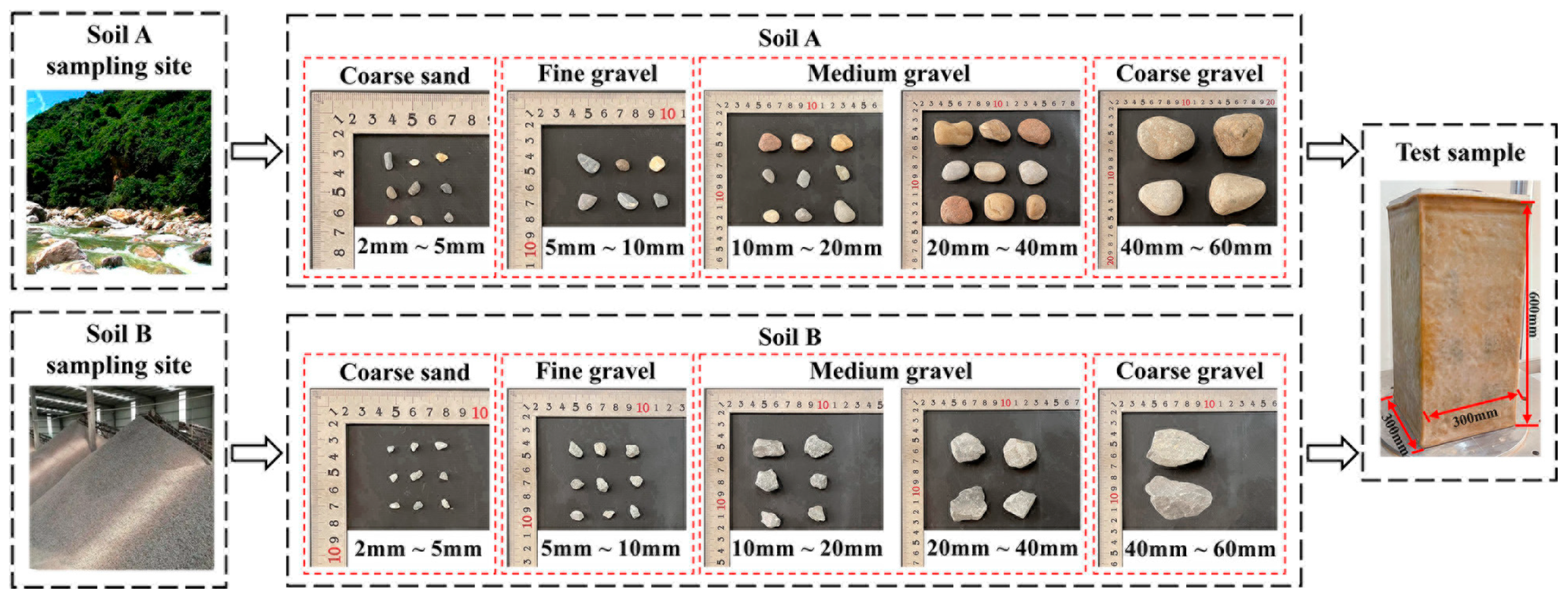
Two types of coarse-grained soil were collected from FengHe River beach in Shaanxi Province of China and from a certain transportation engineering unit; these were referred to as Soil A and Soil B, respectively. Soil A consisted of well-rounded gravel with a particle size range of 2 mm to 60 mm. Soil B contained angular gravel with a particle size range of 2 mm to 60 mm. The specific physical parameters are listed in Table 1. The test specimens were rectangular with dimensions of 300 mm length, 300 mm width, and 600 mm height. The coarse-grained soil and samples used for testing are shown in Figure 1.

Table 1.
Physical parameters of coarse-grained soil.
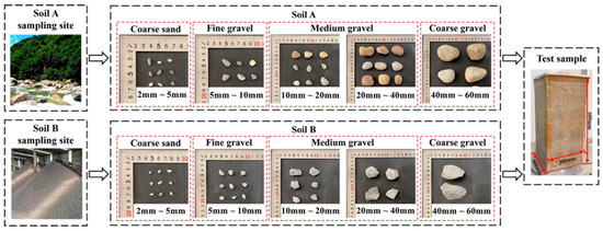
Figure 1.
Sampling sites for the two types of coarse-grained soil, soil samples with different particle sizes, and test samples.
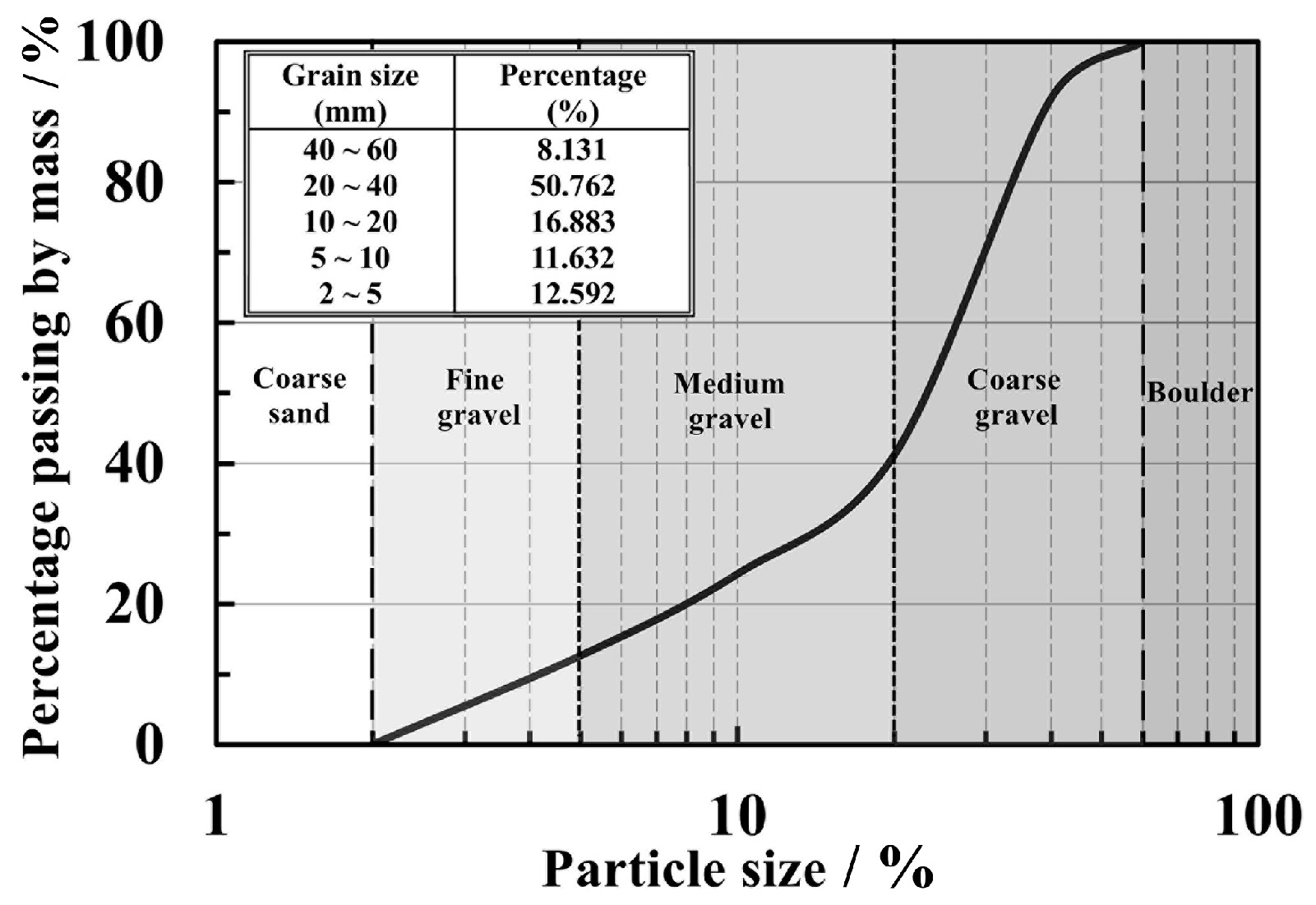
Both types of coarse-grained soil specimens were equally well graded. The grading curve is shown in Figure 2. The curvature coefficient (Cc) was 1.49, and the uniformity coefficient (Cu) was 6.26, categorizing the gravel as well-graded gravel (GW) according to engineering classification [32].
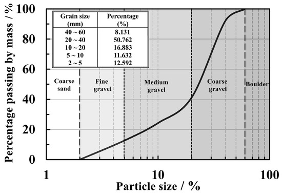
Figure 2.
The grading curve of coarse-grained soil samples.
2.2. The Test Instruments and Plans
The planar strain testing apparatus was modified from a large-scale true triaxial device [33]. Using this apparatus, vertical loading is achieved via rigid bidirectional symmetric loading, and the horizontal confinement pressure is applied using flexible hydraulic latex capsules. The modification for planar strain in the pressure chamber involved the use of a pair of smooth steel plates instead of a pair of radial hydraulic bags. Behind each steel plate, there are six pressure sensors, and bolts mounted on the pressure sensors can control the distance between the steel plate and the inner wall of the pressure chamber. This enables the specimen to be maintained in a planar strain state while lateral confinement pressure is also applied. The modified planar strain pressure chamber is depicted in Figure 3. The test included confinement pressures of 100 kPa, 200 kPa, 300 kPa, and 400 kPa, with a vertical loading rate of 0.6 mm/min [32]. The vertical strain was loaded to levels of 0.5%, 1%, 3%, 6%, and 10%; after each of these levels was attained, the vertical stress began to unload at a rate of 0.06 mm/min [31]; this was followed by reloading until the confinement pressure was reached. The test was stopped when the vertical strain reached 15% [32].
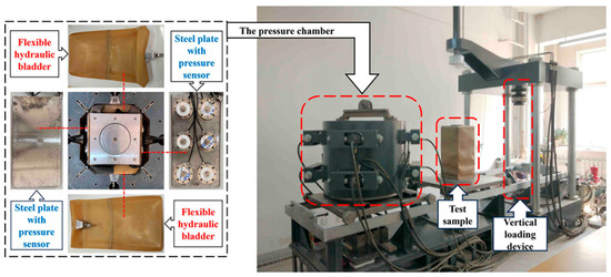
Figure 3.
The large-scale true triaxial instrument and plane strain chamber.
3. Test Results and Discussion
3.1. The Volumetric Strain
Figure 4 illustrates the relationship between the εv (volumetric strain) and ε1 (axial strain) on coarse-grained soil during the plane strain cyclic loading–unloading shear test. The volumetric strains on both types of coarse-grained soils exhibit characteristics of shear contraction followed by shear dilation. Soil A exhibits evident shear dilation at lower confining pressures, but this dilation diminishes as the confining pressure increases, although it tends to shift back to dilation with increased vertical strain. Soil B only exhibits noticeable shear dilation at 100 kPa, with shear contraction deformation at other confining pressures. It can also be observed that Soil A—with better roundness and a smaller void ratio—exhibits more pronounced shear dilation than Soil B. With a constant vertical loading rate, greater lateral dilation means that shear dilation is more likely to occur. Because the particles of Soil A are rounder and the sample has fewer voids under compression and shear, both intact and broken soil particles are more likely to move laterally in the direction of the lower confining stress, resulting in more significant lateral dilation. In contrast, Soil B, with its poorer particle roundness, exhibits more evident particle interlocking. This makes particle sliding more challenging, and the larger voids in the sample mean that both intact and broken particles are more likely to fill these internal voids, resulting in smaller lateral dilation.
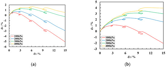
Figure 4.
Cyclic loading–unloading εv-ε1 curves for coarse-grained soil of the following types: (a) Soil A and (b) Soil B.
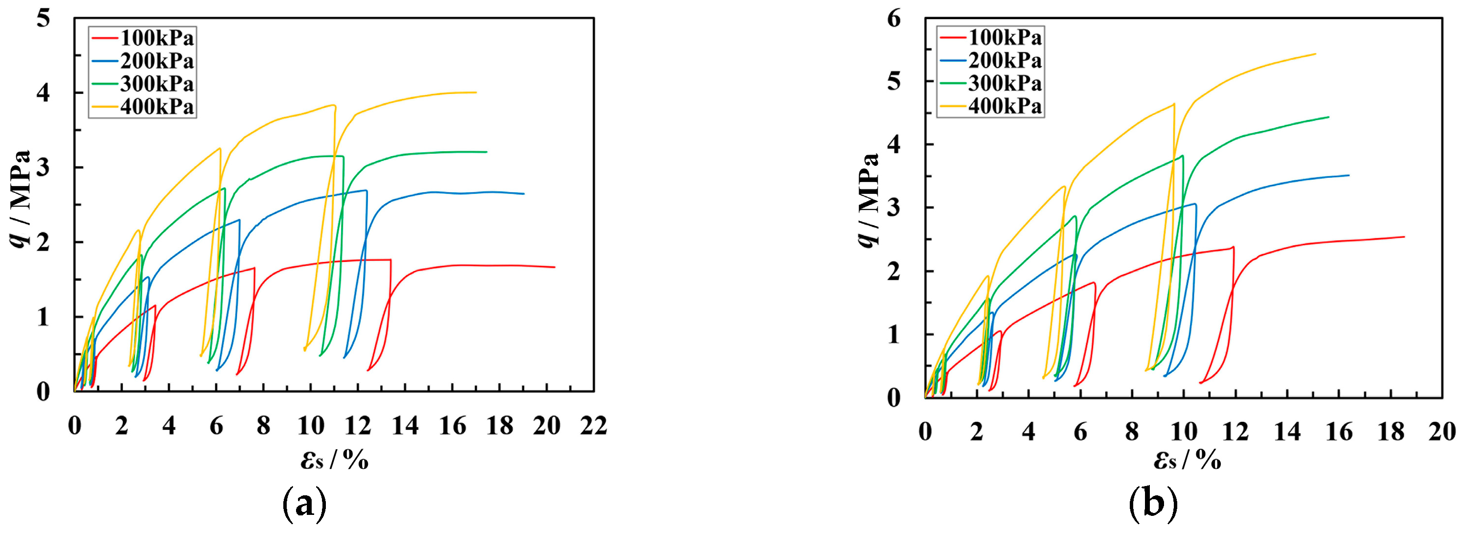
3.2. The Shear Stress–Strain Behavior
Figure 5 depicts the curves for the relationships between the q (generalized shear stress) and εs (generalized shear strain) during the cyclic loading–unloading tests for the two types of coarse-grained soils. The unloading and reloading segments of the q-εs curve form a hysteresis loop. The Δεs (generalized shear strain unloading rebound deformation) at the beginning of unloading is minimal but rapidly increases as q continually decreases. A higher stress level leads to a larger rebound, resulting in a larger area enclosed by the hysteresis loop. The q-ε1 curve for coarse-grained Soil A generally shows weak hardening, whereas the curve for Soil B consistently indicates strong hardening. The peak shear stress for Soil A is lower than that for Soil B. Soil A has a lower particle strength, making it more prone to brittle particle fracturing under vertical stress. Additionally, as described in the previous section, Soil B exhibits more significant shear contraction deformation, more pronounced compressive hardening, and a higher peak shear stress.

Figure 5.
Cyclic loading–unloading q–εs curves for coarse-grained soil of the following types: (a) Soil A and (b) Soil B.
3.3. Modulus in Cyclic Loading–Unloading Stress Path
In finite element simulations and constitutive modeling calculations, it is necessary to select appropriate material parameters to ensure the accuracy of the calculations. For coarse-grained soils, during multiple unloading–reloading cycles, phenomena such as repeated changes in particle arrangement and particle fragmentation must be considered. These factors result in mechanical properties of coarse-grained soils that differ from those obtained using monotonic loading tests.
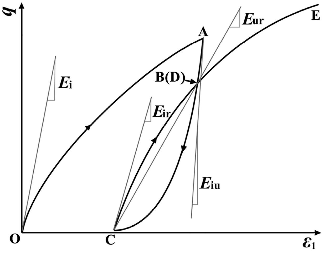
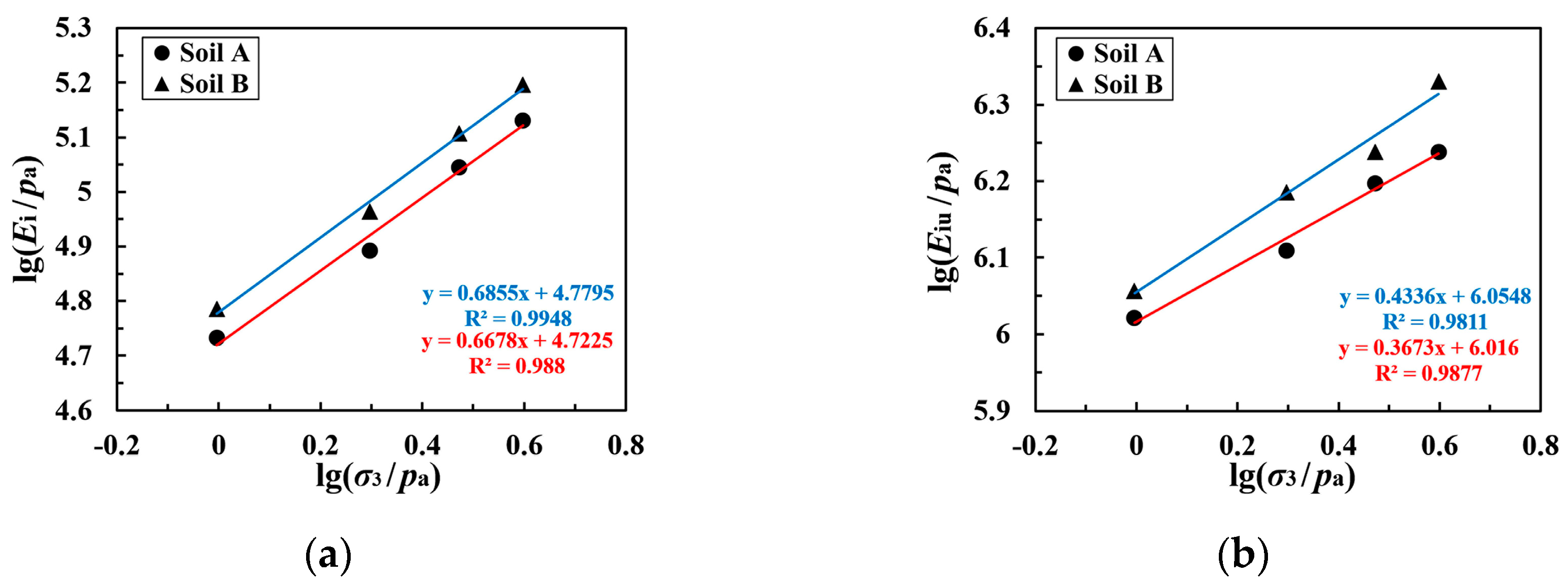
Figure 6 illustrates the moduli in cyclic loading–unloading tests. It can be seen that the Ei (initial tangent modulus) corresponds to the tangent modulus during the first loading segment (segment OA in Figure 6); the Eiu (initial unloading modulus) represents the tangent modulus during various unloading segments in the cyclic loading–unloading test (segments AC in Figure 6); Eir denotes the initial reloading modulus during various reloading segments (segments CD in Figure 6); and the Eur (unloading–reloading modulus) corresponds to the slope of the line connecting the two intersection points of the hysteresis loop (points B and C in Figure 6). The stress level S at each unloading point is calculated using Equation (1), and the variations in Eiu, Eir, and Eur for both coarse-grained soils under different confining pressures with S are shown in Figure 7 and Figure 8, respectively.
where qul is the generalized shear stress at the unloading point (kPa), and qf is the peak generalized shear stress (kPa).

Figure 6.
Schematic diagram of each modulus in the cyclic loading–unloading stress path.
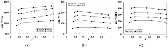
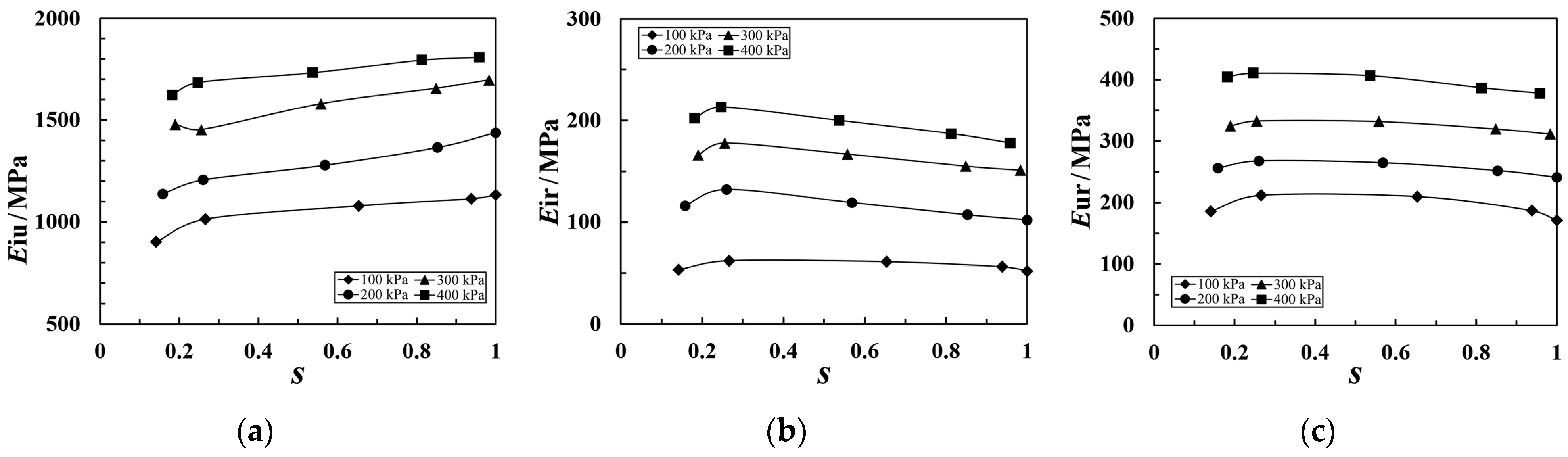
Figure 7.
Relationship between modulus and S for Soil A with different moduli of (a) Eiu, (b) Eir, and (c) Eur.
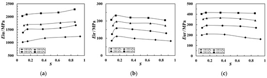
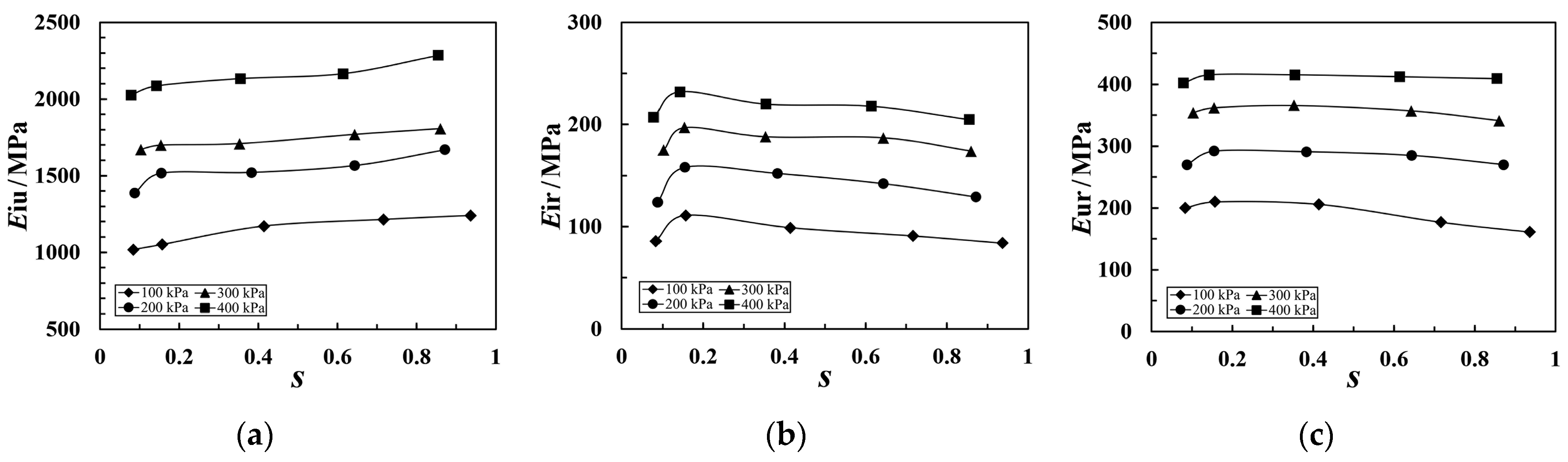
Figure 8.
Relationship between modulus and S for Soil B with different moduli of (a) Eiu, (b) Eir, and (c) Eur.
As can be seen from Figure 7 and Figure 8, the moduli of coarse-grained soil change with the stress level during cyclic loading–unloading tests. Both Eir and Eur initially increase and then decrease as S rises, and the peak value declines when the stress level is between 0.15 and 0.25. At lower stress levels, the specimen primarily undergoes compaction. The structural readjustment caused by unloading results in an increase in particle contacts, enhancing the specimen’s stiffness and causing a slight rise in Eir and Eur. As the stress level rapidly increases, soil particles are more prone to breaking. The broken particles have lower strength than the intact ones and repeated reloading weakens particle strength, leading to a decrease in Eir and Eur. In contrast, Eiu increases with the rise in S. This is due to the cumulative increase in plastic strain from repeated unloading–reloading and particle fracturing, reducing the instantaneous vertical strain rebound upon unloading. The change in each modulus with stress level at a constant confining pressure is relatively minor; an average value can thus be taken as the modulus for that level of confining pressure. Values for the four moduli obtained from the plane strain cyclic loading–unloading tests for coarse-grained soil are summarized in Table 2.
Table 2.
Modulus values for coarse-grained soil.
As can be seen in Table 2, values of all four moduli for the coarse-grained soil increase with the rise in confining pressure. Under different confining pressures, Soil B, which has higher strength, exhibits consistently higher modulus values compared with coarse-grained Soil A. At low confining pressures, Eir is slightly less than Ei. As the confining pressure increases, Eir gradually approaches Ei, with only a minor difference between them. Thus, in calculations, Ei can be used as an approximation for Eir. The Eur values for the two coarse-grained soil samples with consistent gradation show a small difference. However, Eiu is significantly higher than the other three moduli. Therefore, when calculating the unloading deformation, this modulus should be used separately to ensure accuracy.
The Janbu empirical equation, expressed as in Equation (2), describes the relationship between the modulus and the confining pressure.
where E is the modulus (kPa), K and n are modulus parameters, and Pa is the atmospheric pressure (kPa).
Taking the logarithm of both sides of Equation (2) yields Equation (3).
In Equations (2) and (3), E can be taken as any of the four moduli, Ei, Eiu, Eir, and Eur, from the coarse-grained soil cyclic loading–unloading test. The fitting relationship between these four moduli and the confining pressure is illustrated by the curves in Figure 9.


Figure 9.
The fitting curves of the relationship between modulus and S for the two types of coarse-grained soil with different moduli of (a) Ei, (b) Eiu, (c) Eir, and (d) Eur.
As can be seen in Figure 9, lg(Ei/pa), lg(Eiu/pa), lg(Eir/pa), and lg(Eur/pa) each exhibit a linear relationship with lg(σ3/pa). We may say, therefore, that Equation (2) can reasonably predict the various moduli of coarse-grained soil under different confining pressure conditions in unload–reload tests. The parameters of the various moduli for the two types of coarse-grained soil are presented in Table 3.
Table 3.
The modulus parameters of coarse-grained soil.
4. A Cyclic Loading–Unloading Constitutive Model
4.1. The Idea of Establishing the Model
In Figure 10, point D on the reloading segment CF coincides with the unloading point B, with both points having the same stress qα and strain εα. Upon reloading to point E, the stress qβ matches that at point A, but the strain εγ at point E is greater than the strain εβ at point A. Conventional plasticity theory suggests that the position of the yield surface is related only to the historical maximum stress qmax and not to the stress path [34]. As depicted in Figure 11, during unloading, the yield surface contracts from A to C. The reduction in stress level causes soil particles to rebound and the particle fabric to redistribute. Upon reloading, the stress increment dσ on the yield surface of point C, directed outward, results in new plastic strains. Consequently, points A and E in Figure 10 do not coincide, and so it is not entirely appropriate to consider segment CE as merely nonlinear elastic deformation. Both the initial loading and reloading deformations should be treated as elastoplastic deformations. For the present study, therefore, we employed a combined theory of elastoplasticity and nonlinear elasticity to establish a constitutive model for the unloading–reloading of coarse-grained soil under plane strain conditions.
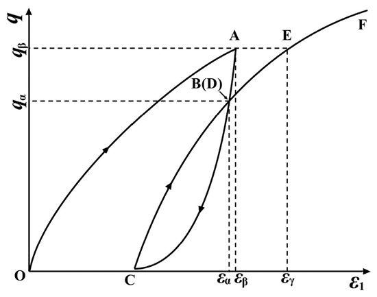
Figure 10.
Schematic diagram of stress–strain relationship in cyclic loading–unloading test.
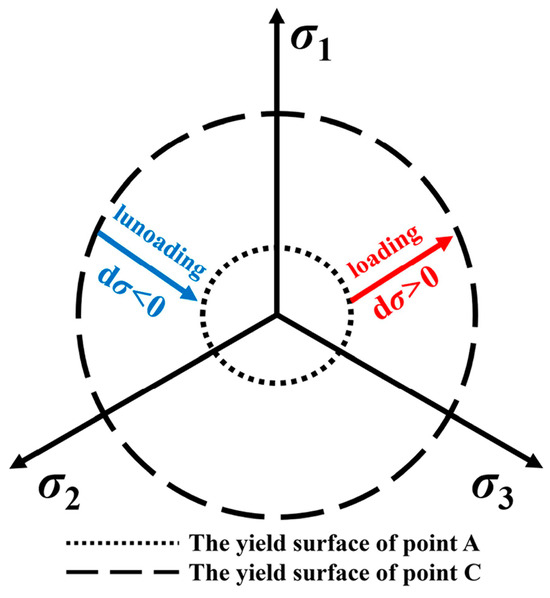
Figure 11.
Schematic diagram of the yield surface in principal stress space.
4.2. The Loading (Reloading) Constitutive Model
As described in Section 4.1, the deformation in each loading phase of the cyclic loading–unloading test is elastoplastic deformation. Because coarse-grained soil is mainly composed of non-cohesive coarse particles, the Lade–Duncan model based on sandy soil may be considered more suitable to describe the stress–strain relationship during the loading phase. According to the concept of the elastoplastic constitutive model, the total strain increment can be obtained by summing the elastic strain increment and the plastic strain increment, as Equation (4).
where represents the total strain increment, represents the elastic strain increment, and represents the plastic strain increment.
The yield function, flow rule function, and hardening law function of the Lade–Duncan model are shown in Equations (5)–(7), respectively.
where I1 is the first invariant of the stress tensor, I3 is the third invariant of the stress tensor, and k is the hardening parameter.
where k1 is the plastic potential parameter.
where Wp is the plastic work.
4.2.1. Elastic Strain of the Loading Section
The elastic strain during loading is calculated using the generalized Hooke’s law:
where ν is the Poisson’s ratio, and E is the initial tangent modulus for the loading segment (MPa).
In Equation (8), the value of E for the initial loading segment is taken as Ei; for the reloading segment, it is taken as Eir. As can be seen from Table 2, the difference between Ei and Eir is small. To simplify calculations, E can be approximated as Ei. In the state of plane strain, , Equation (8) can now be simplified as Equation (9).
4.2.2. The Hardening Parameter k and Plastic Work Wp
The plastic work is chosen as the hardening parameter in the hardening law; k and Wp have a hyperbolic relationship [34].
where kt is a value slightly greater than 27, a is the reciprocal of the initial slope of the hyperbola, and b is the asymptote of (k − kt) when Wp approaches positive infinity.
The value of a is related to the confining pressure and can be obtained by using Equation (11).
where m and l are dimensionless parameters.
Experimental results indicated that when the confining pressure is the same, the a values for each reloading segment are not significantly different and can be taken as an average value denoted as arl, with parameters mrl and lrl. However, the a value for the initial loading segment is different from that of the reloading segments and should be considered separately, being denoted as ail, with parameters mil and lil.
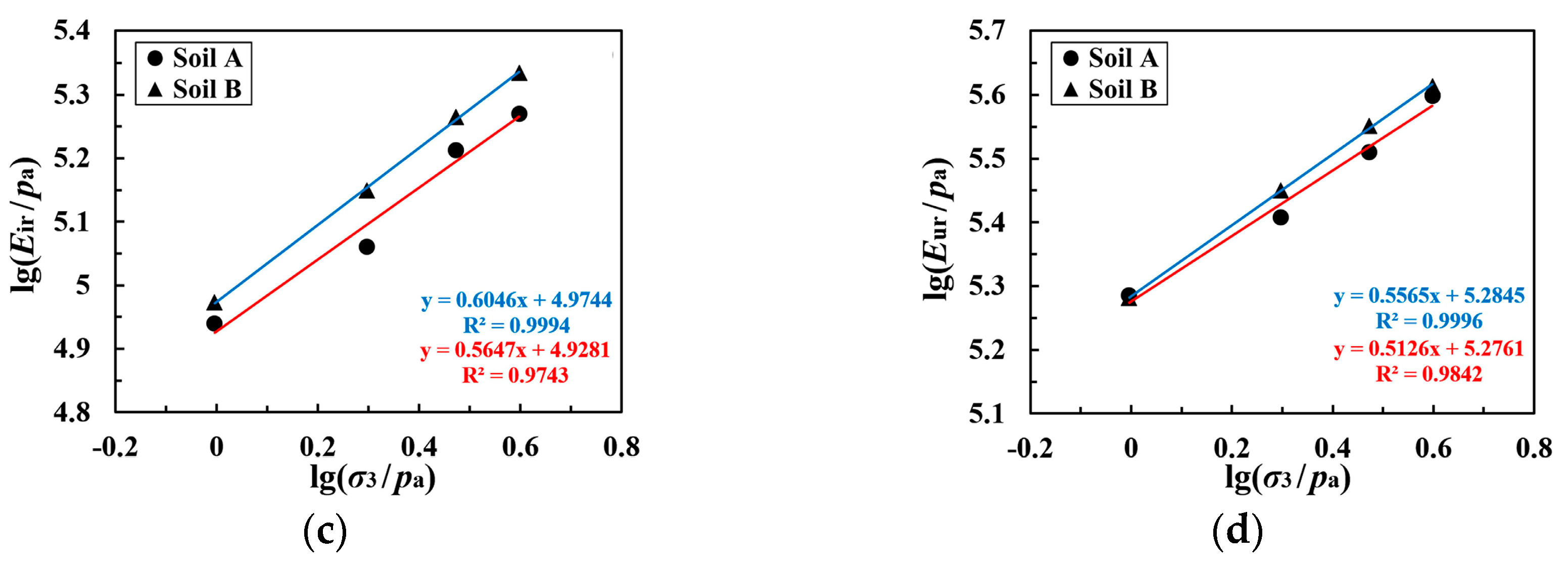
The parameter b is related to the stress level S at the start point of unloading, and there is a power function relationship between them, as shown in Figure 12. This can be calculated using Equation (12).
where D is a parameter related to the consolidation pressure; this can be calculated by Equation (13).
where c, d, and f are all dimensionless parameters.
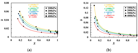
Figure 12.
The fitting curve of the relationship between b and S for coarse-grained soil of the following types: (a) Soil A and (b) Soil B.
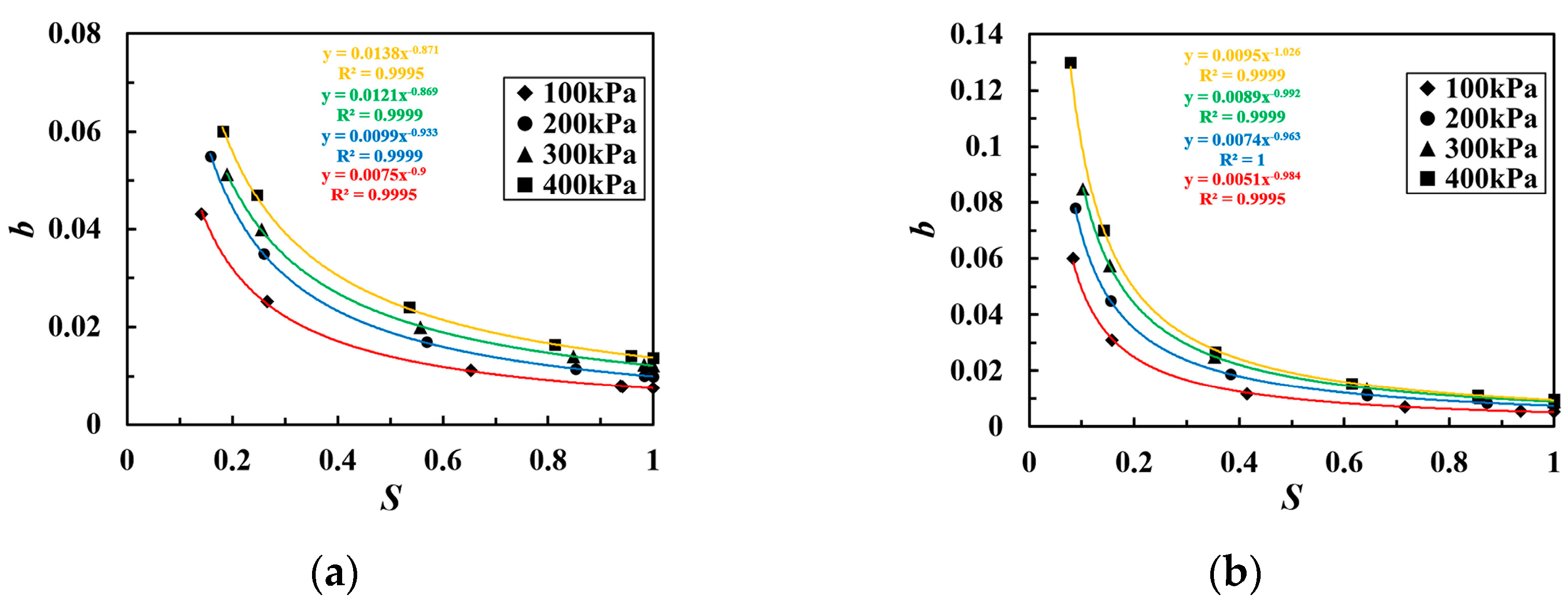
Taking the logarithm on both sides of Equation (12), we can obtain Equation (14). The fitting relationship between lg b and lg S is shown in Figure 13, where they have a relatively good linear relationship.
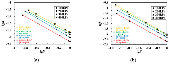
Figure 13.
The fitting curve of the relationship between lgb and lgS for coarse-grained soil of the following types: (a) Soil A and (b) Soil B.
Similarly, taking the logarithm on both sides of Equation (13), we can obtain Equation (15).
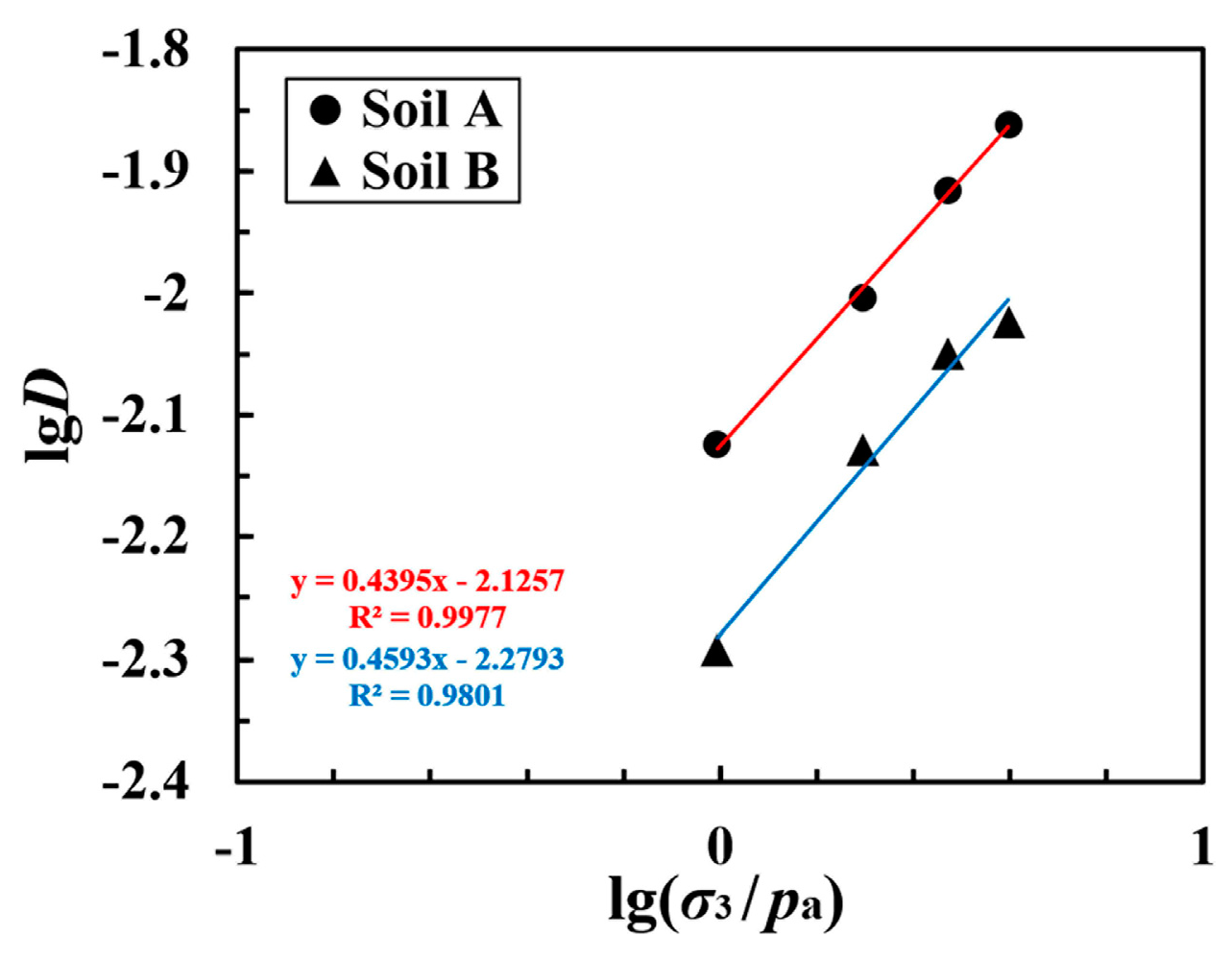
The relationship between lgD and lg(σ3/Pa) is shown in Figure 14; here, again, a relatively good linear relationship can be seen.

Figure 14.
The fitting curve of the relationship between lgD and lg(σ3/Pa).
By substituting Equation (15) into Equation (14), the parameter b can be calculated. The plastic work Wp can be calculated using Equation (16).
Differentiating Equation (16) yields Equation (17).
where p is the average principal stress (kPa), is the plastic volumetric strain, and is the plastic generalized shear strain.
4.2.3. The Correction of Plastic Potential Parameter k1
The plastic potential parameters can be indirectly obtained from the plastic dilatancy ratio vp, which is defined in Equation (18).
where and represent the increments of plastic strain in the vertical and confining pressure directions, respectively.
The Lade–Duncan model is based on conventional triaxial tests, where σ2 = σ3; however, under plane strain or true triaxial three-dimensional stress conditions, σ2 ≠ σ3. Therefore, and need to be corrected and calculated via Equation (19).
Substituting Equation (19) into Equation (18) yields Equation (20), from which k1 can be obtained.
4.2.4. The Plastic Multiplier dλ
From Equation (6), it is known that the flow rule g is a third-order homogeneous equation with respect to σij. Therefore, Equation (17) can also be expressed as Equation (21) using Euler’s theorem.
Differentiating Equation (10) and substituting it into Equation (18) yields Equation (22), from which dλ is obtained.
Substituting Equation (22) into Equation (19) results in Equation (23), which allows for the calculation of the increments in plastic strain.
In summary, the loading segment constitutive model parameters included are Ki, ni, v, mrl, lrl, mil, lil, c, d, and f, i.e., a total of 10 parameters.
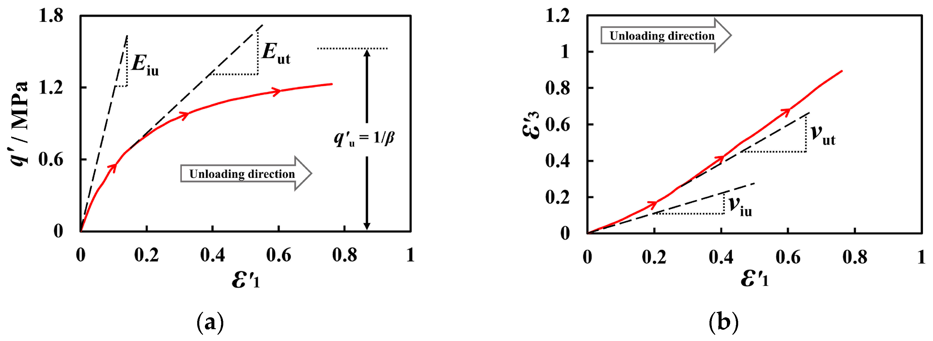
4.3. The Unloading Constitutive Model
In line with the development approach of the unloading–reloading constitutive model, a nonlinear elastic model was utilized to describe the nonlinear deformation of coarse-grained soil during substantial unloading. Taking the fifth unloading section of the cyclic loading–unloading test for Soil A at a confining pressure of 100 kPa as an example, as depicted in Figure 15, the q-ε1 and ε3-ε1 curves in the unloading test resemble hyperbolas. However, the starting point of unloading does not lie at the origin of the stress–strain spatial coordinate system. Therefore, a coordinate system transformation is applied to the old coordinate systems of the q-ε1 and ε3-ε1 curves. Via this transformation, a corrected E-v model is established to define the unloading constitutive relationship. The curves of and after coordinate transformation are shown in Figure 16.
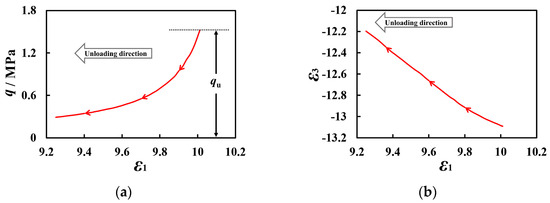
Figure 15.
The unloading stress–strain curves in the original coordinate system with types of (a) q-ε1 and (b) ε3-ε1. (The red arrow line represents the unloading curve and direction).
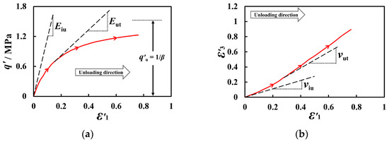
Figure 16.
The unloading stress–strain curves in the new coordinate system with types of (a) and (b) . (The red arrow line represents the unloading curve and direction).
4.3.1. The Unloading Tangent Modulus (Eut)
The Eut may be defined as Equation (24).
The curve in the new coordinate system can be described using Equation (25).
where α and β are the model parameters, which can be obtained from Equation (26).
where Eiu is the initial unloading modulus, and is the ultimate unloading strength in the new coordinate system.
As can be seen from Figure 5, the unloading limit strength tends to approach zero in the original coordinate system. Therefore, in the new coordinate system, the value of the curve can be taken as the q value of the initial unloading point. When calculating the unloading tangent modulus, the unloading limit strength can be directly obtained from the experiment, and thus only two parameters, Kiu and niu, are needed.
After differentiating Equation (25), Equation (27) can be obtained.
By substituting Equations (26) and (27) into Equation (24), Etu can be calculated by Equation (28).
4.3.2. The Unloading Tangent Poisson’s Ratio (νtu)
As shown in Figure 16b, the unloading tangent Poisson’s ratio (νtu) may be defined as Equation (29).
The curve in the new coordinate system can be described by Equation (30).
where fu and Du are model parameters.
Different values of fu and Du can be obtained under different confining pressure conditions. fu can be calculated using Equation (31), and Du values—which are relatively close under different confining pressures—can be averaged.
By differentiating Equation (30), Equation (32) can be obtained.
Substituting Equations (31) and (32) into Equation (29), νut can be calculated by Equation (33).
The Etu-νtu unloading constitutive model includes Kiu, niu, Gu, Fu, and Du, i.e., a total of five model parameters. This is three fewer than the eight parameters in the E-v model, making the calculation more straightforward.
5. Validation of the Model
According to the cyclic loading–unloading constitutive model, the model parameters for Soil A and Soil B are listed in Table 4.
Table 4.
The model parameters of coarse-grained soil.
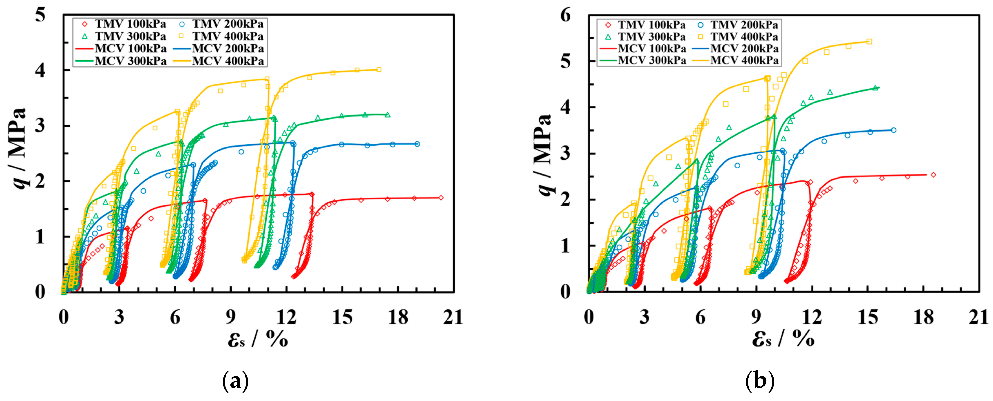
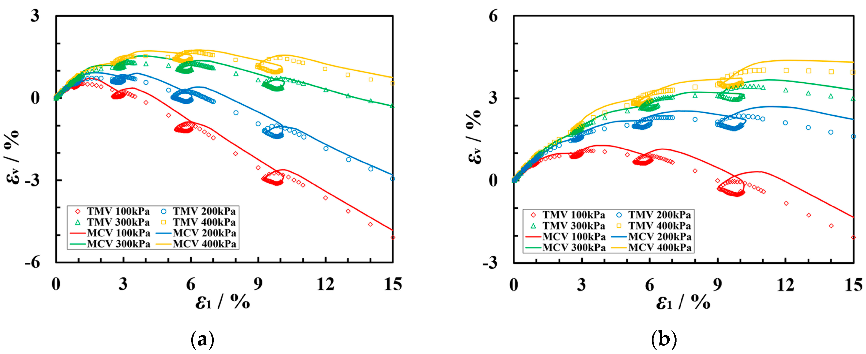
The comparison between test measurement values (TMVs) and model calculations values (MCVs) of the q-εs and εv-ε1 curves for the two types of coarse-grained soils is shown in Figure 17 and Figure 18. This constitutive model can reasonably predict the stress–strain relationship of coarse-grained soils under plane strain cyclic loading–unloading conditions.
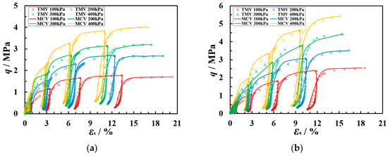
Figure 17.
The q-εs curves of TMVs and MCVs for coarse-grained soil of the following types: (a) Soil A and (b) Soil B.
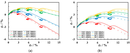
Figure 18.
The εv-ε1 curves of TMVs and MCVs for coarse-grained soil of the following types: (a) Soil A and (b) Soil B.
6. Conclusions
In the plane strain cyclic loading–unloading test, the more rounded the particles of the coarse-grained soil and the smaller the porosity, the more pronounced the dilative behavior. An increase in confining pressure restricts lateral expansion, reducing dilatancy. The strength of the parent rock is also a factor influencing the peak shear stress and the shape of the stress–strain curve. The greater the strength of the parent rock, the higher the peak shear stress, with the stress–strain curve exhibiting a more pronounced hardening behavior.
Under the same confining pressure conditions, both the Eir and the Eur initially increase and then decrease as the stress level and the number of unloading–reloading cycles increase. However, the initial reloading modulus Eiu continuously increases, and the moduli for Soil B are all greater than those for Soil A. All four moduli increase with an increase in confining pressure and exhibit a linear relationship with confining pressure on a logarithmic scale. At consistent confining pressures, Eir is slightly greater than the initial tangent modulus Ei. Eur is significantly greater than both Ei and Eir, while Eiu is much larger than the other three moduli. When calculating significant unloading deformations, Eiu should be used to ensure accuracy.
Modifications were made to the Lade–Duncan model’s plastic potential parameter k1 for three-dimensional stress conditions, establishing a loading (reloading) model. After introducing the initial unloading modulus, coordinate system transformations were applied to correct the E-v model, establishing the Etu-νtu unloading model. Consequently, a combined 15-parameter cyclic loading–unloading constitutive model under plane strain conditions was established. The physical meanings of the model parameters are clear, making it convenient for application in calculating complex stress path tests involving unloading–reloading. Comparisons between the model’s calculated values and experimental values indicate that the model’s predictions are relatively accurate.
Author Contributions
Investigation, Z.W.; methodology, S.S. (Shengjun Shao); writing—original draft, Z.W.; writing—review and editing, S.S. (Shuai Shao) and L.Y.; data curation, Z.W. and L.Y.; funding acquisition, S.S. (Shuai Shao) and S.S. (Shengjun Shao). All authors have read and agreed to the published version of the manuscript.
Funding
This research was supported by the National Natural Science Foundation of China (52108342), Basic Research Program of Natural Science in Shaanxi Province-Han-Wei Joint Found Project (2019JLP-21, 2021JLM-50), Shaanxi Water Science and Technology Program Project (2021slkj-12), Doctoral initial funding of Xi’an University of Technology (107-451122001).
Data Availability Statement
The experimental data supporting the conclusions are available from the corresponding author and senior author upon request.
Conflicts of Interest
The authors declare no conflicts of interest.
References
- Zhai, Q.; Rahardjo, H.; Satyanaga, A.; Dai, G. Estimation of the soil-water characteristic curve from the grain size distribution of coarse-grained soils. Eng. Geol. 2020, 267, 105502. [Google Scholar] [CrossRef]
- Wang, S.Y.; Zhan, Y.J.; Qu, T.M.; Qiu, T.; Wang, H.B. Effect of Gradation on Undrained Compressibility of Foam-Conditioned Coarse-Grained Soils. Int. J. Geomech. 2023, 23, 04023089. [Google Scholar] [CrossRef]
- Guo, Q.G. Engineering Characteristics and Application of Coarse-Grained Soil; The Yellow River Water Conservancy Press: Zhengzhou, China, 1998. [Google Scholar]
- Pan, X.D.; Hudson, J.A. Plane strain analysis in modelling three-dimensional tunnel excavations. Int. J. Rock Mech. Min. 1988, 25, 331–337. [Google Scholar] [CrossRef]
- Guo, H.J.; Ji, M.; Zhao, W.S. Roadway support design based on in-situ stress and its asymmetrical distributions in a coal mine. Arch. Min. Sci. 2020, 65, 299–315. [Google Scholar]
- Zhang, C.P.; Han, K.H. Collapsed shape of shallow unlined tunnels based on functional catastrophe theory. Math. Probl. Eng. 2015, 2015, 681257. [Google Scholar] [CrossRef]
- Wilson, D.W.; Abbo, A.J.; Sloan, S.W.; Yamamoto, K. Undrained stability of rectangular tunnels where shear strength increases linearly with depth. Can. Geotech. J. 2017, 54, 469–480. [Google Scholar] [CrossRef]
- Huang, M.S.; Wang, H.Y.; Yu, J.; Tang, Z. Undrained stability analysis of a plane strain circular tunnel using streamline velocity fields. Int. J. Geomech. 2019, 19, 1–7. [Google Scholar] [CrossRef]
- Zlatanović, E.; Trajković-Milenković, M.; Lukić, D.; Brčić, S.; Šešov, V. A comparison of linear and nonlinear seismic tunnel-ground interaction analyses. Acta Geotech. Slov. 2016, 13, 27–42. [Google Scholar]
- Shi, W.C.; Zhu, J.G.; Zhang, B.; Yu, T. Strength characteristics of coarse-grained soil under plane strain condition. Chin. J. Geotech. Eng. 2011, 33, 1974–1979. [Google Scholar]
- Shi, W.C.; Zhu, J.G.; Zhang, K.Y.; Yu, T. Experimental study of deformation characteristics of coarse-grained soil under plane strain condition. Rock Soil Mech. 2013, 34, 101–108. [Google Scholar]
- Lu, D.C.; Du, X.L.; Zhou, A.N.; Yao, Y.P. The principal stresses of soil mass in the direction of plane strain. Adv. Mater. Res. 2011, 243–249, 2657–2665. [Google Scholar] [CrossRef]
- Pan, J.J.; Jiang, J.W.; Cheng, Z.L.; Xu, H.; Zuo, Y.Z. Large-Scale True Triaxial Test on Stress-Strain and Strength Properties of Rockfill. Int. J. Geomech. 2020, 20. [Google Scholar] [CrossRef]
- Jiang, J.W.; Pan, J.J.; Cheng, Z.L.; Xu, H.; Tan, F. Experimental Study on the Applicability of Failure Criteria for Rockfill in Three-Dimensional Stress Conditions. Int. J. Geomech. 2021, 21. [Google Scholar] [CrossRef]
- Liu, W.; Liang, J.W.; Xu, T. Tunnelling-induced ground deformation subjected to the behavior of tail grouting materials. Tunn. Undergr. Space Technol. 2023, 140, 105253. [Google Scholar] [CrossRef]
- Dong, C.L.; Zhao, G.M.; Lu, X.Y.; Meng, X.R.; Li, Y.M.; Cheng, X. Similar simulation device for unloading effect of deep roadway excavation and its application. J. Mt. Sci.-Engl. 2018, 15, 1115–1128. [Google Scholar]
- Sun, Y.G.; Gao, Y.F.; Liu, J.M.; Cao, J.T.; Huang, S.J. Experimental study on the softening of saturated clay of zhuhai tunnel under cyclic loading. J. Yangtze River Sci. Res. Inst. 2014, 31, 52–55. [Google Scholar]
- Zhang, Y.W.; Xie, Y.L.; Weng, M.S. Centrifugal test on influence of asymmetric foundation excavation to an underlying subway tunnel. Rock Soil Mech. 2018, 39, 2555–2562. [Google Scholar]
- Ji, F.; Shi, Y.; Li, R.; Zhou, H.; Wang, D.; Zhang, J. Progressive geomorphic evolution of reservoir bank in coarse-grained soil in East China–Insights from long-term observations and physical model test. Eng. Geol. 2021, 281, 105966. [Google Scholar] [CrossRef]
- Zhu, J.G.; Wang, Y.L.; Jia, H.; Zhang, B. Experimental study on resilience behaviour of coarse-grained soils. Chin. J. Geotech. Eng. 2011, 33, 950–954. [Google Scholar]
- Chu, F.Y.; Zhu, J.G.; Jia, H.; An, S.H. Experimental study of mechanical behaviour of coarse-grained soil in unloading and reloading. Rock Soil Mech. 2012, 33, 1061–1066. [Google Scholar]
- Yu, H.; Shen, X.M.; Ye, Y.C.; Yang, J.; Zhu, C.H. Large-scale triaxial tests on dilatancy characteristics of lean cemented sand and gravel. Front. Earth Sci. 2021, 9, 799215. [Google Scholar] [CrossRef]
- Zhang, P.F.; Liu, H.; Feng, Z.T.; Jia, C.F.; Zhou, R. A constitutive model of sandy gravel soil under large-sized loading/unloading triaxial tests. Adv. Civ. Eng. 2021, 7, 4998351. [Google Scholar] [CrossRef]
- Ling, H.; Chen, S.S.; Zhai, Y.C.; Fu, H.; Shi, B.X. Experimental study on strength and deformation of filling materials of super-high dams with wide confining pressures under loading and unloading conditions. Chin. J. Geotech. Eng. 2021, 43, 27–33. [Google Scholar]
- Wang, Y.M.; Wang, Y.Q.; Luo, S.; Liu, H.; Yi, G.S.; Peng, K. Influence of the Crack Angle on the Deformation and Failure Characteristics of Sandstone under Stepped Cyclic Uniaxial Compression with a Constant Lower Limit. Mathematics 2023, 11, 2187. [Google Scholar] [CrossRef]
- Long, Y.; Sun, L.; Cai, Z.; Jiang, Z.; Wang, Z.; He, Q.; Bai, Z. Cyclic Loading and Unloading of Weakly Consolidated Sandstone with Various Water Contents. Sustainability 2023, 15, 13866. [Google Scholar] [CrossRef]
- Tao, Z.F.; Wang, Z.Y.; Ling, J.M.; Tian, Y.; Cai, J.W.; Shi, R. Anisotropic resilient modulus model of granular materials based on particle characteristics. Transp. Res. Rec. 2021, 2675, 970–984. [Google Scholar] [CrossRef]
- Wang, Y.; Du, W.; Zhang, D.; Yu, B. Effect of Loading and Unloading Rates on Sandstone Deformation and Dilatancy under True Triaxial Condition. Sustainability 2023, 15, 5105. [Google Scholar] [CrossRef]
- Wang, S.; Wang, L.G.; Tian, J.S.; Fan, H.; Jiang, C.Y.; Ding, K. An experimental study on the effects of true triaxial loading and unloading stress paths on the mechanical properties of red sandstone. Minerals 2022, 12, 204. [Google Scholar] [CrossRef]
- Liu, B.H.; Kong, L.W.; Xu, G.F.; Sun, Z.L. Effects of three-dimensional cyclic stresses on permanent deformation of natural undisturbed clay. Int. J. Geomech. 2022, 12, 04022220. [Google Scholar] [CrossRef]
- Wang, Y.X.; Shao, S.J.; Wang, Z.; Liu, A.G. Experimental study on the unloading characteristics of coarse aggregate under true triaxial shear loading. Chin. J. Rock Mech. Eng. 2020, 39, 1503–1512. [Google Scholar]
- Ministry of Water Resources of the PRC. GB/T50123-2019; Standard for Geotechnical Testing Method. China Planning Press: Beijing, China, 2019.
- Shao, S.J.; Wang, Y.X.; Shao, S. A large-scale true triaxial apparatus with rigid-flexible-flexible boundary for granular materials. Geotech. Test J. 2021, 44, 1179–1196. [Google Scholar] [CrossRef]
- Zheng, Y.R.; Kong, L. Geotechnical Plastic Mechanics; China Architecture & Building Press: Beijing, China, 2010. [Google Scholar]


Disclaimer/Publisher’s Note: The statements, opinions and data contained in all publications are solely those of the individual author(s) and contributor(s) and not of MDPI and/or the editor(s). MDPI and/or the editor(s) disclaim responsibility for any injury to people or property resulting from any ideas, methods, instructions or products referred to in the content. |
© 2024 by the authors. Licensee MDPI, Basel, Switzerland. This article is an open access article distributed under the terms and conditions of the Creative Commons Attribution (CC BY) license (https://creativecommons.org/licenses/by/4.0/).