1. Introduction
Next-generation buildings need to integrate sustainability features as well as enhanced structural resilience to natural hazards like earthquakes, storm winds, floods, and tsunamis, among others. Seismic isolation is a convenient earthquake protection technique for civil buildings and infrastructures (see, e.g., the review paper [
1] and references therein), vibration-sensitive equipment in hospitals [
2], nuclear power plants [
3,
4,
5], as well as artworks in museums [
6]. In this case, a superstructure is separated from its substructure by the insertion of compliant devices (seismic isolators) that permit relative motions of the structural systems at the interface level. Elastomeric bearings [
7,
8,
9] and friction-pendulum (FP) isolators [
10] are frequently employed nowadays to design earthquake-proof structures. With this system, the fundamental periods of vibration are designed so as to avoid the resonance of the isolated building with seismic excitations, taking care to avoid the displacement drift between the superstructure and the foundation (that is, the displacement capacity of the isolation system) does not exceed suitable design limits [
11]. However, the considerably high costs and complex manufacturing processes required to install these devices limit their use in developing countries to relevant public buildings and infrastructures [
12,
13]. Some low-cost isolators have been proposed in the literature, including, among others, the replacement of confinement steel plates in rubber bearings with fiber-reinforced composites [
14], the use of recycled elastomers [
15], nanocomposite rubber [
16], composite sand–rubber layers [
17], etc. There is ongoing research into how the mechanical properties of these systems will age [
13,
18].
Seismic isolation is usually applied to low- or medium-rise multistory buildings since its efficiency and economical convenience are inversely proportional to the (effective) compliance of the superstructure, which typically grows with the height of the building [
19]. Nevertheless, interesting applications of such a technology have been proposed in the literature for tall buildings, by considering distributed isolation systems that permit the segmentation of an earthquake-resistant building along its height (refer, e.g., to [
20,
21] and references therein). Since the design displacement capacity of the isolation system grows with the number of stories of the superstructure, when the first mode of vibration dominates the seismic response of the system [
22], it is important to employ isolators that can achieve large lateral displacements for a given footprint of the isolator.
This study builds on recent research dealing with innovative and bioinspired seismic isolators, which combine sliding–stretching energy dissipation mechanisms to protect a structure from seismic waves [
23,
24]. The main goal of this line of research is to show that it is possible to build cost-effective and easily tunable seismic isolation devices that can be designed using a bioinspired approach and can be assembled from environmentally sustainable components, using ordinary 3D printers and biobased and/or recycled materials to build the non-structural parts (see, e.g., the
Nature article [
24]). The mechanical properties of these devices can be tuned by optimizing the internal architecture of the unit cell, the friction mechanisms at the interface between the terminal plates and the sliding posts, as well as by adjusting the pretension and the material of the tendons [
23]. This research is aimed at overcoming the main limitations of currently available commercial isolators, namely the employment of heavy industry for their manufacture, their limited tunability, and the inherent costs, as already observed. The bioinspiration for this study comes from animals in motion, as it has been discovered that animals tend to achieve a resonance condition between the frequency of the force produced by muscle contraction and their natural vibration frequencies, thus minimizing energy consumption [
25]. Leg and arm bones, when bent by their muscles, act like pendulums, while the presence of tendons confers a shock-absorption capacity to the locomotion system [
26,
27]. By tessellating unit cells with various architectures, the research presented in [
23] is aimed at designing bioinspired seismic “metaisolators” that are able to inverse this function: they avoid resonance between the (effective) natural frequency of the system and the excitation frequencies of earthquakes by suitably deforming the tendons in the large deformation regime. The present paper builds on the research illustrated in [
23], to show that a two-layer version of the seismic isolator formulated in the aforementioned study is able to double the displacement capacity of the device for a given footprint. Such a key result is crucial to permit the application of sliding-stretching isolators (SSI) to medium- and high-rise buildings. The structure of this paper is as follows.
Section 2 presents the adopted mechanical model of the two-layer sliding–stretching isolator (hereafter referred to as SSI2), which is obtained by suitably generalizing the one formulated in [
23] for the one-layer system (SSI1). The given model accounts for the fact that the SSI2 system is formed by two superimposed SSI1 systems that move in opposite directions.
Section 3 illustrates the results of experimental tests run on reduced-scale samples of such a device, using a dedicated shake-table setup available at the Laboratory of Structural Engineering of the University of Salerno. The fitting of the theoretical model given in
Section 2 to experimentally record the lateral force vs. lateral displacement responses is presented in
Section 4. We end in
Section 5 with concluding remarks and directions for future research.
2. Mechanical Model of the SSI2
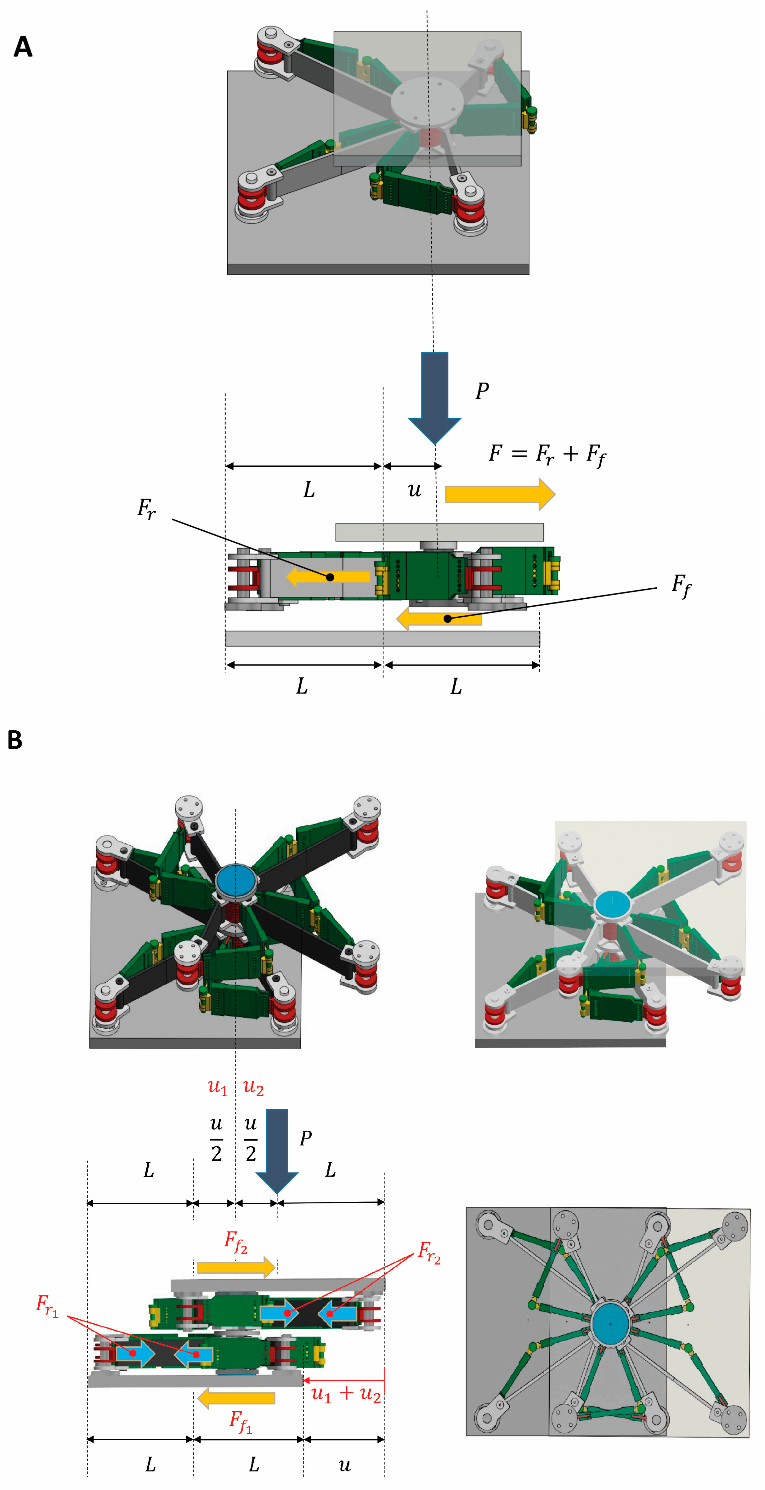
The single-layer SSI is formed by a central post that translates in solidarity with a top plate and is free to slide against a bottom plate. The top plate transmits the vertical load
applied by the superstructure, while the bottom plate is attached to the foundation (
Figure 1A). The central post is connected to four fixed corner posts through rigid and articulated “limb” members and stretchable tendons. The limbs of the device drive the motion of the central post and are connected to each other through vertical hinges (elbow and knee joints). The deformable tendons play a recentering role and dissipate energy through hysteretic pseudo-elasticity. A cap covers the central post and permits the relative rotation between the post and the top plate (the reader is referred to Ref. [
23] for further details about the SSI1 system).
This work examines a two-layer version of the SSI, which is obtained by superimposing two SSI1 unit cells, with the upper cell flipped upside down with respect to the lower cell. The central posts of such layers form a unique member, which exhibits a first sliding displacement
with respect to the bottom plate, and a second sliding displacement
with respect to the top plate. These displacements are equal in magnitude and have opposite directions, which implies that the SSI2 has a doubled displacement capacity over an SSI1 with the same footprint. Said
, the drift between the terminal plates of the SSI2,
Figure 1A,B highlights the transfer mechanisms of the
moments induced by the relative motion of the terminal plates to the foundation and the superstructure. One observes that the
moment is fully transferred to the foundation in the SSI1 (
Figure 1A), and applied half to the superstructure, and half to the foundation in the SSI2 (
Figure 1B), which marks an analogy with double-dish FP sliders [
28]. In the SSI2 system, the corner posts of the two layers transmit two equal and opposite forces
and
to the terminal plates. Here,
and
denote the restoring forces transmitted by the tendons of the bottom and top layers, respectively. Similarly,
and
respectively, denote the friction forces acting at the interfaces between the central post and the bottom and top plates (
Figure 1B). As a result, one of the two layers of the SSI2 transmits the same forces as those transmitted by an SSI1 to the superstructure and the foundation but allows a double drift between the terminal plates, as already described. It is also worth noting that the deformed configurations of each layer of the SSI2 replicate the shape of a human body with bent arms and legs (
Figure 1B).
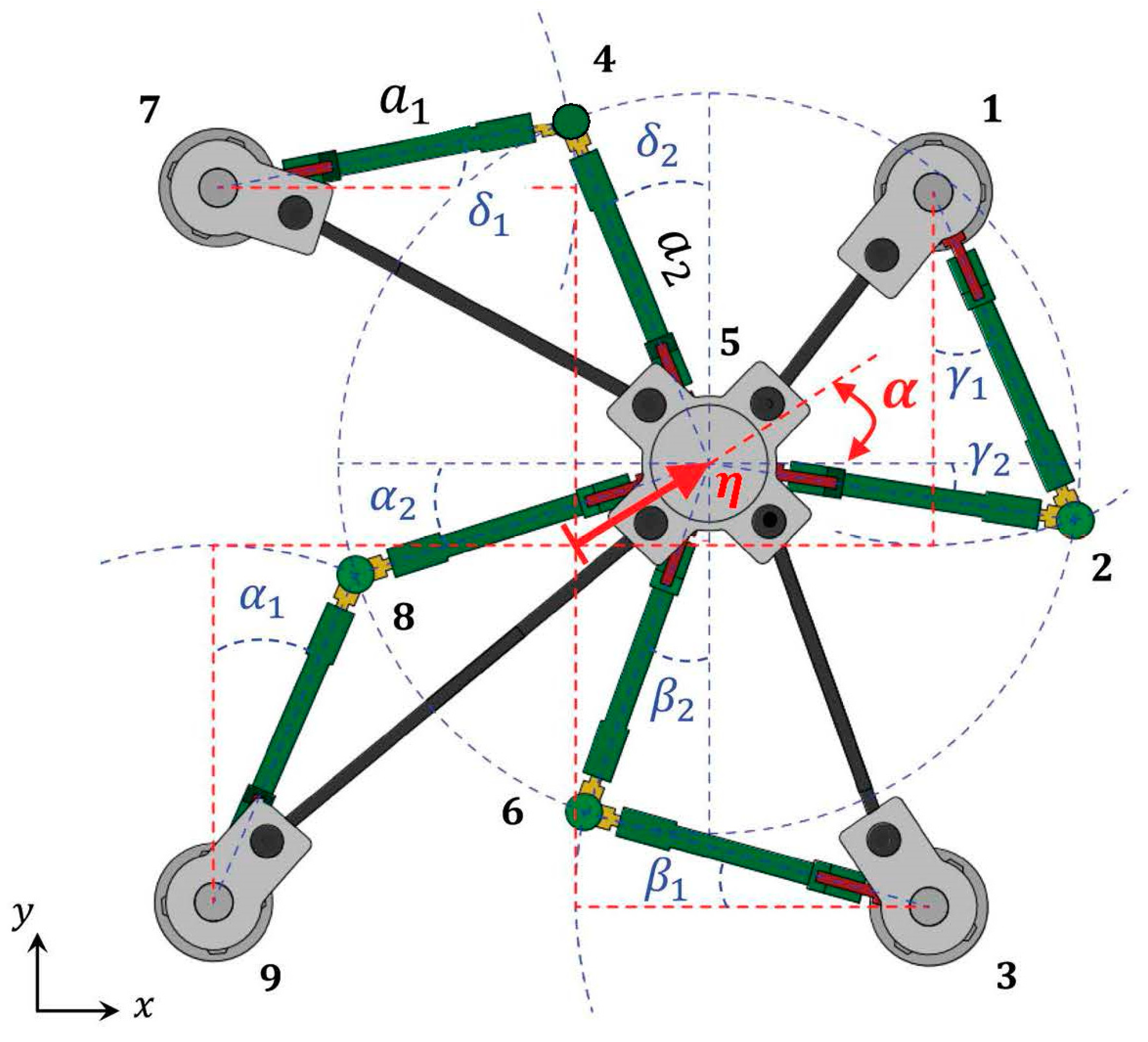
Let
and
denote the lengths of the two members forming each limb of the generic layer, and
;
;
;
the angles formed by such members with the axes of Cartesian fame
, as shown in
Figure 2. The deformed positions of the elbow/knee joints are obtained by intersecting a circle with a radius
centered at a corner post and a circle with a radius
centered at the deformed position of the central post. The latter is obtained by giving to such a post a displacement with magnitude
(
in the bottom layer;
in the top layer), along a direction inclined at an arbitrary angle
with the
-axis (
Figure 2).
Said (
the deformed positions of all the joints forming the current layer (
, see
Figure 2), the rotation angles of the limb members are obtained by solving the following compatibility equations:
The solution to Equation (1) can be obtained numerically [
23]. Once one of the rotation angles of the limb members
α1,
α2, …,
δ1,
δ2 has been computed from such equations, one obtains the deformed positions of all the free nodes of each layer, for any couple
) (
Figure 2).
We now pass on to derive the constitutive response
vs.
response of the SSI2, with
;
equal to either
or
;
equal to either
or
; and
equal to either
or
(
Figure 1B). By summing up the restoring forces carried out by all the tendons attached to the central post of the generic layer, we obtain
where the index
runs on all the tendons (
);
indicates the “pseudo-elastic” stress (
) vs. stretch ratio (
) model of the generic tendon (see
Section 4);
indicates a strain rate parameter; and it results in
(see [
23] and
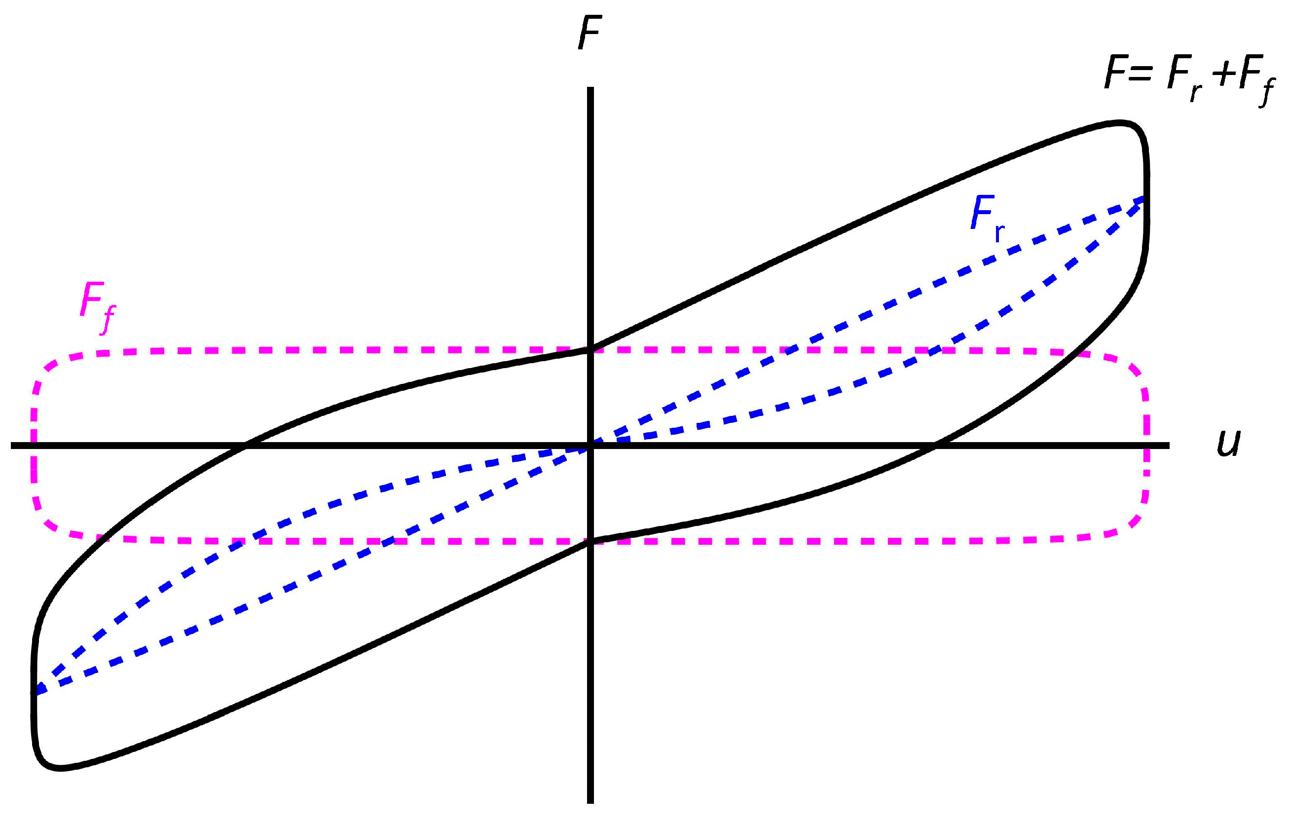
Section 4). The constitutive model of the friction force is as follows
where
is the vertical load;
is the sliding velocity (having employed the superimposed dot to denote time derivatives); and
is a friction coefficient that depends on the current values of
and
through
In Equation (4),
and
denote reference values of the vertical load and the sliding velocity, respectively, while
and
indicate additional constitutive parameters [
10]. The experimental results presented in [
23] and those given in
Section 4 of the present manuscript show that the adopted model (
Figure 3) adequately captures the recentering action of the tendons on the central post, and the friction effects acting at the interfaces between the sliders placed at the extremities of the central post and the terminal plates.
3. Experimental Tests on Physical Samples
Experimental tests were run on two physical models of the SSI2 by following the recommendations of the European Standard EN 15129 Anti-seismic devices [
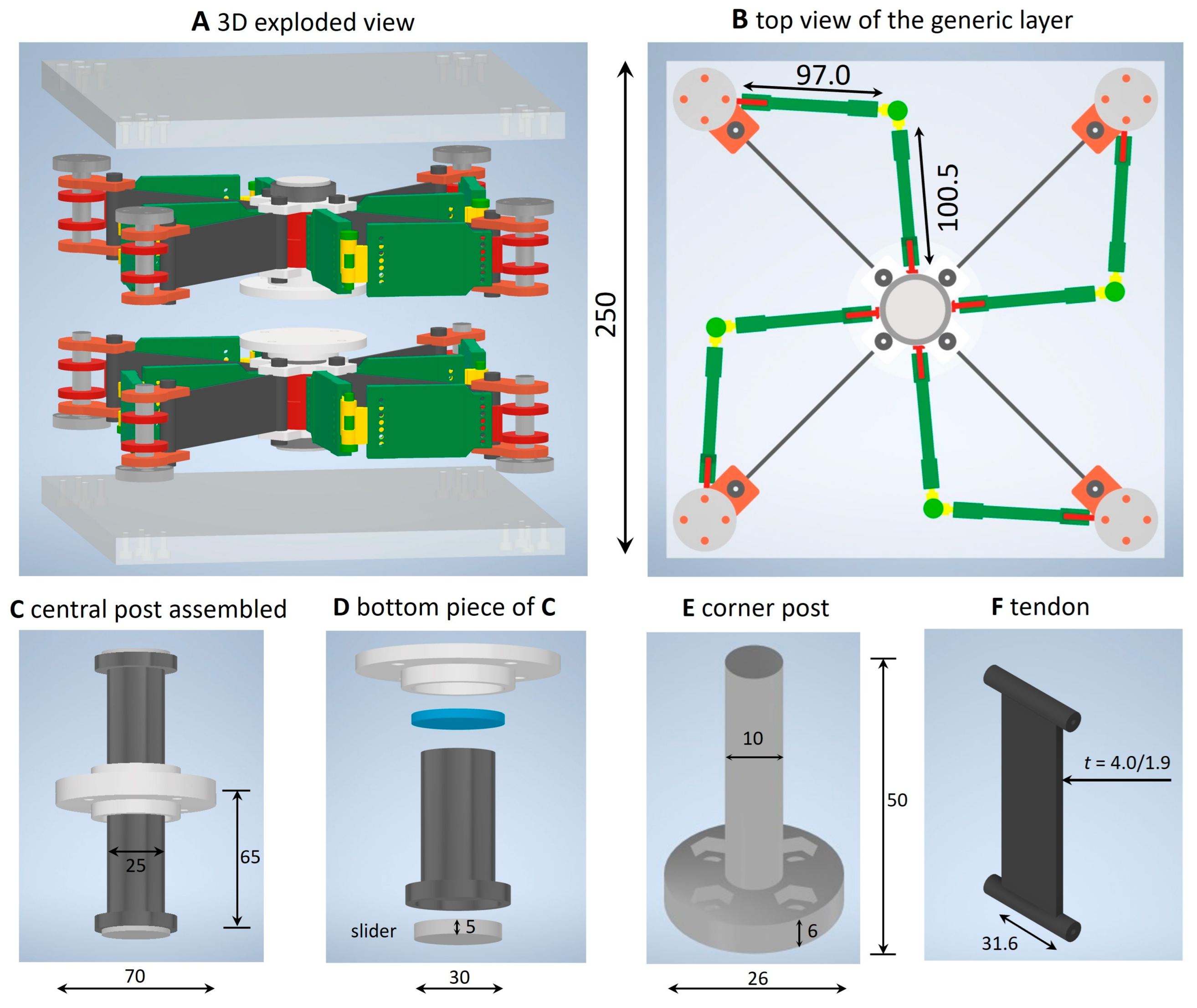
29], for what concerns both the general design rules and the testing requirements. The examined specimens are graphically illustrated in
Figure 4 and
Figure 5. They feature two identical superimposed layers exhibiting the following geometrical properties: limb lengths
= 97.0 mm,
= 100.5 mm (
Figure 2); central post made of S235 steel (235 MPa yield strength; 360 MPa ultimate strength; 210 GPa Young modulus, 7.85 g/cm
3 mass density [
30]) with a cylindrical core with a 25 mm diameter, fitted with a 70 mm diameter cap, for a total height (including the cap and the slider) of 65 mm; sliders consisting of circular discs with 30 mm diameters and 5 mm thickness made of polytetrafluoroethylene (PTFE: properties given in [
23,
31,
32]); S235 steel corner posts exhibiting a 10 mm diameter cylindrical core, a 26 mm diameter base enlargement with a 6 mm height, and a total height of 50 mm. The prototypes are confined between two square plates made of an Aluminum 7075-T651 alloy (Ergal) with a 250 mm edge and a 15 mm thickness (572 MPa yield strength; 503 MPa ultimate strength; 71.7 GPa Young modulus, 2.81 g/cm
3 mass density).
The tendons have a prismatic central region with a 31.6 mm height and thickness
variable from 4.0 mm (sample #1) down to 1.9 mm (sample #2). These elements are 3D printed, making use of a filament of thermoplastic polyurethane (TPU) for fused deposition modeling (FDM). They terminate with cylindrical rods that are inserted into rings attached to the corner posts and have encased steel bolts acting as stiffeners. The non-structural parts of the analyzed SSI2 prototypes (e.g., the limb members) are instead 3D printed using an eco-friendly polylactic acid (PLA) filament for FDM, with a mass density of 1.24 g/cm
3, tensile strength at yield of 50 MPa, and a tensile elastic modulus of 3.60 GPa. Each of the two layers forming these systems has the same geometry as the single layer used by the SSI1 studied in [
23], to which the reader is referred for further details about the geometry of the device and the rapid prototyping techniques used for its fabrication. The dimensions of the analyzed samples correspond to small-scale isolation devices of the kind used, e.g., for the seismic protection of artworks in museums [
6].
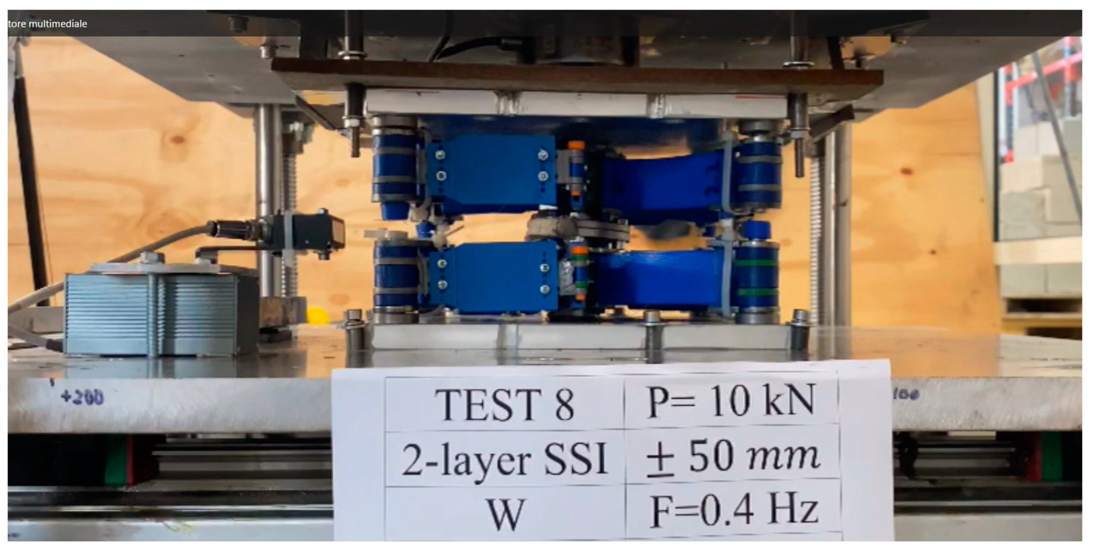
Experimental characterization of the analyzed SSI2 samples was carried out using a shake-table setup for the testing of small- and medium-scale prototypes of seismic isolators available at the Laboratory of Structural Engineering of the University of Salerno. The key properties of this setup, which is diffusely illustrated in Ref. [
33], are described in
Table 1. We applied two values of the vertical load, namely
and
, in association with sinusoidal displacement histories of each layer of the samples under testing, which show 0.4 Hz frequency,
mm amplitude, and are composed of a number of training cycles variable between 2 and 4 and 3 additional loading cycles. The overall displacement capacity (displacement drift) of the tested specimen is
mm. The load cells and the laser sensors illustrated in [
33] were used to measure vertical and horizontal forces and horizontal displacements, respectively.
The matrix of the examined tests is presented in
Table 2. It is worth noting that the couples of tests 5,7; 6,8; 9,11; and 10,12 provide repetitions of identical loading conditions. Viky Grease n. 51A by Viky
® (
https://viky.viky.it/, accessed on 4 September 2023) was employed as a lubricant in correspondence to the sliders of each layer. Additional tests were run to perform the preconditioning of the tendons [
23] and for calibration purposes.
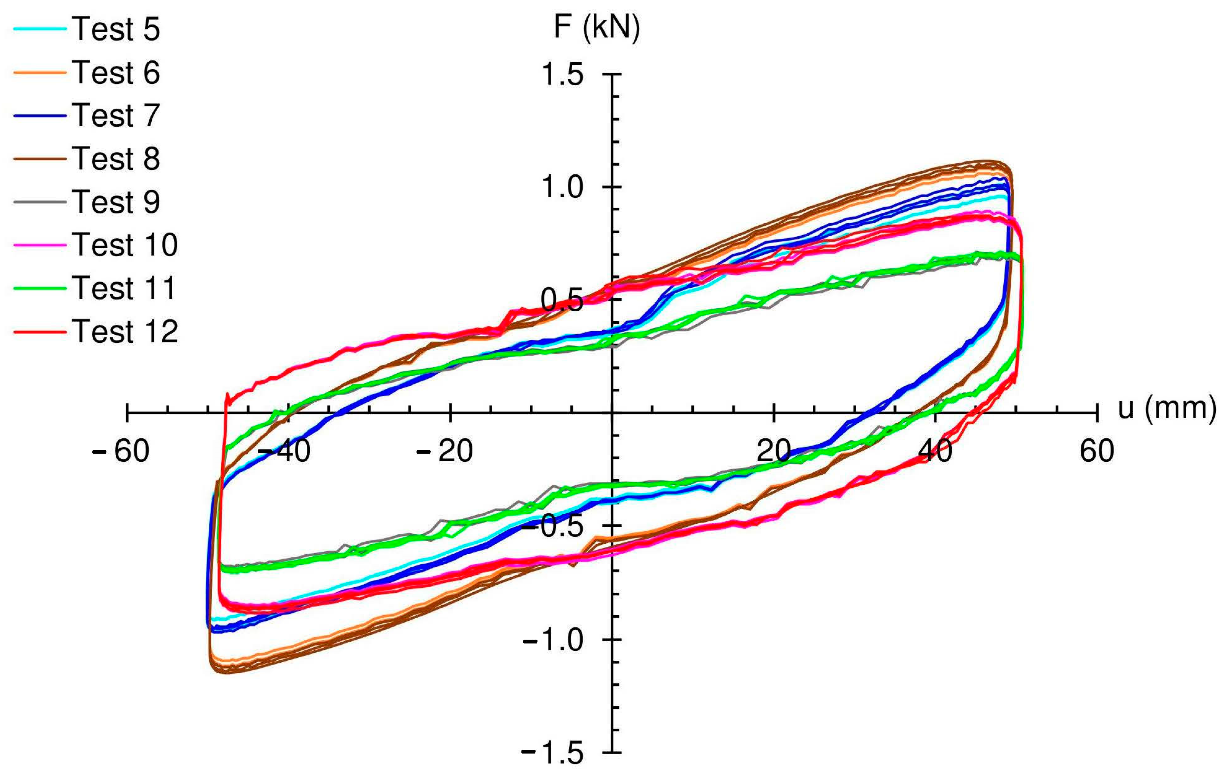
Figure 6 shows the
F vs.
u responses of the tested samples (after the training cycles), which highlight the achievement of the maximum (absolute) lateral force in correspondence to sample #1 with 4.0 mm thickness of the tendons–membranes under
P = 10 kN (test #8), and the minimum (absolute) lateral force in correspondence to sample #2 with 1.9 mm thickness of the tendons under
P = 5 kN (test #11). One also observes from the results in
Figure 6 that the samples equipped with 4.0 mm tendons exhibit more marked recentering components of the
F-u laws (tests #7,8), as compared to the samples exhibiting 1.9 mm tendons (tests #11,12). The
F-u curves recorded for tests #7,8 indeed exhibit loading and unloading branches with slightly larger slopes, over the
F-u curves recorded for tests #11,12. The latter instead shows a more pronounced oval profile, which indicates the prevalence of the friction component on the overall
F-u response (cf.
Figure 3). The effective properties of the examined samples are discussed in the following section. Illustrative movies of the examined tests are provided as
Supplementary Materials (Movies S1–S4). 4. Fitting of the Theoretical Model to the Experimental Results
We fitted the mechanical model of
Section 2 to the experimental results presented in the previous section. For what concerns the constitutive model of the tendons, we make use of the pseudo-elastic stress–strain law formulated in [
23] in the absence of permanent strains, assuming that the preconditioning of these members reduces such deformations nearly to zero [
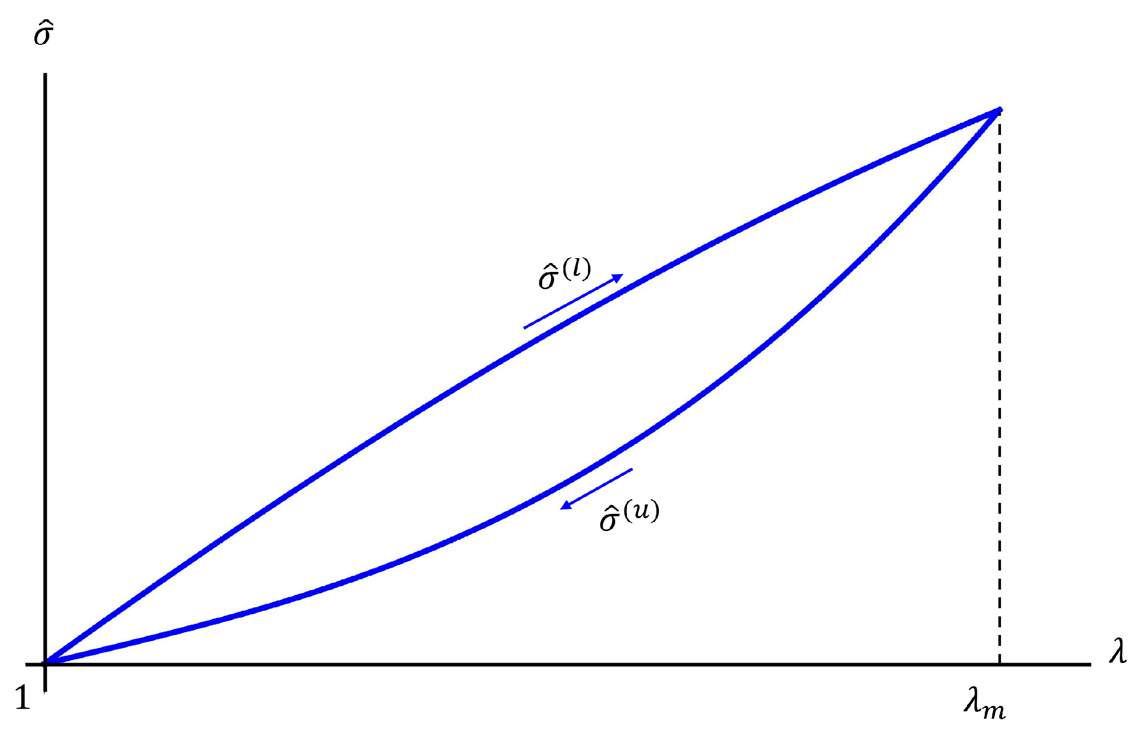
31]. We hereafter summarize the above model, which contemplates different shapes of the relationship between the nominal stress
and the stretch ratio
along the loading and unloading branches, as shown in
Figure 7. The loading branch is described by the equation
where
is the Yeoh hyperelastic strain energy function defined as
Using the results of experimental tests on 3D-printed TPU membranes presented in [
23], we assume
c1 = 4.19579 MPa,
c2 = 4.85976 MPa, and
c3 = 9.67521 MPa. The unloading branch is instead defined through the following softening model [
34]
where
and
are constitutive parameters and
denotes the value of the strain energy function
in correspondence to the maximum stretch ratio
reached during the loading phase (
Figure 7). Following [
23], we hereafter use
and
MPa.
The overall fitting of the mechanical model to the experimental results of the previous section is completed by introducing different assumptions for sample #1 and sample #2. Going into detail for sample #1, we assume the strain rate factor
along both the loading and unloading branches, and the friction law parameters
kN;
m/s;
1.688%; and
= 4.0. For sample #2, we instead assume
along the loading branch;
along the unloading branch (as in [
23]);
kN;
m/s;
1.899%; and
= 4.0. The reason for such different constitutive parameter choices is that we observed more pronounced rate-sensitivity effects in the force-displacement response of the sample with thinner tendons (sample #2,
mm), for both recentering and friction components, as compared to the response of the sample equipped with thicker tendons (sample #1,
mm).
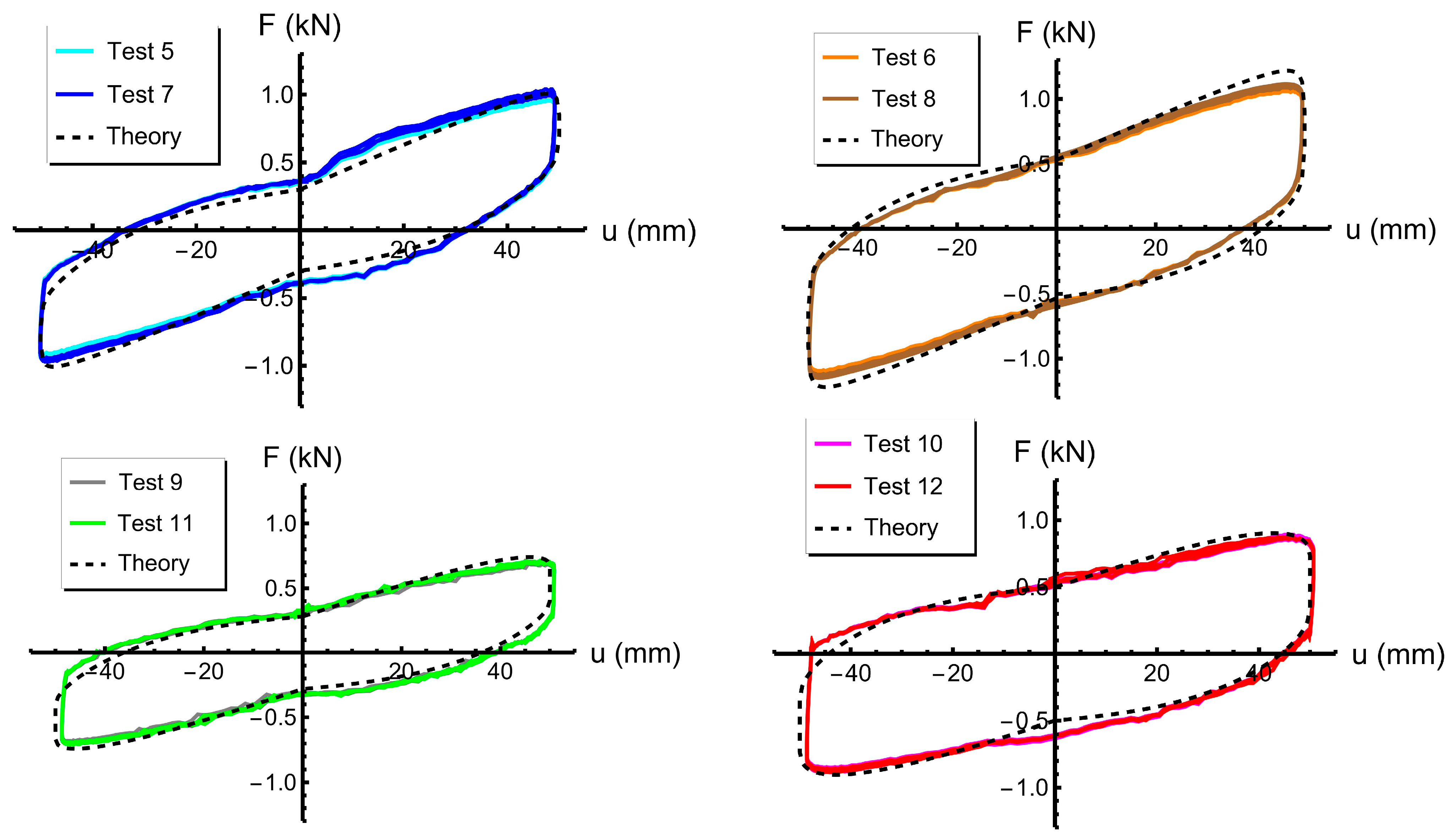
Figure 8 shows a comparison between the force–displacement responses predicted by the adopted mechanical models and the experimentally recorded responses. A rather good matching between theoretical predictions and experimental results is observed.
We now move on to compute the effective vibration period
and the effective damping coefficient
associated with the theoretical model, defined as follows [
23,
29]
Here,
is the energy dissipated per cycle;
(
denoting the gravitational acceleration);
is the displacement capacity (
mm in the examined tests); and
is the lateral force exhibited by the device for
.
Table 3 shows the values of the effective dynamic parameters
and
, estimated for the examined tests. One observes that the values of both
and
grow with increasing values of the vertical load, for a given value of the thickness of the tendons, and also by increasing the thickness of the members, for a given value of the vertical load. Considerably large values of the effective
(that are appreciably greater than 30%) were recorded in all the examined tests.
5. Concluding Remarks
We have experimentally and theoretically studied a two-layer version of a bioinspired seismic metaisolator that is able to protect multistory buildings from earthquakes by replicating the mechanics of the human body and animal locomotion through the combination of sliding–stretching mechanisms (SSI2 system). This study has achieved the following key innovative results, as compared to the pioneering study on single-layer, sliding–stretching isolators presented in [
23] (SSI1 systems): (i) the generalization of the mechanical model presented in [
23] to account for the presence of two superimposed layers that move along opposite directions; (ii) the possibility to double the displacement capacity of the system, with respect to a single-layer system with the same footprint; (iii) the experimental validation of the proposed mechanical model of the SSI2 against shake-table tests on scaled prototypes; and (iv) the variation of the mechanical response of the device with the size of the tendons. Due to its peculiar mechanics, the SSI2 is a good candidate for the seismic isolation of multistoried buildings, as well as for all the applications that require a considerably large displacement capacity in combination with a reduced footprint.
The analyzed metaisolator can be assembled from environmentally sustainable components, without heavy industry, being partially or fully achievable with ordinary 3D printers and biobased and/or recycled materials. The metallic parts can be manufactured using standard lathe machines, purchased from online metal parts suppliers, and/or fabricated with a desktop metal 3D printer. We have shown that the effective mechanical properties of the examined device can be suitably tuned by varying the size of the tendons, which makes the system easily adjustable to the structure being protected. It is also possible to distribute the vertical load among multiple posts, by tessellating the SSI2 unit cells in the horizontal plane [
23]. Future work will be devoted to the experimental analysis of a large variety of SSI systems and load conditions, as well as to the optimal design of the geometry, topology, and stacking sequence of the layers of the device, by employing soft-computing [
35], probabilistic methods [
36], and/or artificial intelligence techniques [
37].


 ,
, 


