
Experimental and Numerical Investigations of Laced Built-Up Lightweight Concrete Encased Columns Subjected to Cyclic Axial Load

 , , , , ,
  ,
,  ,
,  and
and
Abstract
1. Introduction
2. Materials and Methods
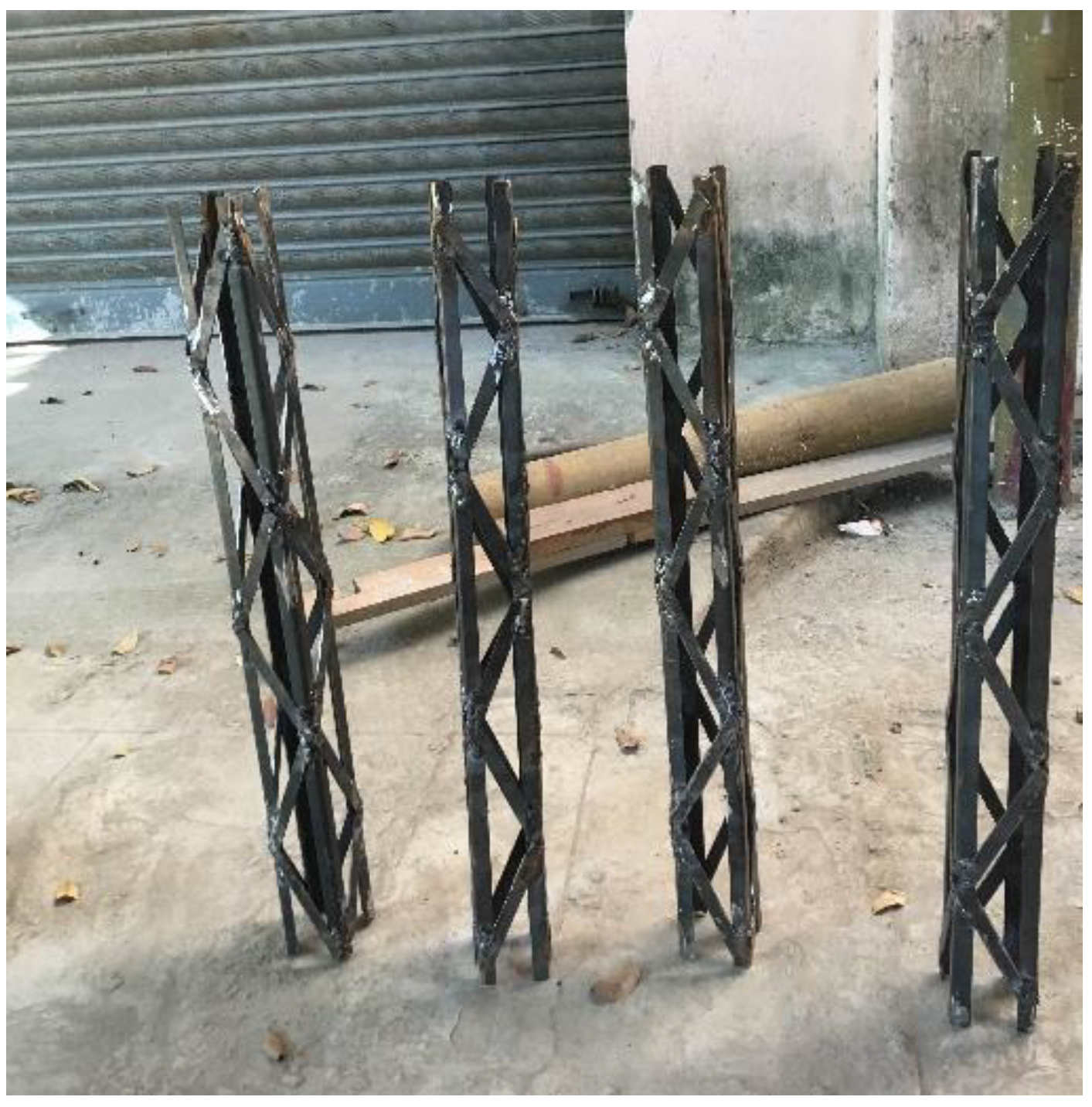
2.1. Proposed System
2.2. Experimental Investigation
2.3. Experimental Set-Up
2.4. Finite Element Analysis
- Element type selection
- Material properties assigning
- Geometry modeling and meshing
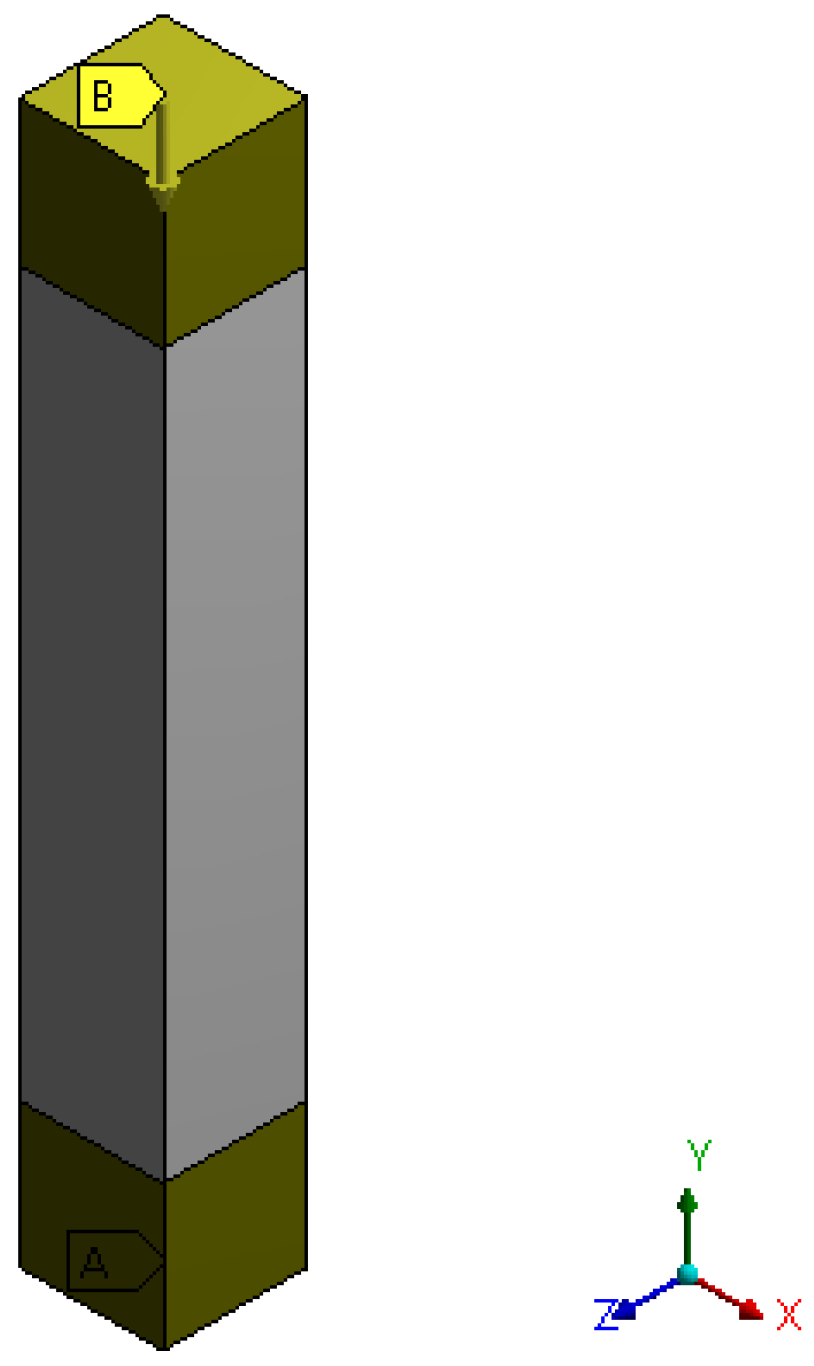
2.4.1. ANSYS Geometric Model
2.4.2. Finite Element Meshing
2.4.3. Application of Loads and Boundary Condition
3. Results and Discussion
3.1. Axial Shortening
3.2. Cracking Displacement
3.3. Ultimate Displacement
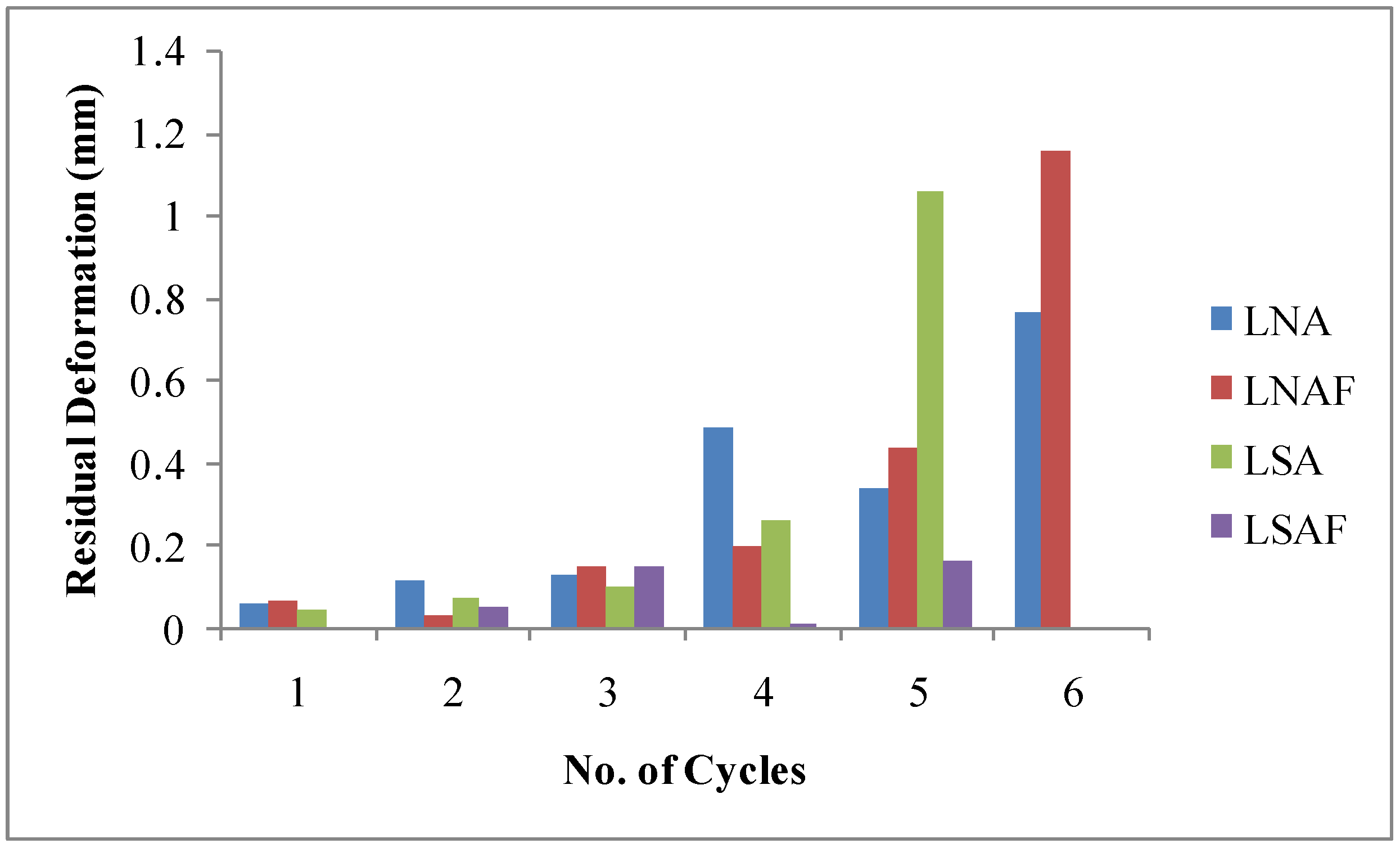
3.4. Residual Deformation
3.5. Energy Absorption Capacity
3.6. Ductility
3.7. Stiffness Degradation
3.8. Observed Behaviour and Failure Mode
3.9. Convergence of Experimental and Finite Element Modeling
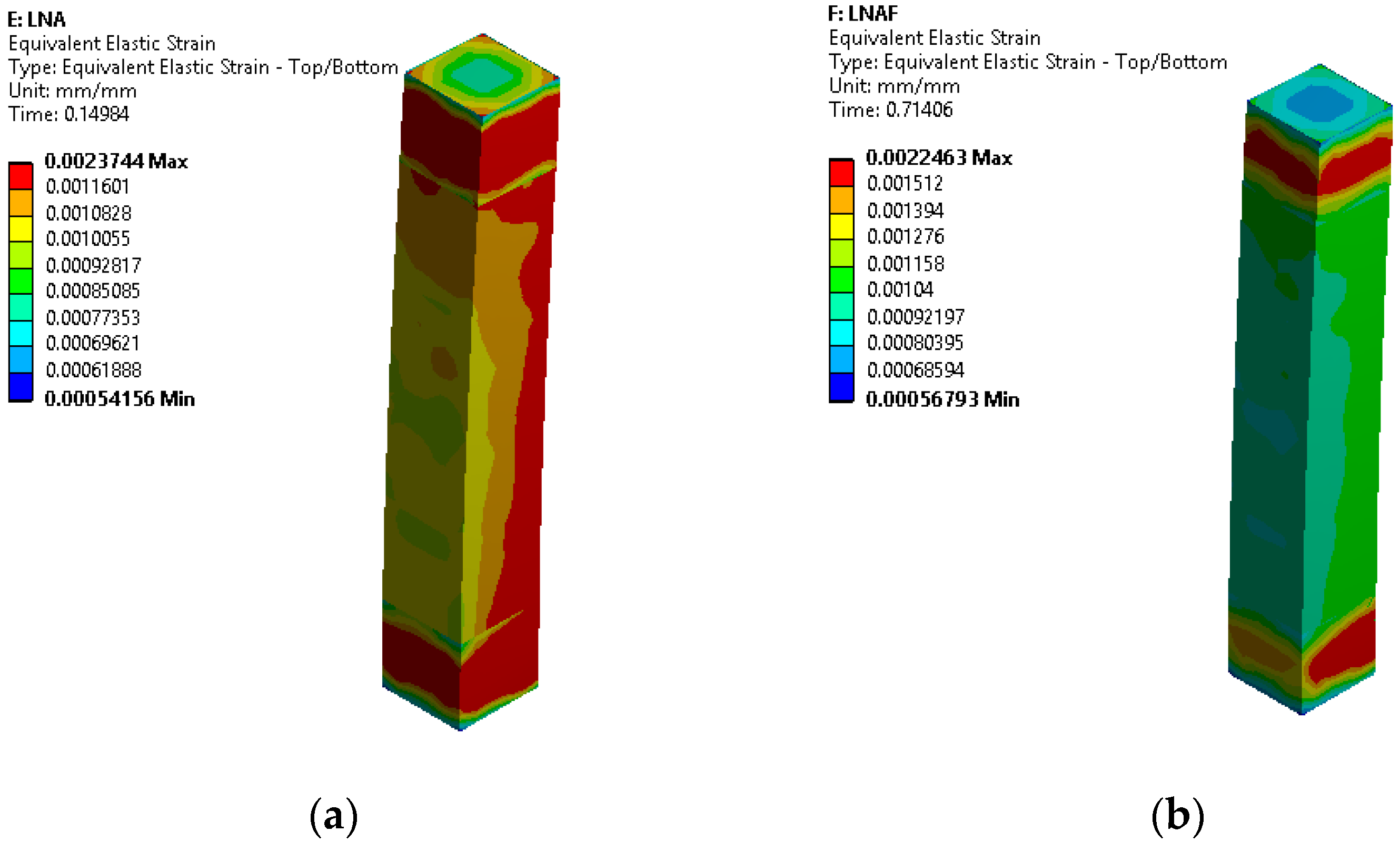
3.9.1. Strain Behavior
3.9.2. Deformation
4. Conclusions
- The axial deformation of columns LNA and LSA at failure was found to be 3.5 mm, whereas columns LNAF and LSAF reached an axial shortening of 4.5 mm at failure.
- There was no significant lateral deformation noted until the first three cycles. At the failure load, the lateral deformations of columns reinforced with basalt fiber were found to be significantly lower due to the fiber bridging phenomenon within the concrete matrix.
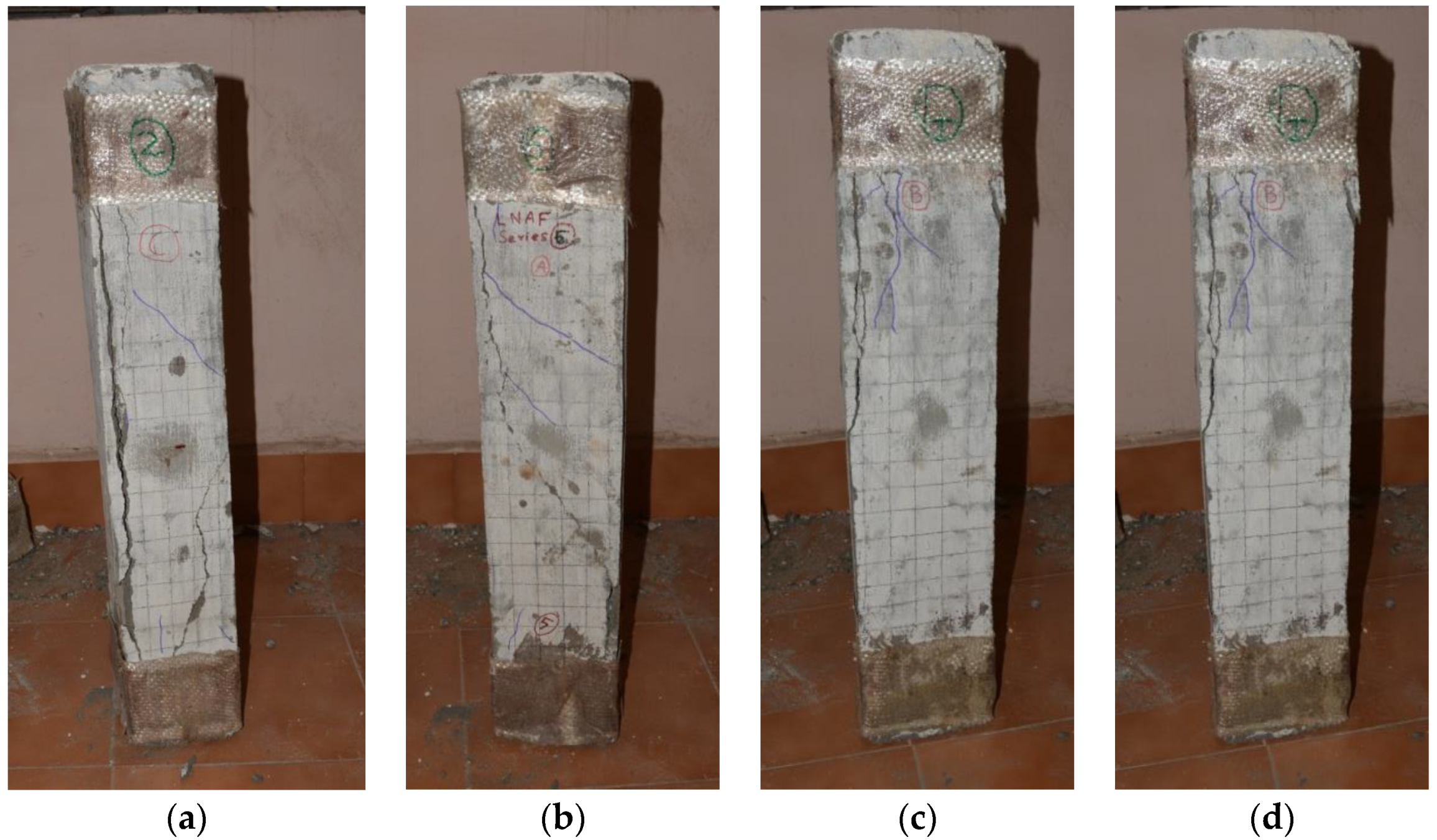
- The columns LNA and LSAF were pronounced with a major crack at the initiation loading phase of the 4th cycle, whereas the column LNAF was detected with a major crack at the commencement of the 5th cycle. The column LSA was found with a major crack at the 3rd cycle itself.
- The ultimate deformation of the column LNA was found to be greater when compared to other columns under all load cycles.
- At the end of load cycles, the columns LSA and LSAF are pronounced with more residual deformations.
- Column LSAF was found to have 5.3% more energy absorption than LSA and 11.5% less than column LNAF.
- Although the column LNAF was found to have a shear crack along the length of the specimen, it was found to be more ductile with more energy absorption than other columns.
- On tracing a failure envelope over the load-deformation curve, the columns were found to be well confined with better load-deformation characteristics.
- The ability of the columns to withstand large deformations without significant deformations is well pronounced by the column LNAF.
- When compared to the experimental results, the predictions based on finite elements demonstrated that the failure had occurred precisely where plastic hinges had been formed.
- The advantage of lightweight concrete combined with a better laced built-up section creates a unique composite system that performs well in vibration loading as normal-weight concrete.
- It is recommended to optimize the spacing between the steel angles so that there will be changes in the confinement effects and structural behavior. Also, the volume of basalt fibers can be increased for better performance in LSAF columns compared to LNAF columns.
Author Contributions
Funding
Institutional Review Board Statement
Informed Consent Statement
Data Availability Statement
Acknowledgments
Conflicts of Interest
References
- Ding, W.; Jia, S. An Improved Equation for the Bearing Capacity of Concrete-Filled Steel Tube Concrete Short Columns Based on GPR. Buildings 2023, 13, 1226. [Google Scholar] [CrossRef]
- Emperger, F.V. Welche Statische Bedeutung Hat Die Einbetonierungeiner Eisensaule; Beton Eisen: Berlin, Germay, 1907; pp. 172–174. [Google Scholar]
- Burr, W.H. The reinforced concrete work of the McGraw Building. Trans. Am. Soc. Civ. Eng. 1908, 60, 443–457. [Google Scholar] [CrossRef]
- Yee, K.M.; Shakir-Khalil, H.; Taylor, R. Design expressions for a new type of composite column. J. Constr. Steel Res. 1982, 2, 26–32. [Google Scholar] [CrossRef]
- Weng, C.C.; Yen, S.I. Comparisons of concrete-encased composite column strength provisions of ACI Code and AISC specification. Eng. Struct. 2002, 24, 59–72. [Google Scholar] [CrossRef]
- Eom, T.-S.; Yang, J.-M.; Kim, D.-K.; Lim, J.-J.; Lee, S.-H. Experimental investigation of bolted end-plate angle splice in encased composite columns. Eng. Struct. 2019, 190, 31–40. [Google Scholar] [CrossRef]
- Lai, B.; Liew, J.Y.R.; Hoang, A.L. Behavior of high strength concrete encased steel composite stub columns with C130 concrete and S690 Steel. Eng. Struct. 2019, 200, 109743. [Google Scholar] [CrossRef]
- Khan, M.K.I.; Rana, M.M.; Zhang, Y.X.; Lee, C.K. Compressive behaviour of engineered cementitious composites and concrete encased steel composite columns. J. Constr. Steel Res. 2020, 167, 105967. [Google Scholar] [CrossRef]
- AISC Frames and Other Structures. Specification for Structural Steel Buildings (Allowable Stress Design and Plastic Design); American Institute of Steel Construction: Chicago, IL, USA, 1989; pp. 136–138. [Google Scholar]
- ANSI/AISC 360-16; AISC Specification for Structural Steel Buildings. American Institute of Steel Construction: Chicago, IL, USA, 2010; p. 676.
- Soman, M.; Mohan, J. Rehabilitation of RC columns using Ferrocement jacketing. Constr. Build. Mater. 2018, 181, 156–162. [Google Scholar] [CrossRef]
- Campian, C.; Nagy, Z.; Pop, M. Behavior of fully encased steel-concrete composite columns subjected to monotonic and cyclic loading. Procedia Eng. 2015, 117, 439–451. [Google Scholar] [CrossRef]
- Raju, S.; Rathinam, J.; Dharmar, B.; Rekha, S.; Avudaiappan, S.; Amran, M.; Usanova, K.I.; Fediuk, R.; Guindos, P.; Ramamoorthy, R.V. Cyclically Loaded Copper Slag Admixed Reinforced Concrete Beams with Cement Partially Replaced with Fly Ash. Materials 2022, 15, 3101. [Google Scholar] [CrossRef]
- Giménez, E.; Adam, J.M.; Ivorra, S.; Calderón, P.A. Influence of strips configuration on the behaviour of axially loaded RC columns strengthened by steel angles and strips. Mater. Des. 2009, 30, 4103–4111. [Google Scholar] [CrossRef]
- Hosseini Hashemi, B.; Jafari, M.A. Experimental Evaluation of Elastic Critical Load in Batten columns. J. Constr. Steel Res. 2009, 65, 125–131. [Google Scholar] [CrossRef]
- Lee, K.; Bruneau, M. Seismic vulnerability evaluation of axially loaded steel built-uplaced members I: Experimental results. Earthq. Eng. Eng. Vib. 2008, 7, 113–124. [Google Scholar] [CrossRef]
- Dar, M.A.; Sahoo, D.R.; Pulikkal, S.; Jain, A.K. Behaviour of laced built-up cold-formed steel columns: Experimental Investigation and Numerical Validation. Thin-Walled Struct. 2018, 132, 398–409. [Google Scholar] [CrossRef]
- Wasserman, R.; Bentur, A. Interfacial interactions in lightweight aggregate concretes and their influence on the concrete strength. Cem. Concr. Compos. 1996, 18, 67–76. [Google Scholar] [CrossRef]
- Wasserman, R.; Bentur, A. Effect of lightweight fly ash aggregate microstructure on the strength of concretes. Cem. Concr. Res. 1997, 27, 525–537. [Google Scholar] [CrossRef]
- Jayanthi, V.; Avudaiappan, S.; Amran, M.; Arunachalam, K.P.; Qader, D.N.; Delgado, M.C.; Flores, E.I.S.; Rashid, R.S. Innovative use of micronized biomass silica-GGBS as agro-industrial by-products for the production of a sustainable high-strength geopolymer concrete. Case Stud. Constr. Mater. 2022, 18, e01782. [Google Scholar] [CrossRef]
- Semenov, P.A.; Uzunian, A.V.; Davidenko, A.M.; Derevschikov, A.A.; Goncharenko, Y.M.; Kachanov, V.A.; Khodyrev, V.Y.; Meschanin, A.P.; Minaev, N.G.; Mochalov, V.V.; et al. First Study of radiation hardness of lead tungstate crystals at low temperatures. Nucl. Instrum. Methods Phys. Res. Sect. A Accel. Spectrometers Detect. Assoc. Equip. 2007, 582, 575–580. [Google Scholar] [CrossRef]
- Tangtermsirikul, S.; Wijeyewickrema, A.C. Strength evaluation of aggregate made from fly ash. ScienceAsia 2000, 26, 237. [Google Scholar] [CrossRef]
- Sheeba, K.R.J.; Priya, R.K.; Arunachalam, K.P.; Avudaiappan, S.; Maureira-Carsalade, N.; Roco-Videla, Á. Characterisation of Sodium Acetate Treatment on Acacia pennata Natural Fibres. Polymers 2023, 15, 1996. [Google Scholar] [CrossRef]
- Haque, M.N.; Al-Khaiat, H.; Kayali, O. Strength and durability of lightweight concrete. Cem. Concr. Compos. 2004, 26, 307–314. [Google Scholar] [CrossRef]
- Rohman, R.K.; Aji, S. Effect of fly ash on compressive strength of concrete containing recycled coarse aggregate. AIP Conf. Proc. 2018, 2014, 020097. [Google Scholar] [CrossRef]
- Güneyisi, E.; Gesoğlu, M.; Pürsünlü, Ö.; Mermerdaş, K. Durability aspect of concretes composed of cold bonded and sintered fly ash lightweight aggregates. Compos. Part B Eng. 2013, 53, 258–266. [Google Scholar] [CrossRef]
- Kayali, O. Fly ash lightweight aggregates in high performance concrete. Constr. Build. Mater. 2008, 22, 2393–2399. [Google Scholar] [CrossRef]
- Kockal, N.U.; Ozturan, T. Effects of lightweight fly ash aggregate properties on the behavior of lightweight concretes. J. Hazard. Mater. 2010, 179, 954–965. [Google Scholar] [CrossRef]
- Gomathi, P.; Sivakumar, A. Accelerated curing effects on the mechanical performance of cold bonded and sintered fly ash aggregate concrete. Constr. Build. Mater. 2015, 77, 276–287. [Google Scholar] [CrossRef]
- Arunachalam, K.P.; Avudaiappan, S.; Flores, E.I.S.; Parra, P.F. Experimental Study on the Mechanical Properties and Microstructures of Cenosphere Concrete. Materials 2023, 16, 3518. [Google Scholar] [CrossRef] [PubMed]
- Divyah, N.; Thenmozhi, R.; Neelamegam, M. Experimental and numerical analysis of battened built-up lightweight concrete encased composite columns subjected to axial cyclic loading. Lat. Am. J. Solids Struct. 2020, 17, e259. [Google Scholar] [CrossRef]
- Jiang, C.; Fan, K.; Wu, F.; Chen, D. Experimental study on the mechanical properties and microstructure of chopped basalt fibre reinforced concrete. Mater. Des. 2014, 58, 187–193. [Google Scholar] [CrossRef]
- Qin, J.; Qian, J.; Li, Z.; You, C.; Dai, X.; Yue, Y.; Fan, Y. Mechanical properties of basalt fiber reinforced magnesium phosphate cement composites. Constr. Build. Mater. 2018, 188, 946–955. [Google Scholar] [CrossRef]
- Kharun, M.; Koroteev, D.D.; Dkhar, P.; Zdero, S.; Elroba, S.M. Physical and mechanical properties of basalt-fibered high-strength concrete. Struct. Mech. Eng. Constr. Build. 2018, 14, 396–403. [Google Scholar] [CrossRef]
- Galishnikova, V.V.; Chiadighikaobi, P.C.; Emiri, D.A. Comprehensive view on the ductility of basalt fiber reinforced concrete focus on lightweight expanded clay. Struct. Mech. Eng. Constr. Build. 2019, 15, 360–366. [Google Scholar] [CrossRef]
- Han, L.; Ren, Q.; Li, W. Inclined, tapered and STS concrete-filled steel tubular (CFST) stub columns under axial compression. In Tubular Structures XIII, Proceedings of the 13th International Symposium on Tubular Structures, Hong Kong, China, 15–17 December 2010; CRC Press: Boca Raton, FL, USA, 2010; pp. 623–628. [Google Scholar] [CrossRef]
- Zhang, Y.; Liu, Y.; Xin, H.; He, J. Numerical parametric study on ultimate load and ductility of concrete encased equal-leg angle steel composite columns. Eng. Struct. 2019, 200, 109679. [Google Scholar] [CrossRef]
- Baláž, I.J.; Koleková, Y.P.; Moroczová, L.O. Behaviour of steel laced built-up columns. In Advances and Trends in Engineering Sciences and Technologies III; CRC Press: Boca Raton, FL, USA, 2019; pp. 29–35. [Google Scholar] [CrossRef]
- IS 801-1975; Practice for Use of Cold-Formed Light Gauge Steel Structural Members in General Building Construction. Bureau of Indian Standards: New Delhi, India, 1975.
- Hosseini Hashemi, B.; Poursamad Bonab, A. Experimental investigation of the behavior of laced columns under constant axial load and cyclic lateral load. Eng. Struct. 2013, 57, 536–543. [Google Scholar] [CrossRef]
- Tolstoy, A.; Lesovik, V.; Fediuk, R.; Amran, M.; Gunasekaran, M.; Vatin, N.; Vasilev, Y. Production of greener high-strength concrete using Russian quartz sandstone mine waste aggregates. Materials 2020, 13, 5575. [Google Scholar] [CrossRef] [PubMed]
- Kim, C.-S.; Park, H.-G.; Chung, K.-S.; Choi, I.-R. Eccentric axial load testing for concrete-encased steel columns using 800 MPA Steel and 100 MPA concrete. J. Struct. Eng. 2012, 138, 1019–1031. [Google Scholar] [CrossRef]
- Mazars, J.; Hamon, F.; Grange, S. A new 3D damage model for concrete under monotonic, cyclic and dynamic loadings. Mater. Struct. 2015, 48, 3779–3793. [Google Scholar] [CrossRef]
- Di Re, P.; Addessi, D.; Filippou, F. Mixed 3D Beam Element with Damage Plasticity for the Analysis of RC Members under Warping Torsion. J. Struct. Eng. 2018, 144, 04018064. [Google Scholar] [CrossRef]
- Yuan, F.; Wu, Y.-F. Effect of load cycling on plastic hinge length in RC Columns. Eng. Struct. 2017, 147, 90–102. [Google Scholar] [CrossRef]
- Paul, M. Buckling loads for built-up columns with stay plates. J. Eng. Mech. 1995, 121, 1200–1208. [Google Scholar] [CrossRef]


| Sl No. | Column ID | Type of Concrete | fck (MPa) | E (GPa) | Density (kg/m3) |
|---|---|---|---|---|---|
| 1 | LNA | Normal weight concrete | 38.04 | 305 | 2567 |
| 2 | LNAF | Fiber-reinforced normal-weight aggregate concrete | 40.56 | 353 | 2671 |
| 3 | LSA | Lightweight concrete | 38.62 | 223 | 2113 |
| 4 | LSAF | Fiber-reinforced lightweight aggregate concrete | 41.88 | 299 | 2220 |
| S. No | Name | Material | ANSYS Element |
|---|---|---|---|
| 1. | Concrete | NA, NAF, SA, SAF | Solid 185 |
| 2. | Steel Angle section (12 × 12 × 1.6 mm) | CFS | BEAM 188 |
| 3. | End Wrapping | GFRP | Shell 181 |
| Column ID | First Crack | Ultimate | ||
|---|---|---|---|---|
| Load (kN) | Deformation (mm) | Load (kN) | Deformation (mm) | |
| LNA | 295 | 0.993 | 386.0035 | 1.559 |
| LNAF | 306 | 0.84 | 417.238 | 1.507 |
| LSA | 298 | 1.11 | 387.562 | 2.068 |
| LSAF | 303 | 0.998 | 421.345 | 1.864 |
| Column ID | Experiment | ANSYS | ||||
|---|---|---|---|---|---|---|
| Load (kN) | Axial Deformation (mm) | Lateral Deformation (mm) | Load (kN) | Axial Deformation (mm) | Lateral Deformation (mm) | |
| LNA | 386.00 | 1.559 | 0.302 | 400.56 | 1.569 | 0.32 |
| LNAF | 417.24 | 1.507 | 0.527 | 425.64 | 1.567 | 0.566 |
| LSA | 387.56 | 2.068 | 1.46 | 397.16 | 2.081 | 1.559 |
| LSAF | 421.34 | 1.864 | 0.303 | 434.31 | 1.91 | 0.308 |
Disclaimer/Publisher’s Note: The statements, opinions and data contained in all publications are solely those of the individual author(s) and contributor(s) and not of MDPI and/or the editor(s). MDPI and/or the editor(s) disclaim responsibility for any injury to people or property resulting from any ideas, methods, instructions or products referred to in the content. |
© 2023 by the authors. Licensee MDPI, Basel, Switzerland. This article is an open access article distributed under the terms and conditions of the Creative Commons Attribution (CC BY) license (https://creativecommons.org/licenses/by/4.0/).
Share and Cite
Divyah, N.; Prakash, R.; Srividhya, S.; Avudaiappan, S.; Guindos, P.; Carsalade, N.M.; Arunachalam, K.P.; Noroozinejad Farsangi, E.; Roco-Videla, Á. Experimental and Numerical Investigations of Laced Built-Up Lightweight Concrete Encased Columns Subjected to Cyclic Axial Load. Buildings 2023, 13, 1444. https://doi.org/10.3390/buildings13061444
Divyah N, Prakash R, Srividhya S, Avudaiappan S, Guindos P, Carsalade NM, Arunachalam KP, Noroozinejad Farsangi E, Roco-Videla Á. Experimental and Numerical Investigations of Laced Built-Up Lightweight Concrete Encased Columns Subjected to Cyclic Axial Load. Buildings. 2023; 13(6):1444. https://doi.org/10.3390/buildings13061444
Chicago/Turabian StyleDivyah, Nagarajan, Ramaiah Prakash, Sundaresan Srividhya, Siva Avudaiappan, Pablo Guindos, Nelson Maureira Carsalade, Krishna Prakash Arunachalam, Ehsan Noroozinejad Farsangi, and Ángel Roco-Videla. 2023. "Experimental and Numerical Investigations of Laced Built-Up Lightweight Concrete Encased Columns Subjected to Cyclic Axial Load" Buildings 13, no. 6: 1444. https://doi.org/10.3390/buildings13061444
APA StyleDivyah, N., Prakash, R., Srividhya, S., Avudaiappan, S., Guindos, P., Carsalade, N. M., Arunachalam, K. P., Noroozinejad Farsangi, E., & Roco-Videla, Á. (2023). Experimental and Numerical Investigations of Laced Built-Up Lightweight Concrete Encased Columns Subjected to Cyclic Axial Load. Buildings, 13(6), 1444. https://doi.org/10.3390/buildings13061444