Abstract
Suspension bridges’ in-plane extended configuration makes them vulnerable to wind-induced vibrations. Vortex shedding is a kind of aerodynamic phenomenon causing a bridge to vibrate in vertical and torsional modes. Vortex-induced vibrations disturb the bridge’s serviceability limit, which is not favorable, and in the long run, they can cause fatigue damage. In this condition, vibration control strategies seem to be essential. In this paper, the performance of a tuned mass damper (TMD) is investigated under the torsional vortex phenomenon for an ultra-span streamlined twin-box girder suspension bridge. In this regard, the sensitivity of TMD parameters was addressed according to the torsional responses of the suspension bridge, and the reached appropriate ranges are compared with the outputs provided by genetic algorithm. The results indicated that the installation of three TMDs could control all the vulnerable modes and reduce the torsional rotation by up to 34%.
1. Introduction
Within the variety of bridge designs, suspension bridges are known for their capacity to span vast distances, often being the top choice for connecting distant points through extended structural spans. Consequently, the significance of wind-driven oscillations for these bridges increases as their span lengthens. These bridges can vibrate independently in four primary modes—vertical, longitudinal, lateral, and torsional—or as a blend of these modes [1,2,3]. Aerodynamic phenomena, such as vortex-shedding, galloping, buffeting, static divergence, and flutter, are caused by the interaction between airflow and a broad structure like a bridge deck. Vortex shedding is the primary cause of structural vibrations in the direction perpendicular to the airflow, although other velocity-dependent forces become relevant when the induced motion is substantial [4].
Recently, vortex-induced vibration (VIV) has been detected on numerous bridges globally, including Japan’s Trans-Tokyo Bay Bridge [5], Russia’s Volgograd Bridge [6], China’s Xihoumen Bridge, Yingwuzhou Yangtze River Bridge, and Humen Bridge [7], as well as Denmark’s Great Belt Bridge. It is essential to acknowledge that vortex shedding-induced oscillations are predominantly resonant, self-regulating, narrowly focused, and usually occur at low wind speeds, impacting driving safety, contributing to long-term fatigue damage, and reducing the average bridge life span [8,9,10].
If it is determined that a structure does not meet aerodynamic requirements, there are three strategies for bridge control under VIV as follows [11,12,13]:
- Prevent vortex shedding by refining the bridge deck’s aerodynamic design, utilizing distinct streamlined box girders.
- Modify the bridge’s dynamic properties by changing its structural layout.
- Enhance stability by incorporating additional attachments such as spoilers, guide vanes, or flapping plates.
The tuned mass damper (TMD) system, a passive mechanical control approach, falls under the third strategy and is frequently employed in suspension bridges to manage vibrations resulting from various load types. Three primary parameters make up a TMD, specifically, mass ratio, tuning frequency, and damping ratio [14,15]. Originally conceived by Frahm [16], the TMD was a spring-mass system that could only dampen vibrations of a single frequency because of its inability to retain excess energy. Den Hartog [17] later proposed a set of optimal TMD design formulas based on fixed-point theory and included a viscous damper into the system, making it the most commonly used setup.
A novel passive system was tested in a wind tunnel and shown to be effective by Kwon et al. [18], who used a TMD mechanism to activate a plate and adjust the airflow on the deck. Gu et al. [19] proposed a new lever-type TMD to counteract wind-induced vibrations, testing their suggested control system on the Yichang suspension bridge and demonstrating greater efficiency than a passive TMD. Pourzeynali and Datta [20] examined the effects of TMD parameters on accelerating the rate of flutter, finding that TMD did not introduce any instability. Chen and Kareem [21] studied TMD’s effectiveness in controlling a bridge’s flutter, including an optimal TMD design strategy based on the negative damping of systems.
A unique control strategy for dampening modal coupling effects and reducing resonant vibrations via TMDs was proposed by Chen and Cai [22]. The effectiveness of TMD in increasing the gallop speed of flexible suspension bridges without modifying their forms was studied by Abdel-Rohman and John [23]. Domaneschi et al. [24] studied how TMD can be used to manage buffeting on suspension bridges. For the Vincent Thomas suspension bridge, Alizadeh et al. [25] conducted a sensitivity analysis of flutter velocity concerning the gyration radius and placement of TMDs. Kontoni and Farghaly [26] used tuned mass dampers to mitigate soil-structure interaction effects on a cable-stayed bridge’s seismic response. Finally, Mansouri et al. [27] investigated how far-fault earthquake duration, severity, and size affected the seismic response of RC bridges retrofitted with seismic bearings.
Patil and Jangid [28] and Bandivadekar and Jangid [29] reported that the performance of TMD depends on tuning frequency and optimum damping ratio. Researchers have made numerous efforts to address the mistuning issue of single TMD (STMD), such as implementing nonlinear TMD [30], adaptive-passive TMD [31], and semi-active TMD [32]. Additionally, a new idea involving multiple-tuned mass dampers (MTMD), which consists of an array of sub-TMDs with differing frequencies, was put forth by researchers [33,34].
In all types of vibrations, the mass ratio was introduced as the most important factor, causing the large static displacement in the single and multi-TMD configuration [35]. While in torsional motion, the distribution of mass block should be accounted for instead of its weight, increasing the mass does not necessarily improve the efficacy. In fact, the optimum distribution of mass should simultaneously provide the best performance and lightest mass.
In this paper, the effects of TMD parameters on response reduction under torsional VIV are addressed by sensitivity analysis. In this regard, an ultra-span streamlined twin-box girder suspension bridge is chosen for the case study. The VIV analysis will be done on certain vulnerable modes. Then, TMDs are placed along the span according to the shape of the considered modes. The variation of four main parameters called mass ratio, distance factor, damping ratio, and frequency ratio are investigated in the reduction in VIV. The appropriate range is provided by interpreting the related curvatures, and then the results are compared with the outputs of the genetic algorithm. Finally, the most important points will be represented.
2. Aerodynamic Phenomena
Airflow, approaching the deck, causes two independent static and dynamic responses. The evaluation of static response is simple, while conditions are too sophisticated in computing the dynamic responses. Totally, the following three main reasons make dynamic responses:
- Oncoming airflow inherently includes turbulence, i.e., it is fluctuating in time and space.
- The flow separates at the body’s sharp edges because of the friction that causes further turbulence and vortex development on the surface. As a result, there is vortex shedding in the body’s wake since the flow past the body is unstable, with a variable fraction alternating from side to side.
- The flexible body will be vibrated by fluctuating forces. In this condition, the interaction between the oscillating body and alternation flow will cause additional forces.
In wind engineering, the first item is named buffeting, the second one is known as vortex shedding, and finally, the third part expresses the motion inducted or self-excited forces. Commonly, VIV will have occurred in low velocities, the buffeting will be seen in higher ones, and the motion-inducted forces affect the structure in too-high velocities. It is worth noting that this division is only for convenience. There are some other phenomena disturbing the stability of the bridge, such as static divergence, galloping, motion stability limit in torsion, and flutter [36]. As per mentioned contents, the aerodynamic phenomena can be categorized according to the instability and serviceability limits, as shown in Figure 1.
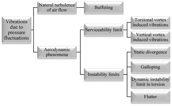
Figure 1.
Aerodynamic phenomena of suspension bridges.
3. Vortex Shedding Vibration
Vortex shedding causes bridges to vibrate in vertical and torsion degrees of freedom. VIV will be remarkable around the natural frequencies of bridge modes; it can be considered as a narrow-band frequency process. In fact, when the corresponding frequency of vortices is equal (or nearly equal) to the bridge modes frequency, the vibrations will be seen in larger amplitude. Thus, there is a certain velocity for each mode that resonance occurs in that.
where , , and are the mode frequency, depth of deck, and Strouhal number, respectively.
As VIV is the narrow band process, it is rational to evaluate the bridge response in certain modes. Thus, lower modes should be more accurately studied. As mentioned, the total response is divided into the static and dynamic parts, such that the mean value of the dynamic response is zero. In this regard, the auto spectral density of response () and its variance () can be written as follows:
where and signify the vertical and torsional degrees of freedom, respectively. In addition, , and denote the frequency, mode shape, and position in which the computation is done in there, respectively. The normalized frequency response function () and normalized auto spectral density of wind load () are as follows:
where and are the length of the bridge experiencing the vortex inducted loads and the non–dimensional coherence length scale of vortices, respectively. In addition, is modal mass. The aerodynamic damping () can be evaluated by the following relation:
where is the modally equivalent and evenly distributed mass:
In addition, the auto spectral density of the load may be evaluated by the following relation:
where , , , and are the air density, wind velocity, width of the deck, and bandwidth parameters. In addition, the standard deviation of load can be written as follows:
4. The Considered Bridge
The Halsafjorden suspension bridge, planned by the Norwegian Public Roads Administration (NPRA), aims to connect the west side of the fjord to Akvik on the east. Concrete towers, standing 265 m tall, support the main span on both sides, with cables extending down to rock anchor blocks across a 410-m side span. The cables have a sag of 205 m, resulting in a sag ratio of 0.1. The main cables possess a tensile strength of 1860 MPa, and each has a constructive steel area of A = 375 cm2. Hangers are spaced 30 m apart.
The deck features a twin box girder design, selected for its advantageous aerodynamic characteristics. Each box girder has a height of 2.5 m, a width of 11 m, and an area of 0.4430 m2, while the gap between them measures 10 m. Transverse stiffened steel girders, with a height of 2.5 m, a width of 1.5 m, and a constructive steel area of 0.132 m2, connect the two box girders. These transverse girders align with the hangers and are positioned at 30-m intervals along the bridge span. The bridge’s configuration and cross-section can be seen in Figure 2 and Figure 3, while Table 1 presents the bridge’s structural and geometrical property specifications.
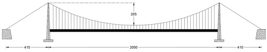
Figure 2.
In-plane view of the considered bridge (Dimensions in m).
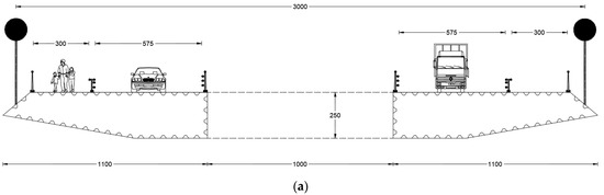
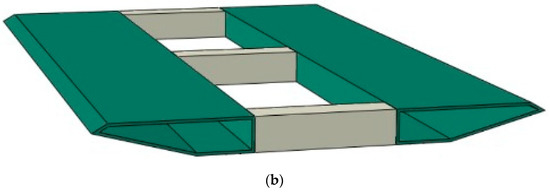
Figure 3.
Cross-section of the considered bridge, (a) Geometry of the deck (Dimensions in m), and (b) Configuration of the deck.

Table 1.
Structural and geometrical specifications of considered bridge.
To assess the bridge’s dynamic properties, the FEM is employed to calculate the structural properties matrices. The bridge is divided into 100 specific finite elements for this purpose. Each finite element consists of two nodes at its endpoints, with multi degrees of freedom including bending rotation, torsional rotation, vertical displacement, and warping as illustrated in Figure 4. Lavasani et al. [14] provide a detailed explanation of the computation process, and the dynamic specifications of the bridge are presented in Table 2. In Table 2, TS and TA denote the torsional symmetric and torsional antisymmetric mode shape of the bridge, respectively. To investigate the VIV, the flutter derivatives of the bridge are needed, as depicted in Figure 5.
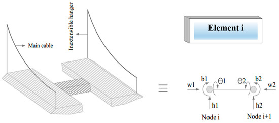
Figure 4.
Finite element of the suspension bridge model.
Table 2.
Mode shapes, frequencies, and periods of considered bridge.
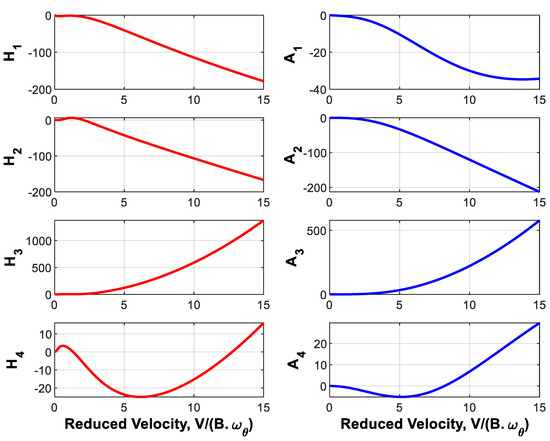
Figure 5.
Flutter derivatives of the considered bridge.
TMD Device
Tuned mass dampers have been widely employed in numerous studies for vibration control [26,36,37,38,39,40,41,42,43], with their straightforward design process and low maintenance costs being their key attributes. On the other hand, their downsides include high sensitivity to mistuning, significant space requirements for installation, and an inability to adapt their parameters to dynamic applied loads. Nonetheless, TMDs are often the first choice for mitigating vibrations in structures, both in research and practical applications. Typically, TMDs are configured to target a specific mode (usually the lower one) to dissipate incoming dynamic energy through their dampers [37]. Adjusting parameters such as mass ratio, damping ratio, and tuning frequency is crucial during the design process. Consequently, these parameters must be set to optimal values, which can be determined through an optimization process.
A too-heavy mass ratio causes considerable static deformations and changes the natural dynamic specifications. On the other hand, a light mass block does not have enough efficacy. The damping ratio should be adjusted to values, allowing free movement of the mass block. The tuning frequency may be named as the most sensitive parameter of it. As a simple way to overcome this problem, instead of tuning the TMD to a certain mode, it is rational to tune it to a ratio of a certain value that may involve the other vulnerable close modes. In this regard, the prone modes should be determined, and then an optimal ratio can be provided. The demonstration of attachment of TMD to the considered bridge is demonstrated in Figure 6. According to Figure 6, two masses are attached to the bottom of the section on the outside.
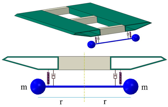
Figure 6.
Details of TMD installation.
5. Numerical Analysis
In this paper, the torsional VIV of the considered bridge is controlled by TMD. In this regard, some parameters are used for evaluating the wind-corresponding functions, provided in Table 3. To reach a comparative view, the uncontrolled responses should be evaluated. Regarding the narrow band frequency process, the resonance velocity of each mode and its corresponding response are required. In terms of the considered bridge, computations indicate that the first six modes expose high amplitude vibrations compared to other ones, shown in Figure 7, Figure 8 and Figure 9. In fact, the higher modes are not vulnerable to VIV.
Table 3.
Wind properties.
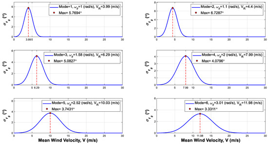
Figure 7.
The standard deviation of six initial modes.
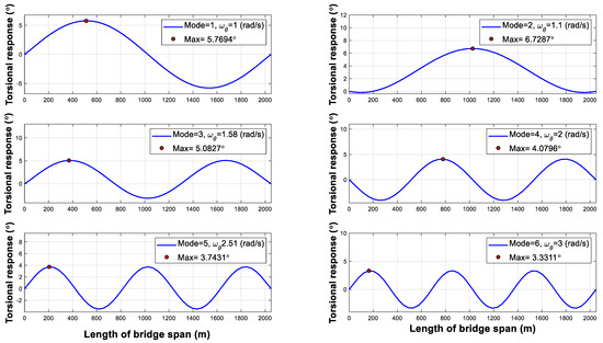
Figure 8.
Total response of the bridge.
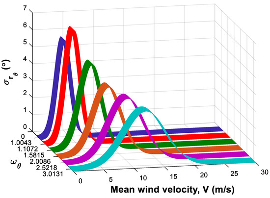
Figure 9.
Order and magnitude of six initial modes along the wind velocity.
Figure 9 shows that the first and second modes experience higher amplitude vibrations, disturbing the serviceability limit. Thus, the mode shapes of these modes determine the placement of TMDs. According to Figure 7, , and are the most important points. Mentioned points also undergo almost high amplitudes in the other modes. Thus, the analysis is conducted according to two following conditions:
- (a)
- One TMD is placed at the middle point.
- (b)
- Two TMDs are placed at the and points.
In each case, its parameters behavior is addressed by sensitivity analysis, and the related curvatures will be interpreted.
5.1. Mass Polar Moment of Inertia
The mass polar moment of inertia involves two primary parameters: mass ratio and the distance between the mass and the rotation axis, which determine the distribution of mass around the rotation axis. In this context, this distance is referred to as the distance factor (r). The optimization process aims to achieve the lightest mass with an appropriate distribution around the rotation axis. For this purpose, r is assumed to be 1, and the sensitivity of the mass ratio is examined based on the standard deviation of the midpoint (L/2) and the point with the maximum torsional response across the entire span. It is important to note that adding a TMD may alter the location of the maximum response. Figure 10 depicts the relevant curvatures for the mass ratio.
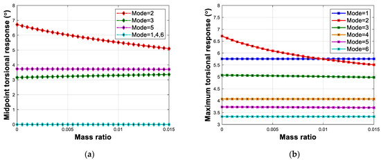
Figure 10.
Variation of the maximum torsion of (a) point and (b) whole span, in relation to the mass ratio, in the one TMD condition.
According to Figure 10, the maximum corresponding response of uncontrolled VIV in the middle point and whole span is the same as and equal to 6.72 degrees. In Figure 10a, by increasing the mass ratio, the middle point responses of the second mode were decreased by an appropriate slope, while the other modes’ corresponding responses have stayed unchangeable. In Figure 10b, the maximum response of the whole bridge in the second mode has been decreased by an increment of mass ratio. Comparing Figure 10a,b indicates that the local and total performance of TMD is 25.5 (6.72 was decreased to 5 degrees) and 18 (6.72 was decreased to 5.5 degrees) percent, respectively. Hence, the local performance of TMD is more suitable than its total performance. In addition, another distinguishing feature of the Figure is that although TMD cannot reduce VIV-related responses of other modes, it does not increase them.
Now, the computations are carried on by investigating the effects of the distance factor. In this regard, Figure 11 demonstrates the related curvatures of it.
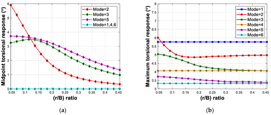
Figure 11.
Variation of the maximum torsion of (a) L/2 point and (b) whole span, in relation to the distance factor, in the one TMD condition.
In the horizontal axis of Figure 11, , signifying distance factor to deck width ratio, is utilized rather than . This ratio may provide more practical considerations. Figure 11a shows the maximum response of the middle point in the second mode, 6 degrees, is decreasing by an increment of . The gradient of the second mode curvatures has been decreased by an increment of , revealing there is a certain value that after it the increment of is not too effective. Here, the mentioned value is 0.25. Mode three curvature is similar to mode five, and a little ascending has been seen in the initial part of it. Figure 11b shows that the appropriate range of is 0.1 up to 0.2. Like the mass ratio parameter, the local performance of TMD () is too better than the total performance of it ).
Comparing Figure 10 and Figure 11 discloses that the parameter can reduce the other modes’ responses, or vice versa to mass ratio that cannot change the other modes’ responses.
Figure 12 and Figure 13 demonstrate the sensitivity of responses in relation to the variation of mass ratio and distance factor for the two TMDs condition.
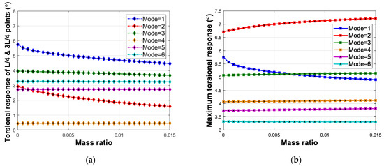
Figure 12.
Variation of the maximum torsion of (a) and points and (b) whole span, in relation to the mass ratio, in the two TMDs condition.
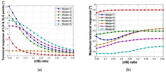
Figure 13.
Variation of the maximum torsion of (a) and points and (b) whole span, in relation to the distance factor, in the two TMDs condition.
Figure 12a displays the main role of mass ratio in response reduction of first and second modes corresponding responses. Figure 12b shows that by increasing the mass ratio, the second-mode responses are intensified, while first-mode ones are decreased. Hence, two TMDs, located at the and points, provide positive local performance in all considered modes; however, their total one is not positive for all modes.
5.2. Damping Ratio
In order to investigate the sensitivity of VIV against the damping ratio, it changes in the 0 up to 20% range, demonstrated in Figure 14. In addition, the mass ratio and distance factor are considered 1% and 0.2, respectively, for both one and two TMD conditions.
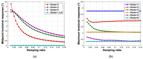
Figure 14.
Variation of the maximum torsion of (a) point and (b) whole span, in relation to the damping ratio, in the one TMD condition.
Figure 14a discloses that by increasing the damping ratio the point corresponding responses in modes two, three, and five are considerably reduced. Of course, the second mode response reduction gradient is too high compared to other ones in the 0 up to 10 percent range. Figure 14b indicates that the effect of the damping ratio on the maximum response of the whole bridge is too low compared to any certain point like . Especially, for mode two, the local performance of TMD is 90% (, while the total one is 7.6% (). Thus, the damping ratio parameter is effective in the local performance of TMD, and its total efficacy is nuance.
Figure 15 demonstrates the sensitivity of responses in relation to the variation of damping ratio for the two TMDs condition.
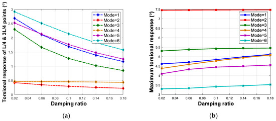
Figure 15.
Variation of the maximum torsion of (a) and points and (b) whole span, in relation to the damping ratio, in the two TMDs condition.
Like the one TMD condition, the damping ratio renders suitable local performance, and its appropriate range is 0 up to 10 percent.
5.3. Frequency Ratio
According to mentioned contents of the former sections, the mistuning of TMD can considerably decline the efficacy of it. In this regard, the responses should be addressed in a range around a certain mode frequency. Figure 16 shows the VIV corresponding response in the 0.7 up to 1.4 variations of the frequency ratio. The mass ratio, the r/B, and the damping ratio are 1%, 0.2, and 10%, respectively.
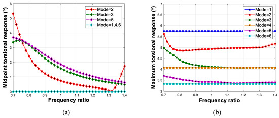
Figure 16.
Variation of the maximum torsion of (a) point and (b) whole span, in relation to the frequency ratio, in the one TMD condition.
Figure 16a reveals that the corresponding responses of point are declined by the increment of the frequency ratio. The final part of the second mode’s corresponding curvature indicates that when the tuning frequency deviates considerably from the frequency of the modes, unfavorable effects will emerge. Figure 16a,b display that after the maximum response of the whole span and point will be increased.
Figure 17 demonstrates the sensitivity of responses in relation to the variation of frequency ratio for the two TMDs condition. It is worth noting that the mass ratio, , and damping ratio are considered 1%, 0.2, and 10%, respectively.
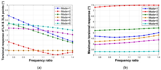
Figure 17.
Variation of the maximum torsion of (a) and points and (b) whole span, in relation to the frequency ratio, in the two TMDs condition.
A similar statement of the one TMD condition can be expressed for the two TMDs. It is worth noting that one TMD is tuned to the second mode, and two TMDs are tuned to the first mode.
5.4. Combined Condition
There, TMDs whose appropriate parameters were achieved using genetic algorithm and sensitivity analysis were attached to , and points to reduce the VIV responses are provided in Table 4 and Table 5.
Table 4.
Optimum parameter of TMD reached by genetic algorithm.
Table 5.
Optimum parameter of TMD reached by sensitivity analysis.
The middle point TMD parameters are adjusted according to the second mode, and two other ones obey the first mode specifications. Figure 18 and Figure 19 show the standard deviation of the critical point of each mode and the total response of the bridge in uncontrolled and controlled conditions, respectively.
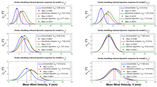
Figure 18.
Standard deviation in uncontrolled and controlled conditions.
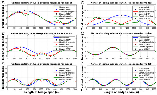
Figure 19.
Total response of bridge in uncontrolled and controlled conditions.
Figure 18 indicates that TMD can successfully reduce the standard deviation of critical points. There is a little increment in mode four, which is negligible. Thus, the local performance of TMD is better in lower modes and has not had a negative role in the other modes. In addition, the parameters achieved by sensitivity analysis provide better performance than genetic algorithm ones.
For addressing the performance of TMD in response to reduction during the time, the following relation can be utilized:
where is arbitrary phase angles between zero and 2π, is the frequency segment, and is the middle point of each segment.
Figure 20 and Figure 21 show the time history of torsional responses. Figure 20 and Figure 21 show that TMDs successfully mitigate the VIV in considered modes.
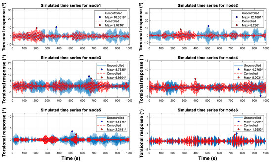
Figure 20.
Time history of torsional response at the 4 velocity at each mode critical point.
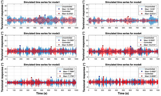
Figure 21.
Time history of torsional response at the resonance velocity of each mode at its critical point.
6. Conclusions
In this paper, the torsional VIV of an ultra-span twin box girder suspension bridge, with a 2050 span length, was controlled by TMDs. Firstly, VIV analysis of the bridge was done to determine the vulnerable modes that were the six initial ones. The parameters of TMD named mass ratio, distance factor, damping ratio, and frequency ratio were investigated under VIV to achieve their optimum ranges. A sensitivity analysis was conducted according to each mode critical point and the maximum response along the span. After computing the appropriate parameters by sensitivity analysis and genetic algorithm, the torsional VIV was controlled and comparisons were made. The most important results are as follows:
The mass polar moment of inertia should be optimized in two independent phases, including mass ratio and distribution of mass around the torsion axis. Increment of mass ratio and improve the local and total performance of TMD, and increment of has a stronger impression on the local performance in comparison to the total one. The has the most integral role in reducing the vulnerable modes in comparison to the mass ratio. The appropriate range of mass ratio and are 0.5 up to 1.5 percent and 0.15 up to 0.2, respectively.
For improving the local performance, by moving away from the middle point, the mass blocks become lighter, and their distance increase. The TMD, located at the middle point, has the most weight, and the distance of its mass block is the minimum. The better total performance needs heavier mass blocks placed closer to each other.
The damping ratio has perfectly local performance, and its total efficacy is nuance. Its optimum range is 0 up to 10 percent.
The increment of frequency ratio increases the local and total efficacy of TMD such that the local one is more sensible. The optimum range of it is 1 up to 1.3 times to the considered mode. A higher value of 1.3 causes unfavorable results.
For the considered bridge, attaching three TMDs to , and points, comprising a 1% mass ratio, 0.15 , 10% damping ratio, and 1.25 frequency ratio, decreased the maximum response, 6.72°, to 4.42°, indicating a 34% response reduction. The considered TMDs suitably mitigated the vibration amplitude during the resonance velocity of vulnerable modes preventing the occurrence of fatigue damage in the long term.
Author Contributions
Conceptualization, S.H.H.L. and D.-P.N.K.; methodology, S.H.H.L. and D.-P.N.K.; software, S.H.H.L., D.-P.N.K., H.A. and V.G.; validation, S.H.H.L., D.-P.N.K., H.A. and V.G.; formal analysis, S.H.H.L. and D.-P.N.K.; investigation, S.H.H.L., D.-P.N.K., H.A. and V.G.; resources, S.H.H.L. and D.-P.N.K.; data curation, S.H.H.L., D.-P.N.K., H.A. and V.G.; writing—original draft preparation, S.H.H.L., D.-P.N.K., H.A. and V.G.; writing—review and editing, S.H.H.L. and D.-P.N.K.; visualization, S.H.H.L., D.-P.N.K., H.A. and V.G.; supervision, S.H.H.L. and D.-P.N.K.; project administration, D.-P.N.K. All authors have read and agreed to the published version of the manuscript.
Funding
This research received no external funding.
Institutional Review Board Statement
Not applicable.
Informed Consent Statement
Not applicable.
Data Availability Statement
Data are available within the article.
Conflicts of Interest
The authors declare no conflict of interest.
References
- Alizadeh, H.; Lavassani, S.H.H. Flutter Control of Long Span Suspension Bridges in Time Domain Using Optimized TMD. Int. J. Steel Struct. 2021, 21, 731–742. [Google Scholar] [CrossRef]
- Alizadeh, H.; Hosseini Lavassani, S.H. The effect of soil-structure interaction on longitudinal seismic responses of suspension bridges controlled by optimal TMD. J. Struct. Constr. Eng. 2022, 8, 439–458. [Google Scholar] [CrossRef]
- Hosseini Lavassani, S.H.; Alizadeh, H.; Doroudi, R.; Homami, P. Vibration control of suspension bridge due to vertical ground motions. Adv. Struct. Eng. 2020, 23, 2626–2641. [Google Scholar] [CrossRef]
- Basu, R.; Vickery, B. Across-wind vibrations of structure of circular cross-section. Part II. Development of a mathematical model for full-scale application. J. Wind Eng. Ind. Aerodyn. 1983, 12, 75–97. [Google Scholar] [CrossRef]
- Fujino, Y.; Yoshida, Y. Wind-induced vibration and control of Trans-Tokyo Bay crossing bridge. J. Struct. Eng. 2002, 128, 1012–1025. [Google Scholar] [CrossRef]
- Weber, F.; Maślanka, M. Frequency and damping adaptation of a TMD with controlled MR damper. Smart Mater. Struct. 2012, 21, 055011. [Google Scholar] [CrossRef]
- Gao, D.; Deng, Z.; Yang, W.; Chen, W. Review of the excitation mechanism and aerodynamic flow control of vortex-induced vibration of the main girder for long-span bridges: A vortex-dynamics approach. J. Fluids Struct. 2021, 105, 103348. [Google Scholar] [CrossRef]
- Park, J.; Kim, S.; Kim, H.-K. Effect of gap distance on vortex-induced vibration in two parallel cable-stayed bridges. J. Wind Eng. Ind. Aerodyn. 2017, 162, 35–44. [Google Scholar] [CrossRef]
- Wang, W.; Wang, X.; Hua, X.; Song, G.; Chen, Z. Vibration control of vortex-induced vibrations of a bridge deck by a single-side pounding tuned mass damper. Eng. Struct. 2018, 173, 61–75. [Google Scholar] [CrossRef]
- Xue, Z.; Han, B.; Zhang, H.; Xin, D.; Zhan, J.; Wang, R. External suction-blowing method for controlling vortex-induced vibration of a bridge. J. Wind Eng. Ind. Aerodyn. 2021, 215, 104661. [Google Scholar] [CrossRef]
- Li, K.; Ge, Y.; Guo, Z.; Zhao, L. Theoretical framework of feedback aerodynamic control of flutter oscillation for long-span suspension bridges by the twin-winglet system. J. Wind Eng. Ind. Aerodyn. 2015, 145, 166–177. [Google Scholar] [CrossRef]
- Bai, H.; Ji, N.; Xu, G.; Li, J. An alternative aerodynamic mitigation measure for improving bridge flutter and vortex induced vibration (VIV) stability: Sealed traffic barrier. J. Wind Eng. Ind. Aerodyn. 2020, 206, 104302. [Google Scholar] [CrossRef]
- Zhou, R.; Ge, Y.; Liu, Q.; Yang, Y.; Zhang, L. Experimental and numerical studies of wind-resistance performance of twin-box girder bridges with various grid plates. Thin-Walled Struct. 2021, 166, 108088. [Google Scholar] [CrossRef]
- Hosseini Lavassani, S.H.; Alizadeh, H.; Homami, P. Optimizing tuned mass damper parameters to mitigate the torsional vibration of a suspension bridge under pulse-type ground motion: A sensitivity analysis. J. Vib. Control 2020, 26, 1054–1067. [Google Scholar] [CrossRef]
- Elias, S.; Matsagar, V. Research developments in vibration control of structures using passive tuned mass dampers. Annu. Rev. Control. 2017, 44, 129–156. [Google Scholar] [CrossRef]
- Frahm, H. Device for Damping Vibrations of Bodies. US Patent US989958A, 30 October 1909. [Google Scholar]
- Den Hartog, J.; Ormondroyd, J. Theory of the dynamic vibration absorber. ASME J. Appl. Mech. 1928, 50, 11–22. [Google Scholar]
- Kwon, S.-D.; Jung, M.S.; Chang, S.-P. A new passive aerodynamic control method for bridge flutter. J. Wind Eng. Ind. Aerodyn. 2000, 86, 187–202. [Google Scholar] [CrossRef]
- Gu, M.; Chen, S.; Chang, C. Control of wind-induced vibrations of long-span bridges by semi-active lever-type TMD. J. Wind Eng. Ind. Aerodyn. 2002, 90, 111–126. [Google Scholar] [CrossRef]
- Pourzeynali, S.; Datta, T. Control of flutter of suspension bridge deck using TMD. Wind Struct. 2002, 5, 407–422. [Google Scholar] [CrossRef]
- Chen, X.; Kareem, A. Efficacy of tuned mass dampers for bridge flutter control. J. Struct. Eng. 2003, 129, 1291–1300. [Google Scholar] [CrossRef]
- Chen, S.; Cai, C. Coupled vibration control with tuned mass damper for long-span bridges. J. Sound Vib. 2004, 1, 449–459. [Google Scholar] [CrossRef]
- Abdel-Rohman, M.; John, M.J. Control of wind-induced nonlinear oscillations in suspension bridges using a semi-active tuned mass damper. J. Vib. Control 2006, 12, 1049–1080. [Google Scholar] [CrossRef]
- Domaneschi, M.; Martinelli, L.; Po, E. Control of wind buffeting vibrations in a suspension bridge by TMD: Hybridization and robustness issues. Comput. Struct. 2015, 155, 3–17. [Google Scholar] [CrossRef]
- Alizadeh, H.; Lavassani, S.H.H.; Pourzeynali, S. Flutter Instability Control in Suspension Bridge by TMD. In Proceedings of the 11th International Congress on Civil Engineering, Tehran, Iran, 8–10 May 2018. [Google Scholar]
- Kontoni, D.-P.N.; Farghaly, A.A. Mitigation of the seismic response of a cable-stayed bridge with soil-structure-interaction effect using tuned mass dampers. Struct. Eng. Mech. 2019, 69, 699–712. [Google Scholar] [CrossRef]
- Mansouri, S.; Kontoni, D.-P.N.; Pouraminian, M. The effects of the duration, intensity and magnitude of far-fault earthquakes on the seismic response of RC bridges retrofitted with seismic bearings. Adv. Bridge Eng. 2022, 3, 19. [Google Scholar] [CrossRef]
- Patil, V.B.; Jangid, R.S. Optimum multiple tuned mass dampers for the wind excited benchmark building. J. Civ. Eng. Manag. 2011, 17, 540–557. [Google Scholar] [CrossRef]
- Bandivadekar, T.; Jangid, R. Optimization of multiple tuned mass dampers for vibration control of system under external excitation. J. Vib. Control 2013, 19, 1854–1871. [Google Scholar] [CrossRef]
- Wang, Y.; Feng, C.; Chen, S. Damping effects of linear and nonlinear tuned mass dampers on nonlinear hinged-hinged beam. J. Sound Vib. 2018, 430, 150–173. [Google Scholar] [CrossRef]
- Shi, W.; Wang, L.; Lu, Z.; Wang, H. Experimental and numerical study on adaptive-passive variable mass tuned mass damper. J. Sound Vib. 2019, 452, 97–111. [Google Scholar] [CrossRef]
- Dai, J.; Xu, Z.-D.; Gai, P.-P.; Xu, Y.W. Mitigation of vortex-induced vibration in bridges using semi active tuned mass dampers. J. Bridge Eng. 2021, 26, 05021003. [Google Scholar] [CrossRef]
- Ubertini, F.; Comanducci, G.; Laflamme, S. A parametric study on reliability-based tuned-mass damper design against bridge flutter. J. Vib. Control 2015, 23, 1518–1534. [Google Scholar] [CrossRef]
- Pisal, A.Y.; Jangid, R.S. Vibration control of bridge subjected to multiaxle vehicle using multiple tuned mass friction dampers. Int. J. Adv. Struct. Eng. 2016, 8, 213–227. [Google Scholar] [CrossRef]
- Tao, T.; Wang, H.; Yao, C.; He, X. Parametric sensitivity analysis on the buffeting control of a long-span tripletower suspension bridge with MTMD. Appl. Sci. 2017, 7, 395. [Google Scholar] [CrossRef]
- Strømmen, E. Theory of Bridge Aerodynamics; Springer Science & Business Media: Berlin/Heidelberg, Germany, 2010. [Google Scholar] [CrossRef]
- Amini, F.; Doroudi, R. Control of a building complex with magneto-rheological dampers and tuned mass damper. Struct. Eng. Mech. 2010, 36, 181–195. [Google Scholar] [CrossRef]
- Bortoluzzi, D.; Casciati, S.; Elia, L.; Faravelli, L. Design of a TMD solution to mitigate wind-induced local vibrations in an existing timber footbridge. Smart Struct. Syst. 2015, 16, 459–478. [Google Scholar] [CrossRef]
- Debbarma, R.; Das, D. Vibration control of building using multiple tuned mass dampers considering real earthquake time history. Int. J. Civ. Environ. Eng. 2016, 10, 694–704. [Google Scholar]
- Kontoni, D.-P.N.; Farghaly, A.A. Enhancing the earthquake resistance of RC and steel high-rise buildings by bracings, shear walls and TMDs considering SSI. Asian J. Civ. Eng. 2023. [Google Scholar] [CrossRef]
- Kontoni, D.-P.N.; Farghaly, A.A. The effect of base isolation and tuned mass dampers on the seismic response of RC high-rise buildings considering soil-structure interaction. Earthq. Struct. 2019, 17, 425–434. [Google Scholar] [CrossRef]
- Kontoni, D.-P.N.; Farghaly, A.A. TMD effectiveness for steel high-rise building subjected to wind or earthquake including soil-structure interaction. Wind Struct. 2020, 30, 423–432. [Google Scholar] [CrossRef]
- Hosseini Lavassani, S.H.; Shangapour, S.; Homami, P.; Gharehbaghi, V.; Farsangi, E.N.; Yang, T.Y. An innovative methodology for hybrid vibration control (MR + TMD) of buildings under seismic excitations. Soil Dyn. Earthq. Eng. 2022, 155, 107175. [Google Scholar] [CrossRef]


Disclaimer/Publisher’s Note: The statements, opinions and data contained in all publications are solely those of the individual author(s) and contributor(s) and not of MDPI and/or the editor(s). MDPI and/or the editor(s) disclaim responsibility for any injury to people or property resulting from any ideas, methods, instructions or products referred to in the content. |
© 2023 by the authors. Licensee MDPI, Basel, Switzerland. This article is an open access article distributed under the terms and conditions of the Creative Commons Attribution (CC BY) license (https://creativecommons.org/licenses/by/4.0/).