Abstract
Complex edge stiffeners are widely used because of their superior performance over simple edge stiffeners in limiting flange buckling and improving local stability. However, most of the studies on complex edge stiffeners are qualitative. In this paper, the criterion to judge the stiffening adequacy based on the buckling half-wavelength and buckling coefficient is proposed. It is considered as the criterion that the edge stiffeners’ stiffness is not less than the minimum stiffening stiffness or the half-wavelength of buckling is not more than the width of the flange. The criterion is followed for the minimum limits of the edge stiffener width−thickness ratios; whether the flange buckling occurs before the edge stiffener buckling and the economic implications are the criteria that should be followed for the maximum limits of the edge stiffener width−thickness ratios. Using the finite strip method, the feasibility of the criteria was verified by comparing them with the rules of simple edge stiffeners. The detailed design requirements for the width−thickness ratio limits of thin-walled steel elements with complex edge stiffeners were first given from an extensive parametric analysis. Based on the optimization algorithm, the suggestions and optimum sizes of complex edge stiffeners for thin-walled steel elements are provided, considering the sections’ economy and performance. It is considered that a ratio of 1:1 between the primary and the secondary edge stiffeners’ widths is the best configuration for elements with complex edge stiffeners.
1. Introduction
Cold-formed steel (CFS) is widely used in many countries in structural and non-structural members due to its high strength-to-weight ratio and low cost of material and manufacture [1]. Buckling refers to a type of structural failure where a compressed member, such as a cold-formed steel section, suddenly bends or collapses under an applied load. As thin-walled sections become increasingly complex, the issue of buckling becomes more serious. An edge stiffener is a structural component that is attached to the edge of a thin-walled steel element to provide additional support and improve its stability. The edge stiffener width−thickness ratio and the edge stiffeners’ form strongly influence the element’s buckling performance and can even affect its buckling mode [2]. If the edge stiffeners of open cross-section thin-walled steel elements do not have folds, they will have poor local stability. Simple edge stiffeners consisting of a single lip at the free edge provide substantial benefits, but when the lip becomes too long, it may buckle first and cause instability. To improve the elements’ stability, the edge stiffeners must be stiffened moderately. Hence, thin-walled steel elements with complex edge stiffeners have emerged, which can alleviate this instability by providing additional folds to the lip itself [3]. As shown in Figure 1, the shear center will be far away from the flange−stiffener juncture when the simple edge stiffeners are folded inward. As the distortional buckling mainly occurs near the flange−stiffener juncture, multiple folds can improve the ultimate bearing capacity of the element [4]. Therefore, an improvement of the stiffening form at the edge stiffeners is a vital way to limit the buckling of flanges and enhance the mechanical properties of the section.
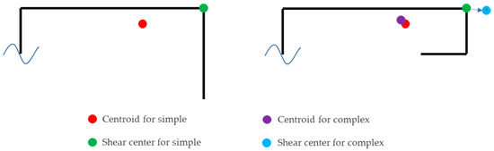
Figure 1.
Geometric features of the flange and edge stiffeners.
For a long time, scholars worldwide have done a lot of research on the design of thin-walled sections and have given their opinions on the design of simple edge stiffeners. Starting in 1939, Winter [5] did a lot of experiments on CFS and explored the performance of simple edge stiffeners. In 1978, Desmond et al. [6] gave a criterion for determining whether an edge stiffener needs to be stiffened and a simplified formula for calculating the minimum stiffness limits by theoretical analysis. They concluded that stiffener adequacy is assessed using stiffener rigidity, for which the ultimate strength of an edge-stiffened element equals that of an element of similar dimensions and material properties but supported by a web at the stiffener location [7]. Based on the research in [8,9], the post-buckling properties were studied by Sarawit et al. [10]. The ultimate strength of an element with different degrees of imperfections was found, and the percent difference in strength was introduced to analyze the imperfection sensitivity. Bambach [11] carried out geometric and material non-linear finite element analysis on about 200 edge-stiffened elements and analyzed the basic properties of elements with three sides simply supported and one side stiffened. It was shown that a buckling coefficient k ≥ 4 indicates that the element is sufficiently stiffened. Bambach [12] investigated the buckling behavior of stiffened elements by conducting compression tests on 30 edge-stiffened elements, gave the limiting conditions for simple edge stiffeners, and modified the strength calculation equations. A series of axial compression tests were conducted on simple edge columns constructed from high strength Grade G550 steel sheet of thickness 1 mm by Huang et al. [13]. By parametric analysis, it was found that the edge width has a great influence on the bearing capacity of specimens because of the significant restriction of edge stiffeners on distortional deformation. Guo et al. [14] presented a total of 44 axially compressed tests of CFS lipped channel columns including different cross-sections. The validated FE model was used to conduct a parametric study to investigate the effects of the section on the ultimate strength of such channels. To improve the bearing capacity of cold-formed Z-section steel members, Ye et al. [15] optimized the design of its edge stiffener inclination, suggesting that the design inclination of the edge stiffener should be 100° in practical engineering.
Some studies on complex edge stiffeners have also been carried out. In 1993, Seah et al. [16] investigated the buckling performance of thin-walled elements with complex edge stiffeners under axial pressure. They found that the complex edges’ cross-sectional performance was superior to simple edges. Schafer et al. [4] isolated the flanges and complex edge stiffeners as compressive elements and performed finite element analysis with supports instead of web effects to obtain approximate solutions. They concluded that the complex edge-stiffened elements have a more extensive application range than the simple ones and can provide better strength with slightly increased imperfection sensitivity. Xi et al. [3] conducted the tests about thin-walled elements with complex edge stiffeners and concluded that the load capacity of the inward complex edge stiffeners is significantly higher than the outward ones in elastic buckling. Du et al. [17] analyzed the buckling performance of thin-walled channel steel columns by SAP2000 and concluded that web-flange width ratios of between 1.1 and 1.4 significantly affected the critical buckling stress. Jiao et al. [18] used ABAQUS to analyze the buckling performance of thin-walled steel columns with solid struts at both ends. They explored the effects of edge stiffener form, height, and thickness on the buckling mode of steel columns under axial compression. They also concluded that the larger the web width is, the more significant the advantage of complex edge stiffeners is, and the greater the buckling load is when local buckling first occurs in the element. Zhang et al. [19] carried out a series of numerical and theoretical researches on cold-formed steel elements with complex edge stiffeners and developed a detailed non-linear finite element model (FEM) [20]. They also proposed a method to determine the critical stress of the complex edge section. Aruna et al. [21] investigate the axial compression capacity of CFS equal angle sections with complex edge stiffeners. Both experimental and numerical analyses were carried out, and these implied that the existing direct strength method (DSM) rules are over-conservative. Wang et al. [22] test a total of 16 pin-ended cold-formed steel columns. The ultimate load-carrying capacity and deformation behavior of cold-formed steel members with complicated cross-sections were studied. It was found that the loading efficiency of columns with complex edge stiffeners is higher than columns with simple edge stiffeners. Song et al. [23,24] studied columns with complex edge stiffeners and cap-shaped stiffeners. The effects of specimen length, the width−thickness ratio of the plates, section types, and the eccentric distance on stability were carried out. The buckling mode and deflection behavior of channel columns with complex edge stiffeners and cap-shaped stiffeners were investigated.
Currently, most of the research on complex edge stiffeners is qualitative, and the design of CFS always focuses on simple edge stiffeners but lacks relevant provisions for complex edge stiffeners. This paper analyzes and optimizes complex edge stiffeners based on the finite strip method (FSM) and related buckling theories. Firstly, the minimum limit criteria of the edge stiffeners were put forward by theoretical analysis. Secondly, the simple edge stiffeners’ limits required by AISI S100 [25] were used to verify the accuracy of these criteria. Next, as the norm for the limit value of simple edge stiffeners was obtained by considering defects based on experiments, the revision of the criterion was introduced according to the norm and applied to the analysis of complex edge stiffeners. The limits of the width−thickness ratio of the complex edge stiffeners were given based on axial compression elements and the FSM models under different steel components were tested for verification. Finally, the optimal width−thickness ratio and the optimal configuration of the complex edge stiffeners were found through the optimization algorithm, which provided suggestions for the subsequent design.
2. Estimate for Stiffener Adequacy
2.1. Model and Method
Schafer et al. [4] and Bambach et al. [11,12] emphasized the study of the flange with edge stiffeners. They believed that, by fixing the connection between the web and the flange, the buckling behavior and bearing capacity of the flange with one side simply supported and one side-stiffened plate can show its capacity in the whole section as well. In AISI S100 [25], AS/NZS 4600 [26], and Desmond et al. [6], the influence of different webs on the flange is no longer considered in the design method of the edge stiffener. Still, a simple formula for calculating the minimum stiffness limit of the flange is directly given. GB50018 [27] also only makes requirements for the width ratio relationship between the flange and edge stiffeners but does not involve the requirements for the web. Therefore, we can refer to Schafer’s method [4] to study the limit of complex edge stiffeners by ignoring the difference in the web effect, isolating the flange and complex edge stiffeners as compression components in the analysis, and using simple support to replace the web effect.
The FSM is widely regarded as an effective tool for the structural analysis and design of thin-walled elements [28]. The eigenvalue buckling analysis is based on the initial model of the structure and the small displacement linear theory, which can be used to predict the strength of thin-walled elements. Therefore, the FSM is a reliable numerical method to analyze complex edge-stiffened elements and to calculate the elastic critical buckling stress.
The yield strength fy = 355 MPa, elastic modulus E = 206,000 MPa, and Poisson’s ratio ν = 0.3 were used as the research object in the analysis. In AISI S100 [25] and AS/NZS 4600 [26], b/t shall not exceed 160. The flange width ratio b/t given in GB50018 [27] has been expanded to 15~60. EN1993-1-3 gives b/t ≤ 90 [29]. To ensure the applicability of the research results, 15 ≤ b/t ≤ 160 and 0 ≤ a/t ≤ b/t (a is the length of the edge stiffener and the total length of the complex edge stiffeners) are adopted as the parametric analysis range of the complex edge stiffener based on the FSM. The analysis model of simple edge-stiffened elements is shown in Figure 2, where a refers to the flange width; b refers to the edge stiffener width.
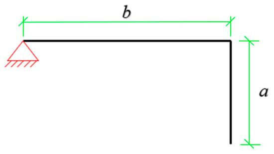
Figure 2.
Analytical model for the simple edge stiffener.
2.2. Limits Criterion
The limits on edge stiffeners are mainly to ensure local stability and improve the bearing capacity of the elements. Local buckling has a significant post-buckling strength reserve [30] and higher stability in the instability modes. Therefore, a criterion of limit value selection is to consider the deformation characteristics of flange buckling to ensure that the local buckling occurs first. The buckling half-wavelength is related to the buckling mode and represents the buckling deformation characteristics. Bambach et al. [11,12] gave the form of the fully stiffened element such that the flange buckles within a half-wavelength equal to the width of the flange and does not have movement at the flange−stiffener intersection. Therefore, the local buckling half-wavelength−thickness ratio, l/t ≤ b/t, can be used as one of the criteria for whether a simple edge stiffener is adequate.
The value of the critical buckling stress can be used to calculate the bearing capacity, and the calculation equation is as follows:
where t is the element thickness; b is the flange width; E is the elastic modulus; ν is Poisson’s ratio; and the buckling coefficient of elements simply supported on four sides, k0, equals 4. Referring to the critical buckling stress equation of the element, as shown in Equation (1), the buckling coefficient k can also be used as a criterion for judging the local buckling. When one side of the model is simply supported, based on the research of Desmond et al. [6], k ≥ k0 can be used as one of the criteria for sufficient stiffening of the edge in theory.
In short, the buckling form and local stability of the elements can be guaranteed by controlling the local buckling half-wavelength−thickness ratio l/t, and the bearing capacity of the elements can be guaranteed by controlling the buckling coefficient k. Both of these can indicate the adequacy of the stiffening and thus become the criterion for selecting the stiffener limit.
3. Verification of the Criterion on Simple Edge Stiffeners
3.1. Elastic Local Buckling Analysis of the Elements with Simple Edge Stiffeners
For simple edge-stiffened elements, parametric analysis of the simple edge stiffener isolator, shown in Figure 2, is carried out using the FSM. The relationship between the elastic local buckling half-wavelength−thickness ratio l/t, the buckling coefficient k, and the width−thickness ratio of edge stiffeners a/t under different flange width−thickness ratios b/t obtained by parametric analysis are shown in Figure 3 and Figure 4.
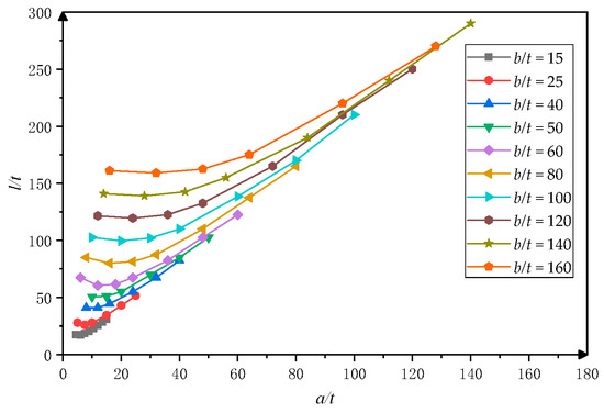
Figure 3.
Values of l/t for different simple edge stiffener width−thickness ratios.
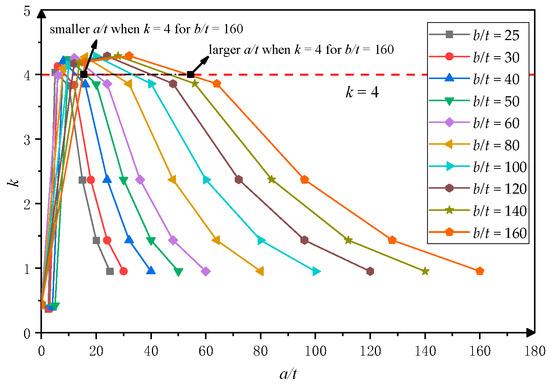
Figure 4.
Values of k for different simple edge stiffener width−thickness ratios.
As shown in Figure 3, under the same a/t, the larger b/t is, the larger l/t is. This is because the buckling property of the element is closely related to the flange width, and the value of l/t is positively related to the value of b/t. When the constraints are sufficient, the local buckling half-wavelength is approximately equal to the width of the flange. Under the same b/t, l/t tends to decrease and then increase as a/t increases. That is because the constraint effect on the flange is less when a/t is small. When a/t is too large, the edge will buckle first, which cannot provide enough constraint for the flange. An inadequate constraint will increase the buckling half-wavelength of the element.
As shown in Figure 4, the buckling coefficient k increases first with the increase of a/t and then decreases. That is because, when a/t is too small, the insufficiency of the edge width, which will drive it in its own plane like a compressive bar instability, makes the distortional buckling occur first. With the increase of a/t, the distortional buckling probability of the edge stiffeners is reduced, the probability of local buckling increases, and the edge stiffeners can offer enough support to improve the bearing capacity, which means the value of k increases. When a/t is too large, the edge stiffeners tend to buckle first, and the flanges are required to provide constraints for them, so the bearing capacity decreases and the k value decreases. Therefore, obtaining the limit of edge stiffeners through two criteria is reasonable.
3.2. Comparison of Criteria with AISI S100
The design requirements of uniformly pressurized elements with edge stiffeners from AISI S100 [25] and AS/NZS 4600 [26] follow the critical buckling criterion (CBC) and the ultimate strength criterion (USC): Is ≥ Ia, and a/b ≤ 0.8. Ia is calculated as follows:
where b is the flange width; t is the element thickness; S = 1.28; is the minimum adequate moment of inertia of the stiffener to make each component element behave as a stiffened element; is the moment of inertia of the stiffener about its own centroidal axis parallel to the element to be stiffened; = 0.43 is the buckling coefficient of the flange with one side simply supported and one side free. When the material is Q355, S = 30.83.
Based on the CBC, the simultaneous buckling of the flanges and edge stiffeners is considered as the critical state for sufficient stiffening. Based on the USC, it is believed that the ultimate strength of the fully stiffened flange is equal to that of the flange with web support on both sides. Since the analytical model used treats the web action as simply supported, the buckling coefficient of the edge-stiffened element k = k0 is the result that follows the CBC and USC requirements. The simple edge stiffener isolator shown in Figure 2 is parametrically analyzed using the FSM and compared with AISI S100-2016 [25] to explore how the limits in the norm are selected. The values of a/t under different b/t values are obtained by Equations (2)–(4) and = a3t/12 (the inertia moment formula of simple edge stiffeners), and the corresponding k and l/t are obtained by the FSM, which are shown in Table 1.

Table 1.
a/t, k, and l/t obtained from Equations (2)–(4) and b/t.
Comparing the AISI S100 [25] results shown in Table 1 with the criterion, the differences between the l/t and b/t values are insignificant. It is considered that l/t = b/t can be adopted as the edge stiffening minimum limit requirement. The results in Table 1 also show that AISI S100 [25] follows the CBC and USC in selecting the minimum stiffening. The critical buckling stress of the analyzed model is not lower than that of a four-sided simply supported plate with the same size, i.e., k ≥ 4. The ranges of the errors between the criteria and the norms were 0.75–6.50% and 0–10%, respectively, which indicated that the criterion was feasible.
Complex edge stiffeners are shown to provide improved ultimate strength performance over simple stiffeners, but with a slight increase in imperfection sensitivity [4]. Therefore, in order to ensure safety, l/t = b/t, and k = 4.26 (the maximum value in Table 1) are taken as the criteria, considering the influence of defects. At this time, the average relative errors with the norms are 2.36% and 1.69%, respectively.
4. Complex Edge Stiffener Limits
For the minimum limits of the edge stiffeners, each country norm gives the requirements for the stiffeners’ minimum adequate moment of inertia. However, the solution of the moment of inertia for complex edge stiffeners with various forms is more complicated and lacks a unified calculation formula. This paper refers to the selection of simple edge stiffener limit values and it is believed that it is more convenient and intuitive to propose a table or a simplified calculation equation based on the value of l/t or k.
4.1. Elastic Local Buckling Analysis of the Element with Complex Edge Stiffeners
The analysis method for the complex edge stiffeners is borrowed from the simple ones. Referring to the research by Schafer et al. [4], the flange and the edge stiffener as a compressed component element are isolated with the support instead of the web role, and one side is regarded as simply supported, as shown in Figure 5, where b is the flange width, a1 is the primary edge stiffener’s width, a2 is the secondary edge stiffener’s width, and the total width of the edge stiffeners is a = a1 + a2. Referring to the relevant research and FSM results shown in Figure 6, when the flange width is small, the elements with complex edge stiffeners have a lower distortional critical buckling stress. Distortional buckling is more likely to occur at this time, and the bearing capacity is smaller than that of the same size of simple edge stiffeners. Hence, the simple edge stiffener has more significant advantages than complex ones at smaller b/t. Therefore, in this study, the range of b/t is 15~160 for simple edge stiffeners, and the range of b/t is 25~160 for complex edge stiffeners.
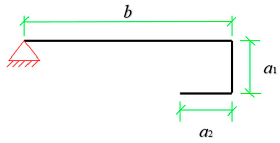
Figure 5.
Analytical model for the complex edge stiffener.
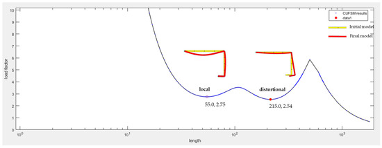
Figure 6.
Complex edge stiffener signature curve for a2:a1 = 0.25.
The complex edge stiffener form is divided into four types, as shown in Figure 7, for parametric analysis. Based on the FSM, the relationship between l/t and a/t is obtained as shown in Figure 8. Referring to Equation (1), the relationship between k and a/t is obtained as shown in Figure 9.
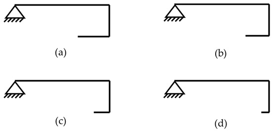
Figure 7.
Complex edge stiffeners with different proportions: (a) a2:a1 = 1; (b) a2:a1 = 0.75; (c) a2:a1 = 0.5; (d) a2:a1 = 0.25.
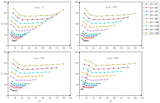
Figure 8.
Values of l/t of the complex edge stiffeners for different a2/a1 ratios.
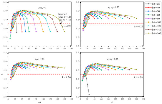
Figure 9.
Values of k of the complex edge stiffeners for different a2/a1 ratios.
When a/t and b/t are the same, the half-wavelength of the complex edge stiffeners is smaller than that of the simple one, and the range less than the width of the flanges is larger, as shown in Figure 3 and Figure 8. When the flange is constrained sufficiently, the local buckling half-wavelength is approximately equal to the width of the flange. When the restraint is insufficient, the complex edge stiffener has a stronger ability and wider range to provide sufficient restraint for the flange compared with the simple edge stiffener. Among them, the phenomenon, for a2:a1 = 0.25, that the buckling half-wavelength rises abruptly is due to the deformation being dominated by distortional buckling when the distortional critical buckling stress is less than the local critical buckling stress, as shown in Figure 6 and Figure 8.
As shown in Figure 4 and Figure 9, the buckling coefficient k values of the complex edge stiffeners are much larger than those of the simple edge stiffeners when b/t is larger, and the range of a/t for k > 4 is large too. Since the value of k shows the bearing capacity of the elements, the larger the value of k is, the greater the bearing capacity of the elements is. Therefore, the complex edge stiffener element has a higher bearing capacity than the simple one, and the complex edge stiffener is less likely to buckle before the flange. Hence, the selection of the a/t value has a broader range.
Comparing the l/t and k values of simple edge stiffeners and complex edge stiffeners, it is found that, when the flange width−thickness ratio is small, the advantage of simple edge stiffeners is more significant. When the flange width−thickness ratio is large, the advantage of complex edge stiffeners is more significant. With the same width−thickness ratio of the flange, the larger the b/t value of the edge stiffeners is, the smaller is the l/t value of complex edge stiffeners compared with that of simple ones, and the larger the k value is, the more significant the advantage is.
As the element has one side simply supported and one side free, when the width of the edge stiffener is too large, buckling will tend to occur first at the edge stiffener and requires the adjacent flange to provide constraints. Therefore, the maximum limit value should consider whether the flange buckling occurs before the edge stiffener buckling. In this case, the maximum limits of the edge stiffener can be obtained from the equal critical stress of the two plates, that is, the larger a/t when k = 4 (shown in Figure 4 and Figure 9). Due to the superior anti-buckling performance of the complex edge stiffener, in the range of a/t ≤ b/t, the edge stiffener will not buckle before the flange, as shown in Figure 8 and Figure 9. Therefore, the maximum limit can be taken as b/t.
4.2. Minimum Limits under l/t and k
According to the analysis of AISI S100 [25] and the plate theory, the local buckling has a significant reserve of post-buckling strength [30], and the primary purpose of the edge stiffeners is to improve the local stability and ensure that the local buckling of the flange occurs first. According to the criterion, l/t = b/t, the values of the edge stiffener minimum width−thickness ratio a/t are shown in Table 2 and Figure 10a.
Table 2.
Values of a/t when l/t = b/t.
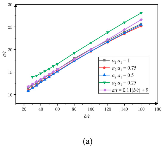
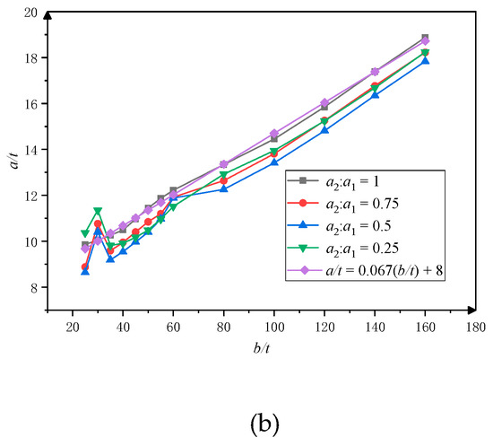
Figure 10.
Minimum edge stiffener width−thickness ratios under l/t = b/t and k = 4.26: (a) l/t = b/t; (b) k = 4.26.
As shown in Figure 10a, the constraint effects of complex edge stiffeners under a2:a1 = 1, a2:a1 = 0.75, and a2:a1 = 0.5 are obviously better than that of a2:a1 = 0.25. The constraint effect is worse and should be avoided when a2:a1 = 0.25. Therefore, it is considered that the ratio of the primary edge to the secondary edge should not be greater than 2. The relationship between a/t and b/t is linear according to l/t = b/t, and the minimum value of the edge stiffener width−thickness ratio in different proportions can be selected according to Equation (5), where a2:a1 ≥ 0.5.
According to the criterion, k = 4.26, the values of the minimum width−thickness ratio a/t are shown in Table 3 and Figure 10b.
Table 3.
Values of a/t when k = 4.26.
As can be seen from Figure 10b, the relationship between a/t and b/t is approximately linear. Equation (6) was given to obtain the minimum width−thickness ratio of complex edge stiffeners with different proportions. The statistical metrics of these two equations are shown in Table 4.
Table 4.
Statistical metrics of Equations (5) and (6).
4.3. The Applicability of the Equations
According to Table 2 and Table 3, the deformation characteristics of the flange were mainly controlled by the criterion l/t = b/t. At this time, the values of k and a/t are also larger than those when k = 4.26 is used, which has a higher safety guarantee. The criterion k = 4.26 mainly controls the bearing capacity of the element. The minimum value of a/t is smaller, and its range is more extensive. More combinations of different lengths can be carried out, and more possibilities for the section configuration can be provided.
When considering the buckling half-wavelength, the minimum value can be selected by Equation (5). When considering the buckling coefficient, the minimum value can be selected by Equation (6). To verify the applicability of the equations, Equations (5) and (6) are applied to Q235 steel with a2:a1 = 1:1, as shown in Table 5. The relative average errors of the results are 0.26% and 0.4% compared with the criterion, which are within the allowable range. Therefore, these equations can be used for different kinds of materials.
Table 5.
Values of k and l/t for Q235.
5. Optimization of Complex Edge Stiffeners by GA
The genetic algorithm (GA) is a random search method based on principles of natural evolution, in which a population of candidate solutions is evolved through special selection rules to optimize the fitness function (optimization target) during the evolution process [31]. In this paper, Python3.9.2 is used to program the section optimization program, the critical buckling stress is calculated by the FSM, and the optimal section is selected by the GA. The program flowchart is shown in Figure 11. According to the characteristics of the problem, the program contains five main files constructed with an object-oriented program: using.py provides the user data input interface and displays the output results; cufsm.py calculates the critical buckling stress of the section based on the FSM; genetics.py realizes the GA optimization design of the provided section, and optimizes the width and its proportion of the edge stiffeners; material.py contains the Material class. This module provides the Material class for the typical steel structure. Its subclasses include Q235 class, Q355 class, Q390 class, etc., which can offer a variety of steel properties and provide the function of customizing materials; section.py completes the definition of the geometric properties of the section.
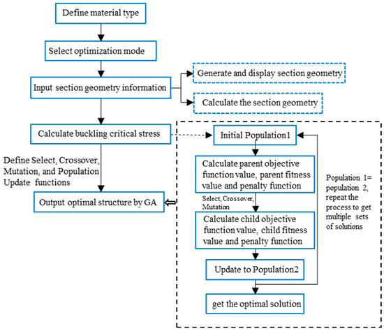
Figure 11.
Program flowchart.
As shown in Figure 9, the value of k first increases and then decreases with the increase of a/t, that is, after kmax is reached, the critical buckling stress of the edge stiffener decreases with the increase of a/t. On increasing of the edge stiffeners’ width−thickness ratio, although the edge stiffeners can continue to provide bearing capacity for the member, it also causes the waste of materials when meeting the bearing capacity requirements of the member, and buckling coefficient k represents the critical stress, which can represent the material utilization efficiency. Hence, considering economic benefits, a/t under k = kmax is the optimal width−thickness ratio for complex edge stiffeners.
Through parameterized analysis, a series of discrete points were obtained, as shown in Figure 9. The parameter kmax is the maximum value among these points, as indicated in Table 6. To obtain a more precise and advantageous optimal edge stiffener width−thickness ratio and configuration, an optimization design was conducted using the GA.
Table 6.
Values of a/t and kmax based on the FSM and GA.
Table 6 illustrates the relationship between kmax and a/t obtained through parameterized analysis and those obtained by the GA, respectively, when a2:a1 = 1. The kmax values obtained by GA are not less than those obtained by the parametric analysis. The high coefficient of determination of R2 = 0.996, the small root mean square error of RMSE = 0.006, and the small mean absolute percentage error of MAPE = 0.09% collectively indicate that the results obtained through GA are comparable to those from the parameterized analysis, without significant deviations. Therefore, the GA employed in this study is a viable and effective approach.
Through the optimization algorithm, the values of k and a/t are shown in Table 7, which are the results of the GA optimization according to the stress values under different width ratios of the primary and secondary edges. According to Table 7 and Figure 12a, when a2:a1 = 1:1, kmax is larger and the material utilization ratio is higher.
Table 7.
Values of a/t when k = kmax.
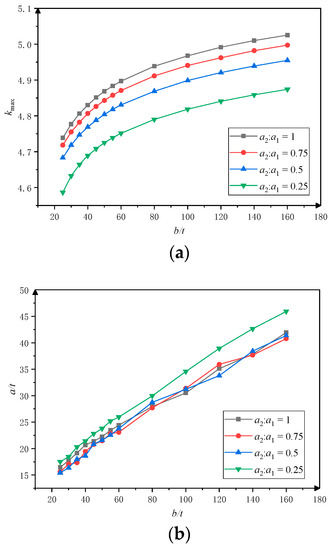
Figure 12.
Parameters for k = kmax: (a) b/t - kmax; (b) b/t - a/t.
The results of the optimal values of a/t and a2: a1 obtained by the multi-objective genetic algorithm optimization in Table 8 also prove that the material function can be better played when the width ratio of the primary and secondary edges is 1:1.
Table 8.
Optimum values of a/t and a2:a1.
Values of a/t and b/t show an approximately linear relationship, as shown in Figure 12b. Equation (7) can also be used for selection when a2:a1 ≥ 0.5. The statistical performance of this equation, for a2:a1 ratios of 1, 0.75, and 0.5, respectively, are as follows: R2 = 1.00, 0.98, 0.98; RMSE = 0.52, 1.04, 1.10; MAPE = 2.03%, 4.05%, 4.29%; and SMAPE = 2.03%, 4.05%, 4.29%.
6. Conclusions
The utilization of complex edge stiffeners has been increasingly prevalent in structural design due to their superior ability to withstand buckling. Nevertheless, there is currently a dearth of research on the sizing of edge stiffeners. In this study, we investigate the size limitations and edge stiffeners’ configurations. This study analyzes and optimizes complex edge stiffeners based on the finite strip method and relevant buckling theories. Equations are proposed to calculate the minimum edge width−thickness ratio and the optimal cross-sectional configuration for different flange width−thickness ratios. These facilitate the manufacturing of complex thin-walled members. The complex edge stiffener limit of thin-walled steel sections has been systematically studied and compared with simple edge stiffeners without considering the effect of rounded corners. The axial compression section of the thin-walled complex edge stiffener element was analyzed by changing the width−thickness ratio of the flange, the width−thickness ratio of the edge stiffener, and the width−thickness ratio of the primary and secondary edge stiffeners. The relationship between the deformation and mechanical properties of complex edge stiffener elements and the selection of edge stiffener width−thickness ratio was revealed. The method for selecting the limits of the complex edge stiffener width−thickness ratio was proposed. The main conclusions are drawn as follows:
- (1)
- According to the comparison of l/t and k values between simple and complex edge stiffeners, the advantage of simple edge stiffeners is greater when b/t is small. The advantage of complex edge stiffeners is greater when b/t is large. Under the same width−thickness ratio of the flange, the larger the width−thickness ratio of the edge stiffeners is, the more significant the advantage of complex edge stiffeners is.
- (2)
- The minimum criteria of the complex edge stiffener width−thickness ratios are given considering the deformation characteristics and the mechanical performance, that is, the half-wavelength−thickness ratio l/t = b/t and the buckling coefficient k = 4.26.
- (3)
- The table and the formula of the recommendations on the complex edge stiffener limits are given according to the criteria. The optimal value of a/t and its formula are also given, considering the economic performance.
- (4)
- Considering the material utilization efficiency, the optimal value of the complex edge stiffener width−thickness ratio a/t is given by GA. It is recommended that the width ratio of the primary and secondary edges should be 1:1.
Author Contributions
Conceptualization, J.Z. and B.L.; formal analysis, S.G. and B.L.; investigation, S.G. and H.W.; methodology, J.Z. and L.C.; supervision, J.Z. and L.C.; writing—review and editing, S.G. and L.C. All authors have read and agreed to the published version of the manuscript.
Funding
The research presented in this paper was financially supported by First-Class Project Special Funding of Yellow River Laboratory (No. YRL22IR09).
Data Availability Statement
Not applicable.
Conflicts of Interest
The authors declared that they have no conflict of interest in this work. We declare that we do not have any commercial or associative interest that represents a conflict of interest in connection with the manuscript entitled, “The Width−Thickness Ratio Limits of Thin-Walled Steel Elements with Complex Edge Stiffeners” by Junfeng Zhang, Shuran Gao, Bo Li, Liusheng Chu, Huan Wang.
References
- Leng, J.; Li, Z.; Guest, J.K.; Schafer, B.W. Shape optimization of cold-formed steel columns with fabrication and geometric end-use constraints. Thin-Walled Struct. 2014, 85, 271–290. [Google Scholar] [CrossRef]
- Xi, Y.; Jiao, S. Edge stiffeners of the cold-formed thin-walled C columns. In Proceedings of the Institute of Structural Stability and Fatigue, China Steel Construction Society Academic Exchange and Teaching Seminar (SSF-2021), Xi’an, China, 14 August 2021; pp. 30–34. (In Chinese). [Google Scholar]
- Xi, Y.; Xi, Z. The complex stiffeners for thin-walled members. Steel Constr. 2008, 23, 34–38. (In Chinese) [Google Scholar]
- Schafer, B.W.; Sarawit, A.; Peköz, T. Complex edge stiffeners for thin-walled members. J. Struct. Eng. 2006, 132, 212–226. [Google Scholar] [CrossRef]
- Winter, G. Strength of thin steel compression flanges. Trans. Am. Soc. Civ. Eng. 1947, 112, 527–554. [Google Scholar] [CrossRef]
- Desmond, T.P.; Pekoz, T.; Winter, G. Edge stiffeners for cold-formed steel members. Int. Spec. Conf. Cold-Form. Steel Struct. 1978, 1, 119–156. [Google Scholar]
- Desmond, T.P.; Pekoz, T.; Winter, G. Edge stiffeners for thin-walled members. ASCE J. Struct. Div. 1981, 107, 329–353. [Google Scholar] [CrossRef]
- Schafer, B.W. Cold-Formed Steel Behavior and Design: Analytical and Numerical Modeling of Elements and Members with Longitudinal Stiffeners; Cornell University: Ithaca, NY, USA, 1997. [Google Scholar]
- Schafer, B.W.; Peköz, T. Laterally braced cold-formed steel flexural members with edge stiffened flanges. J. Struct. Eng. 1999, 125, 118–127. [Google Scholar] [CrossRef]
- Sarawit, A.T.; Peköz, T. A design approach for complex stiffeners. In Proceedings of the International Specialty Conference on Cold-Formed Steel Structures: Recent Research and Developments in Cold-Formed Steel Design and Construction, St. Louis, MI, USA, 10–20 October 2000; pp. 1–12. [Google Scholar]
- Bambach, M.R. Design of uniformly compressed edge-stiffened flanges and sections that contain them. Thin-Walled Struct. 2009, 47, 277–294. [Google Scholar] [CrossRef]
- Bambach, M.R. Experiments of edge-stiffened plates in uniform compression. Thin-Walled Struct. 2011, 49, 343–350. [Google Scholar] [CrossRef]
- Huang, L.; Yang, W.; Shi, T.; Qu, J. Local and distortional interaction buckling of cold-formed thin-walled high strength lipped channel columns. Int. J. Steel Struct. 2021, 21, 244–259. [Google Scholar] [CrossRef]
- Guo, Y.; Yao, X. Distortional buckling behavior and design method of cold-formed steel lipped channel with rectangular holes under axial compression. Math. Biosci. Eng. 2021, 18, 6239–6261. [Google Scholar] [CrossRef]
- Ye, W.; Zhao, W.; Li, F.; Zhu, Y. Optimization on lip angle of cold-formed thin-walled Z-section. J. Ningbo Univ. 2018, 13, 65–69. (In Chinese) [Google Scholar]
- Seah, L.K.; Rhodes, J. Simplified buckling analysis of plate with compound edge stiffeners. J. Eng. Mech. 1993, 119, 19–38. [Google Scholar] [CrossRef]
- Du, F.; Xi, Y. Research on for cold-formed steel channel columns with complex edge stiffeners. In Proceedings of the Institute of Structural Stability and Fatigue, China Steel Construction Society Academic Exchange and Teaching Seminar (ASSF-2010), Ningbo, China, 8 August 2010; pp. 296–302. (In Chinese). [Google Scholar]
- Jiao, S.; Xi, Y. Research on edge stiffeners for cold-formed channel columns under axial load. Steel Constr. 2011, 26, 13–16. (In Chinese) [Google Scholar]
- Zhang, J.; Li, B.; Li, A.; Pang, S. Critical stress determination of local and distortional buckling of lipped angle columns under axial compression. Buildings 2022, 12, 712. [Google Scholar] [CrossRef]
- Zhang, J.; Feng, M.; Deng, E.; Pang, S. Numerical investigation and design of cold-formed steel angle columns with complex edges under axial compression. KSCE J. Civ. Eng. 2023, 27, 630–642. [Google Scholar] [CrossRef]
- Aruna, G.; Roy, K.; Lim, J.B.P.; Suresh Kumar, P. Cold-formed steel equal angles with complex edge stiffeners under axial-compression laboratory testing, numerical simulation, and design. Pract. Period. Struct. Des. Constr. 2022, 27, 04022012. [Google Scholar] [CrossRef]
- Wang, C.G.; Zhang, Z.N.; Zhang, Y.C. Experimental investigation on channel columns with complex edge stiffeners and intermediate stiffeners under axial compression. Eng. Mech. 2013, 30, 221–228+254. (In Chinese) [Google Scholar] [CrossRef]
- Song, B.; Wang, L.G.; Wang, C.G. Stability behavior of channel columns with complex edge stiffeners and cap shaped stiffeners. J. Northeast. Univ. 2018, 39, 143–147. (In Chinese) [Google Scholar] [CrossRef]
- Song, B.; Wang, L.G.; Wang, C.G. Experimental investigation on channel columns with complex edge stiffeners and cap Shaped Stiffeners under eccentric compression. J. Northeast. Univ. 2018, 39, 272–277. (In Chinese) [Google Scholar] [CrossRef]
- AISI S100-16; North American Specification for the Design of Cold-Formed Steel Structural Members. American Iron and Steel Institute: Washington, DC, USA, 2016.
- AS/NZS 4600:2018; Cold-Formed Steel Structures. Standards Australia/Standards New Zealand. Australian/New Zealand Standard: Sydney, Australia, 2018.
- GB 50018-2020; Technical Specification for Cold-Formed Thin-Walled Steel Structures. China Planning Publishing House: Beijing, China, 2020. (In Chinese)
- Li, Z.; Batista Abreu, J.C.; Leng, J.; Ádány, S.; Schafer, B.W. Review: Constrained finite strip method developments and applications in cold-formed steel design. Thin-Walled Struct. 2014, 81, 2–18. [Google Scholar] [CrossRef]
- EN 1993-1-3; Eurocode 3—Design of Steel Structures—Part 1-3: General Rules—Supplementary Rules for Cold-Formed Members and Sheeting. European Committee for Standardization: Brussels, Belgium, 2006.
- Gonçalves, R.; Martins, A.D.; Camotim, D. Elastic bifurcation, postbuckling behavior, and collapse of thin-walled regular polygonal columns. J. Eng. Mech. 2023, 149, 04022090. [Google Scholar] [CrossRef]
- Parastesh, H.; Hajirasouliha, I.; Taji, H.; Bagheri Sabbagh, A. Shape optimization of cold-formed steel beam-columns with practical and manufacturing constraints. J. Constr. Steel Res. 2019, 155, 249–259. [Google Scholar] [CrossRef]
Disclaimer/Publisher’s Note: The statements, opinions and data contained in all publications are solely those of the individual author(s) and contributor(s) and not of MDPI and/or the editor(s). MDPI and/or the editor(s) disclaim responsibility for any injury to people or property resulting from any ideas, methods, instructions or products referred to in the content. |
© 2023 by the authors. Licensee MDPI, Basel, Switzerland. This article is an open access article distributed under the terms and conditions of the Creative Commons Attribution (CC BY) license (https://creativecommons.org/licenses/by/4.0/).