Abstract
Space truss structures are commonly used in long-span roof structures. Recently, middle-hung scoreboards (MHS), a kind of large-scale display device flexibly suspended in the center of the roof, have been widely used in gymnasiums. However, the effect of the MHS on dynamic characteristics and earthquake response of space truss structures needs to be investigated. In this paper, the effect on the MHS under horizontal earthquake motion is studied. The simplified model, where the MHS is simplified to four fixed masses on a structure, and the flexibly suspended model are established with Abaqus software, and the earthquake response is analyzed by the time-history method with the dynamic explicit method. The influence laws of the wire extent and the MHS weight are discussed. Compared with the simplified model, the nodal acceleration and the axial force rise up to 2.123 times and 1.575 times, respectively, in the flexibly suspended model, indicating that the amplification effect of the MHS acts significantly under horizontal earthquake motion. It turns out that the earthquake response of a space truss structure could be underestimated if a simplified model is used. The crest acceleration of both top chord nodes and bottom chords nodes are greatly influenced by the MHS weight but little affected by the wire extent. The influence laws of the MHS weight and the wire extent on crest axial forces of structural members are very complicated. The central regions of both the top chords and the bottom chords are the most affected regions, and the boundary regions parallel to the direction of the earthquake motion are the least affected regions. It is suggested that the envelope value under the conditions of different wire extent and MHS weight are used for structural design.
1. Introduction
With the characteristics of reasonable force, diverse shapes and large span [1], space truss structures are widely used in long-span public buildings, such as stadiums and terminal buildings. Such buildings are usually symbolic of urban culture and are densely populated sites, and special attention should be paid to earthquake resistance. The space truss structure itself has good earthquake performance, but the concrete layout and design of the structure system still need to be improved. Hence, the earthquake performance of the space truss structure has become one of the hot research topics in the field of building structures.
In recent years, researchers around the world have conducted much research on the earthquake performance of long-span space structures. Zhang et al. [2] conducted a shaking table test on the scale model of a long-span steel structure, and the results showed that the structure responded the most under a three-way earthquake. Takiuchi et al. [3] pointed out that the selection of a grid frame has an important influence on the earthquake performance of the roof frame. At the same time, the importance of pseudo-earthquake energy is discussed based on the double mode method, and the concept of equivalent earthquake load of reticulated shell roof is proposed. F. Coadron et al. [4] paid special attention to the response modes of the internal components of five typical large-span spatial structures under horizontal and vertical earthquake excitation. The applicability of the incremental dynamic analysis method to the earthquake research of long-span space structures is verified. Li et al. [5] found that the uncoordinated displacement of the lower support structure has an important influence on the earthquake damage of the grid structure. A. Oghaddam [6] showed that the dome structure would have a large displacement under the impact load and the internal forces in the joints and rods caused by strong earthquakes would even exceed the gravity load of the structure itself. Gu et al. [7] pointed out that the spatial effect of the ground motion should be considered when the long-span grid is affected by vertical earthquake action. According to the study of Wei et al. [8], the dynamic failure of long-span space grid structure includes strength failure and instability failure. Vatansever [9] pointed out that the uneven settlement would cause the accumulation of internal forces in the components of the long-span space structure, which would lead to the buckling of the rods and then make the whole structure face the risk of continuous collapse. Kato et al. [10] verified the effectiveness of constraint and support methods in improving the earthquake capacity of large-span space structures. Thai et al. [11] analyzed the linear and nonlinear responses of structures with trusses applied under earthquakes by using the Newmark method and the Newton–Raphson method. In summary, the current seismic response analysis methods of grid structures include not only the modal decomposition response spectrum method and time history method but also include the incremental dynamic method, static nappe method [12] and two-stage nappe method [13]. Nettis et al. [14] studied the applicability and effectiveness of a truss structure applied to bridges based on displacement assessment and nonlinear static method and proposed an effective method to evaluate the earthquake performance evaluation and vulnerability analysis of bridges with truss structures. Chen et al. [15] studied the structural characteristics of long-span truss bridges subjected to earthquakes and proposed an effective reinforcement method. Cui et al. [16] proposed the initial shear mechanism and the calculation method of the ultimate shear strength of the joints by studying the internal force response generated when the joints of the roof of a long-span spatial structure resisted earthquakes and strong shear forces. At present, the factors such as the ratio of height to span, the form of support and the multi-dimensional earthquake action of earthquake waves have been studied in the earthquake response analysis.
The roof of a stadium usually is hung a variety of equipment, among which the middle-hung scoreboard (MHS), as shown in Figure 1, has become one of the important indicators for evaluating whether a stadium is modern enough. With the development of sports events and recreational activities, the number of applications has increased rapidly. In order to pursue a better display effect, the MHS has developed in the direction of a large display area and small pixel spacing, and its weight increases accordingly [17], forming a larger hanging device in the center of the roof. Interaction between the MHS and the roof structure is obvious, whether under static or earthquake action, forming an MHS-roof coupling system. There are significant differences in the self-vibration characteristics between the coupled system and the pure roof structure. There are few studies considering the effect of the MHS on the dynamic characteristics and earthquake response of space truss structures in currently published references, and the theoretical research on the interaction between the two is insufficient. The influence law of flexible hanging MHS on the earthquake response of space truss structures needs to be further revealed.
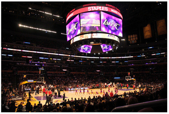
Figure 1.
The scoreboard construction site in a gymnasium.
Starting from the horizontal earthquake action, this paper analyzes the influence law of the wire extent and MHS weight on acceleration and axial force response on the coupling system by comparing the response under the condition that the suspension MHS and MHS are simplified as four fixed masses on the structure. This paper aims to explore the influence law of flexible hanging MHSes on the earthquake response of space truss structures under unidirectional horizontal earthquake action and the interaction mechanism of the two. It is of reference value to the design and analysis of stadium roof structures with an MHS installed or retrofitted.
2. Analysis Models and Methods
2.1. FE Model
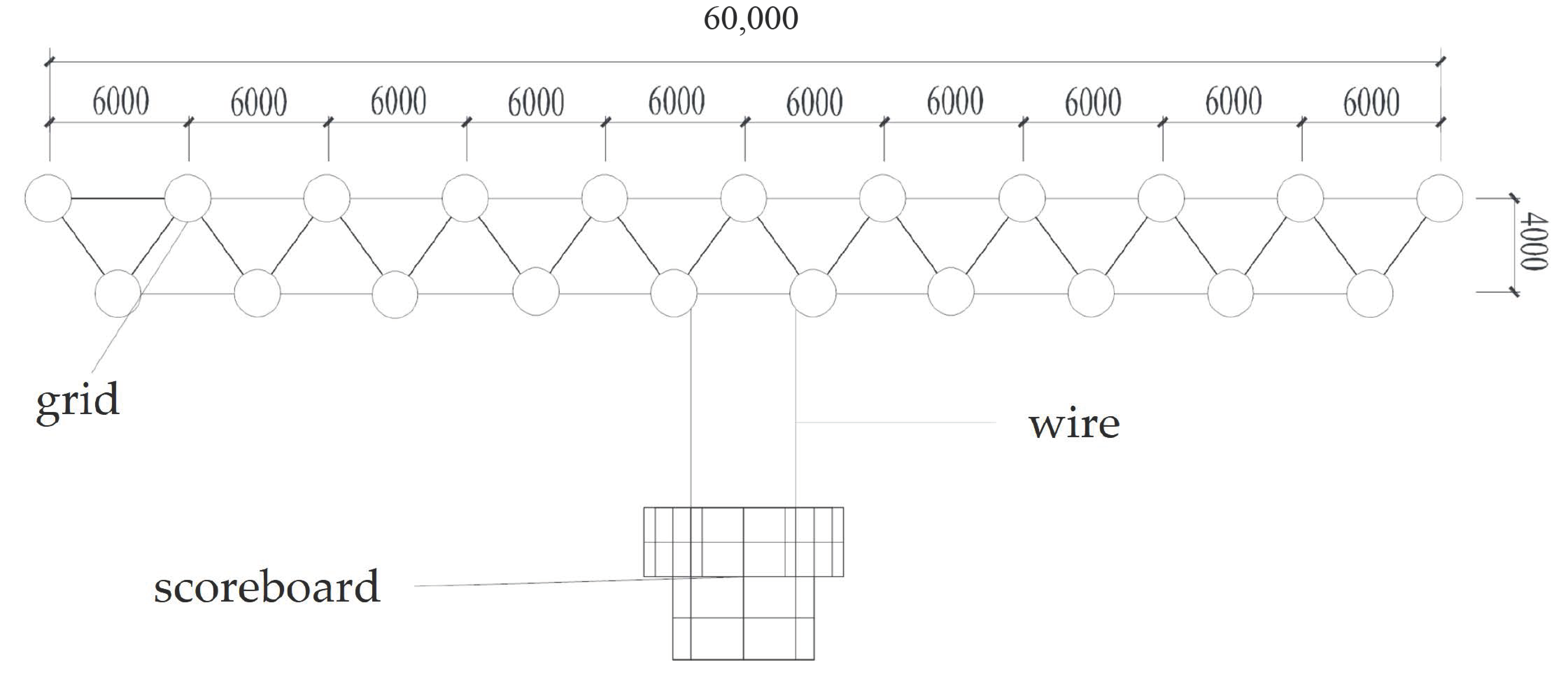
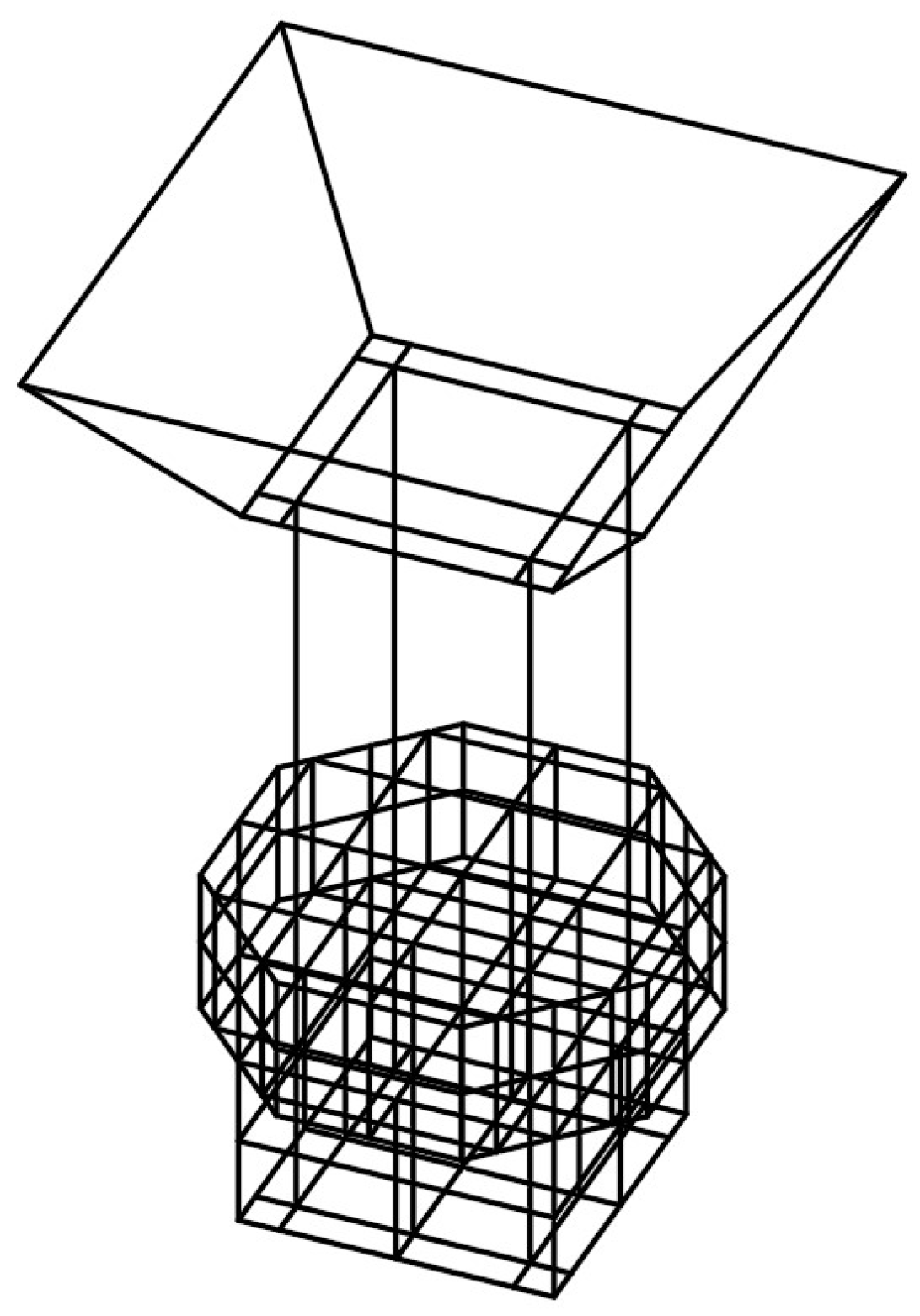
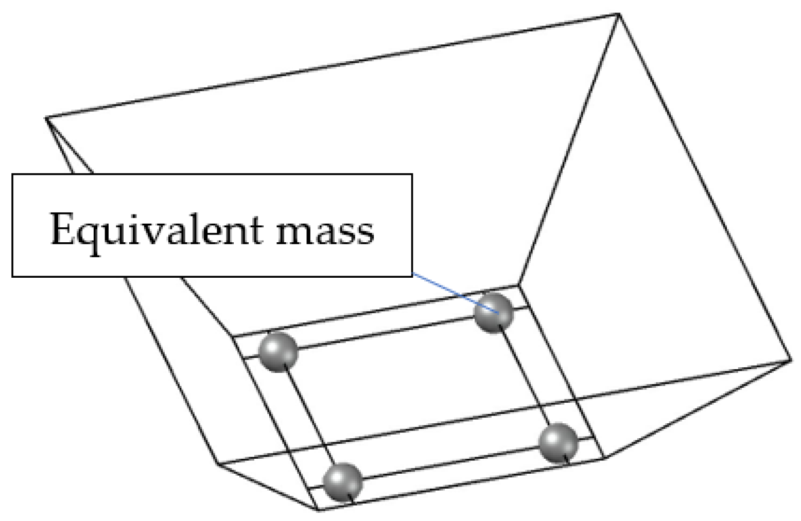
A space truss structure of a gymnasium is taken as the analysis model. The boundary of the space truss is square, and the span is 60 m; the height of the space truss is 4 m (shown in Figure 2), and the spacing of the top chords and bottom chords is 6 m (shown in Figure 3). A platform for supporting the middle-hung scoreboard (MHS) is located in the center of the bottom layer of the space truss structure, and it is made of additional crossing beams G3, as shown in Figure 3. The MHS is suspended on the crossing nodes on the platform by four wires. MHS has a maximum width of 8.6 m and a total height of 6.5 m. The wire extent can be adjusted by using a hoist system. The section of space truss members is a circular pipe. The section specifications of the structural members are shown in Table 1, and the sections of different structural members are displayed in Figure 2 and Figure 3. Space truss members and platform members are made of Q355B steel, whose elasticity modulus is 2.06 × 10⁵ N/mm2, and characteristic yield strength is 355 N/mm2, and the wires are made of spiral strands, whose elasticity modulus is 1.65 × 10⁵ N/mm2, and ultimate tensile strength is 1670 N/mm2. The FE model is built in Abaqus software. When the flexibly suspended model is used, the MHS is directly connected to the pound-shaped load-bearing platform by four wires, which were set up as truss elements in the software, as shown in Figure 4. In this case, the MHS and the roof structure will interact with each other during the earthquake, forming a new coupling structure. Exploring the earthquake response characteristics of coupling structures is one of the main tasks of this paper. When the simplified model is adopted, the mass of the MHS will be equivalent to the weight of four equal energy sizes applied to the four lifting points of the load-bearing platform, as shown in Figure 5. The earthquake response difference between the flexibly suspended model and the simplified model is the focus of this paper. The truss element is used for space truss members and wires, and the beam element is used for platform members.
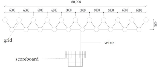
Figure 2.
Distribution of the space truss structure with an MHS, front view/mm.
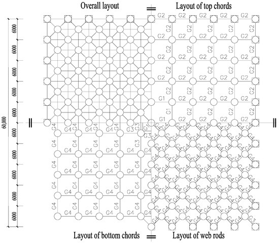
Figure 3.
Distribution of the space truss structure with an MHS, top view/mm.

Table 1.
Section specifications of structural members.
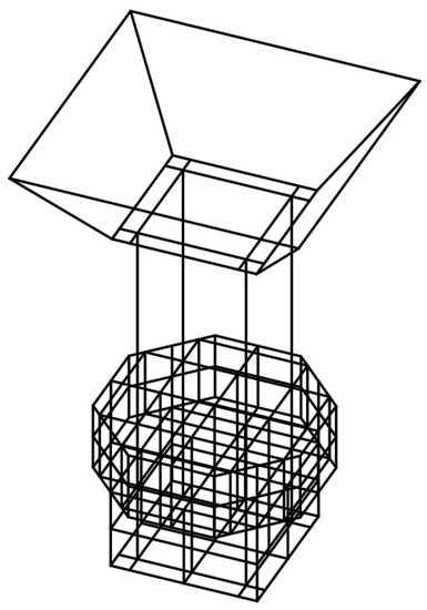
Figure 4.
The flexibly suspended model.

Figure 5.
The simplified model.
Similar to the mass pendulum, the wire extent and the MHS weight are the main parameters affecting the dynamic characteristics of the MHS. Different wire extents and different weights are selected to study the influence of the MHS on the earthquake response of the space truss structure. In practice, a safe distance of about 1 m is kept between the MHS and the platform, and a wire extent is selected for every 0.5 m interval between 1 m and 9 m. If the extent of the wire is 0 m, it means that the MHS is simplified as the fixed masses on the suspension nodes to make a simplified model. Applications of the MHS in recent years are mostly more than 20 t, and the heaviest surpasses 50 t, and weights range from 20 t to 60 t at an interval of 5 t. The standard value of a dead load (D) includes the standard value of the uniformly distributed dead load of the roof is taken as 1.0 kN/m2 and the weight of the structure. The standard value of the uniform live load of the roof is taken as 0.5 kN/m2, and the representative value of gravitational force is taken as 1.0 D + 0.5 L. The support setting conditions are assumed to be a three-way fixed hinge support, as shown in Figure 3.
2.2. Analysis Method
Commonly used earthquake response analysis methods for space structures with trusses include the mode decomposition response spectrum method, the time–history method and the simplified method [18]. Common integration algorithms are divided into explicit algorithms and implicit algorithms.
Since the wires are the only tension elements, the integrated model composed of a space structure with trusses and an MHS is the mechanism. Therefore, the time–history method with a dynamic explicit algorithm is used for the earthquake response of a space truss structure with an MHS. The Abaqus software is employed for the analysis, and the rationality of the analysis method for a long-span roof structure with an MHS has been verified by a shaking table test on a 94 m structure with suspen-dome [19,20].
2.3. Earthquake Motions
According to the code GB50011 2010 [21], when adopting a time–history analysis method, more than three earthquake records should be chosen according to the categories of construction sites and design earthquake groups, and the artificial earthquake records should not be less than two-thirds of the total records. The number of time-history records of earthquake should be properly defined so that the seismic input of time-history method can be consistent with the mode decomposition response method in a statical sense. When three groups of acceleration time–history bight are inputted, the calculated results are appropriate to the envelope value of the time–history method.
Three parts of the ground motion should be fully considered when selecting earthquake waves, including ground motion intensity, spectrum characteristics and ground motion duration. The intensity of the ground motion is generally the highest value of acceleration. Amplitude modulation is conducted according to the crest of acceleration corresponding to the corresponding fortification intensity, and the crest of the acceleration is adjusted according to the equation fortification intensity, which refers to the earthquake intensity approved as the basis for earthquake fortification in an area according to the authority prescribed by the state.
where and are adjusted earthquake acceleration curves and crest values, and and are the original recorded earthquake acceleration curves and crests.
In this paper, the design site condition is Class II; the design earthquake group is the second group; the earthquake fortification intensity is 8 degrees; and the basic design acceleration is 0.2 g. Accordingly, the selected acceleration records are the natural earthquake waves El-Centro and Taft, and the artificial wave is RH4TG040. Figure 6 shows that the earthquake response spectrum after amplitude modulation is in good agreement with the designed response spectrum.
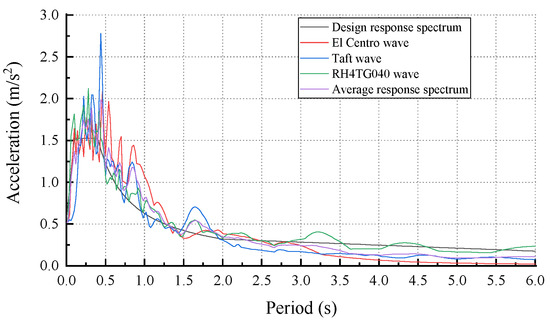
Figure 6.
Response spectrum curves.
Although the spatial effect of the earthquake response on the space truss structure is significant, the study of the response under unidirectional earthquake action in the basic research stage is helpful in revealing the interaction mechanism between the MHS and the space truss structure. In this paper, only the structural response under horizontal earthquake waves is studied. In future studies, the influence of earthquake wave direction on the structural response will be further explored. In addition, the span of this example is 60 m, and the traveling wave effect is not significant. Therefore, the ground motion input methods adopted are one-dimensional horizontal input and multi-point consistent input, and the effects of other input methods on the earthquake response of the space truss with an MHS will be studied in the future.
3. Results and Analysis
The dynamic characteristics, including the natural vibration frequency and vibration mode shapes, are obtained. The earthquake response, including the nodes’ acceleration and the internal force of both the simplified model and the flexibly suspended model under different MHS weights and wire extents, are obtained. The earthquake response is compared and analyzed between the two kinds of models, and the effect of the MHS weight and the wire extent on the dynamic characteristics and earthquake response are discussed.
3.1. Nodes’ Acceleration
According to the code GB50011 2010, the envelope value of the crest value of the horizontal acceleration response of the node under the excitation of the three groups of earthquake waves is taken as the crest value for the structural design. The crest acceleration of node I under the condition that the MHS weight is w and the wire extent is l is set as , where i is a positive integer. According to Equation (2), the crest change rate of acceleration of the i th node, , can be obtained. in Equation (2) represents the crest acceleration of node i under the condition that the MHS weight is w, and the MHS is simplified to fixed masses on suspension nodes, the simplified model.
According to Equation (3), the maximum rate of of a group of nodes can be computed to analyze the overall effect of the MHS weight and wire extent, where n is the number of a node group. Nodes of the space truss structure are separated into two groups, the nodes of top chords and the nodes of bottom chords.
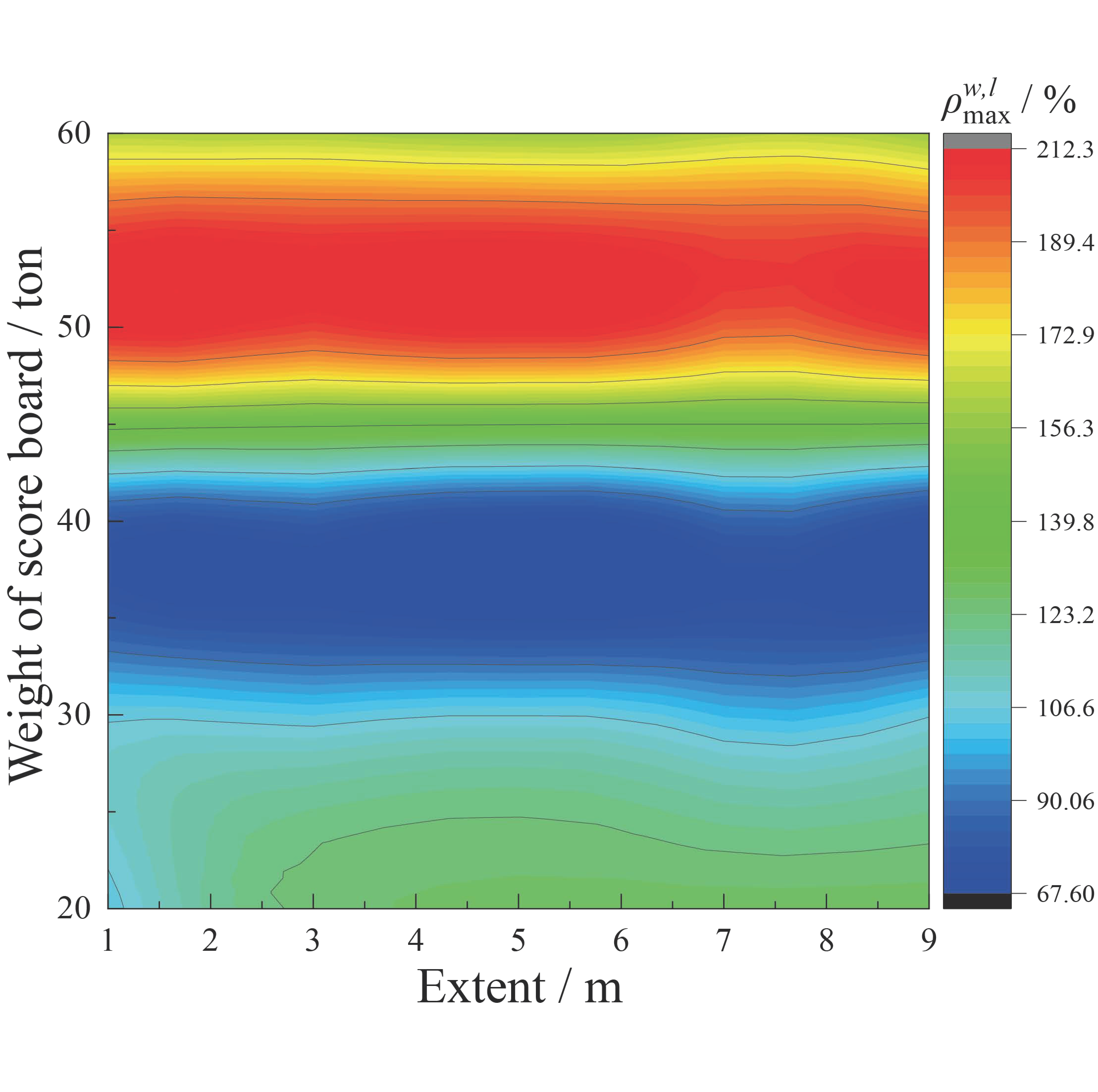
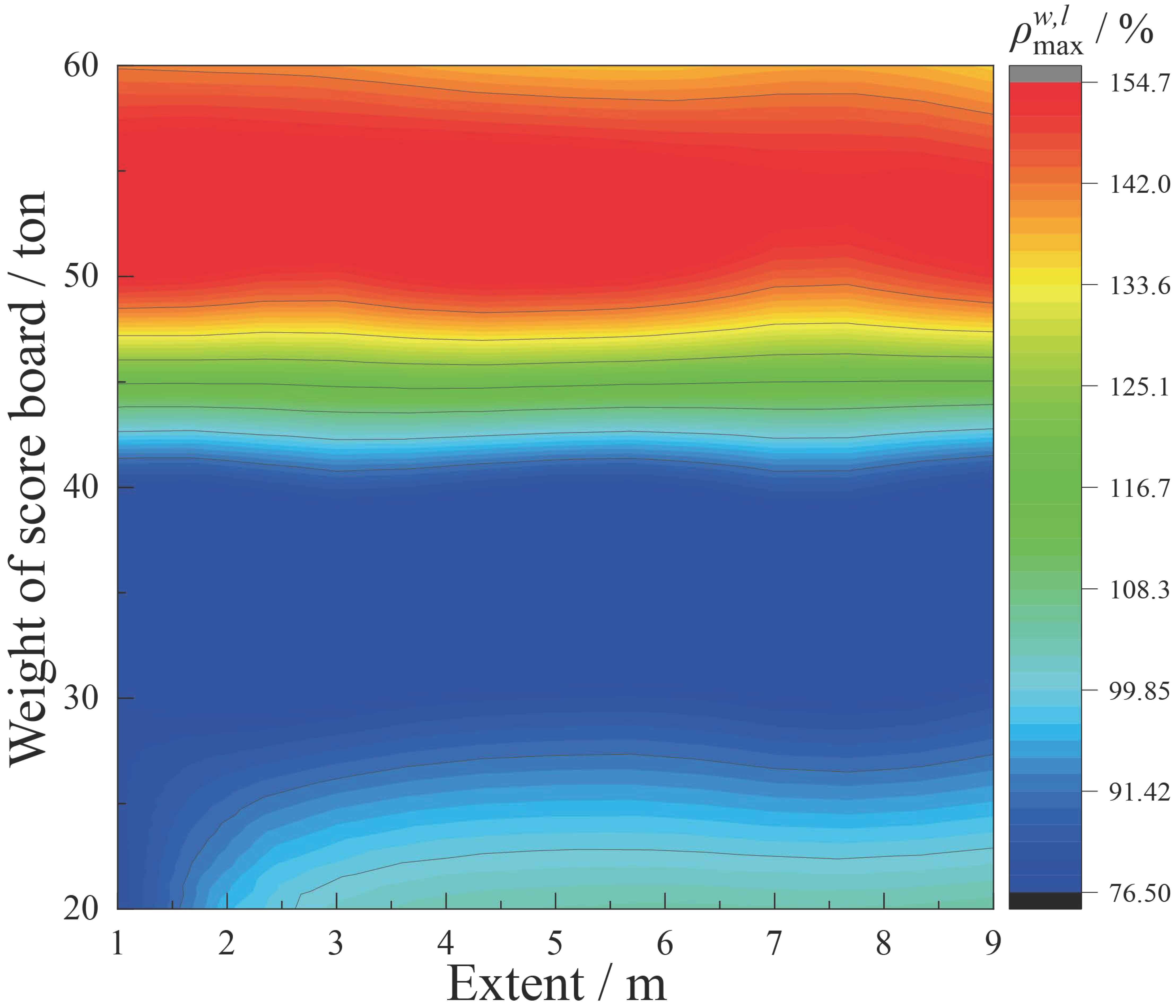
Figure 7 and Figure 8 show the contours of values of the top chord nodes and the bottom chord nodes, respectively, with the change of the wire extent and the MHS weight. Figure 7 shows that the values of the top chord nodes are between 67.6% and 212.3%. Compared with the simplified model, the acceleration of the top chord nodes rises up to 2.123 times in the flexibly suspended model, indicating that the amplification effect of the MHS significantly influences the acceleration of the top chord nodes. On the whole, the value of the top chord nodes is little affected by the wire extent. With the increase of the MHS weight, the values of the top chord nodes decrease first, reach a minimum value when the weight is 35 t, and then increase 212.3% when the MHS weight is between 50 t and 55 t. Figure 8 shows that the values of the bottom chord nodes are between 76.5% and 154.7%. Compared with the simplified model, the acceleration of the bottom chord nodes could increase up to 1.5 times under the condition of a flexibly suspended MHS. Results in both Figure 7 and Figure 8 indicate that nodal acceleration results of the space truss structure in the flexibly suspended model are significantly larger than those in the simplified model under the horizontal earthquake motion. It turns out that nodal acceleration results could be underestimated if a simplified model is used. Figure 8 also demonstrates that the values of the bottom chord nodes are greatly influenced by the MHS weight but little affected by the wire extent. With the increase of the MHS weight, the values decrease first and then increase. When the MHS weight is between 50 t and 60 t, the values of the bottom chord nodes are basically maintained at the highest level. In all, the nodal acceleration results of the space truss structure in the flexibly suspended model are greatly influenced by the MHS weight but little affected by the wire extent under the horizontal earthquake motion.

Figure 7.
value contour map of top chord node.
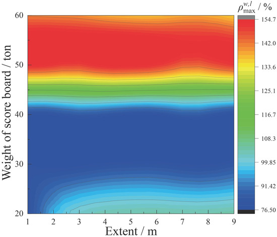
Figure 8.
value contour map of bottom chord node.
Figure 7 and Figure 8 show only the values, but the most affected nodes of the space truss cannot be obtained. In order to display the change rate of different nodes, contours of the top chord nodes and the bottom chord nodes under different MHS weights and different wire extents are shown in Table 2. It is shown that in the flexibly suspended model, the central regions of both the top chord and the bottom chord are the most affected regions, and the boundary regions parallel to the direction of the earthquake motion are the least affected regions. It also shows that the most affected regions and the least affected regions are not influenced by the MHS weight and the wire extent. The deep cause is that the MHS is suspended in the center of the structure, and the swing effect of the MHS acts directly on the central part of the space truss. Hence, the central part of the space structure with the truss should be concerned if a simplified model is used for structural design.
Table 2.
Contours of crest acceleration change rate of top chord and bottom chord nodes.
3.2. Axial Forces
The envelope value of the crest axial forces of a structural member under the excitation of three earthquake waves is taken as the crest axial force response of the structural member. The crest value of the axial force response of the structural member j is set as under the condition that the MHS weight is w and the wire extent is l. The change rate of the crest axial force of the member j, is set as as shown in Equation (4), where represents the crest axial force of the structural member j under the condition that the score board mass is w, and the score board is simplified to a fixed mass on suspension nodes of the support platform (the simplified model). Equation (5) can calculate the maximum change rate of the crest axial forces of the specific part of the space structure. Parameter p represents the total number of structural members in the part.
Figure 9, Figure 10 and Figure 11 show the contours of values of top chords, web rods and bottom chords, respectively, with the change of wire extent and MHS weight. Figure 7 shows that the values of the top chords are between 34% and 157.5%. Considering the Equation (4), it indicates that compared with the simplified model, the crest thrust force of some top chords in the flexibly suspended model can increase up to 1.575 times. Figure 10 displays that the values of the web rods are between 45.6% and 102.2%. It indicates that compared with the simplified model, the crest axial force of some web rods in the flexibly suspended model can increase up to 1.022 times. Figure 11 shows that the values of the bottom chords are between −41.8% and 38.8%. It indicates that compared with the simplified model, the crest axial force of some bottom chords in the flexibly suspended model can increase up to 0.388 times. It turns out that axial forces of space truss members could be underestimated if a simplified model is used instead of a flexibly suspended model.

Figure 9.
value contour of top chords.
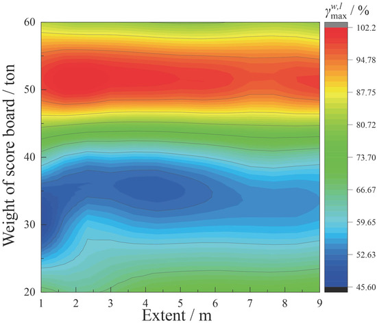
Figure 10.
value contour of web rods.

Figure 11.
value contour of bottom chords.
Figure 9 shows that influence laws of the MHS weight and the wire extent on the value of top chords are complicated. The maximum value occurs when the MHS weight is 60 t, and the wire extent is 4 m. The minimum value occurs when the MHS weight is 30 t, and the wire extent is 1 m. Figure 10 shows that the value of web rods is mainly influenced by the MHS weight but little affected by the wire extent. The maximum value occurs when the MHS weight is 50 t, and the wire extent is 2 m. The minimum value occurs when the MHS weight is 30 t, and the wire extent is 1 m. Figure 11 shows that influence laws of the MHS weight and the wire extent on the value of bottom chords are complicated. The minimum value occurs when the MHS weight is 30 t, and the wire extent is 1 m. When the MHS weight is greater than 40 t, the value is less affected by the wire extent.
The contours of the values of the top chords, web rods and the bottom chords are listed in Table 3. In general, the values of the top chords near the boundaries, especially the value of the top chords perpendicular to the earthquake input direction, are larger than those of other top chords. The distribution of the values of web rods is complex, but the value of most web rods is maintained at a low standard. The values of the bottom chords are maintained at a low standard and distributed evenly on the whole, and the values of the middle support platform are especially small. In addition, when the MHS weight is 30 t, and the extent of the wire is 1 m, the values of most structural members are significantly less than those in other cases.
Table 3.
Contours of crest axial force change rate of top chords, web rods and bottom chords.
4. Conclusions
Middle-hung scoreboards are widely used in gymnasiums. However, the effect of the MHS on earthquake response of space truss structures needs to be investigated. The effect of the MHS under horizontal earthquake motion is studied. The simplified model and the flexibly suspended model are established with Abaqus software, and the earthquake response is analyzed with a time–history method with a dynamic explicit method. The influence of the wire extent and the MHS weight are discussed.
Compared with the simplified model, the nodal acceleration and the axial force rise up to 2.123 times and 1.575 times, respectively, in the flexibly suspended model, indicating that the amplification effect of the MHS is significant under horizontal earthquake motion. It turns out that earthquake response of space truss structures could be underestimated if a simplified model is used.
The MHS weight and the wire extent significantly influence earthquake response. The crest acceleration of both top chord nodes and bottom chords nodes are greatly influenced by the MHS weight but little affected by the wire extent. The influence laws of the MHS weight and the wire extent on crest axial forces of structural members are very complicated.
In the flexibly suspended model, the central regions of both the top chord and the bottom chord are the most affected regions, and the boundary regions parallel to the direction of the earthquake motion are the least affected regions. It also shows that the most affected regions and the least affected regions are not influenced by the MHS weight and wire extent. Hence, the central part of the space structure with trusses should be concerned if a simplified model is used for structural design.
Author Contributions
Conceptualization, R.L. and C.W.; methodology, T.C.; software, T.C.; validation, P.W.; Dynamic analysis, P.W.; investigation, T.C.; writing—original draft preparation, R.L.; writing—review and editing, G.W.; visualization, P.W.; supervision, G.W.; project administration, R.L.; funding acquisition, R.L. All authors have read and agreed to the published version of the manuscript.
Funding
This research was funded by [the Natural Science Foundation of Shandong] grant number [ZR201911030049].
Institutional Review Board Statement
Not applicable.
Informed Consent Statement
Not applicable.
Data Availability Statement
All data is presented in the paper. There is no more data for readers.
Conflicts of Interest
The authors declare no conflict of interest.
References
- Li, X.J. Rerearch on Conceptual Design of Gymnasium Structure; Beijing University of Technology: Beijing, China, 2005. [Google Scholar]
- Zhang, A.L.; Wang, X.Q.; Liu, X.C. Shaking table test on overall-scale model of long-span steel structure of Beijing Daxing International Airport terminal. J. Build. Struct. 2021, 42, 1–13. [Google Scholar] [CrossRef]
- Takiuchi, Y.; Kato, S.; Nakazawa, S.; Higashiyama, Y. Statically equivalent earthquake loads based on two-mode-based approach for single layer reticulatedshells. Eng. Struct. 2022, 260, 114242. [Google Scholar] [CrossRef]
- Cedron, F.; Elghazouli, A.Y. Seismic performance of single layer steel cylindrical lattice shells. J. Constr. Steel Res. 2019, 163, 105772. [Google Scholar] [CrossRef]
- Li, J.C.; Qu, Z.; Wang, T. Lessons from the earthquake behavior of a steel grid roof structure heavily damaged in Lushan earthquake. Earthq. Eng. Eng. Vib. 2019, 18, 95–111. [Google Scholar] [CrossRef]
- Moghaddam, H.A. Seismic behaviour of space structures. In Proceedings of the 13th World Conference on Earthquake Engineering, Vancouver, BC, Canada, 1–6 August 2004; p. 523. [Google Scholar]
- Gu, Z.Y.; Liu, W.Q.; Wang, S.G.; Du, D.S. Earthquake response analysis of long-span truss structures under multi-support excitations. J. Nanjing Tech Univ. Nat. Sci. Ed. 2017, 39, 75–84. [Google Scholar] [CrossRef]
- Wei, J.P.; Tian, L.M.; Hao, J.P. Improving the progressive collapse resistance of long-span single-layer spatial grid structures. Constr. Build. Mater. 2018, 171, 96–108. [Google Scholar] [CrossRef]
- Cüneyt, V. Investigation of buckled truss bars of a space truss roof system. Eng. Fail. Anal. 2019, 106, 104–156. [Google Scholar] [CrossRef]
- Kato, S.; Takiuchi, Y.; Abe, K.; Mukaiyama, Y.; Nakazawa, S. Effectiveness of buckling restrained braces for upgrading earthquake resistant capacity of single layer grid dome. Engstruct 2022, 261, 114280. [Google Scholar] [CrossRef]
- Huu-Tai, T. Nonlinear inelastic time-history analysis of truss structures. J. Constr. Steel Res. 2011, 67, 1966–1972. [Google Scholar] [CrossRef]
- Luo, Y.F.; Xiang, Y.; Shen, Z.Y. Research and application status of earthquake analysis techniques for large-span spatial structures. Chin. Q. Mech. 2015, 36, 1–10. [Google Scholar] [CrossRef]
- Qu, Y.; Liu, S.D.; Cheng, J.J.; Luo, Y.F.; Ma, H.Z.; Wang, W.J. Two-stage pushover analysis procedure for earthquake evaluation of spatial structures under multidimensional earthquake. J. Build. Struct. 2022, 43, 17–25. [Google Scholar]
- Andrea, N.; Pietro, I.; Domenico, R.; Giuseppina, U.; Jose, M.A. Displacement-based earthquake performance assessment of multi-span steel truss bridges. Eng. Struct. 2022, 254, 113832. [Google Scholar] [CrossRef]
- Chen, X.; Li, H.; Agrawal, A.K.; Ettouney, M.; Wang, H. Performance-based retrofits of long-span truss bridges based on the alternate load path redundancy analysis. J. Bridge Eng. 2022, 28, 04022141. [Google Scholar] [CrossRef]
- Cui, Y.; Yang, X.Y.; Liu, H.T.; Satoshi, Y. Earthquake behavior of steel space truss connections to reinforced concrete supporting columns. Adv. Struct. Eng. 2022, 25, 136943322110623. [Google Scholar] [CrossRef]
- Hao, W.Z.; Wang, J.Q.; Li, Q. Introduction to the center-hung display scheme of a provincial gymnasium. Video Eng. 2019, 43, 23–25+45. [Google Scholar] [CrossRef]
- JGJ 7–2010[S]; Technical Specihcation for Space Frame Structures. China Architecture & Building Press: Beijing, China, 2010.
- Xue, S.; Zhao, Z.; Li, X.; Liu, R.; Dezhkam, M.; Lu, Z.; Liu, T.; Fan, Q.; Jing, H. Shaking Table Test Research on the Influence of Center-Hung Scoreboard on Natural Vibration Characteristics and Seismic Response of Suspen-Dome Structures. Buildings 2022, 12, 1231. [Google Scholar] [CrossRef]
- Xue, S.; Lu, Z.; Li, X.; Liu, R.; Zhao, Z.; Jing, H.; Fan, Q.; Liu, T.; Dezhkam, M. Experimental and numerical investigations on the influence of center-hung scoreboard on dynamic characteristics of suspend-dome structure. J. Build. Eng. 2022, 57. [Google Scholar] [CrossRef]
- GB50011-2010; Code for Earthquake Design of Buildings. 2016 ed.; China Architecture & Building Press: Beijing, China, 2010.


Disclaimer/Publisher’s Note: The statements, opinions and data contained in all publications are solely those of the individual author(s) and contributor(s) and not of MDPI and/or the editor(s). MDPI and/or the editor(s) disclaim responsibility for any injury to people or property resulting from any ideas, methods, instructions or products referred to in the content. |
© 2023 by the authors. Licensee MDPI, Basel, Switzerland. This article is an open access article distributed under the terms and conditions of the Creative Commons Attribution (CC BY) license (https://creativecommons.org/licenses/by/4.0/).