1. Introduction
Due to the state of the energy market, the ability to reduce the energy consumption of buildings to achieve optimal indoor conditions is critical, regardless of whether it is summer or winter. In recent years, we have seen significant changes in the climate. These changes have affected the environment, resulting in ever-increasing temperatures that cause buildings to overheat during the summer. Approximately 60–75% of a building’s total electricity is used for air conditioning and ventilation [
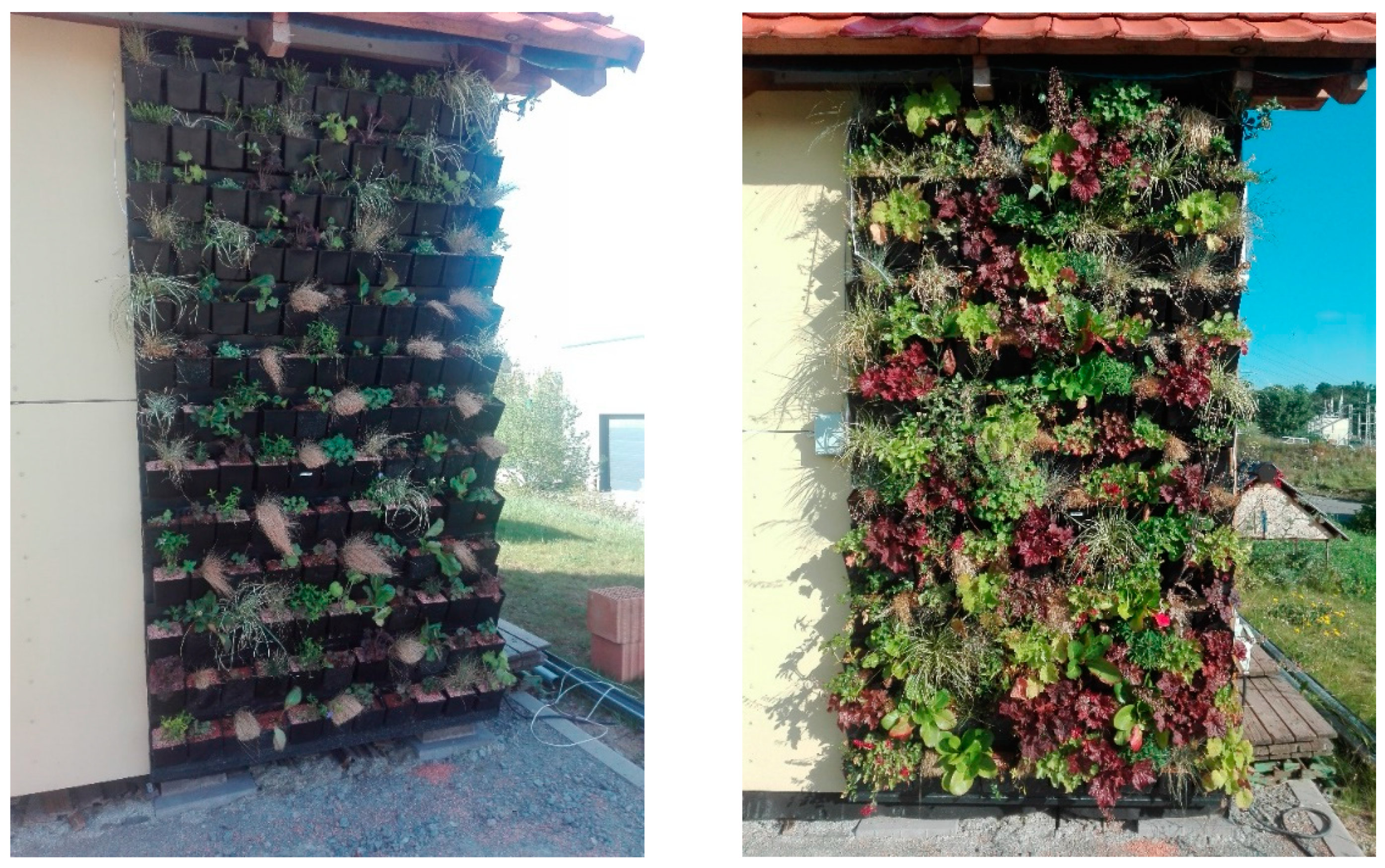
1]. There are many solutions to this issue, as shown by the Mediterranean countries and others located in tropical or subtropical zones. Since time immemorial, the countries of Southern Europe have used various shading techniques, coatings and reflective elements, as well as green climbing plants, to cover the facades and roofs of buildings, thus reducing the surface temperature of the exterior as well as the temperature inside the building. In recent decades, there has been a trend towards using green facades (
Figure 1), roofs and walls, or dynamic green facades that can be moved as needed [
2,
3]. These elements are described as natural tools to reduce the energy demand of the building sector in the EU’s 2013 Commission Document 249 2013, titled “Green Infrastructure—Enhancing Europe’s Natural Capital” [
4], and its Directive 2018/844 on energy efficiency [
5]. Green elements (green facades, green walls, green roofs) positively affect the thermal area [
6,
7,
8,
9,
10] and capture a considerable number of dust particles and air pollutants [
9]. They also have a positive effect on the acoustics of buildings [
9,
11]. In large cities, they reduce the temperature of the surroundings, or the so-called “heat islands” [
6,
7,
8,
9,
12], which is where overheating often occurs due to urbanization. Last but not least, they have a positive effect on inhabitants’ psychological and physical health [
9,
10,
11]. Thanks to these elements, heat transfer and energy flow can be effectively controlled while reducing the cooling and heating requirements of buildings [
12,
13,
14].
However, when it comes to reducing the energy requirements of buildings, as well as meeting the requirements for the thermal protection of buildings in each country (including those specified in the above-mentioned directive 2018/844 on energy efficiency [
5]), it is currently necessary to also use thermal insulation materials that are built into structures to ensure the required thermal insulation properties. These materials are either directly built into the structures or form an external (or internal, as is obvious from a lot of the research conducted in this area, for example, H2020 RiBuild) [
15] insulation system.
For some buildings (especially in the case of renovations), it is very difficult to install thermal insulation in greater thicknesses from the outside or inside of the structure. In such cases, a suitable solution is to install vacuum insulation panels (VIPs), which are thinner than conventional insulating materials as they have a 5–10× lower coefficient of thermal conductivity. As a result, they can meet the requirements for the thermal protection of buildings at a significantly reduced thickness.
Currently, VIPs are used in the glass façade systems of vertical building envelopes, specifically in non-transparent elements (window panels), or in special types of buildings based on reinforced concrete. It is also possible to use VIPs in some types of modern wooden buildings [
16,
17,
18].
The idea of connecting super insulating materials with green elements/facades arose during a research project carried out by the Faculty of Civil Engineering in Brno and Ljubljana, which are jointly engaged in a project to study the thermal properties and reduced lifecycle impact of alternative hybrid eco-nanomaterials under low pressure [
19]. Both faculties have been dealing with this issue for many years [
12,
20,
21,
22,
23,
24]. Together, they came up with the concept of a thermal insulation panel that would serve as a base for anchoring a green wall/façade, displaying significantly better mechanical properties than the ETICS system of the same thickness, primarily because of the greater protection offered by this sensitive material when integrated into a vertical green wall/facade system.
As mentioned above, green facades and vacuum insulation panels are both well-developed technologies, but there is a lack of work that connects the two. By combining these two important elements, it is possible to achieve a highly effective, ecological thermal insulation system that could be a solution for reducing the energy demand of buildings, both existing and new. In the summer, this system would primarily help to reduce cooling requirements, limiting the use of air-conditioning units. In the summer, the green facade reduces the thermal load of the building envelope caused by solar radiation, and the vacuum insulation simultaneously increases the thermal resistance of the envelope, while, in the winter, the green facades and vacuum insulation increase the thermal resistance of the envelope. In addition, green facades reduce the influence of climatic factors (wind, snow). In winter, this would help save energy when heating, which is currently a critical issue for European countries. Another significant advantage, especially during building renovations, is the significantly reduced thickness of the proposed insulation system using green elements.
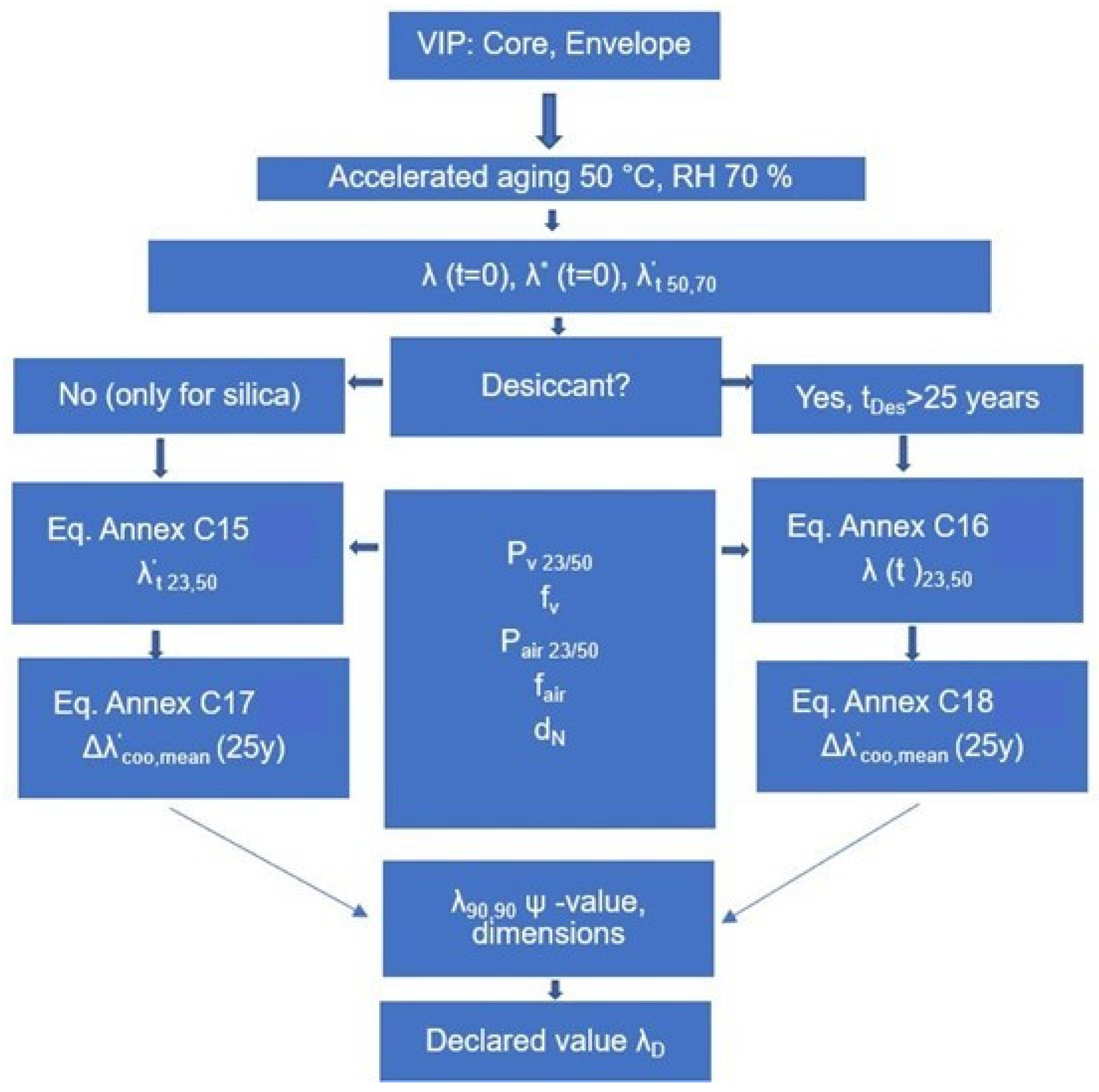
Figure 1.
Ageing procedure according to EN 17140 [
25].
Figure 1.
Ageing procedure according to EN 17140 [
25].
2. Vacuum Insulation Panels
Vacuum insulation panels belong to the group of super insulation materials (materials with a thermal conductivity lower than 0.023 W/(m·K)). According to EN 17140, they are thermal insulation materials consisting of an airtight and watertight outer layer, an envelope around a core insulation material with a high open porosity, where the pressure inside the envelope is reduced below the ambient atmospheric pressure. VIPs can also contain additional substances for gas absorption getters or desiccants [
25,
26]. VIPs have superior thermal insulation properties compared with traditional thermal insulation materials (a 5–10 times lower coefficient of thermal conductivity) [
27,
28], with significantly lower thicknesses. When using a vacuum insulation panel with a thickness of 40 mm, it is possible to reach the passive house standard for the thermal insulation parameters of vertical walls [
28]. As a result, vacuum insulation panels have considerable potential when it comes to the effective thermal insulation of building envelopes in the near future [
29,
30,
31,
32,
33,
34].
When it comes to the core of VIPs, a suitable material has a completely open pore structure, with an ideal pore size of up to 100 nm. Furthermore, they must be able to withstand an external atmospheric pressure of at least 1 bar. Core materials can be composed of one of three basic materials: micro(nano)porous powders, micro(nano)fibres and foams. Each of these materials has its own unique properties and can be used for different types of VIP. Under normal pressure, the core insulating materials show a very low thermal conductivity, at the level of poorer types of thermal insulation (mostly in the range of 0.024–0.031 W/(m·K)), and, after the pressure is reduced in their structure, the thermal conductivity drastically decreases, usually to a level of around 10% of the original value). The core insulating materials usually have higher bulk weights, which are associated with the need to withstand relatively high atmospheric pressure and possibly other loads.
Currently, the most used core insulation materials include fumed silica, glass fibres and aerogels. You can also find alternative materials from easily renewable sources and from secondary raw materials, or use cheaper variants of the materials mentioned previously. When it comes to their application in the field of construction, core materials based on fumed silica or aerogels are used in most cases, because they provide a longer life compared to core materials based on glass fibres or other alternative materials. Due to the very fine structure of core materials based on SiO
2 (fumed silica or air-gel), there is a minor change in thermal conductivity when the pressure changes in their structure. With VIPs that use these materials, it is therefore not necessary to maintain as low a pressure inside as you would with VIPs based on other core materials. It is also possible to use barrier envelopes with lower thermal conductivity (with a lower proportion of aluminium foil), which reduces the degradation of the thermal properties of the VIP layer due to the edge effect [
30,
31].
The VIP envelope usually consists of three layers: a sealing layer (most often based on polyethylene foil), a protective layer (mostly based on polyester foil) and an air-tight barrier (based on aluminium foil). The sealing layer is the inner layer and ensures that the panel core in the envelope is sealed, which is achieved by thermal bonding under high pressure. This is an important process as it ensures that the vacuum is maintained and affects the lifespan of the VIP. The middle layer consists of a barrier that prevents the passage of water vapour and gases. Among the most commonly used materials for this envelope layer are aluminium foil and multi-layer laminate. The outer layer protects the entire insulation panel from the effects of the surrounding environment and from mechanical damage. For this layer to fulfil its function, it should be robust and thus protect the product during its installation and transportation. The main functions of the envelope include ensuring the airtightness and water-vapour impermeability of the VIP core. Since the thermal insulation properties of VIPs are highly dependent on maintaining a vacuum inside, any gas or vapour that penetrates them would damage the efficiency of the entire panel. For this reason, the envelope must be made of a material that is not susceptible to mechanical damage during its application and is, at the same time, resistant to external phenomena such as changes in temperature and humidity. Other factors to consider include preventing thermal bridging at the edges of the VIP. From a material point of view, these are very thin materials with a thickness of 100–200 nm, most often made from plated polytetrafluoroethylene foils [
29,
32]. Studies have shown a dependence between the plating thickness of a single-layer foil and the reduction of the permeability of the entire envelope when the significant limit of aluminium plating was determined to be 20 nm. The aluminium layer on the foil creates a natural protection against corrosion due to oxidation in an aggressive environment. The exception is chloride ions, which can degrade the plated layer, resulting in significant changes in the parameters of the VIP envelope [
33].
The third component of VIPs may or may not be desiccants or getters. It depends on the capabilities of the core material in terms of its hygroscopicity and gas adsorption capacity, possibly also improving the sealing layer of the core. The low coefficient values of thermal conductivity in VIPs are dependent on low gas contents (vacuum purity) inside the VIP. Gases and atmospheric moisture in the form of steam can penetrate the sealing layer of the VIP envelope, negatively affecting its super-thermal insulation capabilities. Getters represent materials capable of binding gases from the residual atmosphere of the vacuum system on their surface, effectively reducing the pressure within the envelope. Desiccants are hygroscopic substances that trap moisture [
25,
31].
2.1. The Use of Vacuum Insulation Panels in Construction
Vacuum insulation panels have been the subject of many studies over several decades of development and research. The first studies of VIPs took place in 1930 [
27]. While insulating panels have long been used in the refrigeration industry and in the production of shipping containers [
28], they were not used extensively in the construction industry until the 1990s [
35]. Currently, several organisations within the European Union and across the world are dedicated to the development of VIPs and their application in the construction industry: Switzerland, Germany, Canada, USA, Italy, Scandinavian countries, Great Britain, several Asian countries and, last but not least, the Czech Republic and Slovenia [
27,
28,
30,
32,
35,
36]. In the construction industry, VIPs are used in the insulation of facades, including reconstructions (ETICS) [
29,
32,
35], the construction of flat roofs [
37] and the production of prefabricated reinforced concrete sandwich panels [
38].
Currently, it is estimated that roughly 20% of manufactured vacuum insulation panels are used in the construction industry [
31]. The growth of that rate is currently hindered due to high costs, high energy requirements in the production phase, a shorter lifespan than the buildings themselves, insufficient experience with assembly and little knowledge of the behaviour of insulating panels in real applications [
27]. The two most pressing factors, however, are the high costs and the lifespan of the panels.
The high energy demand in the production phase can be mitigated by using suitable materials for the filling of the vacuum insulation panels. In the case of insufficient experience with assembly and knowledge of the behaviour of insulating panels in real structures, several applications are being developed across the world [
28,
29,
32,
35].
2.1.1. Lifetime of Vacuum Insulation Panels
The service life of VIPs is very specific compared to that of other insulation materials. According to EN 17140, the estimated service life is set at 25 years [
25]. However, this property is negatively affected by the penetration of atmospheric gases (N
2, O
2 and H
2O) through the envelope into the core of the panel. This results in an increase in internal pressure, i.e., an increase in gas conductivity as well as moisture inside the pore structure of the panel core. The increase in pressure inside the panel is limited to a maximum of 100 mbar [
38]. Closely related to this is the increase in the coefficient of thermal conductivity in VIPs, i.e., the deterioration of the thermal insulation properties [
31]. With the use of some core materials, such as pyrogenic SiO
2, ageing is also an important factor (in addition to the previously mentioned factors) when it comes to an increase in the area between individual particles—an increase in heat transfer by conduction [
36]. According to the literature, the increase in the coefficient of thermal conductivity per year for vacuum insulation panels is 2% [
29]. Studies have shown a service life of more than 10 years for the first applications of VIPs, with an assumption of 25 to 40 years [
35,
39]. According to the latest studies, the coefficient of thermal conductivity after 25 years of use is in the range of 0.006–0.0086 W/(m·K), and, after 50 years, it is approx. 0.0079–0.0105 W/(m·K) [
31]. The service life of VIPs can be described as a function of several basic parameters, such as the size of the panel (larger panels are expected to have a longer service life), the quality of panel production, the core material used (materials with a smaller pore size are expected to have a longer service life), the application environment and conditions of use (high humidity and temperature fluctuations) and the physical handling (mechanical damage). The usual size of vacuum insulation panels is approx. 600 × 600 mm, with smaller panels being approx. 400 × 400 mm, and larger ones approx. 1000 × 600 mm (due to the ratio of area and circumference, the minimum size should be 150 mm) [
29]. Due to their susceptibility to mechanical damage, vacuum insulation panels are very often part of sandwich structures, where some of the layers of the structure protect the panel [
28,
29]. These are mainly layers of mineral wool, foam and extruded polystyrene [
27,
30,
32,
35].
According to EN 17140, the thermal conductivity of VIPs evolves during their implementation, and an evaluation of these effects is necessary. Factors that can change the thermal performance include an increase in the internal gas pressure or the moisture content and any changes in the structure of the core material or envelope. The principle of the ageing procedures used here is described in
Figure 1 [
25].
Accelerated ageing at a higher temperature (50 °C) and relative humidity (70%) is measured over 180 days. Measurements of thermal conductivity are made after 60, 90, 120 and 180 days of the storage of the test samples, according to EN 12667 [
26]. During accelerated ageing, the increase in thermal conductivity, gas pressure and mass (moisture content) is measured. The accelerated increase of the thermal conductivity is then reduced to normal conditions (23 °C and RH 50%), revealing the properties of barrier films relating to air permeability and water vapour as a function of temperature.
For materials with a silica core, the influence of moisture is dominant, whereas, for cores that contain a desiccant, a change in air permeability is the dominant factor when it comes to increases in thermal conductivity. This is why two different formulae apply for both cases. The ageing procedures are used to calculate an average value of the thermal conductivity at the centre of a panel over a 25-year period [
25].
The coefficient of thermal conductivity for the conditions θ = 50 °C and RH = 70% can be determined from the following linear equation:
The coefficient of thermal conductivity for the conditions θ = 23 °C and RH = 50% can be determined from the equation below:
—change in thermal conductivity with time,
—interpolated initial value,
t—time.
As the facts above show, the lifetime of a VIP is fundamentally influenced by the temperature and relative humidity of the environment in which it is installed. Before the publication of EN 17140, several studies were carried out that dealt with the issue of VIP ageing and the factors that influence it, to set the conditions for determining accelerated ageing according to EN 17140 in an appropriate way. They mainly focused on the activities described in the IEA-EBC Annex 39 and the subsequent Annex 65 [
31,
39]. In addition to these activities, several research teams have devoted themselves to studying VIP use in conditions such as an increased temperature and relative humidity [
40,
41].
From this point of view, it can be concluded that connecting VIPs to a green facade could also be advantageous in terms of the lifetime of the VIP. Due to the influence of the green facade, the temperature stress on the VIP will be reduced, and its lifetime will increase as a result.
2.1.2. Economic Aspect of the Use of Vacuum Insulation Panels
The current global vacuum insulation panel market was estimated at €5.9 billion in 2020 and is expected to reach €8.2 billion by 2027. The total share of the insulation materials market is less than 1% [
35]. The costs associated with the use of VIPs can be set at €3000/m
3. The high costs associated with the application of VIPs in the construction industry are not only associated with the price of the panels themselves but also with the need for detailed planning and increased labour during their application, i.e., labour costs. The current increase in energy prices is one of the factors that significantly influences the cost comparison of the use of VIPs in the construction industry [
35]. A study that evaluated the return of VIPs on building facades in relation to rental prices in the world’s capitals also provided an interesting perspective. Depending on the rental prices, the return on the use of VIPs has been determined to be 6 to 20 years [
35].
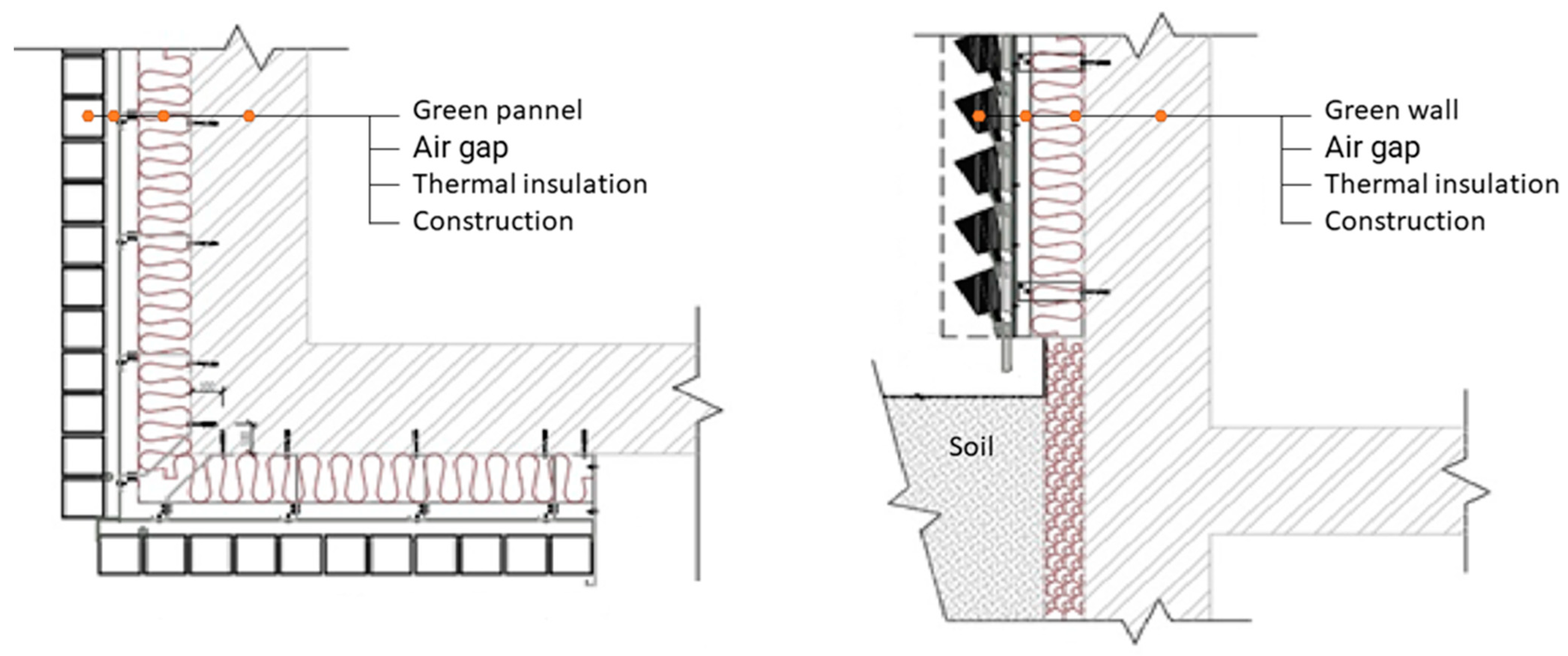
3. Options for Installing Green Walls on Insulated Building Structures
Green walls are directly anchored to the cohesive surface of building facades or to separate load-bearing structures (
Figure 2), many of which also need to be anchored to a building’s surface (but at a significantly lower frequency than that of systems installed directly to the surface of the structure) (
Figure 3).
In cases where a green wall is to be installed onto the surface of a structure (e.g., new buildings with additional thermal insulation), it is quite complicated to anchor the green wall to the structure without a dedicated support system. Among other things, the relatively high U values demanded by current building regulations, as well as energy-efficiency standards, result in higher thicknesses of conventional thermal insulation materials (100–200 mm).
The idea of utilising VIPs in green walls arose as part of a joint research project in the field of VIPs conducted by the Faculty of Civil Engineering in Brno and the Faculty of Civil and Geodetic Engineering in Ljubljana. The main reason was the possibility of greater protection for sensitive VIPs when incorporated into a vertical green wall/facade system. By connecting these two important elements, a very efficient, ecological, thermal insulation system can be achieved, which could be one of the possible solutions for reducing the energy consumption of buildings, both existing and new. In the summer, this would help to reduce cooling requirements, limiting the use of air conditioning units. In the winter, the system would reduce thermal losses, resulting in the use of less heating energy. As a result, this solution addresses the need both to adapt to climate change and to reduce energy usage. Both are critical strategic topics for the EU and its member states. Another significant advantage of implementing VIPs, especially for building renovations, is the significantly lower thickness of the insulation system. A thermal insulation panel serving as the base for anchoring a green wall, with significantly better mechanical properties than an ETICS system of the same thickness, is being developed as part of the research work.
4. Methodology
4.1. Insulation Panel Concept for Anchoring of Green Walls
The basic idea of the proposed VIP insulation panel for anchoring green walls is based on the following fundamental principles:
Super insulating materials (i.e., VIP) will be used to reduce the panel thickness and achieve high thermal insulation properties;
The panel must be formattable;
The panel must enable anchoring to the supporting structure;
It must be possible to anchor the green wall structure to the panel surface.
Super insulating materials will be used to reduce the overall thickness of the panel, while the insulation layer of the panel will be divided into two parts:
The first part, adjacent to the load-bearing structure, will consist of a conventional thermal insulator with appropriate mechanical properties, such as extruded polystyrene (XPS), which will also protect the primary VIP thermal insulation layer on one side. XPS, which is currently used, has a thermal conductivity range of 0.033–0.036 W/(m·K). In this case, XPS with a stress at 10% deformation of at least 300 kPa will be used.
The second layer of insulation will consist of a combination of a vacuum insulation panel and rigid polyurethane foam (PUR) with a very low thermal conductivity coefficient of 0.021 W/(m·K).
On the external side, the panel will be fitted with a rigid structure board, e.g., based on cement fibre or cement particle board, which will allow the direct application of green wall elements without requiring further modifications. The panel elements will be bonded using a polyurethane adhesive.
To make the panel formattable and to be able to anchor into it (both the green façade to the panel and the panel to the substrate), the main thermal insulation layer will be divided into VIP and PUR parts. The final structural panel will be modified by shallow grooving and grinding so that the VIP and PUR parts can be separated from each other. The VIPs will be placed in a grid and separated from each other horizontally and vertically by gaps filled with PUR sections, through which the panels can be divided (i.e., formatted) and anchored. These panels will be complemented by panels made exclusively of PUR foam, from which it will be possible to make atypical cut-outs and cut-offs in order to adapt the system to the geometry of the entire surface of the façade. The system will also include mouldings and accessories to mark the end of the system vertically and horizontally.
4.2. Optimisation of the Insulation Panel
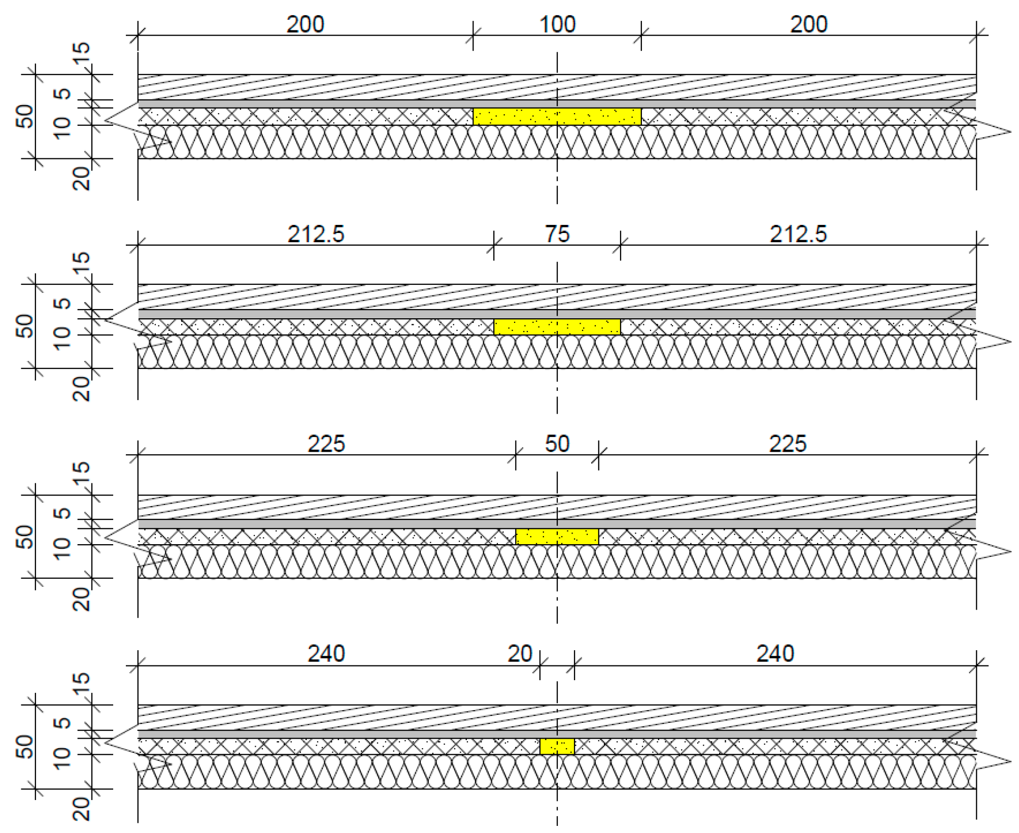
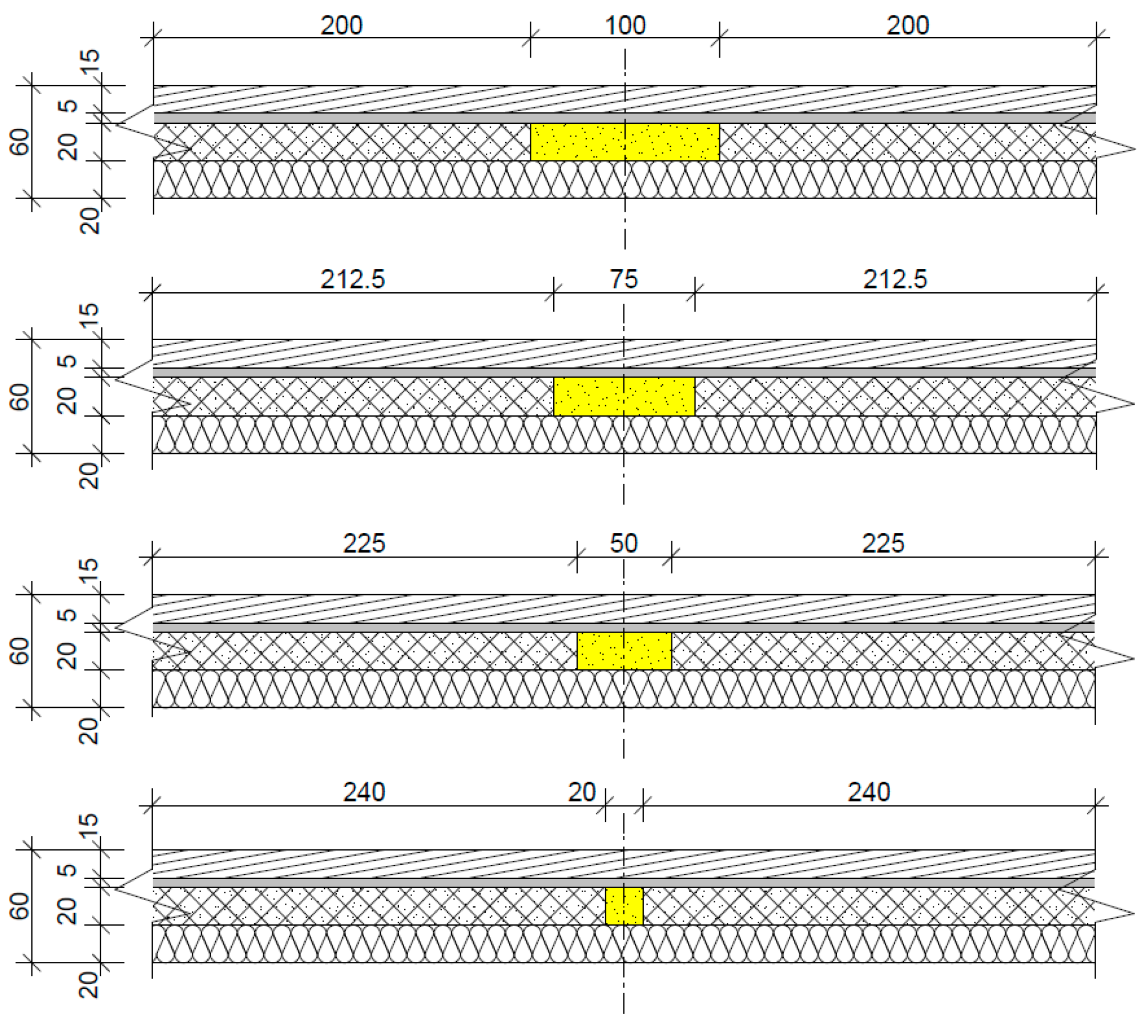
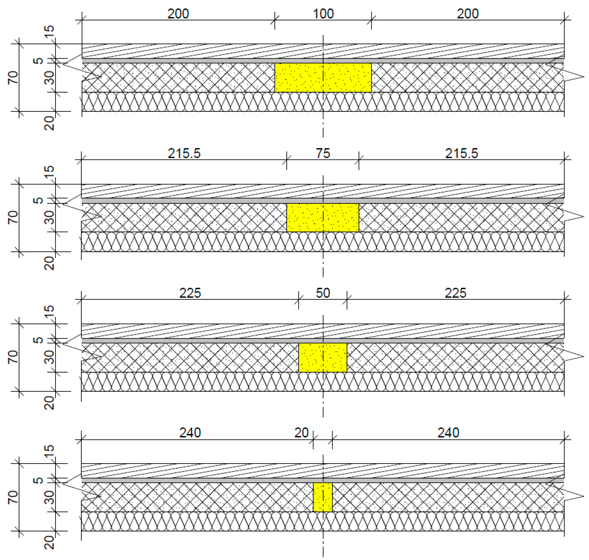
The aim of the work in the initial design phase was to optimise the panel layout in terms of the size and thickness of each of the insulating elements and to determine the basic thermal properties of the panels for each layout and thickness case (
Table 1). In terms of thickness, the following panel compositions were considered:
The panel’s total thickness will theoretically range between 50 and 70 mm, which is one-half to one-third the thickness of conventional insulation systems. In terms of the area representation of VIP vs. PUR, a basic grid of 500 × 500 mm was considered. Joints between the VIP of 20, 50, 75 and 100 mm in both directions were considered; see the schematic drawings in
Figure 4,
Figure 5 and
Figure 6. In the calculation part, a gap of 0 mm and 500 mm was also considered (
Table 2).
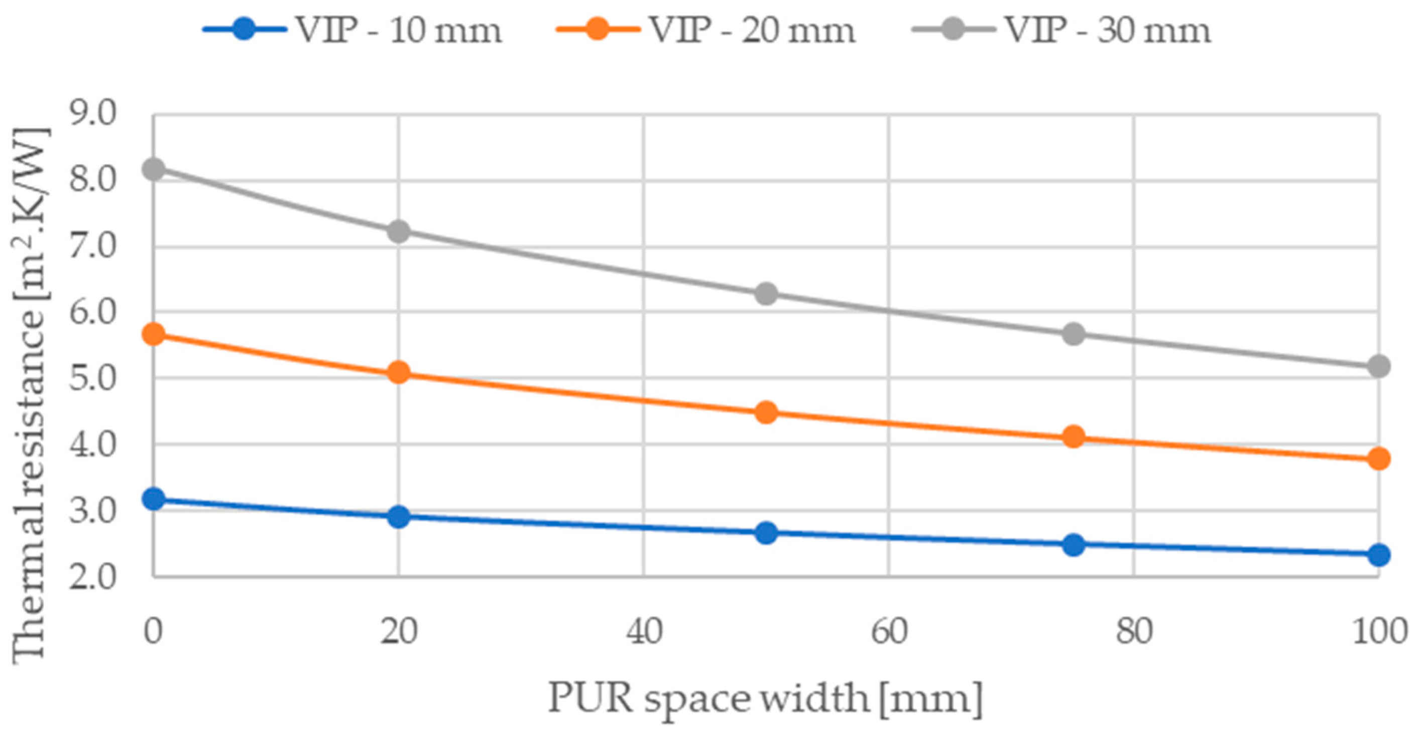
5. Calculation Results
A total of 18 models were created (see above), considering gap widths of 0, 20, 50, 75, 100 and 500 mm for each VIP thickness variant. The 0 mm gap width represented a situation in which the VIPs would form a continuous layer (i.e., a theoretically achievable limit value), and the 500 mm width represented a situation in which the VIP would not be built into the structure, and the insulator would only be a combination of PUR and XPS.
The calculation models were loaded with boundary conditions typical for the Czech Republic (i.e., an outside air temperature of −15 °C and an inside air temperature of +21 °C). Calculations were performed using the finite elements method, in accordance with EN ISO 6946 [
43]. The summary results are shown in
Table 2.
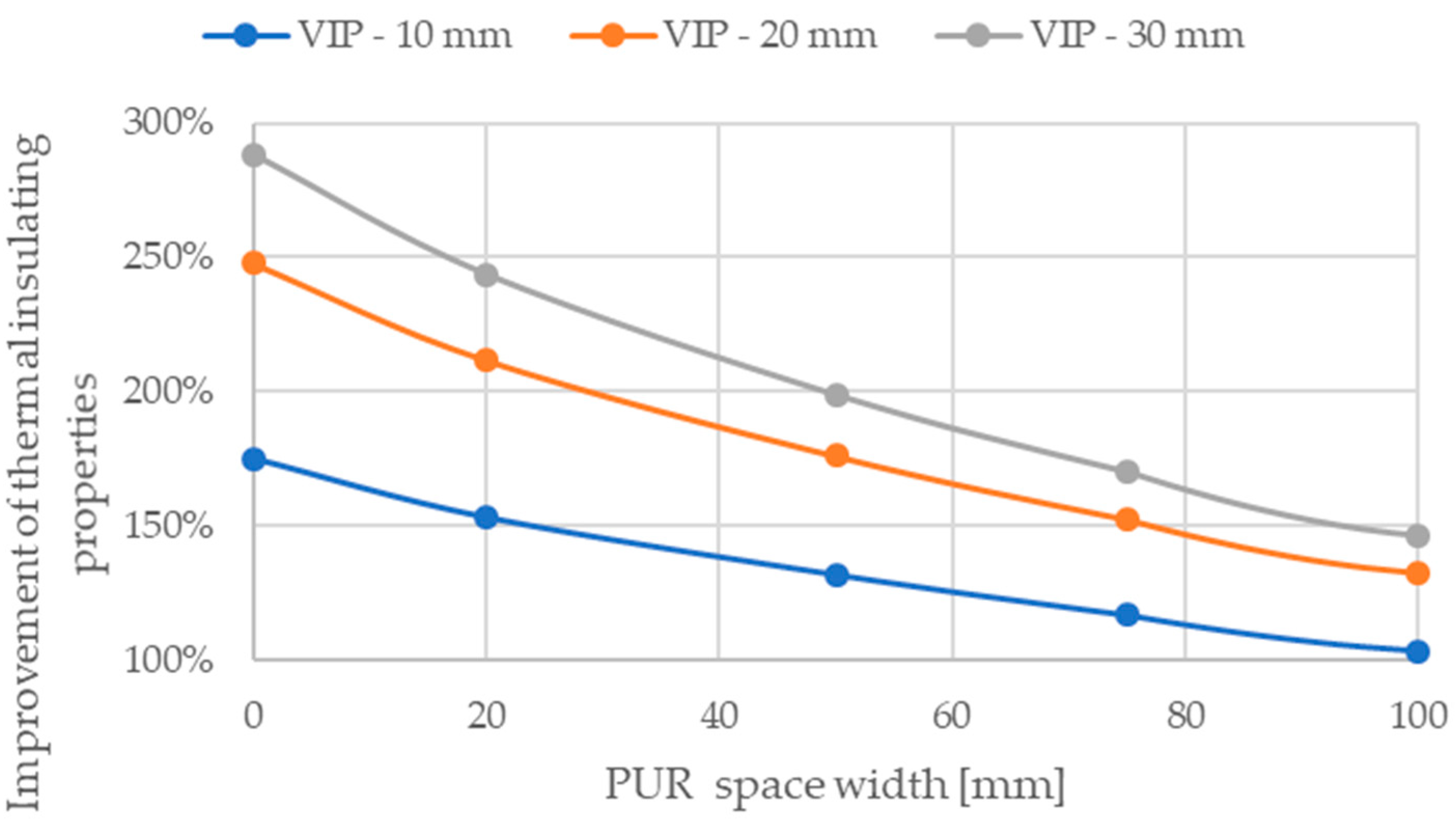
As can be seen from the calculations, the gap between the VIP panels strongly affects the thermal insulation properties. For the considered module of 500 × 500 mm, gaps between VIPs in the range of 20–100 mm were considered. Compared to a situation where the entire space would be filled with only hard PUR foam, the use of VIPs will result in a possible improvement in thermal resistance in a range of 103% to 244%, depending on the thickness of the VIP, with the effect increasing as the thickness of the VIP increases. In the instance of a smaller gap of 20 mm, which can be considered the minimum allowing for the installation and anchoring of panels, where it can be assumed that such a gap could be sufficient when using a smaller thickness of VIP, you would achieve a 153% improvement in thermal resistance in the instance of a 10 mm VIP, a 212% improvement for a 20 mm VIP and a 244% improvement for a 30 mm VIP. In contrast, a gap width of 100 mm, considered a limit variant, is too high for all VIP thicknesses, and free-anchoring will be possible even with smaller gap widths (depending on the VIP thickness). However, even using a 100 mm gap, a significant improvement in thermal resistance can be achieved using VIPs, namely, a 103% improvement for a thickness of 10 mm, 132% for a thickness of 20 mm and 146% for a thickness of 30 mm (
Figure 7 and
Figure 8).
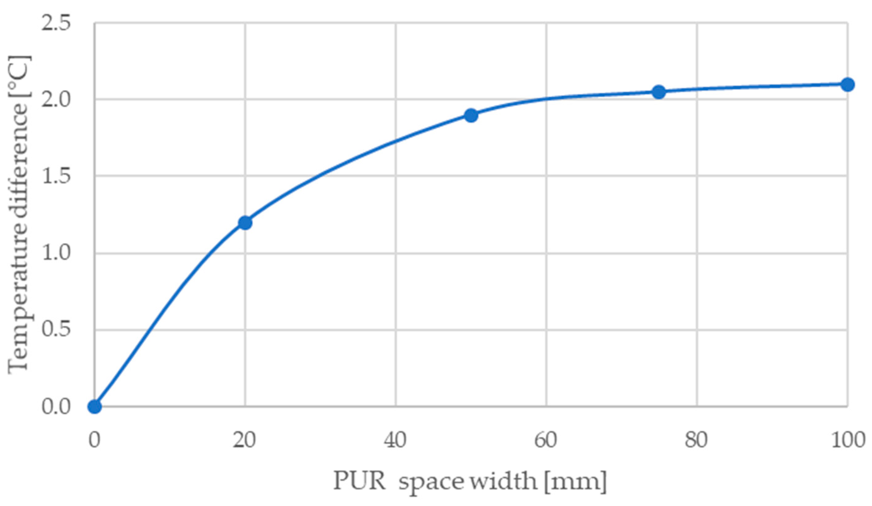
The calculations found that the greatest negative influence on the temperature field occurs in the variant with a 10 mm VIP. The temperature drop in the middle of the joint affected by PUR foam was 2.1 K in the case of a 100 mm gap width (compared to a continuous VIP layer). For the 30 mm VIP variant, there was a drop of only 1.4 K (for the 100 mm gap variant). The temperature difference along the inner surface of the panel for individual widths of the gap with PUR foam for a panel with a 10 mm VIP thickness is shown in the following graph
Figure 9:
6. Discussion
As part of the research work carried out in this study, a conceptual design of an insulating panel utilising VIPs and allowing the anchoring of a green facade to the surface of the structure was developed. Different model configurations were considered from the point of view of the thickness of the vacuum insulation, which would represent the main thermal insulator in the system, with PUR gaps between them. The main purpose of including PUR peripheral gaps was to allow for the mechanical anchoring of the system to the surface of the structure (including the anchoring of a green wall system to the panels). Three VIP thicknesses of 10, 20 and 30 mm were considered. In the end, the total thickness of the entire panel, including all other layers (i.e., XPS and construction board), was 50, 60 and 70 mm, which is significantly lower than the thicknesses of standard ETICS systems. The thermal properties of the panels significantly exceed the properties of ETICS of comparable thicknesses. In the given case, it was found that the variant with the 10 mm VIP is advantageous in terms of anchoring because it is possible to use a smaller distance between VIPs. However, the effect of improving the thermal insulation properties due to a thinner VIP is the lowest here compared to the other cases. Taking into account the resulting properties and the properties of the panel without a VIP (e.g., a situation where the VIP in the panel would be damaged), it can be argued that the best option would be a 30 mm VIP and a PUR gap of 50 mm. This configuration would allow for the trouble-free division of the panel anchoring (20 mm appears to be an insufficient width given the thickness of the panel). The thermal resistance of the exposed panel is 6.29 m
2·K/W, which corresponds to 220 mm of EPS or mineral wool (with a coefficient of thermal conductivity λ
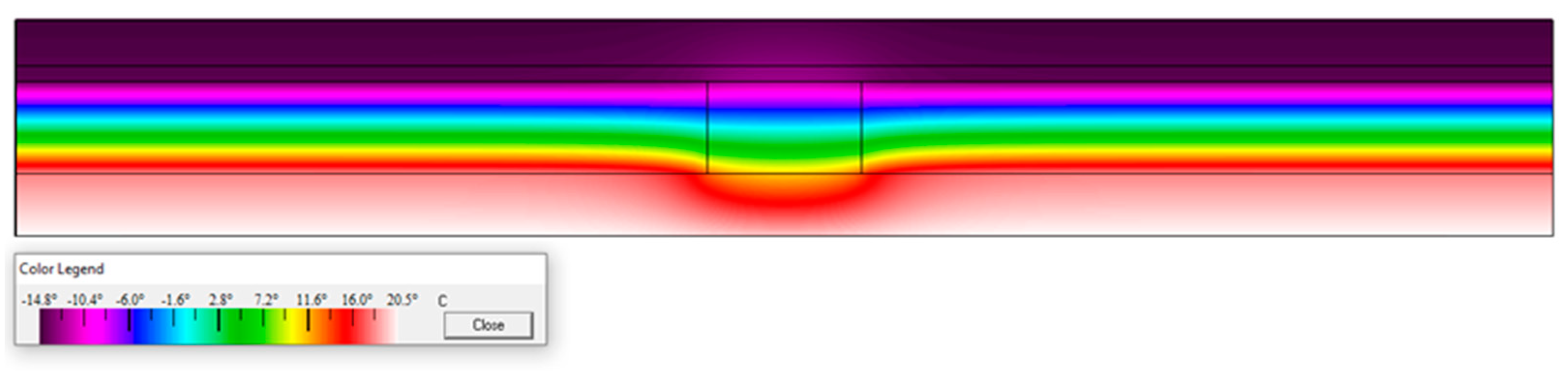
D = 0.035 W/(m·K)). Let us consider that the thickness of the panel is a total of 70 mm. This would mean that the thickness of the insulation system would be reduced to less than 1/3, with the further benefit of having a solid structural plate on the surface of the panel that allows the anchoring of other elements (e.g., planter boxes for the green wall system) to the panel. In the exposed configuration, the temperature drop at the point of the VIP–PUR contact is only 1.2 K (
Figure 10).
7. Conclusions
It can be concluded that VIPs, in combination with elements of green architecture, have a high potential for application due to their lower thickness, high thermal resistance and ease of use. Nevertheless, further research and development work will be necessary to investigate their performance as related to building physics and fire safety, as well as to cost benefits and durability. In the case of further positive results in the development of this non-traditional VIP-and-green-facade system, it will possible to assume that there are additional non-traditional yet effective combinations of vacuum insulation panels with other elements that reduce the energy demand of buildings, in addition to the currently used combination of vacuum insulation panels and glazed facades (into non-translucent parts), possibly including the use of VIPs in wooden buildings and concrete sandwich structures [
15].
In the given case, it can also be assumed that the green wall will significantly change the temperature stress of the VIP built into the facade, which will have the positive effect of reducing the rate of degradation of the thermal properties of the VIP over time in areas with higher solar activity, where the VIP could be negatively affected during high summer temperatures.
Lastly, this system of proposed sandwich panels can also be used as a replacement for the commonly used ETICS systems, even in cases where the installation of a green wall is not required. Various types of surface treatments can be applied to the construction board. The structural plate will also reinforce the structure’s surface, and the resulting system will have better mechanical properties than a conventional ETICS system’s surface.


 ,
, 


