Abstract
Recycled aggregate concrete (RAC), composed of aggregates sourced from construction solid waste, has garnered significant attention owing to its notable environmental friendliness. In this study, waterborne epoxy resin (WER) and steel fibers (SFs) were introduced into the RAC to enhance its performance. Orthogonal tests were meticulously designed, with the substitution rate of recycled aggregate (RA), SF dosage and WER dosage as variable factors, to comprehensively analyze the splitting tensile strength and impact resistance of concrete. The impact resistance of concrete was investigated via the drop weight test method. Furthermore, scanning electron microscopy (SEM) was employed to scrutinize the microstructure of concrete, investigating the modification mechanism of WER. The results indicated that the addition of SFs exerted the most pronounced influence on the properties of RAC. As the addition of SFs increased from 0 to 1.0%, there were significant enhancements in the splitting tensile strength and impact energy of the specimens. WER exhibited notable improvements, primarily on the splitting tensile strength, while demonstrating an adverse effect on the impact resistance. Utilizing the Weibull distribution theory, the results of the impact tests were fitted and analyzed to predict the impact life of different mixtures. The predicted results showed high correlations with the measured values.
1. Introduction
With the global urbanization trend, the burgeoning construction industry has escalated the demand for concrete materials, particularly natural aggregates (NAs) that serve as key components in concrete production. At the same time, the demolition of buildings generates a large amount of construction solid waste, primarily comprised of waste concrete. Traditional disposal methods, such as conventional landfills, not only consume extensive land resources but also result in soil quality degradation, rendering the management of construction solid waste a pressing concern. Recently, guided by the principles of resource recycling, waste concrete blocks undergo a series of processes, including crushing, cleaning, and screening, to obtain recycled aggregate (RA). The RA is subsequently blended in specific proportions and grades, partially or entirely replacing NA to create recycled aggregate concrete (RAC). On the one hand, the use of recycled resources reduces the demand for natural aggregates and reduces the exploitation of natural resources. On the other hand, it realizes the reduction, harmlessness, resourcefulness and industrialization of construction solid waste. In addition, research by related scholars shows that incorporating RA in concrete production significantly reduces carbon dioxide emissions during the manufacturing process, which brings considerable economic and environmental benefits [1,2]. However, the high water absorbance and pressure crushing index of RA, and the more microcracks on the surface of RA, result in the mechanical properties of RAC generally being lower than those of natural aggregate concrete (NAC), which restricts the promotion and application of RAC [3]. In particular, the recycled concrete structures applied in road engineering, bridge engineering, etc., will not only bear static loads but also may be subject to the impact of water flow, explosions, vehicle impact and other sudden and destructive dynamic loads and seismic waves. A study by Lu et al. [4], utilizing split Hopkinson pressure bar tests, revealed that, in comparison to NAC, RAC exhibited a lower dynamic increase factor and reduced energy absorption capacity. Additionally, Rao et al. [5] have observed that when the RA substitution rate surpasses 25%, the responses of RAC under a given drop weight impact load deteriorate while strain levels increase. Therefore, it is of vital significance to carry out research on the damage morphology, mechanical properties and impact life of RAC under impact loading to enhance the safety of RAC structures, as well as to provide an experimental basis for the popularization and application of RAC.
Currently, scholars have conducted extensive research aimed at enhancing the mechanical properties and impact resistance of RAC, achieving promising outcomes [6,7,8]. Prior investigations have demonstrated that the introduction of fibers can markedly enhance the mechanical properties of RAC. In particular, the addition of steel fibers (SFs) can effectively enhance the impact resistance of RAC through bridging action and micro-reinforcement. Omidinasab et al. [9] observed that a 100% replacement of RA resulted in a significant decrease in both the mechanical properties and impact resistance of concrete. However, the inclusion of SFs effectively counteracted the adverse effects of RA on the mechanical properties and impact resistance of concrete. Jahandari et al. [10] further demonstrated that the mechanical properties and impact resistance of RAC decreased with the increase in RCA substitution rate, while it was substantially enhanced through introducing SFs. Furthermore, numerous experimental studies have consistently revealed a characteristic feature of steel fiber-reinforced recycled aggregate concrete (SFRAC) damage: SFs were pulled out from the fracture surface without being broken off, which indicates that the SFs enhance the toughness of concrete through the fiber pull-out effect. The bond at the interface between the SFs and the concrete matrix relaxes stresses at the crack tip, delaying crack propagation [11,12]. Thus, the bond at the SF–concrete matrix interface is pivotal in determining the toughening effect of SFs in RAC, warranting in-depth research into the modification of this interface.
The incorporation of polymers stands as a widely employed approach for interfacial modification in concrete studies. Through interactions between polymer film-forming and cement hydration processes, the properties, pore structure, durability, flexibility and bonding of concrete are all enhanced [13,14,15]. Among these polymers, waterborne epoxy resin (WER), as a water-soluble polymer with good compatibility with concrete, has been widely used in cementitious composites in recent years. WER exhibits a reduced quantity of volatile organic compounds (VOCs) in comparison to conventional solvent-based epoxy resin, leading to diminished emissions of VOCs and CO2 throughout its production and application. Owing to its non-toxic, harmless and eco-friendly characteristics, WER has emerged as the predominant polymer for concrete applications. Pang et al. [16] innovatively developed a novel waterborne epoxy resin concrete composite repair material (WECM) utilizing self-synthesized waterborne epoxy resin. The test results revealed that the ductility of WECM was enhanced by 300% to 600% compared with ordinary concrete, and the waterborne epoxy resin and fibers in WECM showed synergistic enhancements to the tensile strength and ductility of the concrete. Additionally, Farooq and Banthia [17] demonstrated that the addition of epoxy resin significantly reduced concrete porosity, further enhancing concrete performance in conjunction with fiber reinforcement. However, there are few studies related to WER-modified steel fiber-reinforced recycled aggregate concrete, especially regarding the impact resistance of concrete. The modification effect and mechanism of waterborne epoxy resin on the interface between steel fibers and concrete matrix have not yet been thoroughly researched. Therefore, it is of great significance to carry out research on the impact resistance and modification mechanism of WER-modified steel fiber-reinforced recycled aggregate concrete.
In this study, an orthogonal experimental design was employed to analyze the splitting tensile strength and impact resistance of WER-modified SFRAC through considering the replacement rate of RA, the dosage of SFs and the dosage of WER. The aim was to investigate the modifying effects of WER on SFRAC. Furthermore, the internal microstructure of concrete was observed using scanning electron microscopy (SEM) to explore the modification mechanism of waterborne epoxy resin. Additionally, a dual-parameter Weibull distribution model was applied to fit and assess the results of impact tests, enabling the prediction of impact lifetimes for various test specimens under different failure probabilities.
2. Experimental Program
2.1. Materials
Ordinary Portland cement (OPC) was used in this study. Fine aggregate in this study consisted of locally sourced river sand with good particle grading, while natural gravel with a continuous particle grading of 5–16 mm served as the natural coarse aggregate. As the construction solid waste primarily consists of waste concrete produced after the completion of construction services, we selected waste concrete blocks from nearby demolition sites to create RA. These blocks had not been exposed to specific corrosive environments, ensuring the quality of the RA. After the initial manual crushing and removal of impurities from the waste concrete, waste concrete blocks underwent further reduction to the appropriate size using a crusher. Subsequently, the crushed aggregate was sieved and blended to achieve the specified gradation for the desired RA in the experiment. The resulting RA needed to be cleaned and dried before it was used in the experiment. The detailed properties of the used aggregates are provided in Table 1, while the Apparent morphologies of both natural and recycled coarse aggregates are depicted in Figure 1. Additionally, the cumulative grain size distribution curves of the aggregates are illustrated in Figure 2. Ultra-short microfilament steel fibers, as illustrated in Figure 1, were utilized in this study. The properties of ultra-short microfilament steel fibers are shown in Table 2. These fibers possess shorter lengths and smaller equivalent straight warp compared to ordinary steel fibers. Consequently, under the same dosage, ultra-short microfilament steel fibers feature a greater number of individual fibers, achieving better enhanced toughening and crack-resisting effects.

Table 1.
Physical properties of the aggregates.

Figure 1.
Apparent morphologies of (a) NAs; (b) RAs; (c) SFs.

Figure 2.
Grain size distribution curves of the RAs, NAs, fine aggregates and GGBS.
Table 2.
The properties of the ultra-short microfilament steel fibers.
The WER employed in this experiment was a commercial product manufactured by Shanghai Hizone Chemical Co., Ltd., Shanghai, China, as shown in Figure 3. This commercial WER comprises two distinct constituents: the epoxy resin and a curing agent. Prior to application, the two components were thoroughly mixed at a ratio of 1:1.3 (epoxy resin–curing agent). Additionally, an appropriate quantity of water was introduced and mixed well to create a homogeneous milky-white fluid. As the water evaporated, the epoxy resin particles and curing agent particles underwent agglomeration and initiated cross-linking reactions through mutual internal penetration and diffusion.

Figure 3.
(a) Apparent morphologies and (b) molecular structure of WER.
Furthermore, to enhance the properties SFRAC, a polycarboxylic acid high-efficiency water-reducing agent was introduced in concrete in this study, accounting for 1% of the total cementitious materials. The addition of the water-reducing agent reduced the required water consumption during mixing, effectively enhancing the plasticity and strength of the concrete. At the same time, the ground granulated blast furnace slag (GGBS) powder was added into the concrete as a mineral admixture in the amount of 25% of the total cementitious materials. Table 3 provides a comprehensive account of the chemical composition and properties of the GGBS employed in this experimental program, while Figure 2 displays its particle size distribution. On the one hand, the addition of GGBS expedites early cement hydration, mitigates cement heat generation during hydration and enhances cement matrix stability. On the other hand, the active ingredients in GGBS can react with calcium hydroxide to generate more hydrated calcium silicate gels, improving the densification of the cement matrix.
Table 3.
The chemical compositions and physical properties of GGBS.
2.2. Mix Proportion
In accordance with the principles of orthogonal testing, the RA substitution rate, SF dosage and WER dosage were selected as variables for the design of experimental groups, based on the orthogonal array L16 (43). Each of these variables was examined at four levels: RA replaced NA at 0%, 30%, 45% and 60%; SF was added to the RAC at volumes of 0%, 0.6%, 0.8% and 1.0%; and WER was added to the RAC at mass percentages of 0%, 2%, 4% and 6% relative to the total cementitious materials, replacing cement of the same mass. The mix proportion of mixtures adhered to the Chinese standard JGJ/T 240-2011 [18], as illustrated in Table 4.
Table 4.
Mix proportions of the mixtures (kg/m3).
2.3. Sample Preparations
The procedures for the preparation of all specimens complied with the Chinese standards JGJ/T 240-2011 [18] and JGJ/T 221-2010 [19]. Initially, the coarse and fine aggregates and SFs were introduced into a mixer, dry mixing for three minutes. Subsequently, half of the required water was added, and mixing continued for an additional three minutes to ensure the even distribution of steel fibers without aggregation. Following this, the cementitious materials (cement, GGBS and WER) were incorporated and mixed for three minutes. Finally, the remaining water and the water-reducing agent were poured in and stirred for an additional three minutes to achieve a homogeneous mixture.
The prepared homogeneous mixture was poured into the pre-prepared molds and subjected to vibration on a vibrating table to ensure even distribution within the molds and prevent the formation of air bubbles. Following 24 h curing at room temperature, the molds were removed, and the demolded specimens were transferred to a standard curing room (20 °C ± 5 °C, with a relative humidity of 98%) for further curing over 28 days in preparation for subsequent testing. The curing method for the concrete mixed with waterborne epoxy resin is different from that for ordinary concrete. Early-stage wet curing promoted cement hydration, while later-stage dry curing facilitated the formation of a continuous film structure of polymer particles. Consequently, specimens containing waterborne epoxy resin in this study followed a wet–dry-alternation curing system. Specifically, these specimens underwent an initial 6-day wet curing period in the standard curing room, followed by 22 days in a dry environment. The remaining specimens were cured under standard conditions for the entire 28-day duration.
2.4. Test Methods
2.4.1. Splitting Tensile Strength
In accordance with the guidelines outlined in Chinese standards [19,20], a 3000 kN microcomputer-controlled electro-hydraulic servo testing machine was employed to conduct the splitting tensile tests on 100 mm cube specimens. The specimen was centered on the lower platen surface of the testing machine, with arc-shaped steel pads and spacers positioned between the platen and the specimen to apply splitting stress, as shown in Figure 4. A loading rate of 0.05 MPa/s was maintained for consistent and continuous loading until the specimen underwent failure. Subsequently, the splitting tensile strength of the specimen was determined using Equation (1), based on the load at which the specimen failed. The splitting tensile strength value reported for each group was the average of three separate tests.
where fts represents the splitting tensile strength of concrete (measured in MPa), F represents the failure load of the specimen (measured in N), A represents the area of the splitting surface of the specimen (measured in mm2), and the value of A in this study is 10,000.

Figure 4.
The set-up of the splitting tensile test.
2.4.2. Drop Weight Test
The drop weight test essentially serves as an assessment of energy accumulation. During the free fall of the hammer, its gravitational potential energy transforms into kinetic energy, and the concrete absorbs this kinetic energy under repeated impact loads until it fails. In this study, according to the provisions of the Chinese standard CECS 13:2009 [21], an improved drop weight test apparatus was selected to assess cylindrical specimens (ϕ150 mm × 63 mm), as depicted in Figure 5. The specimen was positioned at the center of the base plate of the impact bracket, with the positioning device adjusted to set the impact height of the falling hammer at 1000 mm. Upon activation of the device, the falling hammer was fixed to the positioning device with an electromagnet. Subsequently, the switch was controlled, enabling the falling hammer to free-fall onto the specimen. After each impact, the surface of specimen was observed and recorded, and the impact procedure was cyclically repeated. When the first visible crack appeared on the surface of specimen, the number of impacts was documented as the initial crack impact number. If the specimen came into contact with any three of the four baffles, signifying damage, the number of impacts at that point was recorded as the destructive impact number. Each group of mixtures was tested on 6 specimens. The maximum and minimum values were excluded, and the reported data were the average value of the remaining 4 results. The initial cracking impact energy and destructive impact energy for each group were determined based on the initial cracking impact number and destructive impact number, respectively, as expressed in the following equations:
where W1 and W2 represent the initial cracking impact energy and destructive impact energy of the specimen (measured in J), N1 and N2 represent the initial cracking impact number and destructive impact number, m is the mass of the impact hammer, which is 4.5 kg, g is the acceleration of gravity, which is 9.81 m/s2, and h is the falling height of the impact hammer, which is 1000 mm.
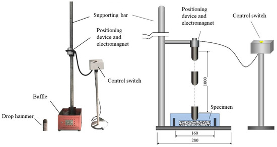
Figure 5.
The improved drop weight test apparatus.
2.4.3. Scanning Electron Microscope (SEM)
An ultra-high resolution scanning electron microscope (SU8010) manufactured by Hitachi, Ltd., Tokyo, Japan, was used to observe the internal microstructure of the concrete. Firstly, concrete fragments were selected as observation specimens from inside the concrete specimen, which should be as flat and small as possible and contain the interfacial transition zone (ITZ) of the concrete. The obtained observation specimens should be immersed in anhydrous ethanol to avoid further hydration of the cement which may affect the accuracy of the test. Prior to the experiment, the observation specimens were vacuum dried for 48 h and then coated with gold. Finally, the specimens were put into the scanning electron microscope for observation.
3. Result and Analysis
3.1. Splitting Tensile Strength
The splitting tensile test results for individual groups were subjected to analysis using the range analysis method, as presented in Table 5. It is clearly demonstrated that, in the orthogonal test, the extreme deviations of WER dosage, RA substitution rate and SF dosage on the splitting tensile strength of RAC were 0.95, 0.73 and 2.09, respectively. Consequently, the primary order of the influences for the factors on the splitting tensile strength of RAC is as follows: SF dosage > WER dosage > RA substitution rate. As the factors of WER dosage and SF dosage exhibit the substantial ranges, they were considered the primary factors, while the RA substitution rate assumes a secondary role in affecting the splitting tensile strength of RAC. In accordance with the principle of selecting the optimal level combination for each factor, it was determined that the optimal level combination is as follows: 4% dosage of WER, 60% substitution rate of RA and 1% dosage of SFs.
Table 5.
Results of the splitting tensile strength and range analysis.
To gain a more intuitive understanding of how various levels of each factor influence the splitting tensile strength of RAC, the data in Table 5 were expressed in the form of effect diagrams, as shown in Figure 6, employing the levels of factors as the horizontal coordinate and the average value of splitting tensile strength at the factor level as the vertical coordinate. From the figure, it becomes evident that the splitting tensile strength of RAC exhibits a positive correlation with the dosage of SFs. In other words, as the dosage of SFs increases, the splitting tensile strength of RAC steadily rises. Specifically, when the SF addition reaches 1%, the splitting tensile strength of RAC reaches a maximum of 5.69 MPa, marking a remarkable 58.1% improvement compared to the specimen without SFs. The SFs incorporated in RAC serve to act as a supportive framework within the concrete matrix, enhancing the structural integrity of RAC [22]. Furthermore, the distribution of SFs mitigates stress concentrations at crack tips, limiting crack propagation and thereby increasing the splitting tensile strength of RAC.

Figure 6.
Effects of influencing factors on the splitting tensile strength.
With respect to the impact of WER dosage, the splitting tensile strength of RAC exhibited an initial rise followed by a decline with the increase in WER dosage. The maximum splitting tensile strength of RAC was achieved at a 4% dosage of WER. The reinforcement effect of WER is primarily due to the interpenetrating spatial network structure formed through the mutual fusion of WER particles and cement gel [23]. This structure aids in stress dispersion and transfer while impeding microcrack growth. Additionally, the interpenetrating spatial network structure offers robust tensile ductility, enhancing toughness and, consequently, splitting tensile strength of RAC. However, when the WER content reached 6%, a notable reduction in the splitting tensile strength of RAC was observed. This decline could be attributed to the high viscosity of the water-borne epoxy resin solution, which introduced air into the slurry in the mixing process and subsequently escalated the porosity within the concrete [15,24]. Furthermore, excessive inclusion of WER in the concrete mixture might result in WER aggregation within the concrete matrix, thereby interrupting the structural continuity and diminishing the splitting tensile strength of the concrete.
Remarkably, the splitting tensile strength of RAC demonstrated a surprising increase with rising RA replacement rate. Specifically, as the RA replacement rate escalated from 0% to 60%, the splitting tensile strength of RAC experienced a notable 17.3% improvement. This phenomenon is mainly attributed to two factors. Firstly, the RA employed in this study underwent processes such as cleaning, drying, and “mechanical strengthening”, resulting in a surface with fewer impurities and greater roughness compared to NA. These enhanced surface characteristics of RA improved the friction between the interface of RA and fresh cement mortar. Secondly, the two-stage mixing process used in this test initially combined water and cement, enveloping the surface of RA with a thin layer of fresh cement mortar. This allows the slurry to infiltrate the attached old mortar and RA, effectively filling their internal pores and enhancing the compactness, thereby contributing to the increased splitting tensile strength of RAC.
3.2. Drop Weight Test
Table 6 presents the results of falling weight tests, including the initial cracking impact number and destructive impact number, as well as the corresponding initial cracking impact energy and destructive impact energy. Remarkably, plain concrete, devoid of RA, WER and SFs, exhibits poor impact resistance. The initial cracking impact number and destructive impact number are both two, indicating that the plain concrete exhibits a pronounced vulnerability to cracking and structural damage when subjected to impact load. It clearly reflects the inherent brittleness of plain concrete. With the incorporation of RA, WER and SFs, the initial cracking impact number and destructive impact number increase. Moreover, the destructive impact number is greater than that of the initial cracking impact, demonstrating that the concrete retains a certain degree of load-bearing capacity after initial cracking. The impact energy, which signifies the energy absorbed by concrete before failure or cracking under impact load, serves as a crucial indicator of impact resistance performance of concrete. The detailed results of impact energy, analyzed via range analysis, are displayed in Table 7. According to the analysis of the effects of WER dosage, RA substitution rate and SF dosage on the impact energy of RAC in the orthogonal test, the primary order of influence for individual factors is given as follows: SF dosage > WER dosage > RA substitution rate. Remarkably, for both the initial cracking impact energy and destructive impact energy, the influence range of SFs exhibits the most significant difference, surpassing that of WER and RA. This underscores the substantial impact of SF incorporation on the impact resistance of RAC. Furthermore, the optimal combination of factors for impact energy is determined as follows: 0% dosage of WER, 60% substitution rate of RA and 1% dosage of SFs.
Table 6.
Results of the drop weight test.
Table 7.
Range analysis results of the impact energy.
Figure 7 and Figure 8 present the effects of various factors on the initial cracking impact energy and destructive impact energy, respectively. It is evident that the impact energy experienced a significant rise with the increasing SF content, particularly for the destructive impact energy. When the SF content increases from 0% to 1.0%, the initial cracking impact energy and destructive impact energy increase by 144.7% and 872.1%, respectively. Prior to the specimen cracking, the SF content improves the toughness of concrete, augmenting the elastic deformation. This slows the progression of plastic deformation and delays crack initiation. Once cracking occurs, the SFs bridging the cracks not only impede expansion and propagation of cracks but also absorb substantial impact energy during the process of pullout and breakage [25]. As showed in Table 6, the disparity between the destructive impact number and initial cracking impact number obviously expands with the increasing SF content, further confirming that the incorporation of SFs significantly enhances the impact resistance of RAC after cracking. In summary, the inclusion of SFs delays crack formation, enhances ductility and improves the overall impact resistance of RAC.

Figure 7.
Effects of influencing factors on the initial cracking impact energy.

Figure 8.
Effects of influencing factors on the destructive impact energy.
As can be seen from Figure 7 and Figure 8, the incorporation of WER exhibits no significant enhancement to the impact resistance of RAC. As WER content increases, the initial cracking impact energy decreases. Regarding the destructive impact energy, an increase in the dosage of WER from 0% to 4% leads to a consistent reduction in the destructive impact energy. However, when the WER dosage reaches 6%, the destructive impact energy of RAC exhibits a minor increment compared to RAC with 4% WER, although it remains lower than the destructive impact energy of RAC with no WER. Specifically, when the WER content reaches 6%, the initial cracking impact energy and destructive impact energy decreased by 42.2% and 26.3%, respectively. WER possesses a low modulus of elasticity, and its addition to RAC in place of cement reduces the rigid support in concrete, rendering it more prone to cracking under impact loading. Furthermore, reactive groups in WER adsorb calcium ions in the slurry, retarding the cement hydration reaction [26]. Consequently, the addition of WER reduces the hydration products in RAC and diminishes internal compactness of concrete. Upon reaching a WER dosage of 6%, the slight rise in the destructive impact energy might be attributed to the synergistic interplay between WER and SFs. WER strengthens the ITZ between SFs and the concrete matrix, consequently elevating the energy demand for SF pullout and enhancing the impact resistance of RAC in the post-cracking stage [27,28]. This synergy between WER and SFs serves to partially compensate for the negative repercussions brought by the incorporation of WER.
The initial cracking impact energy of RAC increases with the increase in RA substitution rate, while the destructive impact energy of RAC first decreases and then increases with the increase in RA substitution rate. At a 60% substitution rate of RA, the initial cracking impact energy and destructive impact energy of RAC specimens increase by 53.2% and 8.4%, respectively, compared to the specimens with 0% RA substitution rate. On the one hand, the rough surface of RA forms a stronger bond with new cement mortar than NA, consequently enhancing the performance of concrete. On the other hand, the water absorption rate of RA is higher than that of NA, so it will absorb more water in the mixing process. During the curing process, the water absorbed by RA is slowly released along with the hydration of cement, which plays the role of “internal curing agent” [29]. As a result, the impact energy of RAC rises with the increasing RA substitution rates.
3.3. SEM
Figure 9a and 9b depict SEM images of the concrete matrix in specimens NC-0-0-0 and RC-0-60-1.0, respectively. These images facilitate an analysis of the impact of RA substitution rate on the performance of RAC. It can be seen that when the recycled coarse aggregate substitution rate is 0%, there are many unevenly distributed pores and even some pits with large sizes and irregular shapes distributed on the surface of the cement stone. In addition, multiple cracks of different lengths and curvatures can be observed on the hardened cement stone surface. These voids and cracks disrupt the continuity and densification of hydration products, rendering the concrete matrix loose in structure. Comparatively, at a 60% RA replacement rate, the number of pores and cracks on the surface of cement stone significantly decreases, with pores notably smaller in size. The continuity of the cementitious material phase is improved, and the overall structure of the concrete appears to be denser. Based on prior research conducted by various scholars [4,5,30], our initial assumption was that the performance of RAC would diminish as the replacement rate of RA increased. However, the findings from our experimental study reveal that, when the replacement rate of RA increased from 0% to 60%, the performance of RAC was not degraded but improved instead. This phenomenon necessitates a comprehensive evaluation, considering factors such as the source and production process of RA, as well as the experimental methodology employed for analysis. Currently, based on the analysis of SEM images, we can make a preliminary inference that the beneficial impact of RA on RAC primarily manifested in enhancing the compactness of the cement matrix. This may be attributed to the higher water absorption rate of RA when compared to NA. During the curing process, the absorbed water in the RA gradually released, promoting more complete hydration reactions. Consequently, this led to increased hydration product formation within the concrete, culminating in a denser cement stone structure.

Figure 9.
SEM images of the microstructures in concrete: (a) without RA; (b) with RA.
In order to investigate the mechanism of WER on interfacial modification, relevant specimens were selected for comparison, as shown in Figure 10. In the specimens without WER, more cracks were evident in the concrete matrix within the ITZ of SFs. This occurrence resulted from the fact that the SF surface exhibited hydrophilicity, causing a higher water–cement ratio in its vicinity, which increased the presence of low-density hydrated calcium silicate gels and pores in the ITZ. As a result, the ITZ between the SFs and the concrete matrix exhibited poor mechanical properties and its structure became loose. Moreover, the gaps in the ITZ between the SFs and the cement stone were larger and the bond was not tight enough. This significantly diminished the performance enhancement effect of SFs on RAC. For the specimen with WER, Figure 10b demonstrates that the number and width of cracks in the concrete in the ITZ were reduced. The incorporation of WER effectively inhibited the generation and expansion of cracks in the concrete matrix and reduced the defects in the ITZ. Additionally, the WER acted as a “bridge” with its polar hydrophilic groups facilitating physicochemical double adsorption, thereby tightly bonding SFs to the cement stone [31]. Consequently, there was no obvious gap between the SFs and cement stone with the incorporation of WER, as shown in Figure 10.

Figure 10.
SEM images of the ITZs between SFs and the concrete matrix: (a) without WER; (b) with WER.
3.4. Life Prediction of Impact
Prior research has demonstrated that, in the drop weight test, the impact numbers (N) conform to a Weibull distribution [32,33]. Consequently, this study employs Weibull distribution theory to analyze the probabilistic statistics regarding the impact numbers of specimen groups and predict their impact lifespan. The probability density function, f(N), and the cumulative distribution function, F(N), can be expressed as:
where N0 denotes the position parameter, Nx denotes the scale parameter and Nx > 0, and γ denotes the shape parameter and γ > 0.
For N0 = 0, the three-parameter Weibull distribution can be simplified to a two-parameter Weibull distribution. Prioritizing safety, reliability and practicality, N0 is treated as being nearly equal to 0 in this study. Consequently, f(N), F(N) and the reliability function R(N), which denotes the survival probability of the specimen for impact times greater than N, are derived, based on the two-parameter Weibull distribution, as shown in the following equations:
Through performing double logarithm transformation on both sides of Equation (8), we obtain the following equation:
Let X = lnN, Y = ln[ln(1/R(N))] and B = γlnNx. We simplify Equation (9) to the following equation:
From Equation (10), it is evident that a linear relationship exists between Y and X. The reliability function R(N) is expressed as:
where t represents the total number of specimens subjected to the drop weight test in each group, and in this study, t is six, and m represents the order number obtained through arranging the impact test results N1 and N2 in increasing order for each group.
Letting X = lnN and Y = ln[ln(1/R(N))] and utilizing Equation (11), the corresponding parameters γ and B, along with the correlation coefficient R2 for each specimen group, were determined through linear regression analysis. Table 8 displays the results of linear regression for each specimen group. Notably, all the fitted correlation coefficient R2 values for different specimen groups exceed 0.90, with the minimum value of 0.904. This implies a significant linear correlation between ln[ln(1/R(N))] and lnN, affirming the superior ability of the two-parameter Weibull distribution to characterize the probability distribution of impact numbers for individual specimen groups.
Table 8.
Linear regression results of the parameters for Weibull distribution.
The relationship between the failure probability function Pf(N) and the reliability function R(N) is elucidated in Equation (12). According to Equations (8)–(10) and (12), the expressions for the impact numbers of specimens under different failure probabilities are derived, as shown in Equation (13).
Equation (13) establishes the relationship between the failure probability and impact life (impact number). Utilizing this equation and the parameters derived via linear regression, the impact resistance numbers of specimens at different failure probabilities (0.1, 0.15, 0.3) are obtained, as presented in Table 9.
Table 9.
Prediction results of the impact resistance numbers under different failure probabilities.
Based on the predicted values of N1 and N2 for each group of specimens outlined in Table 9, the trends in the natural logarithms, lnN1 and lnN2, of the estimated impact life for each group of specimens at various failure probabilities are plotted as shown in Figure 11. Figure 11 illustrates that the trends of lnN1 and lnN2 for different groups of specimens, under varying failure probabilities, align closely with the corresponding measured values. Moreover, the specimen RC-0-60-1.0 exhibited the best performance in terms of the impact resistance across the range of failure probabilities. The incorporation of SFs has the most significant impact on the impact life. All the specimens with 1.0% SF incorporation exhibited a marked enhancement in lnN1 and lnN2 values, demonstrating excellent impact resistance. Furthermore, the additions of WER and RA perform a moderate improvement in the impact life of the concrete specimens. In addition, as the probability of failure increases, the predicted values of lnN1 and lnN2 for each group of specimens also increase, consistent with the inherent characteristics of concrete materials and their structural behaviors.

Figure 11.
Line diagrams of the impact life: (a) lnN1 and (b) lnN2 of the specimens under different failure probabilities.
4. Conclusions
Based on the experimental results and analysis in this study, the following conclusions can be drawn:
- (1)
- In the experiment, we obtained experimental results that were contrary to expectations. As the substitution rate of RA increased, the split tensile strength and impact resistance of RAC were improved. At a 60% RA substitution rate, the splitting tensile strength, initial cracking impact energy and destructive impact energy of RAC increased by 17.3%, 53.2% and 8.4%, respectively. This phenomenon might be attributed to the inherent “internal curing” effect of RA, leading to an enhancement in the compactness of the concrete matrix, as it was distinctly observable in SEM images.
- (2)
- Surprisingly, the incorporation of WER significantly improved the splitting tensile strength of RAC but had no significant enhancement effect on the impact resistance. Therefore, in the orthogonal test of this study, the optimum levels of WER dosage for splitting tensile strength and impact energy were 4% and 0%, respectively. Owing to the constraints inherent in the orthogonal experiment, our capacity to discern the detrimental impact of WER on the impact resistance of RAC was confined to macroscopic data. Consequently, we were unable to ascertain whether this effect arose from an interaction with other factors, such as the replacement rate of RA.
- (3)
- The addition of SFs emerged as the paramount influencing factor for both splitting tensile strength and impact resistance of RAC. With increasing SF content, the performance of RAC, especially its impact resistance, was improved significantly. Specifically, both the initial cracking impact energy and destructive impact energy reached their peaks at the 1.0% SF dosage, marking increases of 144.7% and 872.1%, respectively, compared to the specimens without SFs.
- (4)
- Through analyzing the SEM images, it can be concluded that WER exhibited the ability to enhance the ITZs of SFs, improving bonds between SFs and the concrete matrix. The synergistic effect between WER and SFs significantly enhanced the ability of RAC to withstand impact loads after initial cracking.
- (5)
- The two-parameter Weibull distribution effectively characterized the distribution characteristics of the impact times for polymer-modified steel fiber-reinforced recycled aggregate concrete specimens. Across varying failure probabilities, the predicted values of impact life for each specimen group consistently mirrored the corresponding measured values. The positive correlation between the predicted values of the impact life and the probability of failure could provide guidance for structural design under various failure probabilities.
Author Contributions
Conceptualization, D.X.; Methodology, D.X. and K.R.; Software, K.R.; Validation, Y.W. and K.R.; Formal analysis, Y.W. and K.R.; Investigation, K.R.; Resources, D.X.; Data curation, Y.W. and K.R.; Writing—original draft preparation, Y.W. and K.R.; Writing—review and editing, D.X.; Visualization, Y.W. and K.R.; Supervision, D.X.; Project administration, D.X.; Funding acquisition, D.X. All authors have read and agreed to the published version of the manuscript.
Funding
This research was funded by National Natural Science Foundation of China (Grant No. 51108164).
Data Availability Statement
The data presented in this study are available on request from the corresponding author. The data are not publicly available due to privacy.
Conflicts of Interest
The authors declare no conflict of interest.
References
- Estanqueiro, B.; Silvestre, J.D.; de Brito, J.; Pinheiro, M.D. Environmental life cycle assessment of coarse natural and recycled aggregates for concrete. Eur. J. Environ. Civ. Eng. 2018, 22, 429–449. [Google Scholar] [CrossRef]
- Kadawo, A.; Sadagopan, M.; During, O.; Bolton, K.; Nagy, A. Combination of LCA and circularity index for assessment of environmental impact of recycled aggregate concrete. J. Sustain. Cem.-Based Mater. 2022, 12, 1–12. [Google Scholar] [CrossRef]
- Kim, J. Influence of quality of recycled aggregates on the mechanical properties of recycled aggregate concretes: An overview. Constr. Build. Mater. 2022, 328, 127071. [Google Scholar] [CrossRef]
- Lu, Y.; Chen, X.; Teng, X.; Zhang, S. Impact behavior of recycled aggregate concrete based on split Hopkinson pressure bar tests. Adv. Mater. Sci. Eng. 2013, 2013, 391957. [Google Scholar] [CrossRef]
- Rao, M.C.; Bhattacharyya, S.K.; Barai, S.V. Behaviour of recycled aggregate concrete under drop weight impact load. Constr. Build. Mater. 2011, 25, 69–80. [Google Scholar]
- Wang, X.; Cheng, F.; Wang, Y.; Zhang, X.; Niu, H. Impact properties of recycled aggregate concrete with nanosilica modification. Adv. Civ. Eng. 2020, 2020, 8878368. [Google Scholar] [CrossRef]
- Zhang, T.; Wu, B.; Kong, X.; Fu, Y. Investigation of impact resistance of high-performance polypropylene fiber-reinforced recycled aggregate concrete. Crystals 2022, 12, 669. [Google Scholar] [CrossRef]
- Xia, D.; Xie, S.; Fu, M.; Zhu, F. Effects of maximum particle size of coarse aggregates and steel fiber contents on the mechanical properties and impact resistance of recycled aggregate concrete. Adv. Struct. Eng. 2021, 24, 3085–3098. [Google Scholar] [CrossRef]
- Omidinasab, F.; Moazami Goodarzi, S.; Sahraei Moghadam, A. Characterization and optimization of mechanical and impact properties of steel fiber reinforced recycled concrete. Int. J. Civ. Eng. 2022, 20, 41–55. [Google Scholar] [CrossRef]
- Jahandari, S.; Mohammadi, M.; Rahmani, A.; Abolhasani, M.; Miraki, H.; Mohammadifar, L.; Kazemi, M.; Saberian, M.; Rashidi, M. Mechanical properties of recycled aggregate concretes containing silica fume and steel fibres. Materials 2021, 14, 7065. [Google Scholar] [CrossRef]
- Abu-Lebdeh, T.; Hamoush, S.; Heard, W.; Zornig, B. Effect of matrix strength on pullout behavior of steel fiber reinforced very-high strength concrete composites. Constr. Build. Mater. 2011, 25, 39–46. [Google Scholar] [CrossRef]
- Schleiting, M.; Klier, K.; Wiemer, N.; Wetzel, A.; Zarges, J.-C.; Heim, H.-P.; Middendorf, B. Fibre pullout behaviour of fibre-reinforced UHPC with TPE-coated fibres. Constr. Build. Mater. 2023, 376, 131043. [Google Scholar] [CrossRef]
- Saludung, A.; Azeyanagi, T.; Ogawa, Y.; Kawai, K. Alkali leaching and mechanical performance of epoxy resin-reinforced geopolymer composite. Mater. Lett. 2021, 304, 130663. [Google Scholar] [CrossRef]
- Moodi, F.; Kashi, A.; Ramezanianpour, A.A.; Pourebrahimi, M. Investigation on mechanical and durability properties of polymer and latex-modified concretes. Constr. Build. Mater. 2018, 191, 145–154. [Google Scholar] [CrossRef]
- Pang, B.; Zhang, Y.; Liu, G. Study on the effect of waterborne epoxy resins on the performance and microstructure of cement paste. Constr. Build. Mater. 2018, 167, 831–845. [Google Scholar] [CrossRef]
- Pang, B.; Jin, Z.; Zhang, Y.; Xu, L.; Li, M.; Wang, C.; Zhang, Y.; Yang, Y.; Zhao, P.; Bi, J.; et al. Ultraductile waterborne epoxy-concrete composite repair material: Epoxy-fiber synergistic effect on flexural and tensile performance. Cem. Concr. Compos. 2022, 129, 104463. [Google Scholar] [CrossRef]
- Farooq, M.; Banthia, N. Strain-hardening fiber reinforced polymer concrete with a low carbon footprint. Constr. Build. Mater. 2022, 314, 125705. [Google Scholar] [CrossRef]
- JGJ/T 240-2011; Technical Specification for Application of Recycled Aggregate. China Architecture & Building Press: Beijing, China, 2011.
- JGJ/T 221-2010; Technical Specification for Application of Fiber Reinforced Concrete. China Architecture & Building Press: Beijing, China, 2010.
- GB/T 50081-2019; Standard for Test Methods of Concrete Physical and Mechanical Properties. China Architecture & Building Press: Beijing, China, 2019.
- CECS 13:2009; Standard Test Methods for Fiber Reinforced Concrete. Beijing China Planning Publishing House: Beijing, China, 2009.
- Gao, D.; Guo, Y.; Pang, Y.; Chen, G.; Shi, M.; Ding, C.; Liu, D. Analysis and prediction of the compressive and splitting tensile performances for the novel multiple hooked-end steel fiber reinforced concrete. Struct. Concr. 2023, 24, 1452–1470. [Google Scholar] [CrossRef]
- Colangelo, F.; Roviello, G.; Ricciotti, L.; Ferone, C.; Cioffi, R. Preparation and characterization of new geopolymer-epoxy resin hybrid mortars. Materials 2013, 6, 2989–3006. [Google Scholar] [CrossRef]
- Daskiran, E.G.; Daskiran, M.M.; Gencoglu, M. Effect of polymer addition on air void content of fine grained concretes used in TRCC. Comput. Concr. 2017, 20, 165–176. [Google Scholar]
- Gao, Y.T.; Wang, B.; Xu, Q.; Liu, C.J.; Hui, D.V.; Yuan, W.G.; Tang, H.F.; Zhao, J.J. Experimental study on recycled steel fiber-reinforced concrete under repeated impact. Rev. Adv. Mater. Sci. 2023, 62, 20220312. [Google Scholar] [CrossRef]
- Wang, M.; Wang, R.M.; Yao, H.; Farhan, S.; Zheng, S.R.; Wang, Z.J.; Du, C.C.; Jiang, H. Research on the mechanism of polymer latex modified cement. Constr. Build. Mater. 2016, 111, 710–718. [Google Scholar] [CrossRef]
- Li, G.Y.; Zhao, X.H.; Rong, C.Q.; Wang, Z. Properties of polymer modified steel fiber-reinforced cement concretes. Constr. Build. Mater. 2010, 24, 1201–1206. [Google Scholar] [CrossRef]
- Esmaeili, J.; Andalibi, K.; Gencel, O.; Maleki, F.K.; Maleki, V.A. Pull-out and bond-slip performance of steel fibers with various ends shapes embedded in polymer-modified concrete. Constr. Build. Mater. 2021, 271, 121531. [Google Scholar] [CrossRef]
- Djerbi, A. Effect of recycled coarse aggregate on the new interfacial transition zone concrete. Constr. Build. Mater. 2018, 190, 1023–1033. [Google Scholar] [CrossRef]
- Liu, B.; Feng, C.; Deng, Z.H. Shear behavior of three types of recycled aggregate concrete. Constr. Build. Mater. 2019, 217, 557–572. [Google Scholar] [CrossRef]
- Zhao, C.H.; Yi, Z.J.; Wu, W.W.; Zhu, Z.W.; Peng, Y.; Liu, J. Experimental study on the mechanical properties and durability of high-content hybrid fiber-polymer concrete. Materials 2021, 14, 6234. [Google Scholar] [CrossRef]
- Gao, D.Y.; Zhang, L.J.; Nokken, M.; Zhao, J. Mixture proportion design method of steel fiber reinforced recycled coarse aggregate concrete. Materials 2019, 12, 375. [Google Scholar] [CrossRef]
- Han, J.H.; Liu, Z.Y.; Zhang, C.F. Experimental study on impact resistance of steel-fiber-reinforced two-grade aggregate concrete. Constr. Build. Mater. 2023, 373, 130901. [Google Scholar] [CrossRef]
Disclaimer/Publisher’s Note: The statements, opinions and data contained in all publications are solely those of the individual author(s) and contributor(s) and not of MDPI and/or the editor(s). MDPI and/or the editor(s) disclaim responsibility for any injury to people or property resulting from any ideas, methods, instructions or products referred to in the content. |
© 2023 by the authors. Licensee MDPI, Basel, Switzerland. This article is an open access article distributed under the terms and conditions of the Creative Commons Attribution (CC BY) license (https://creativecommons.org/licenses/by/4.0/).