Abstract
This study focuses on the shear serviceability of simple and continuous reinforced concrete deep beams. The test results of 81 simple deep beams (i.e., simply supported single-span deep beams) and 29 continuous deep beams, for which their diagonal tension cracking loads were reported, were collected from existing studies. On this basis, the diagonal tension cracking mechanism is discussed, and four existing models for diagonal tension cracking are evaluated. The evaluation results show the existing models fail to accurately reflect the influences of the main design parameters (including the shear span-to-effective depth ratio and main tensile reinforcement ratio) on the diagonal tension cracking strength. Therefore, a new equation for the diagonal tension cracking strength for simple and continuous deep beams is proposed. The proposed equation is verified to be superior to the existing models, showing an average value and a coefficient of variation for tested-to-predicted diagonal tension cracking strength ratios of 1.02 and 0.21, respectively. On the other hand, a probabilistic analysis is conducted to evaluate the diagonal tension cracking risk under service load, showing that 35% of deep beams exhibited a diagonal tension cracking load that is less than the service load, which indicated that diagonal cracks easily occur in RC deep beams under service loads.
1. Introduction
Reinforced concrete (RC) simple deep beams (SDBs) and continuous deep beams (CDBs) are widely used for bridge cap beams, building transfer girders, and pile supported foundations. The shear strength of RC deep beams has been extensively studied by authors [1,2,3] and other researchers [4,5,6,7,8,9,10,11,12,13,14,15,16]. The strut-and-tie mechanism of simple and continuous deep beams was identified in experimental studies [4,6], and shear strength evaluations were carried out based on strut-and-tie or truss models [1,2,3,5,7,8,9,10,11,12,13,14,15,16]. On the other hand, the ultimate shear serviceability of deep beams is also of interest to researchers and engineers.
Unlike the ultimate shear strength, studies on the serviceability (such as diagonal tension cracking load and crack width under service load) of RC deep beams are limited. Due to the tied-arch mechanism, a deep beam can still carry considerable additional load after diagonal cracking. Furthermore, because of the ratio of diagonal tension cracking strength to ultimate shear strength decreases with the decrease in the shear span-to-effective depth ratio [17], the risk of diagonal tension cracking at service loads for deep beams is higher compared to that of slender beams. Birrcher [18] reported that diagonal cracks had been observed in several RC bent caps in service and two had to be retrofitted in a costly manner. Existing models [18,19,20,21] to calculate the diagonal tension cracking load are developed on the basis of limited test results. Different influencing parameters are considered by these models, which results in inconsistent predictions even in the same design condition.
In the present study, a state-of-the-art test database for diagonal tension cracking load of 110 simple and continuous deep beams is collected to evaluate the existing diagonal tension cracking models, and an improved equation for diagonal tension cracking load is proposed. Moreover, a probabilistic analysis is conducted to evaluate the diagonal tension cracking risk under service loads.
2. Database for Diagonal Tension Cracking Strength Evaluation
In order to study the diagonal tension cracking strength of SDBs and CDBs, 81 SDBs [4,18,22,23,24,25] and 29 CDBs [4,26,27,28] were collected and evaluated. Table 1 presents the database for the evaluation. The following criteria are considered in both the SDBs and CDBs: (1) the shear span-to-effective depth ratio a/d ≤ 2.0; (2) dimensions of loading and supporting plates are reported; (3) specimens are reported to fail in shear, and the reported ultimate load is less than 1.1 times of the prediction of by the strut-and-tie model (STM) according to ACI 318-14 when main tensile reinforcements are yielded [2,15]. The last criterion is to ensure that the collected specimens failed in shear tests because the diagonal tension cracking strength and subsequent diagonal cracks are not critical to flexural failure-controlled specimens. The main longitudinal reinforcement for all the beams in the database are deformed steel bars, while deformed or round steel bars were used for distributed web reinforcements.

Table 1.
Database for diagonal tension cracking strength evaluation of simple and continuous deep beams.
Figure 1 presents the variance of the dimensionless diagonal tension cracking strength according to main design parameters, including the shear span-to-effective depth ratio a/d, the concrete cylinder compressive strength fc′, main tensile reinforcement ratio ρl, ratio of distributed reinforcement passing through a diagonal strut ρT, and effective depth d. It should be noted that a is the length of the shear span where shear failure occurs. For CDBs in the database, the shear failure is concentrated in the inner shear span. Effective depth d is the distance from the bottom main longitudinal reinforcement centroid to the top of the beam cross section for both simple and continuous deep beams. The main tensile reinforcement ratio ρl of SDBs considers only main longitudinal reinforcement at beam bottom, while ρl of CDBs considers main longitudinal reinforcements at both beam top and bottom. The reason is that both the top and bottom reinforcements in tension form truss systems with diagonal struts in CDBs to carry external loads, as shown in Figure 2. Ratio ρT equals ρhsinθ + ρvcosθ, where ρh and ρv are the horizontal and vertical web reinforcement ratios, respectively, and θ is the inclination of the diagonal strut. The ratios ρh and ρv equal Ash1/(shb) and Asv1/(svb), respectively, where Ash1 and Asv1 are areas of one layer of horizontal and vertical web reinforcement, respectively, and sh and sv are spacings of horizontal and vertical web reinforcement, respectively. The strut inclination θ is determined according to [2].
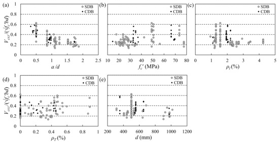
Figure 1.
Relationship between dimensionless diagonal tension cracking strength Vcr,t/(√fc′bd) and design parameters. (a) Shear span-to-effective depth ratio a/d; (b) concrete compressive strength fc′; (c) main tensile reinforcement ratio ρl; (d) distributed reinforcement ratio ρT; (e) effective depth d.
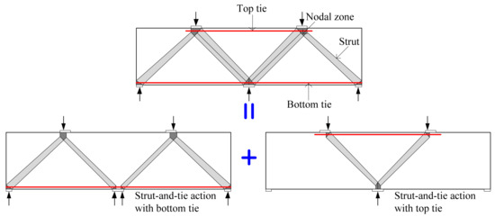
Figure 2.
Combination of strut-and-tie actions with bottom and top ties in CDBs (adapted from Rogowsky [29]).
From Figure 1, it can be seen that the diagonal tension cracking strength of the CDBs shows similar tendency with that of the SDBs. The diagonal tension cracking strength of both SDBs and CDBs increases significantly with the increase in fc′ or decrease in a/d. On the other hand, the effect of distributed web reinforcement on the cracking strength is not significant. For the effect of ρl and d, further analysis is needed below, although the diagonal tension cracking strength shows slight downward overall trends with increases in ρl and d.
3. Diagonal Tension Cracking Strength Modeling and Evaluation
The diagonal tension cracking strength of deep beams can be evaluated by using existing models, such as the splitting model, empirical model, and flexural-shear cracking model. Figure 3 shows the STM based splitting model. In a bottle-shaped strut, lateral spreading of compression force generates tensile stresses perpendicular to the strut and initiates longitudinal splitting cracks near the ends of the strut. On the basis of the splitting model, Foster [19] assumed uniformly distributed transverse stress through the bursting region to obtain the splitting stress (Equation (1)), while Sahoo et al. [20] considered an idealized triangular stress distribution (Equation (2)):
where Vcr is the diagonal tension cracking strength predicted by models; ls′ is the length of bursting zone in the strut defined by Foster [20], and it is slightly shorter than the strut length ls (refer to Figure 3).
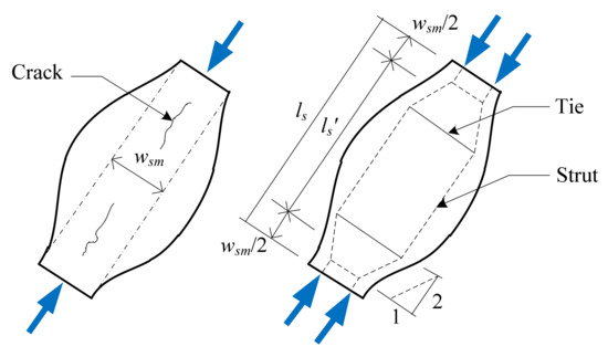
Figure 3.
Splitting cracks of a bottle-shaped strut.
Birrcher [18] proposed an empirical equation (Equation (3)) for the cracking strength of a strut as a function of a/d, without consideration of the diagonal tension cracking mechanism. Moreover, Equation (3) was fitted according to test results of SDBs only, without considering CDBs.
Kim and White [21] proposed a flexural-shear cracking model on the basis of flexural-shear cracks caused by local stress concentration after flexural cracking initiation. They considered that the local stress concentration is associated with the bond strength between concrete and longitudinal bars and the development of arch action in the shear span of the beam. Because Equation (4) is derived from simple beams, it is not applicable to CDBs.
Figure 4 compares the test results and predictions of Equations (1)–(4). Although different transverse stress distributions are assumed by Foster [19] and Sahoo et al. [20], the splitting models in Equations (1) and (2) overestimate the test results of SDBs and CDBs. Their tested-to-predicted diagonal tension cracking strength ratios Vcr,t/Vcr present average values of 0.43 and 0.67, respectively, and coefficients of variation (COVs) of 0.38 and 0.31, respectively. On the other hand, Birrcher’s empirical model [18] (Equation (3)) and Kim’s flexural-shear cracking model [21] (Equation (4)) predict the test results relatively well, showing lower values of COV (0.25 and 0.27, respectively). However, the inaccuracy of the predictions is still significant in deep beams with a/d ≥ 1.0, as shown in Figure 4.
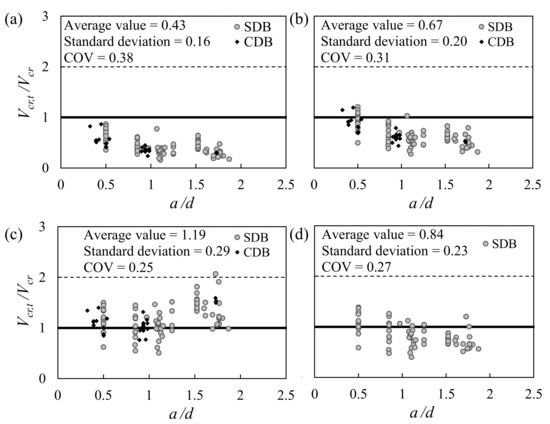
Figure 4.
Comparison between test results and predictions of existing diagonal tension cracking models. (a) Foster’s model [19]; (b) Sahoo’s model [20]; (c) Birrcher’s model [18]; (d) Kim’s model [21].
Considering ls′sinθ = 0.8d in Equation (1) and lssinθ = 0.9d in Equation (2), the splitting models (i.e., Equations (1) and (2)) can be defined as a function of . As shown in Figure 4, unlike Equations (3) and (4) showing better predictions, the effect of a/d on the diagonal tension cracking strength is not considered in the splitting models.
Figure 5 compares Equation (3) which neglects the main reinforcement, with Equation (4) which addresses the bottom main reinforcement of SDBs. The prediction by Equation (3) shows a increasing trend of Vcr,t/Vcr with an increase in main tensile reinforcement ratio ρl, while the prediction by Equation (4) presents a more consistent trend. It indicates that the diagonal tension cracking strength is affected by the main tensile reinforcement. In Equation (4), Kim’s model [21] based on flexural-shear cracking mechanism identifies the factors that affect the diagonal tension cracking load. However, the model considers some assumptions (such as the arch-like variation of internal moment arm length) only for simple beams. Furthermore, the majority of the specimens for model calibration are slender beams, which deteriorates model accuracy in deep beams.
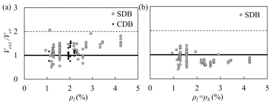
Figure 5.
Diagonal tension cracking strength according to longitudinal bar ratio. (a) Birrcher’s model [18]; (b) Kim’s model [21].
In this study, according to the identified design parameters, an equation with unknown constants (k1, k2, and k3) was proposed: Vcr = k1(a/d)k2ρlk3√fc′bd. The constants are determined by regression analysis of the 110 existing deep beam test results in Table 1. The proposed diagonal tension cracking equation is defined as Equation (5).
Figure 6 compares the test results with the predictions of the proposed model. The proposed method predicted the diagonal tension cracking strength of the test specimens with reasonable precision. The average value and COV of tested-to-predicted diagonal tension cracking strength ratios Vcr,t/Vcr are 1.02 and 0.21, respectively. In addition, the ratios present no significant upward or downward trend with the variation of main design parameters, including the shear span-to-effective depth ratio a/d, the concrete cylinder compressive strength fc′, main tensile reinforcement ratio ρl, ratio of distributed reinforcement passing through a diagonal strut ρT, and effective depth d. Therefore, compared with existing models, the proposed model can better predict diagonal tension cracking strengths and can accurately reflect the influence of main design parameters on the diagonal tension cracking strength. It should be noted that the diagonal tension cracking strength of deep beams does not show a significant size effect within the scope of this study. To properly evaluate the impact of size effect on the diagonal tension cracking of deep beams, larger-scale experiments and more theoretical studies are still needed.
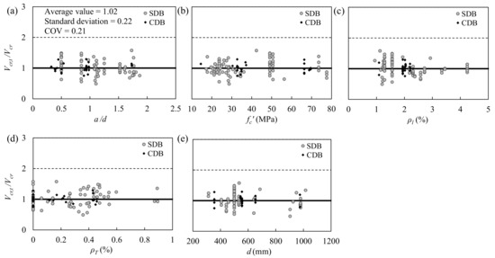
Figure 6.
Tested-to-predicted diagonal tension cracking strength ratios Vcr,t/Vcr by proposed model according to main design parameters. (a) Shear span-to-effective depth ratio a/d; (b) concrete compressive strength fc′; (c) main tensile reinforcement ratio ρl; (d) distributed reinforcement ratio ρT; (e) effective depth d.
4. Diagonal Tension Cracking Risk under Service Load
Birrcher [18] proposed an approach to estimate the service load of AASHTO LRFD as a function of the capacity of test specimens. According to this approach, the service load of ACI 318-14 [30] is calculated as 34% of the test results. The calculation details are presented in Appendix A. This value is regarded as a general representation of the service load on a deep beam [18]. It should be noted that the authors adopt ACI 318-14 instead of ACI 318-19 [31] because ACI 318-19 is the latest version of the ACI design code, and there are still very few deep beams designed according to it in practical engineering. In order to more reasonably estimate the diagonal tension cracking risk of deep beams under service load in practice, the STM in ACI 318-14 was adopted, which has not been substantially changed since it was first introduced into the ACI design code in 2002.
Figure 7 shows the ratios of the tested diagonal tension cracking strength to ultimate shear strength (Vcr,t/Vu,t) of the deep beam specimens in the database. The ratios range from about 0.2 to 0.8. Comparing with the prediction of service load level (=0.34Vt), 35% of deep beams exhibited the diagonal tension cracking load less than the service load (i.e., Vcr/Vt < 34%). This result indicates that diagonal cracks can easily occurr in RC deep beams under service load. Thus, the minimum web reinforcement provision (i.e., vertical and horizontal web reinforcement ratios shall be at least 0.25%) specified in Section 9.9.3.1 of ACI 318-14 [29] should be strictly followed. It was experimentally verified to be efficient for controlling the maximum diagonal crack width by Birrcher [18].
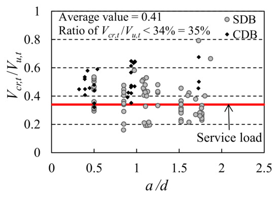
Figure 7.
Ratios of diagonal cracking-to-ultimate shear strength according to shear span-to-effective depth ratio a/d.
5. Summary and Conclusions
In the present study, the diagonal tension cracking strength and risk of simple and continuous deep beams under service load were analyzed. To evaluate the validity of existing diagonal tension cracking models, their predictions are compared to existing deep beam test results collected by the authors. Moreover, a new model is proposed. The principal results are summarized as follows:
- The evaluation of the four existing diagonal tension cracking model based on the 110 collected deep beam tests shows that the models fail to accurately reflect the influences of main design parameters on the diagonal tension cracking strength. On the other hand, design parameters a/d, and ρl are identified as the influential parameters of the diagonal tension cracking strength.
- Using the design parameters, a new equation is proposed to better predict the diagonal tension cracking strength of deep beams including SDBs and CDBs. The average value and COV of tested-to-predicted diagonal tension cracking strength ratios are 1.02 and 0.21, respectively. Moreover, the proposed model is verified to accurately reflect the influence of main design parameters on the diagonal tension cracking strength of RC SDBs and CDBs.
- Under service load, diagonal cracks occur easily in RC deep beams. Thus, the minimum transverse reinforcement requirement prescribed in the ACI 318 design code should be strictly satisfied.
Author Contributions
Conceptualization, H.C. and W.-J.Y.; methodology, H.C.; software, H.C.; validation, H.C. and K.-J.Z.; formal analysis, H.C.; investigation, H.C.; data curation, K.-J.Z.; writing—original draft preparation, H.C.; writing—review and editing, W.-J.Y.; visualization, H.C.; supervision, W.-J.Y.; project administration, W.-J.Y.; funding acquisition, H.C. and W.-J.Y. All authors have read and agreed to the published version of the manuscript.
Funding
This research was funded by the National Natural Science Foundation of China, grant number 52008161 and 51878260, and China Postdoctoral Science Foundation, grant number 2020M682557 and 2021T140196. The APC was funded by 2021T140196.
Institutional Review Board Statement
Not applicable.
Informed Consent Statement
Not applicable.
Data Availability Statement
The data used to support the findings of this study are included within the article.
Conflicts of Interest
The authors declare no conflict of interest.
Nomenclature
| a | shear span length |
| a/d | shear span-to-effective depth ratio |
| b | beam width |
| d | distance from top face to the centroid of bottom bars of beam cross section |
| fc′ | concrete cylinder compressive strength |
| h | beam height |
| ls | strut length |
| ls′ | length of bursting zone in a strut |
| Vcr | diagonal tension cracking strength predicted by models |
| Vcr,t | diagonal tension cracking strength obtained by test |
| Vu,t | ultimate shear strength obtained by test |
| wsm | average strut width |
| θ | diagonal strut angle |
| ρb, ρt | bottom and top main tensile reinforcement ratios |
| ρh, ρv | ratios of horizontal and vertical web reinforcement, respectively |
| ρl | main tensile reinforcement ratio |
| ρT | ratio of distributed web reinforcement passing through a diagonal strut |
Appendix A. Estimation of Service Load Based on Experimental Capacity
According to the approach by Birrcher [18], the ACI 318-14 [30] strength equation can be re-written such that the ratio of the strength reduction factor (ϕ) to the load factor (φ) is approximately equal to the ratio of the service load to the nominal capacity.
ϕ Nominal Capacity ≈ φ Service Load
The strength reduction factor (ϕ) for elements in a strut-and-tie model is defined as 0.75 in ACI 318-14. The load factor (φ) is defined as a function of the load case and load distribution. Considering the following two assumptions, φ equals to 1.3 approximately:
- (1)
- For design loads, the load combination is considered as 1.2 DL + 1.6 LL, where DL is the dead load and LL is the live load.
- (2)
- Under service load, 75% and 25% of service load are contributed by DL and LL, respectively.
According to the strut-and-tie analysis results of the simple and continuous deep beams in [2], the experimental capacity is 1.70 times greater than the nominal capacity. Thus, the service load is calculated as 34% of the peak strength in the test results.
References
- Chen, H.; Yi, W.-J.; Hwang, H.-J. Cracking strut-and-tie model for shear strength evaluation of reinforced concrete deep beams. Eng. Struct. 2018, 163, 396–408. [Google Scholar] [CrossRef]
- Chen, H.; Yi, W.-J.; Ma, Z.J.; Hwang, H.-J. Shear strength of reinforced concrete simple and continuous deep beams. ACI Struct. J. 2019, 116, 31–40. [Google Scholar] [CrossRef]
- Chen, H.; Yi, W.-J.; Ma, Z.J. Shear-Transfer Mechanisms and Strength Modeling of RC Continuous Deep Beams. J. Struct. Eng. 2020, 146, 04020240. [Google Scholar] [CrossRef]
- Rogowsky, D.M.; MacGregor, J.G.; Ong, S.Y. Tests of reinforced concrete deep beams. ACI J. 1986, 83, 614–623. [Google Scholar]
- Rogowsky, D.; MacGregor, J. Design of reinforced concrete deep beams. Concr. Int. 1986, 8, 49–58. [Google Scholar]
- Tan, K.; Lu, H. Shear behavior of large reinforced concrete deep beams and code comparisons. ACI Struct. J. 1999, 96, 836–846. [Google Scholar]
- Hwang, S.-J.; Lu, W.-Y.; Lee, H.-J. Shear strength prediction for deep beams. ACI Struct. J. 2000, 97, 367–376. [Google Scholar]
- Matamoros, A.B.; Wong, K. Design of simply supported deep beams using strut and tie models. ACI Struct. J. 2003, 100, 704–712. [Google Scholar]
- Russo, G.; Venir, R.; Pauletta, M. Reinforced concrete deep beams-shear strength model and design formula. ACI Struct. J. 2005, 102, 429–437. [Google Scholar]
- Zhang, N.; Tan, K.-H. Direct strut-and-tie model for single span and continuous deep beams. Eng. Struct. 2007, 29, 2987–3001. [Google Scholar] [CrossRef]
- Brown, M.D.; Bayrak, O. Design of deep beams using strut-and-tie models-Part I: Evaluating US provisions. ACI Struct. J. 2008, 105, 395–404. [Google Scholar]
- Brown, M.D.; Bayrak, O. Design of deep beams using strut-and-tie models-Part II: Design recommendations. ACI Struct. J. 2008, 105, 405–413. [Google Scholar]
- Yang, K.; Ashour, A. Load capacity of reinforced concrete continuous deep beams. J. Struct. Eng. 2008, 134, 919–929. [Google Scholar] [CrossRef]
- Yang, K.H.; Ashour, A.F. Strut-and-Tie Model Based on Crack Band Theory for Deep Beams. J. Struct. Eng. 2011, 137, 1030–1038. [Google Scholar] [CrossRef] [Green Version]
- Reineck, K.-H.; Todisco, L. Database of Shear Tests for Non-slender Reinforced Concrete Beams without Stirrups. ACI Struct. J. 2014, 111, 1363–1372. [Google Scholar] [CrossRef]
- Todisco, L.; Reineck, K.H.; Bayrak, O. Database with Shear Tests on Non-Slender Reinforced Concrete Beams with Vertical Stirrups. ACI Struct. J. 2015, 112, 761–769. [Google Scholar] [CrossRef]
- Hong, S.-G.; Ha, T. Effective capacity of diagonal strut for shear strength of reinforced concrete beams without shear reinforcement. ACI Struct. J. 2012, 109, 139–148. [Google Scholar]
- Birrcher, D.B. Design of Reinforced Concrete Deep Beams for Strength and Serviceability; The University of Texas at Austin: Austin, TX, USA, 2009. [Google Scholar]
- Foster, S.J. Design of non-flexural members for shear. Cem. Concr. Compos. 1998, 20, 465–475. [Google Scholar] [CrossRef]
- Sahoo, D.K.; Singh, B.; Bhargava, P. Minimum reinforcement for preventing splitting failure in bottle-shaped struts. ACI Struct. J. 2011, 108, 206–216. [Google Scholar]
- Kim, W.; White, R.N. Initiation of shear cracking in reinforced concrete beams with no web reinforcement. ACI Struct. J. 1991, 88, 301–308. [Google Scholar]
- Zhang, N.; Tan, K.H. Size effect in RC deep beams: Experimental investigation and STM verification. Eng. Struct. 2007, 29, 3241–3254. [Google Scholar] [CrossRef]
- Oh, J.-K.; Shin, S.-W. Shear strength of reinforced high-strength concrete deep beams. ACI Struct. J. 2001, 98, 164–173. [Google Scholar]
- Moody, K.; Viest, I.; Elstner, R.; Hognestad, E. Shear strength of reinforced concrete beams Part 1-Tests of simple beams. ACI 1954, 51, 317–332. [Google Scholar]
- Brown, M.D.; Sankovich, C.L.; Bayrak, O.; Jirsa, J.O.; Breen, J.E.; Wood, S.L. Design for Shear in Reinforced Concrete Using Strut-and-Tie Models; Report No 0-4371-2; Center for Transportation Research, the University of Texas at Austin: Austin, TX, USA, 2006. [Google Scholar]
- Yang, K.-H.; Chung, H.-S.; Ashour, A.F. Influence of shear reinforcement on reinforced concrete continuous deep beams. ACI Struct. J. 2007, 104, 420–429. [Google Scholar]
- Yang, K.H.; Chung, H.S.; Ashour, A.F. Influence of section depth on the structural behaviour of reinforced concrete continuous deep beams. Mag. Concr. Res. 2007, 59, 575–586. [Google Scholar] [CrossRef] [Green Version]
- Tan, K.-H.; Kong, F.-K.; Teng, S.; Weng, L.-W. Effect of web reinforcement on high-strength concrete deep beams. ACI Struct. J. 1997, 94, 572–582. [Google Scholar]
- Rogowsky, D.M. Continuous deep beams. In Reinforced Concrete Deep Beams; Kong, F.K., Ed.; Blackie: Glasgow, UK, 1990. [Google Scholar]
- ACI 318 Committee. Building Code Requirements for Structural Concrete (ACI 318-14): Commentary on Building Code Requirements for Structural Concrete (ACI 318R-14); American Concrete Institute: Farmington Hills, MI, USA, 2014; p. 519. [Google Scholar]
- ACI 318 Committee. Building Code Requirements for Structural Concrete (ACI 318-19): Commentary on Building Code Requirements for Structural Concrete (ACI 318R-19); American Concrete Institute: Farmington Hills, MI, USA, 2019; p. 623. [Google Scholar]
Publisher’s Note: MDPI stays neutral with regard to jurisdictional claims in published maps and institutional affiliations. |
© 2022 by the authors. Licensee MDPI, Basel, Switzerland. This article is an open access article distributed under the terms and conditions of the Creative Commons Attribution (CC BY) license (https://creativecommons.org/licenses/by/4.0/).