Article

Indoor Daylight Performances of Optimized Transmittances with Electrochromic-Applied Kinetic Louvers

1
Department of Architecture and Civil Engineering, Chonnam National University, Gwangju 61186, Korea
2
School of Architecture, Chonnam National University, Gwangju 61186, Korea
*
Author to whom correspondence should be addressed.
Buildings 2022, 12(3), 263; https://doi.org/10.3390/buildings12030263
Submission received: 30 December 2021 / Revised: 15 February 2022 / Accepted: 21 February 2022 / Published: 24 February 2022
(This article belongs to the Special Issue Building Energy and Sustainability)

Abstract

:
Windows with low visible light transmittance (VLT) and g-values are preferred to reduce the building’s energy consumption. However, low VLT and g-value can create an unpleasant indoor daylight environment. A glass with freely adjustable VLT and g-value as required has been developed and is called smart glass. In this study, the recently developed VLT adjustable smart glass is targeted. Some studies were conducted on the VLT adjustment status of smart windows to create an appropriate indoor lighting environment. Although research on smart glass has been conducted through ecofriendly building certification systems such as LEED in the US, BREEAM in the UK, CASBEE in Japan, and GSEED in South Korea, it was pointed out that there is a limit to creating a uniformity. Therefore, the previous study analyzed the VLT conditions to create a minimal indoor daylight environment. The purpose of this study is to propose and analyze a louver-type electrochromic façade that can create a uniform indoor illuminance. A simulation method was used, and a range of changes in indoor illuminance that could be controlled through an electrochromic louver was derived. The simulation was performed using the Rhino 6′s Grasshopper program based on the Radiance engine. Electrochromic is a class of smart glass with high VLT variable range and durability. The conditions for deriving the optimal daylight environment according to the composition, VLT, and angle of the electrochromic louver were analyzed. The evaluation was made against the criteria of LEED v4.1. Data on the composition, VLT, and angle adjustment of the electrochromic louver that can obtain a high LEED v4.1 daylight score were derived, and organized in tables. Considering the composition and angle, it was found that the daylight environment of the electrochromic louver adjusted with a VLT of 25% to 45% was excellent in composition.

1. Introduction

1.1. Background and Purpose of the Study

Recently, research on architectural applicability of smart glass with free control of visible light transmittance (VLT) and g-value has been actively conducted. VLT is related to an indoor lighting environment and g-value is closely related to the cooling and heating load of a building. It is a well-known fact that in order to achieve sustainable architecture, the energy use of buildings must be reduced, and the comfort of occupants must be maintained. Therefore, architectural application of smart glass can be a turning point for sustainable construction. According to some reports, smart glass is expected to have great growth potential in the new construction and remodeling market because it can realize thermal and visual comfort in an indoor environment with energy saving. According to various reports, the smart glass market is expected to record a high growth of about 6.8% to 12.1% per year [1,2,3].
Typical types of smart glass used in construction include electrochromic (EC) and suspended particle device (SPD). They have the ability to actively adjust the VLT. In 1985, Svensson and Granqvist proposed an electrochromic material using a WO3 film [4]. EC operates through the principle of charge transfer, enabling VLT control over a wide range. In addition, it has the advantage of being operated at a low voltage with a long lifespan. SPDs consist of a polymer layer containing light absorbing and polarizing particles, and two sheets of glass coated with a thin film facing the polymer layer [5]. SPD operates through the principle of polarization of molecular orientation. It operates at a higher voltage than EC. VLT can be adjusted in a wide area. Although VLT can be changed faster than EC, it has a shorter lifespan. Yoo [6] has summarized characteristics of photochromic operation by light and thermochromic operation by heat. A representative compound used as a photochromic agent is AgCl. It has a VLT control ability of 60% to 80%. VOX compound is a representative thermochromic agent. It has a VLT control capacity of 10% to 30% at a temperature of 30 °C to 40 °C.
Several previous studies have well described the advantages of EC and SPD when they are applied to architecture. Abdelsalam [7] has compared three shading methods (‘overhangs’, ‘overhangs and side fins’, and ‘electrochromic glazing’) and announced that EC has the best performance for reducing solar heat gain. Nicholas et al. [8] have analyzed energy efficiencies of commercial and residential buildings across the United States when EC is applied in ‘dark’, ‘cool’, and ‘bright’ states, and the EC is capable of achieving annual primary energy savings between 6 to 30 kWh/ft2 of window area. Kim et al. [9] have determined energy load according to a change in the g-value of EC for four seasons at each time period and proposed a g-value schedule. Min and Hong [10] have performed a summer cooling load simulation according to the range of U-values and g-values that SPD could have, and they have founded energy savings of 14.6% to 27.4%.
Most research results on smart glass with a focus on energy saving have suggested that the g-value of smart glass should be set low in summer but high in winter [7,8,9]. However, a building is not a thermal insulation box. A sufficient consideration must be given to its indoor environment. From this point of view, Kim [11] has proposed EC’s VLT to reduce the cooling and heating load and maintain the indoor environment. However, EC used as a single window has a limit in achieving a uniform daylight distribution required by an eco-friendly certification system. Therefore, it is believed that additional lighting auxiliary equipment such as light shelves and skylights should be considered.
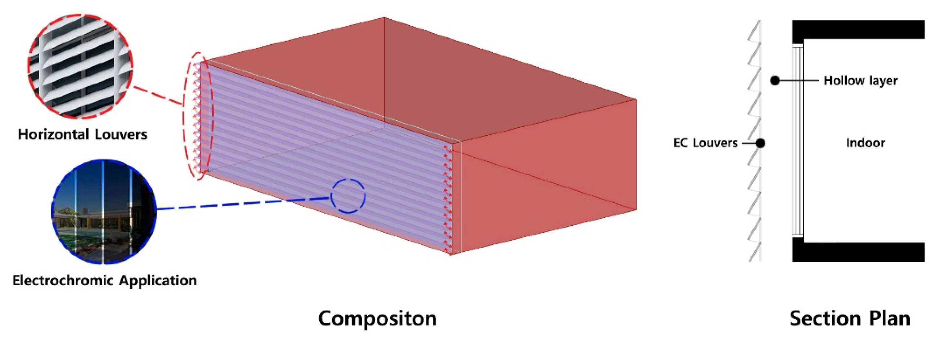
With this background, the objective of this study was to propose a louver with smart glass, and to analyze the range of indoor daylight illuminance that the louver can control. As the analysis method, Rhino 6’s Grasshopper Ladybug tool based on the Radiance 5 engine that can process a large amount of data according to variable control was used. In the case of a louver, since it is exposed to the outside, it was premised on the application of electrochromic, which has excellent safety and durability. Since the horizontal louver can adjust the angle of incident light, it could be used as an auxiliary device for uniform light distribution in the room. In addition, if the kinetic method with EC is adopted, an appropriate amount of light entering the room could be selected.
Therefore, we propose a horizontal louver made of electrochromic material that allows free VLT transition. The proposed EC louver can adjust the angle of the horizontal louver from 0° to 90° according to the situation. When the EC louver is opened and the VLT is set low, it will be able perform a role similar to that of a horizontal louver. In addition, when the EC louver is closed, it will be able to perform a role similar to that of double-glazed windows or Venetian blinds installed outside. The EC louver with this configuration can solve an uneven indoor light distribution pointed out by Kim [11] as a limitation.
Since the proposed envelope is composed of electrochromic, free VLT adjustment is possible. In addition, the angle of the light entering the room can be adjusted by applying a kinetic element. That is, through the angle of the louver and the VLT, the daylight can be adjusted twice. It is possible to adjust the extent to which light can be incident on the building floor as needed. Therefore, it is necessary to consider the change of indoor daylight illuminance for the change of VLT and angle of EC louver. In this study, a simulation method was used to analyze the indoor daylight illuminance according to the conditions of the EC louver.
The purpose of this study is to analyze the range of indoor daylight illuminance change by evenly distributing the indoor light of the proposed EC louver. An analysis was conducted to determine whether an appropriate indoor daylight environment can be created by changing the configuration, VLT, and angle of the EC louver. Ray-tracing simulations were performed on 660 cases according to each variable combination, and the most useful configuration was proposed. The Rhino 6′s Grasshopper program based on the Radiance 5 engine was used to perform the ray-tracing simulation. Daylight illuminance data for 660 cases can be used as a guide for the efficient operation of the EC louver.

1.2. Previous Research Analysis

Previous research can be divided into two areas: energy load reduction of buildings and improvement of indoor environment. Aforementioned studies [7,8,9,10] are in the field of energy load reduction of buildings. Oh et al. [12] have performed monthly energy load comparisons for EC, plain glass, blind, and roll shade models. Ko and colleagues [13] have attempted to analyze the energy performance of the g-value change and window wall ratio (WWR) change of SPD using TRNSYS18 software. They also attempted a study comparing simulation results with mock-up tests [14]. Many studies are trying to analyze thermal properties of smart glass.
Although it is not a field that is being mainly studied, indoor environmental characteristics of smart glass are also being conducted in some studies. Kim [11] has conducted a study on the derivation of the minimum VLT that EC must maintain through LEED v2. Oh et al. [15] have analyzed the energy performance of smart glass. They tried to derive natural light performance of EC using energy and daylight performance index (EDPI). Nundy and colleagues [16] have evaluated the indoor illuminance range and daylight glare index (DGI) when SPD is used for windows. Kim [17] has tried to analyze the color gamut, a concept used in displays for color analysis according to the change in VLT of EC. Although the number of studies in the field of indoor environment is small, some studies are steadily progressing. A study linking the indoor environment with the lighting load has also been conducted. In Cannavale’s study [18], EnergyPlus simulation with useful daylight illuminance (UDI) and DGI was performed for the illuminance (200 W/m2, 250 W/m2, 300 W/m2, respectively) measured from the exterior façade of the building to which EC was applied. The evaluation of the EC façade carried out in terms of UDI and DGI shows that an annual energy saving of 14% is possible.
In order to analyze the effects of louvers on an indoor environment, LEED daylight evaluation and prior research were investigated. LEED certification is the most commonly used eco-friendly building certification system in the world, which has been continuously developed from LEED v1 to LEED v4.1. Previous LEED v2 [19] certifications only required an indoor daylight intensity of 25 fc, which must be secured at a minimum. However, too strong a daylight can have negative effects, so the concept of uniformity had evolved into a concept. In LEED v3 [20], the standard had been changed from 10 fc to 500 fc. The most recent LEED v4.1 provides three evaluation methods [21]. For option 1, it is assessed through spatial daylight autonomy (sDA) and annual sunlight exposure (ASE). sDA is an assessment of whether a space receives at least 300 lx of sunlight during standard operating hours of one year. ASE is a measure of the proportion of floors that receive more than 250 h of direct sunlight exceeding 1000 lx. For option 2 and option 3, it is evaluated how much the illuminance of the indoor floor area achieved 300 lx to 3000 lx at a 9 a.m. and 3 p.m. in the equinox. The range of 300–3000 lx is derived from a useful daylight illuminance (UDI). Option 2 is evaluation by simulation and option 3 is evaluation by actual measurement. The use of LEED’s evaluation index is valid because louvers are devices that can assist daylights installed to control high solar heat and light. In addition, studies have been conducted on several indicators to evaluate indoor lighting performance when using louvers. In the study of Lee et al. [22], daylight autonomy (DA) and UDI were analyzed for four types of louvers (horizontal, vertical, eggcrate and overhang). In the study of Bouberkri and Lee [23], daylight factor (DF), mean hourly illuminance (MHI), DA, and UDI were compared among horizontal, vertical, and overhang types of louvers.
In the study of Uribe et al. [24], sDA and ASE analyses according to the size of the space between louvers of an office building were performed for six climatic zones. In the study of Yasha and colleagues [25], analysis of three louvers horizontally, vertically, and diagonally for eight orientations was performed. In addition, sDA and UDI according to the adjustment angle of each louver were compared.
Elbatran and Ismaeel [26] has been derived sDA and ASE derivation for 36 cases by controlling the variables of screen depth, perforation percentage, and gap width of a building to which Double Skin Facade was applied. Furthermore, the relationship between sDA and ASE was analyzed through correlation analysis. In addition, Elakkad and Ismaeel [27] has been analyzed design guidelines and LEED evaluation systems for office buildings in Egypt through case studies and suggested integrated design guidelines.
Previous studies have used indicators such as sDA, ASE, and UDI to measure the daylight performance of louvers, and these indicators are proving that they are suitable tools for analysis. Furthermore, since the LEED evaluation is based on these indicators, it can be established as an appropriate tool for measuring indoor daylight environments. This study was performed based on the LEED assessment as it aimed to review whether EC louver could elicit an appropriate daylight environment. Additionally, a horizontal type of EC louver that can effectively create an indoor light environment for a deep area has been constructed through previous research.

1.3. Research Methodology

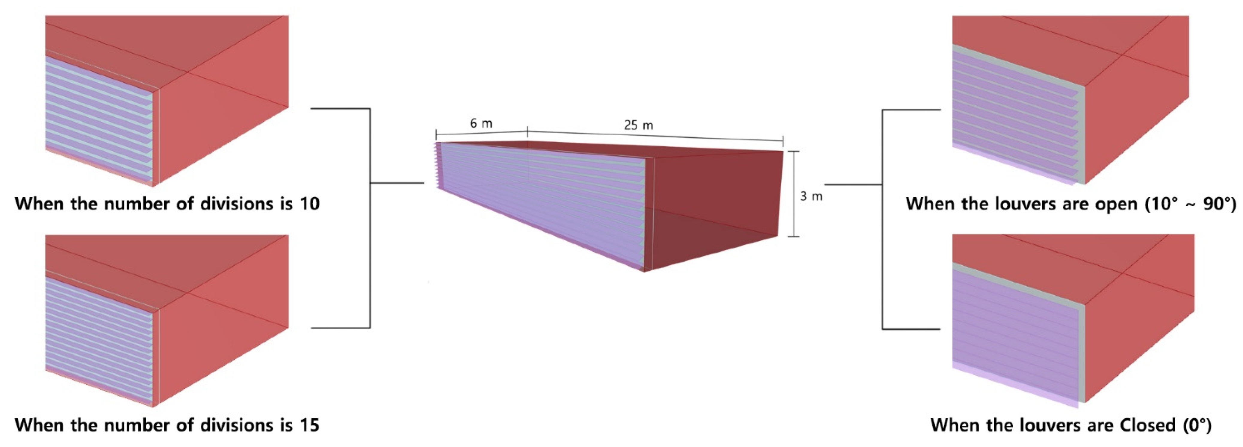
This study is part of a theoretical review to develop an EC louver. Therefore, the indoor daylight uniformity of the EC louver was analyzed. Ray-tracing simulation was performed based on the Radiance engine used in LEED certification [
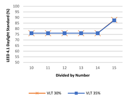
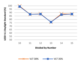
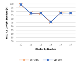
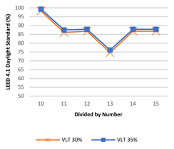
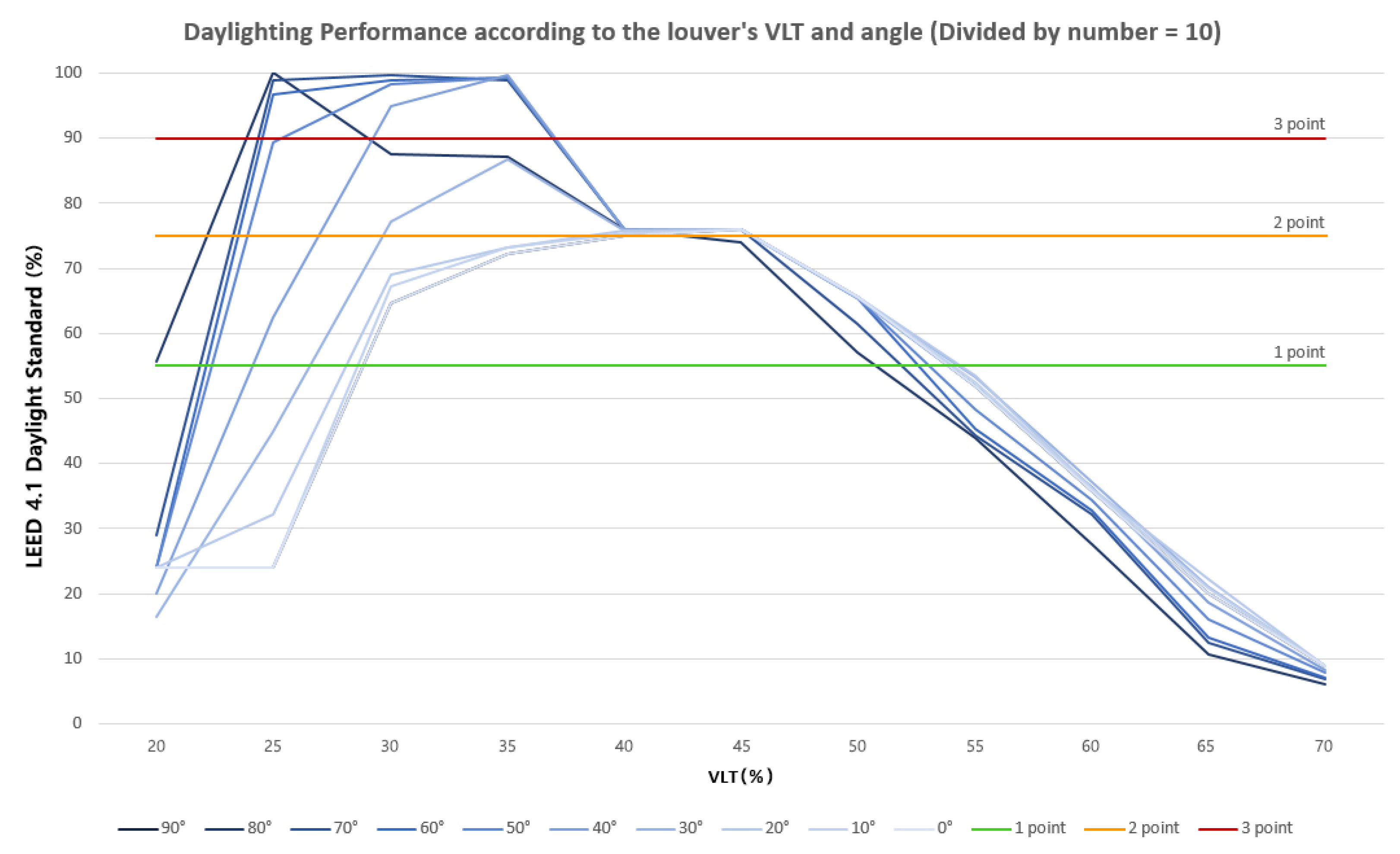
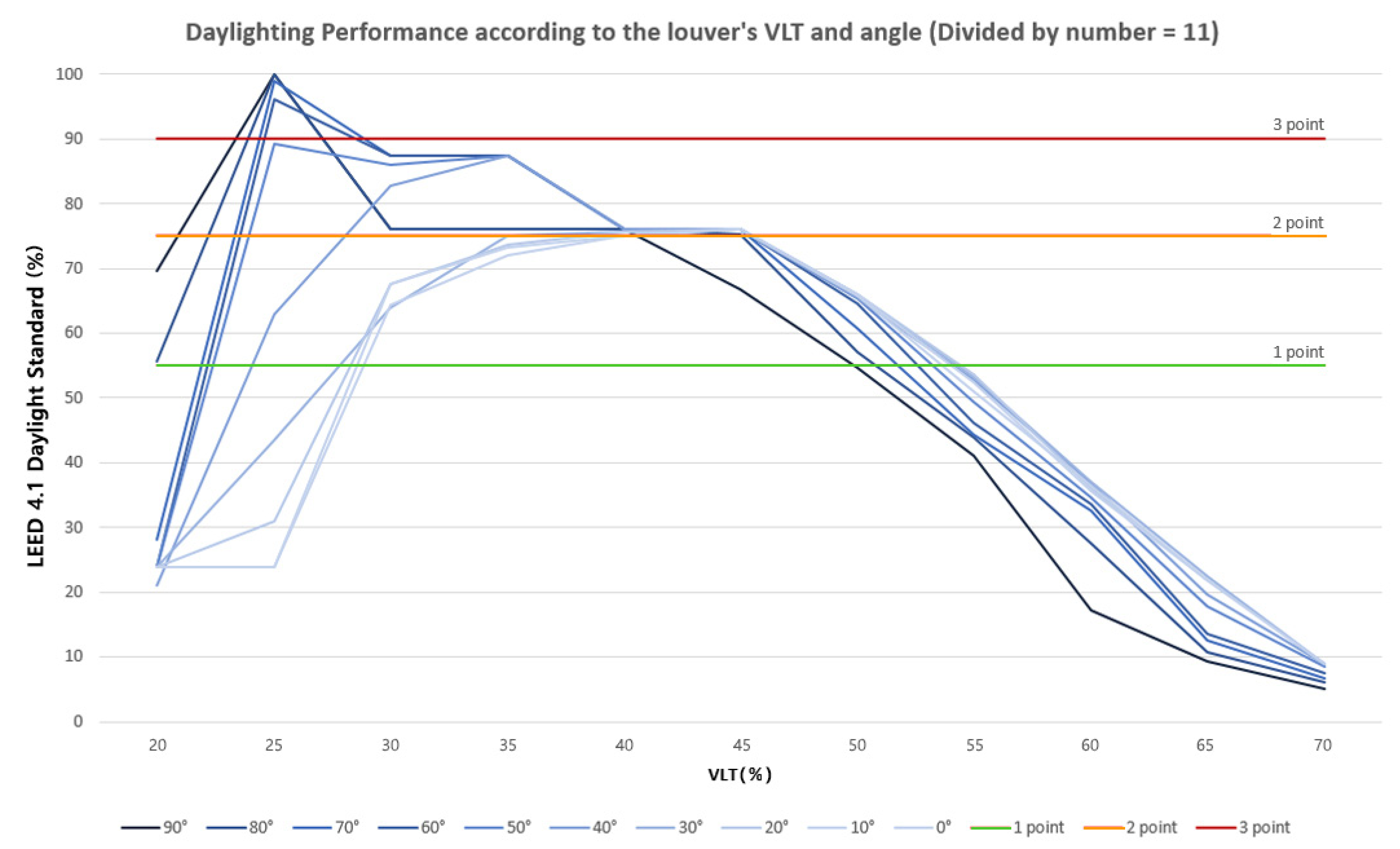
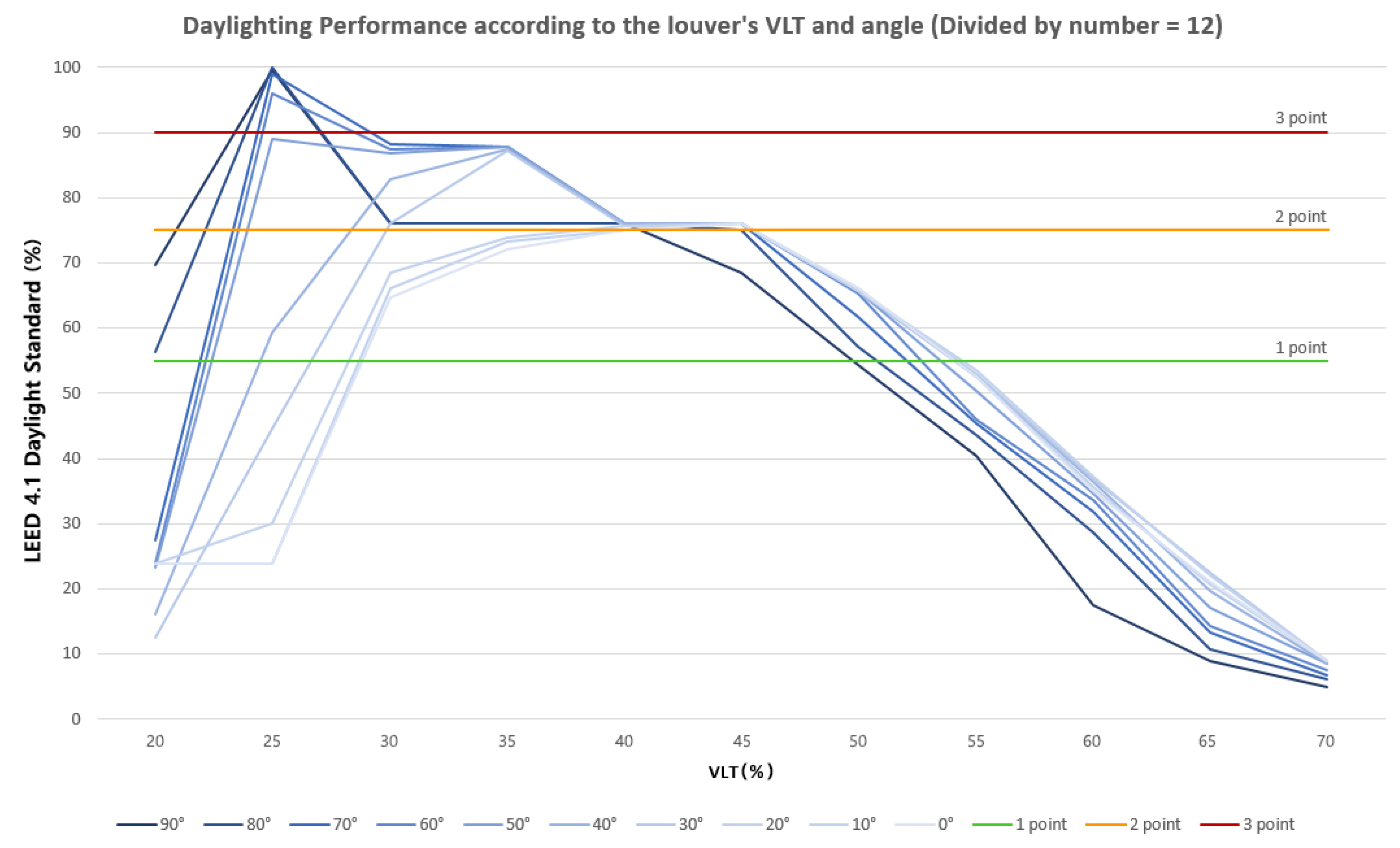
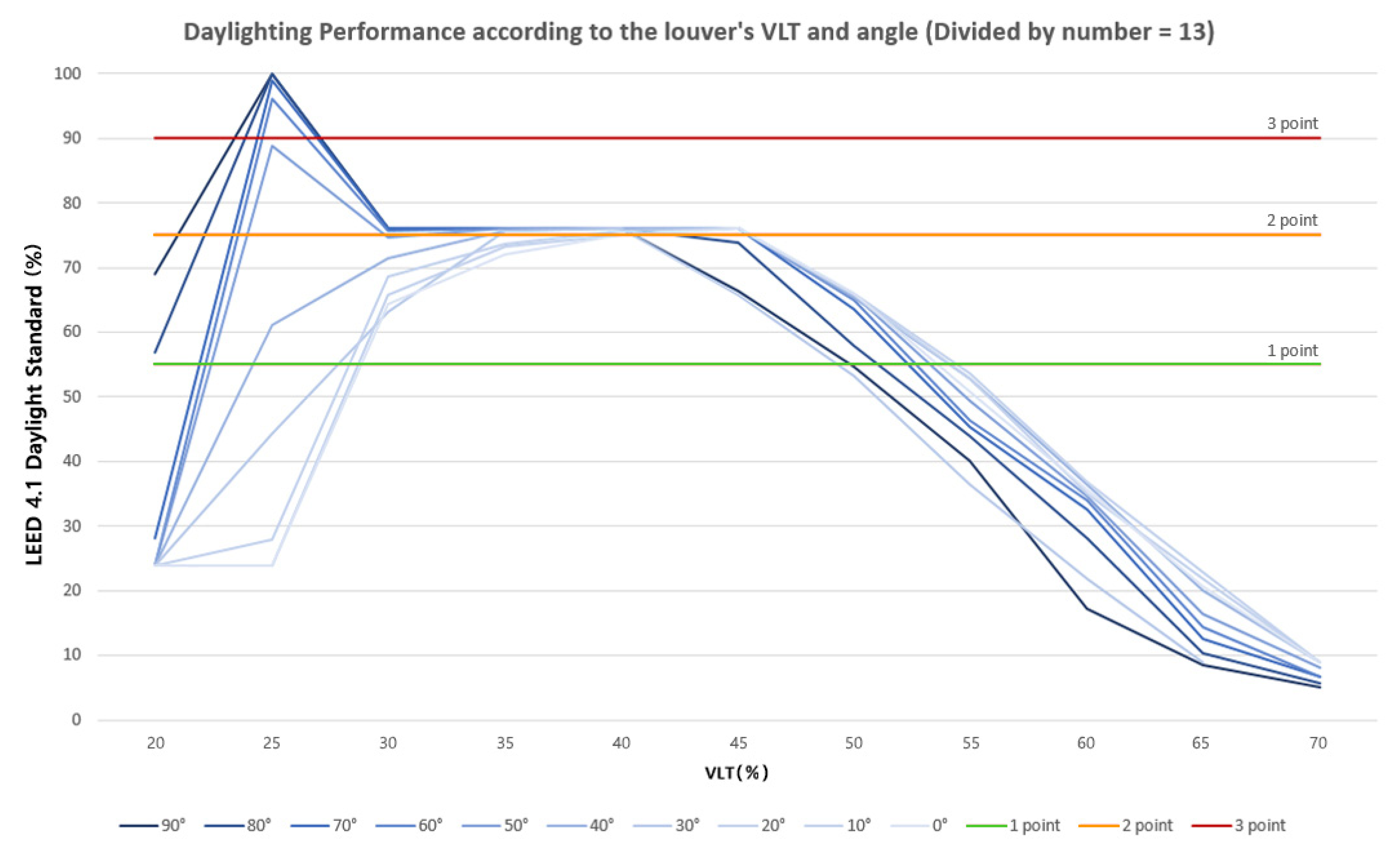
21]. EC louver can adjust the VLT and angle of the shading parts. So, two variables were set, VLT and angle. In addition, a variable for the number of installed louvers was added to examine the impact of constructive aspects. Through this process, 11 VLT variables, 10 angle variables, and six variables for the number of louver installations were set, making a total of 660 case settings.
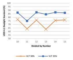
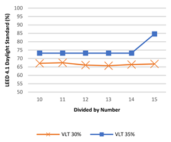
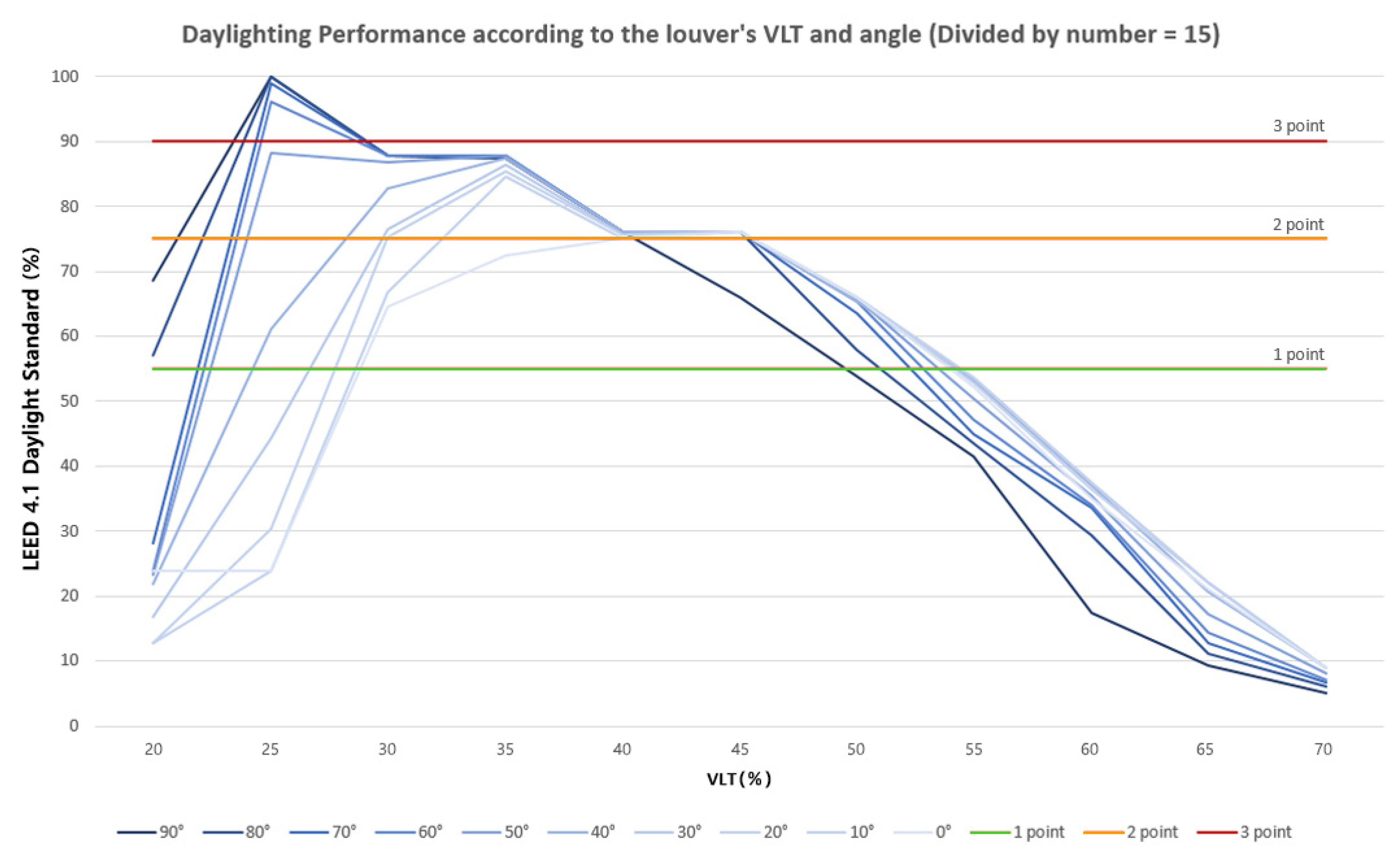
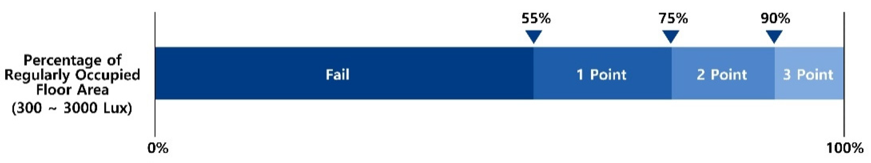
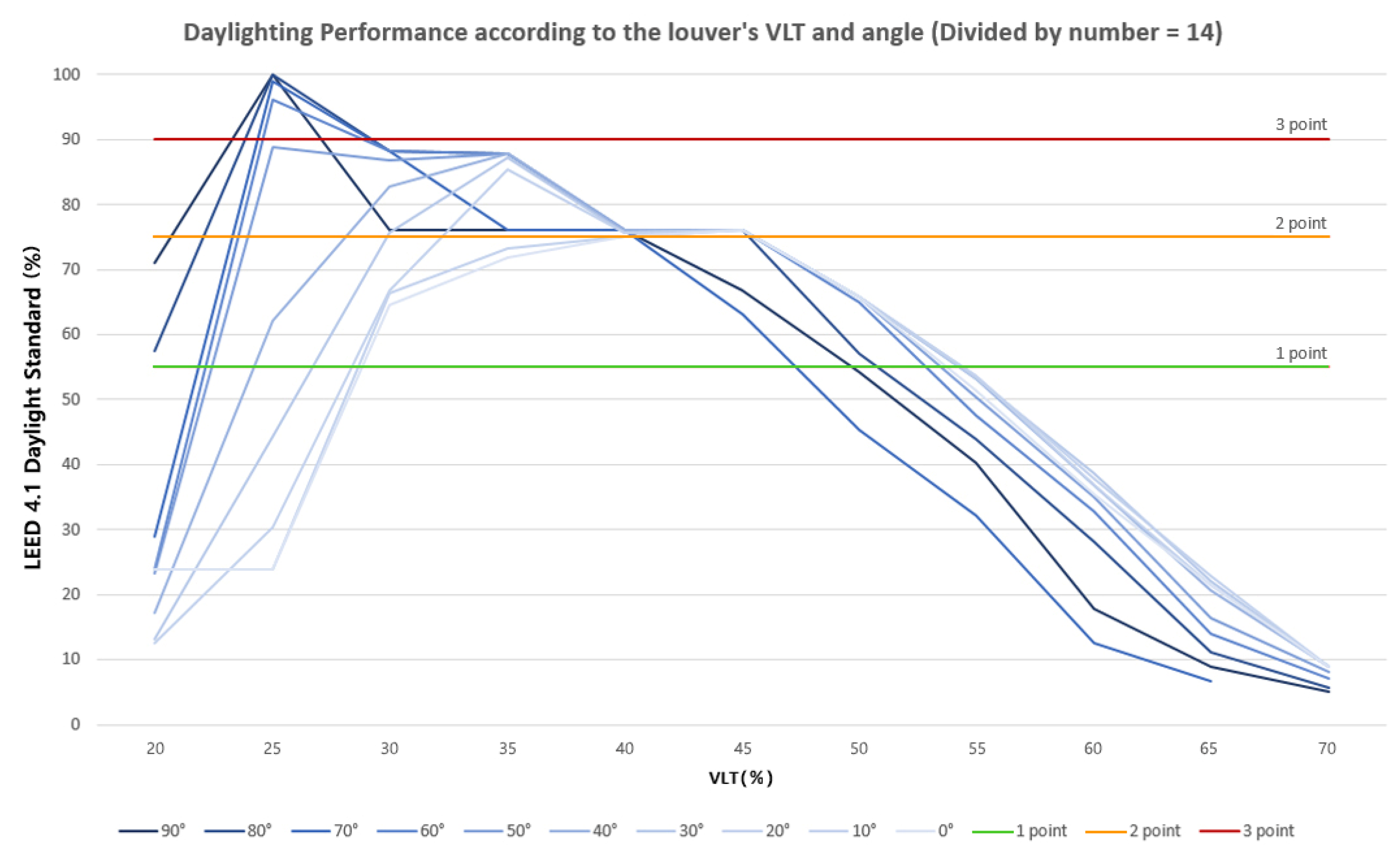
LEED v4.1 daylight standard was used as the evaluation tool [21]. LEED v4.1 daylight evaluation through simulation can select option 1 and option 2. Option 1 provides 1 to 3 points through the calculation of spatial daylight autonomy (sDA) and annual sunlight exposure (ASE). Option 2 evaluates the indoor illuminance. Option 2 provides 1 to 3 points the same as option 1. This study aimed to analyze the light control performance of EC louver through the current standard with enhanced uniformity from the past standard, and therefore was performed through the LEED v4.1 daylight option 2 method. The LEED v4.1 daylight [21] option 2 was evaluated through computer simulations of indoor illuminance at 9 a.m. and 3 p.m. on equinox sunny days for each regularly used space. The illuminance of the indoor floor should be in the range of 300 lx to 3000 lx. When the achievement range is 55%, 1 point is earned. When it is 75%, 2 points are earned. When it is 90%, 3 points are earned.
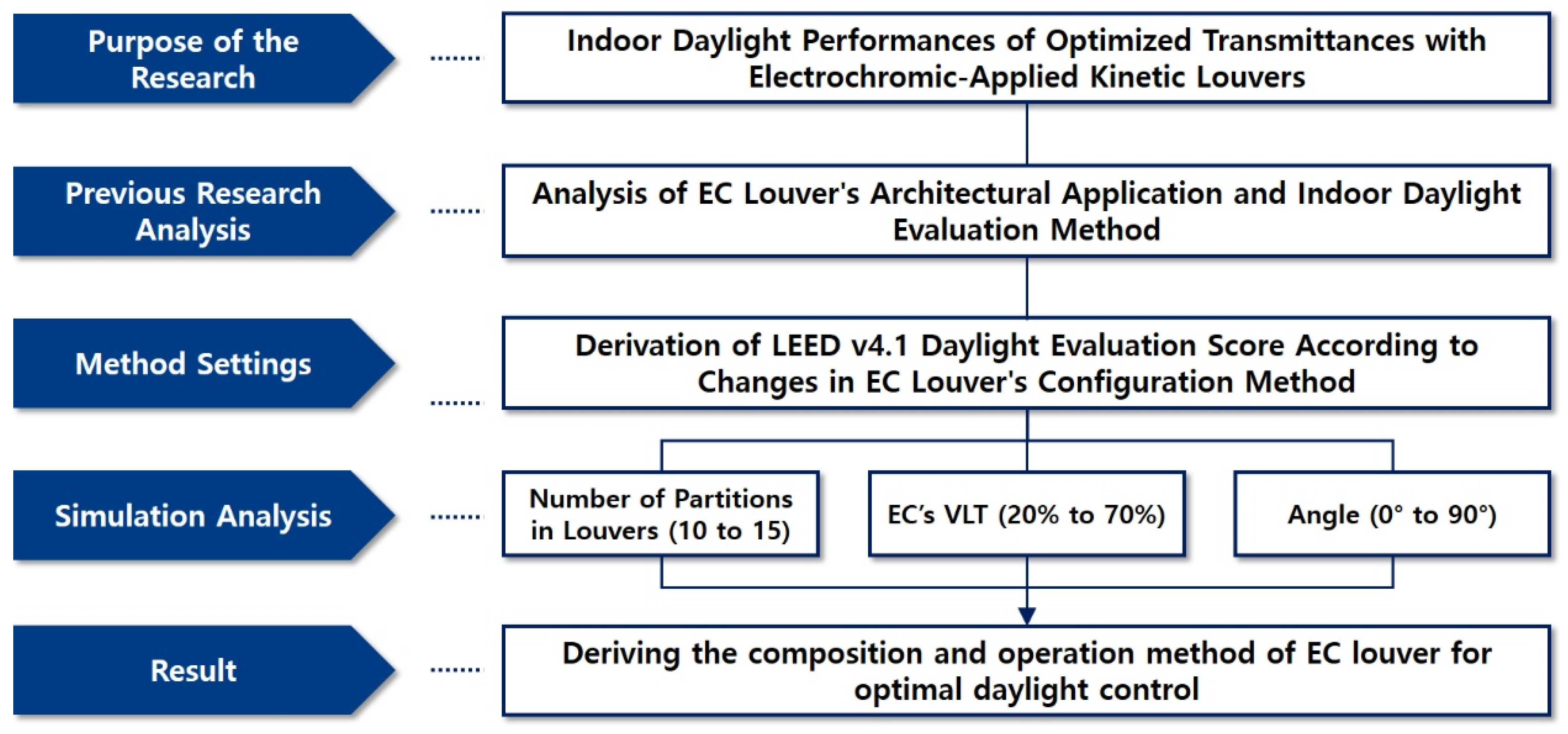
Analysis can be used to derive physical EC louver’s width for optimal daylight control. In addition, data of the indoor daylight environment for each of the louver’s VLT and angle were derived. In conclusion, it is possible to establish the basis for the operation method of the shell to reduce the indoor light environment of the EC louver, which is the purpose of this study. The flow of the study is shown in Figure 1.
The proposed EC louver is expected to have three benefits in the Mixed-Humid zone. First, we can expect an indoor daylight uniformity through the louvers’ VLT and angle adjustment. Second, since an EC louver is used as an external shading device, it can be expected to reduce the indoor cooling load by blocking solar energy. It is also possible to construct a Double Skin Facade with open louvers at the top and bottom and closed louvers at the middle. As a result, we can expect to reduce the cooling and heating load. For each of these three effects, different analysis method settings are required. The indoor daylight uniformity of the EC louver can be performed through ray-tracing simulation analysis. It is possible to predict daylight for the louver’s VLT and angle adjustment. It is also possible to derive the appropriate condition through standards of eco-friendly building certification systems such as LEED. Cooling load analysis of EC louver used as external shading is possible through simulation based on EnergyPlus engine. The solar energy blocking effect changes depending on the g-value and angle of the EC louver, and the cooling load reduction rate of the building can be analyzed. EC louver used as double skin facades should be analyzed through computational fluid dynamics (CFD analysis). It is possible to predict the reduction of the cooling load of the building according to the movement of airflow due to the stack effect in summer. Furthermore, the reduction of the heating load using the hollow layer in winter can be predicted. Based on the three results, it is possible to derive a schedule for EC louver to operate optimally for each season.

2. Analysis Model and Variable Setting

2.1. Analysis Model Setting

The EC louver can operate in a total of three states: (1) when louvers are open horizontally; (2) when all louvers are closed; and (3) when only the uppermost louver and the lowest louver are open to create a stack effect. In this study, the indoor daylight performance was analyzed for both horizontally open louvers and closed louvers. The evaluation criterion was set to LEED v4.1 daylight option 2 mentioned in research methodology. Score is given as shown in Figure 2 according to the ratio of the indoor floor area achieving 300 lx to 3000 lx for the equinox at 9:00 a.m. and 3:00 p.m. [21].
The analysis space was the central core office space proposed in previous studies. It was set to be 25 m × 6 m × 3 m [9]. The proposed EC louver should have a structure that can be completely closed to be used as a Double Skin Facade. For this reason, the width of the louver should be such that the height of the unit is divisible by number. Therefore, the length of separate louver’s width was not calculated and the number divided by the unit height by a variable was used. The gap between windows and louvers, which could be used as a hollow layer, was set to be 300 mm. The material of the louver was EC, and the single glass window of the inner skin was VLT 80%. The composition of the interior walls finish was set with white paint, which is an office wall mainly used in South Korea. The louvers and window were oriented to the south, where they can best receive light. Table 1 and Table 2 are information on the physical properties used in the simulation, and Figure 3 shows the configuration of the proposed EC louver.
The simulation location was in Gwangju (latitude N 36.35° and longitude E 127.39°), South Korea. Gwangju falls under the Mixed-Humid zone. The day of the vernal equinox was set as suggested in LEED Daylight option 2. The Gwangju EnergyPlus weather file (EPW) of ASHRAE international weather for energy calculations (IWEC) was used, and the date was set to March 20 (equinox). At this time, the total amount of cloud cover was 0 and the clear sky was maintained, which satisfies the LEED Daylight evaluation condition. In addition, 9:00 a.m. and 3:00 p.m. on the equinox were set.

2.2. Variable Setting

The EC louver’s variables used in the analysis were set to be three, as shown in Table 3. The first was the number of partitioned louvers. EC louver was designed to form a hollow layer when the louvers are closed. Because of this, the width of the louvers was accounted for as the number divided by the height. The maximum width of each louver was set to be 300 mm. Accordingly, the number of divisions was considered to be at least 10. The range of the number of divisions was set to be 10 to 15 and the width of the louvers was determined to be 200 mm to 300 mm. The second variable was EC’s VLT. According to company O’s product information, EC can theoretically control VLT between 15% and 70% [28]. However, it was recommended to maintain a VLT of 20% or more because EC with VLT adjusted to extreme conditions can cause problems in durability. As a result of measuring the VLT of EC (size of 332 mm × 488 mm) through the WP-4500 window energy profiler, it was confirmed that VLT conversion for more than 20% takes less than 5 min. On the other hand, a VLT conversion of less than 20% was found to exceed 5 min, or VLT could not be maintained. Accordingly, the VLT control variable of EC was set to be 20~70%. A total of 11 were divided in 5% increments. The third variable was the angle of the louver. When louvers are fully closed, 0° was set. When louvers are fully open, 90° was set as shown on Figure 4. Ten variables were set by dividing by 10° increments. A total of 660 case studies were conducted by combining six variables for dividing louvers, 11 VLTs for EC, and 10 variables for angles of louvers. An analysis model was carried out through a parametric modelling method for processing large amounts of information. Rhino 6’s Grasshopper software was used. Grasshopper’s Ladybug tool uses the Radiance 5 engine to enable daylight environment analysis for models created in Rhino 6. The Ladybug tool was used because the LEED daylight evaluation is performed based on Radiance engine simulation.

3. Simulation Results and Analysis

3.1. Simulation Results

LEED v4.1 daylight option 2 simulation was performed on the set model and method, and the following results were obtained. When the number of louvers is 10, there are a total of 11 cases in which three points (over 90% of the floor area that achieved the corresponding illumination) can be obtained for LEED v4.1 daylight option 2. When the VLT is 25%, three points can be obtained for rotation angles of 90°, 80°, 70°, and 60°. With a VLT of 30%, it was possible to achieve three points at 70°, 60°, 50°, and 40°. When VLT was 35%, it was possible to obtain three points for rotation angles of 60°, 50° and 40°. There were a total of 25 cases in which two points (75% or more of the floor area that achieved the illuminance) could be obtained. In LEED v4.1 daylight option 2, there were 36 cases in which a score of 2 or more could be obtained. Results are shown in Table 4 and Figure 5.
Table 5 and Figure 6 show target illuminance achievement rates when the number of louvers is 11. When the VLT was 25%, there were only four cases in which three points could be obtained: 90°, 80°, 70°, and 60°. There were a total of 33 cases where two points could be obtained. There were 37 cases in which two or more points could be obtained.
Table 6 and Figure 7 show target illuminance achievement rates when the number of louvers is 12. It was found that three points could be obtained (90°, 80°, 70°, 60°) when VLT was 25%, the same as when the number was 11. There were a total of 34 cases where two points could be obtained. There were 38 cases in which two or more points could be obtained.
Table 7 and Figure 8 show target illuminance achievement rates when the number of louvers is 13. At VLT of 25%, 3 points could be obtained at 90°, 80°, 70°, and 60°, the same as when 11 or 12 louvers were available. There were 30 cases in which two points could be obtained. Therefore, the number of cases in which more than two points could be obtained was found to be 34.
When the number of louvers is 14, target illuminance achievement rate results are shown in Table 8 and Figure 9. There are four cases where three points could be obtained, just like when the number of louvers was 11, 12, or 13. There were 35 cases in which two points could be obtained. A total of 39 cases in which two or more points could be obtained.
Table 9 and Figure 10 show target illuminance achievement rates when the number of divisions of louvers is 15. As with the previous results, there were a total of four cases where three points could be obtained. There were 37 cases in which two points could be obtained. The total number of cases in which two or more points could be obtained was 41.

3.2. Results Analysis

In previous studies, the optimal louver conditions were considered through analysis of indoor daylight illuminance according to the type of louver, installation location, direction, and perforation rate [22,23,24,25]. In addition, Elakkad and Ismaeel [27] conducted a case study on daylight illuminance and proposed integrated design guidelines for office buildings in Egypt. This paper is different from previous studies because EC louver is newly proposed and analyzed. EC is a smart glass, and VLT can be freely adjusted. Therefore it can create a better indoor daylight environment. In addition, an indoor daylight illuminance environment table according to the VLT, number, and angle of the louver was provided, and the characteristics of the EC louver were analyzed. The characteristics of the found EC louver are as follows.
The number of EC louver divisions that could achieve the most three points of LEED v4.1 daylight option 2 was 10. In other words, the number of EC louver that could create the most optimal indoor daylight environment was 10. However, the number of EC louver that could generally create a good indoor lighting environment by obtaining two points or more was found to be 15. At this time, the number of cases where two or more could be obtained was 41, which was four more than when there were 10.
These results were indicated by several characteristics of the proposed EC louver. When VLT was 40% to 45%, it showed a constant achievement rate of about 75% regardless of the number of louvers or rotation angle. The section with the largest change in achievement rate according to the number of louvers was found to be the VLT 30% to 35% section. Table 10 shows the change in the achievement rate according to the number of divisions of louvers for VLT 30% to 35%.
EC louver of VLT 30% to 45% for 90°, 20° and 10° maintained a constant LEED v4.1 option 2 achievement rate regardless of the number of splits. On the other hand, 80°, 70°, 60°, 50°, 40°, and 30° were confirmed to have a constant change pattern with respect to remaining angles. When the number of divisions increased until 13, the achievement rate of LEED daylight option 2 decreased. When divided into 14 or more, the achievement rate increased. Therefore, when composing the EC louver, the form divided into 13 should be avoided.
Based on this, the following suggestions are made. The number of divisions of EC louver should be 10 to obtain the best indoor illumination effect. The number of divisions of EC louver should be 15 to obtain adequate illumination effects in a large area. Results of this study could provide clues to the construction of EC louver for energy analysis. If a wide VLT control range is required for optimum energy efficiency, the number of divisions of EC louver can be set to be 15. On the other hand, if a wide VLT control range is not required, the number of splits in the EC louver can be configured to be 10. Cross-over studies through follow-up studies are required.

4. Conclusions

4.1. Conclusion of the Research

Recently, smart glass has been developed and commercialized. In architecture, smart glass is applied to windows. However, previous studies have pointed out that smart glass used for windows has limitations because it does not provide an option for an even distribution of daylight indoors. In this study, EC louver was proposed as an alternative to overcome limitations of existing studies. In addition, when using EC louver, the indoor daylight environment was analyzed. Through this study, a range of indoor daylight conditions that can be changed according to variable manipulation of EC Louver have been derived. Results of this study provided us the basis for the composition of EC louver to derive the optimal indoor daylight environment. In addition, programming basic data for operating EC louver were obtained.
LEED v4.1 daylight option 2 was used as the analysis criterion. LEED v4.1 daylight option 2 could be performed through simulation. The target was set as a 25 m × 6 m × 3 m office unit facing south, and the location was set in Gwangju, South Korea. The number of louvers, VLT, and rotation angle were set as manipulation variables. Simulations were performed on a total of 660 cases.
As a result of the simulation, characteristics of EC louver were derived as follows. It was confirmed that when the VLT was 40~45%, the constant LEED v4.1 daylight option 2 evaluation criteria could be achieved regardless of the number of divisions or the angle of adjustment of louvers. When the VLT was 30 to 35%, the score achievement rate was large depending on the number of splits. In particular, when the adjustment angle was 80°, 70°, 60°, 50°, 40°, 30°, the range of change was large. It was confirmed that target illuminance achievement change had a pattern. Taken together, when the number of divisions was 10, the number of cases that could receive three points in the evaluation criteria of LEED v4.1 daylight option 2 was the largest. Furthermore, when the number of divisions was 15, the number of cases where two or more points could be obtained was found to be the highest.
The proposed EC louver have three expected benefits. The first benefit was the daylight effect which was analyzed throughout this study. The second and third benefits were energy saving effects when used as awnings and Double Skins façade. These effects are being studied. Based on results of these two expected benefits of EC louver that have not yet been analyzed, it is judged that final EC louver’s compositions can be selected.

4.2. Research Limitations and Discussion

Because this study was analyzed through simulation, different results might be obtained when applied to real buildings. In order to overcome this limitation, it is necessary to cross-validate with actual buildings. The effectiveness of EC louver can be verified if theory and practice show similar results through mock-up tests using real objects.
In addition, this study only considered the equinoxes 9:00 a.m. and 3:00 p.m. following the method of LEED v4.1 daylight option 2. Analysis of the entire daily routine has limitations as it does not proceed. Therefore, a study to derive the illuminance by time zone for representative seasons, and to compare and analyze it through UDI should be conducted as a follow-up study.
In the case of buildings, since they are not standardized with various shapes, they also have limitations in not having the same results. Therefore, the collection of information should proceed assuming EC louver in various types of buildings. The pattern of results should be analyzed. Alternatively, a fast-developing deep learning technology may be considered. If the building can control the light based on the patterned data, it is judged that it will be possible to provide a comfortable environment for the occupants for a long time. If limitations are overcome through follow-up research, EC louver will be expected to contribute to sustainable architecture by achieving indoor daylight environmental control.

Author Contributions

J.-H.K. and S.-H.H. designed the research settings; J.-H.K. performed the evaluations; J.-H.K. and S.-H.H. analyzed the data; S.-H.H. verified the analysis results; J.-H.K. and S.-H.H. wrote the paper. All authors have read and agreed to the published version of the manuscript.

Funding

This research was funded by the Ministry of Science and ICT of the Korean Government (Project No.: NRF-2021R1A2C2011893).

Institutional Review Board Statement

Not applicable.

Informed Consent Statement

Not applicable.

Data Availability Statement

Not applicable.

Acknowledgments

This research was supported by a grant from the Basic Science Research Program through the National Research Foundation of Korea (Development of Smart Building Envelopes towards Implementation of Vernacular Energyscape).

Conflicts of Interest

The authors have no conflicts of interest to disclose.

References

  1. Gran View Research. Smart Glass Market Size, Share & Trends Analysis Report by Technology (SPD, PDLC, Liquid Crystal, Electrochromic), by Application (Consumer Electronics, Architectural, Transportation), and Gegment Forecasts. Available online: https://www.grandviewresearch.com/industry-analysis/smart-glass-market (accessed on 20 December 2021).
  2. Markets and Markets. Smart Glass Market with COVID-19 Impact by Technology (Suspended Particle Display, Electrochromic, Liquid Crystal), Application (Architecture, Transportation, Consumer Electronics), and Geography—Global Forecast to 2025. Available online: https://www.marketsandmarkets.com/Market-Reports/smart-glass-market-907.html (accessed on 20 December 2021).
  3. Global Information, Inc. Smart Glass Market Size by Technology (Active, Passive), by Application, Industry Analysis Report, Regional Outlook, Growth Potential, Price Trends, Competitive Market Share & Forecast, 2021–2027. Available online: https://www.giiresearch.com/report/gmi1008679-smart-glass-market-size-by-technology-active.html (accessed on 20 December 2021).
  4. Svensson, J.; Granqvist, C.G. Electrochromic coatings for smart windows: Crystalline and amorphous WO3 films. Thin Solid Films 1985, 126, 31–36. [Google Scholar] [CrossRef]
  5. Barrios, D.; Vergaz, R.; Sanchez-Pena, J.M.; Granqvist, C.G.; Niklasson, G.A. Toward a quantitative model for suspended particle devices: Optical scattering and absorption coefficients. Sol. Energy Mater. Sol. Cells 2013, 111, 115–122. [Google Scholar] [CrossRef] [Green Version]
  6. Yoo, S. Latest Research Trends in the Field of Electrochromic Electrode Catalysts. CHERIC. 2011. Available online: https://www.cheric.org/research/ip/ipview.php?code=p201302 (accessed on 20 December 2021).
  7. Abdelsalam, A. Conventional Fixed Shading Devices in Comparison to an Electrochromic Glazing System in Hot, Dry Climate. Energy Build. 2013, 59, 104–110. [Google Scholar]
  8. Nicholas, D.; Arman, S.; Stephen, S.; Delia, J. A Comparative Energy Analysis of Three Electrochromic Glazing Technologies in Residential Building. Appl. Energy 2017, 192, 95–109. [Google Scholar]
  9. Kim, J.; Hong, J.; Han, S. Optimized Physical Properties of Electrochromic Smart Windows to Reduce Cooling and Heating Loads of Office Buildings. Sustainability 2021, 13, 1815. [Google Scholar] [CrossRef]
  10. Min, J.; Hong, H. A Study on the Energy Performance Evaluation of a Smart Skin for Reducing Cooling Load of Building Envelope in Office Building. Korean J. Air-Cond. Refrig. Eng. 2018, 30, 546–557. [Google Scholar]
  11. Kim, J. A Study on the Applicability of Electrochromic Facade to Improve Energy Performance in Office Space. Master’s Thesis, Chonnam National University, Gwangju, Korea, 2021. [Google Scholar]
  12. Oh, M.; Tae, S.; Hwang, S. Analysis of Heating and Cooling Loads of Electrochromic Glazing in High-Rise Residential Buildings in South Korea. Sustainability 2018, 10, 1121. [Google Scholar] [CrossRef] [Green Version]
  13. Ko, Y.; Hong, H.; Min, J. Energy Performance Evaluation of Responsive Smart Windows Applying SPD According to Window Area Ratio and SHGC Range. Korean J. Air-Cond. Refrig. Eng. 2020, 32, 441–447. [Google Scholar]
  14. Ko, Y.; Oh, H.; Hong, H.; Min, J. Energy Consumption Verification of SPD Smart Window, Controllable According to Solar Radiation in South Korea. Energies 2020, 13, 5643. [Google Scholar] [CrossRef]
  15. Oh, M.; Jang, M.; Moon, J.; Roh, S. Evaluation of Building Energy and Daylight Performance of Electrochromic Glazing for Optimal Control in Three Different Climate Zones. Sustainability 2019, 11, 287. [Google Scholar] [CrossRef] [Green Version]
  16. Nundy, S.; Ghosh, A. Thermal and Visual Comfort Analysis of Adaptive Vacuum Integrated Switchable Suspended Particle Device Window for Temperate Climate. Renew. Energy 2020, 156, 1361–1372. [Google Scholar] [CrossRef]
  17. Kim, J.; Han, S. A Quantification Procedure for Interior Performance of Architectural Openings Associated with Dye-Sensitized Solar Cells. Sustainability 2019, 11, 6461. [Google Scholar] [CrossRef] [Green Version]
  18. Cannavale, A.; Ayr, U.; Fiorito, F.; Martellotta, F. Innovative Electrochromic Devices: Energy Savings and Visual Comfort Effect. Energy Procedia 2018, 148, 900–907. [Google Scholar] [CrossRef]
  19. Leadership in Energy and Environmental Design. LEED v2.0 for Building Design and Construction. 2021. Available online: https://www.usgbc.org/credits?Version=%22v2.0%22 (accessed on 20 December 2021).
  20. Leadership in Energy and Environmental Design. LEED v3.0 for Building Design and Construction. 2021. Available online: https://www.usgbc.org/credits?Version=%22v2009%22 (accessed on 20 December 2021).
  21. Leadership in Energy and Environmental Design. LEED v4.1 for Building Design and Construction. 2021. Available online: https://build.usgbc.org/bdc41 (accessed on 20 December 2021).
  22. Lee, K.S.; Han, K.J.; Lee, J.W. The Impact of Shading Type and Azimuth Orientation on the Daylighting in a Classroom-Focusing on Effectiveness of Façade Shading, Comparing the Results of DA and UDI. Energies 2017, 10, 635. [Google Scholar] [CrossRef] [Green Version]
  23. Boubekri, M.; Lee, J. A Comparison of Four Daylighting Metrics in Assessing the Daylighting Performance of Three Shading Systems. J. Green Build. 2017, 12, 39–53. [Google Scholar] [CrossRef]
  24. Uribe, D.; Bustamante, W.; Vera, S. Potential of Perforated Exterior Louvers to Improve the Comfort and Energy Performance of an Office Space in Different Climates. Build. Simul. 2018, 11, 695–708. [Google Scholar] [CrossRef]
  25. Yasha, J.; Guy, A.; Yaniv, H.; Isaac, G. Evaluating the Influence of Varied External Shading Elements on Internal Daylight Illuminances. Buildings 2020, 10, 22. [Google Scholar] [CrossRef] [Green Version]
  26. ElBatran, R.M.; Ismaeel, W.S.E. Applying a Parametric Design Approach for Optimizing Daylighting and Visual Comfort in Office Buildings. Ain Shams Eng. J. 2021, 12, 3275–3284. [Google Scholar] [CrossRef]
  27. Elakkad, N.; Ismaeel, W.S.E. Coupling Performance-prescriptive Based Daylighting Principles for Office Buildings: Case study from Egypt. Ain Shams Eng. J. 2021, 12, 3263–3273. [Google Scholar] [CrossRef]
  28. ORION NES. Available online: http://www.orionnes.co.kr/Vmodel (accessed on 24 December 2021).
Figure 1. Research flowchart and research scope.
Buildings 12 00263 g001
Figure 2. LEED v4.1 daylight option 2 criteria (reconstructed the Daylight evaluation of LEED v4.1 Building Design and Construction).
Buildings 12 00263 g002
Figure 3. Proposed EC louver.
Buildings 12 00263 g003
Figure 4. Configuration of analysis model.
Buildings 12 00263 g004
Figure 5. Target illuminance achievement rate graph when the number of divisions of louvers is 10.
Buildings 12 00263 g005
Figure 6. Target illuminance achievement rate graph when the number of divisions of louvers is 11.
Buildings 12 00263 g006
Figure 7. Target illuminance achievement rate graph when the number of divisions of louvers is 12.
Buildings 12 00263 g007
Figure 8. Target illuminance achievement rate graph when the number of divisions of louvers is 13.
Buildings 12 00263 g008
Figure 9. Target illuminance achievement rate graph when the number of divisions of louvers is 14.
Buildings 12 00263 g009
Figure 10. Target illuminance achievement rate graph when the number of divisions of louvers is 15.
Buildings 12 00263 g010
Table 1. Setting the physical properties of the light-transmitting material.
PartsMaterialVisible Light TransmittanceRefractive Index
WindowGlass80%1.52
LouverElectrochromic20–70%1.52
Table 2. Setting the physical properties of interior finishing material.
PartsMaterialRoughnessSpecularity
WallWhite Paint0.0120.05
Ceiling
Floor
Table 3. Manipulative variables.
DivisionNumber of Partitions in LouversEC’s VLTAngle of Louvers
Range10 to 1520% to 70%
(5% unit)
0° to 90°
(in 10° increments)
Table 4. Target illuminance achievement rates when the number of divisions of louvers is 10.
AngleEC Visible Light Transmittance
20%25%30%35%40%45%50%55%60%65%70%
90°71%100%76%76%76%66%54%40%17%6%5%
80°56%100%88%87%76%74%57%44%28%11%6%
70°29%99%100%99%76%76%61%44%32%13%7%
60°24%97%99%99%76%76%65%45%33%13%7%
50°24%89%98%99%76%76%65%48%34%16%8%
40°20%63%95%100%76%76%65%52%36%19%8%
30°16%45%77%87%76%76%65%53%37%21%9%
20°24%32%69%73%76%76%66%54%36%22%9%
10°24%24%67%73%75%76%66%53%36%21%9%
24%24%65%72%75%76%66%52%36%20%9%
Table 5. Target illuminance achievement rates when the number of divisions of louvers is 11.
AngleEC Visible Light Transmittance
20%25%30%35%40%45%50%55%60%65%70%
90°70%100%76%76%76%67%55%41%17%9%5%
80°56%100%76%76%76%75%57%44%28%11%6%
70°28%99%88%88%76%76%61%44%33%13%7%
60°24%96%88%88%76%76%65%46%34%14%8%
50°24%89%86%88%76%76%65%49%35%18%9%
40°21%63%83%88%76%76%65%53%37%20%9%
30°24%44%64%75%76%76%66%53%37%23%9%
20°24%31%68%74%76%76%66%54%36%22%9%
10°24%24%68%73%75%76%66%53%36%22%9%
24%24%64%72%75%76%66%51%36%22%9%
Table 6. Target illuminance achievement rates when the number of divisions of louvers is 12.
AngleEC Visible Light Transmittance
20%25%30%35%40%45%50%55%60%65%70%
90°70%100%76%76%76%69%54%40%18%9%5%
80°56%100%76%76%76%75%57%44%29%11%6%
70°28%99%88%88%76%76%62%45%32%13%7%
60°24%96%88%88%76%76%65%46%34%14%8%
50°23%89%87%88%76%76%66%50%35%17%9%
40°16%59%83%88%76%76%66%53%36%20%9%
30°13%45%76%87%76%76%66%53%37%23%9%
20°24%30%69%74%76%76%66%54%37%22%9%
10°24%24%66%73%75%76%66%53%36%21%9%
24%24%65%72%75%76%66%53%35%21%9%
Table 7. Target illuminance achievement rates when the number of divisions of louvers is 13.
AngleEC Visible Light Transmittance
20%25%30%35%40%45%50%55%60%65%70%
90°69%100%76%76%76%66%55%40%17%9%5%
80°57%100%76%76%76%74%58%44%28%10%6%
70°28%99%76%76%76%76%64%45%33%13%7%
60°24%96%76%76%76%76%65%46%34%14%7%
50°24%89%75%76%76%76%66%49%35%16%8%
40°24%61%71%76%76%76%65%53%36%20%9%
30°24%44%63%84%76%76%66%53%36%22%9%
20°24%28%69%74%76%76%66%54%37%23%9%
10°24%24%66%73%75%76%66%53%35%22%9%
24%24%64%72%75%76%66%51%36%21%9%
Table 8. Target illuminance achievement rates when the number of divisions of louvers is 14.
AngleEC Visible Light Transmittance
20%25%30%35%40%45%50%55%60%65%70%
90°71%100%76%76%76%67%54%40%18%9%5%
80°58%100%88%88%76%76%57%44%28%11%6%
70°29%99%88%87%76%76%63%45%32%13%7%
60°24%96%88%88%76%76%65%48%33%14%7%
50°23%89%87%88%76%76%66%50%35%16%8%
40°17%62%83%88%76%76%66%53%37%21%9%
30°13%44%76%87%76%76%66%53%39%22%9%
20°13%30%67%85%76%76%66%54%38%23%9%
10°24%24%66%73%75%76%66%54%37%21%9%
24%24%65%72%75%76%66%51%35%21%9%
Table 9. Target illuminance achievement rates when the number of divisions of louvers is 15.
AngleEC Visible Light Transmittance
20%25%30%35%40%45%50%55%60%65%70%
90°69%100%88%88%76%66%54%41%18%9%5%
80°57%100%88%88%76%76%58%44%29%11%6%
70°28%99%88%88%76%76%64%45%34%13%7%
60°24%96%88%88%76%76%65%47%34%14%7%
50°23%88%87%88%76%76%66%50%35%17%8%
40°22%61%83%88%76%76%65%53%37%21%9%
30°17%44%76%86%76%76%66%54%38%22%9%
20°13%30%75%85%76%76%66%54%38%22%9%
10°13%24%67%85%75%76%66%53%36%22%9%
24%24%65%73%75%76%66%52%35%21%9%
Table 10. Analysis of target illuminance attainment rate for louvers of VLT 30% to 35%.
Change in Achievement Rate According to LEED v4.1 Daylight Option 2 in the Number of Divisions of Louvers
Buildings 12 00263 i001 Buildings 12 00263 i002 Buildings 12 00263 i003
90°80°70°
Buildings 12 00263 i004 Buildings 12 00263 i005 Buildings 12 00263 i006
60°50°40°
Buildings 12 00263 i007 Buildings 12 00263 i008 Buildings 12 00263 i009
30°20°10°
Publisher’s Note: MDPI stays neutral with regard to jurisdictional claims in published maps and institutional affiliations.

