Abstract
In the last few decades, the application of lightweight cold-formed composite steel–concrete structural systems has constantly been increasing within the field of structural engineering. This can be explained by efficient material usage, particularly noticeable when using cold-formed built-up sections and the innovative types of shear connections. This paper summarises an overview of the development of the cold-formed composite steel–concrete floor systems. Additionally, it provides the background, planned activities, and preliminary results of the current LWT-FLOOR project, which is ongoing at the University of Zagreb, Faculty of Civil Engineering, Croatia. The proposed structural system is formed of built-up cold-formed steel beams and cast-in-place concrete slabs that are interconnected using an innovative type of shear connection. Preliminary analytical and numerical results on the system bending capacity are presented. Obtained results are mutually comparable. The resistance of the fixed beam solution is governed by the resistance of the steel beam, while pinned beam solution is governed by the degree of shear connection without the influence of the increased number of spot welds in the steel beam.
1. Introduction
One of the key strategies to reduce human impact on Earth is to completely rethink our present lifestyle, especially the one led in industrialised countries. One of the critical aspects of this new lifestyle is sustainability, including reducing raw material and energy consumption. This can be achieved through innovations that will maximise the values of the structural components and building materials during their lifecycle. Although a widespread, systematic approach is still lacking, individual scientific projects are well aware of this problem and provide relevant solutions. An excellent example of this is the application of the composite cold-formed steel–concrete solutions that significantly reduce material consumption and contribute to the aforementioned change of the present unsustainable lifestyle.
The known fact is that composite steel–concrete systems are generally one of the most cost-effective structural systems applied in multi-storey buildings. The main reason behind this is that composite steel–concrete solutions integrate structural efficiency and the speed of construction. The structural efficiency results from the effective usage of structural materials, namely steel and concrete, thus omitting their inherent disadvantages. On the other hand, construction speed is enhanced since propping and formwork installation can be significantly reduced or even completely avoided.
However, despite all the advantages and benefits of composite structural systems, so far, they have not had the chance to be applied to any greater extent, i.e., certainly not to the extent that they deserve [1]. According to Ahmed et al. [2], the main forces driving the research within the field of composite steel–concrete structural systems are related to the development of innovative construction methods and new structural products, the best applications of new as well as underdeveloped materials, and considerations of socioeconomic and environmental consequences towards sustainability and resilience. The proposed structural flooring systems analysed in this work that use cold-formed steel (CFS) profiles combined with concrete cover all the aforementioned research aspects.
The purpose of this paper is to provide an overview of the development of the cold-formed composite steel–concrete structural systems. Furthermore, the paper gives insight into the background, planned activities, and preliminary results of the current LWT-FLOOR project, which is ongoing at the University of Zagreb, Faculty of Civil Engineering, Croatia. The proposed structural system is formed of built-up cold-formed steel beams and cast-in-place concrete slabs that are interconnected using an innovative type of shear connection. Preliminary analytical and numerical results on the system bending capacity are presented.
2. Materials and Methods
2.1. Overview of the Cold-Formed Steel Application in Composite Steel–Concrete Structural Systems
Generally, the interaction between steel and concrete has been widely used in structural engineering due to multiple benefits that result from combining desirable mechanical properties of each material. This explains why concrete is reinforced with steel rebars, or composite steel–concrete structural systems are used when higher resistance values or larger spanning capabilities are required. The advantages of structural steel are high tensile strength and ductility, while concrete ones are high stiffness and high compressive strength [3]. Therefore, using composite beams as structural flooring systems has a couple of benefits over the non-composite ones [4]:
- Material savings between 30% and 50% of structural steel can be achieved.
- Increased stiffness can reduce beam height for the same span, which can lead to benefits either as lower storey heights, decrease in cladding costs, more space for mechanical services, and increased usable space for the same building height.
Today, the most common version of composite beam comprises a hot-rolled steel beam and a floor slab, either concrete or composite steel–concrete, that interact through the application of shear connectors. In this form, the floor slab enhances the resistance of the steel beam by increasing its local and global stability. This observation can be further implemented to optimise the structural steel material so that cold-formed steel sections could be utilised instead of hot-rolled sections.
Application of cold-formed profiled steel sheeting has, for some time now, extensively been used in the construction of structural floor systems, i.e., the composite steel–concrete slabs [2]. Similarly, cold-formed steel profiles have also been investigated as soffits within the composite steel–concrete beams and columns [5,6,7]. However, such structural systems have not been applied to a greater extent. Nevertheless, the profiled steel sheeting used in the proposed solutions becomes an integral part of a structural system where it performs many different roles in the construction and the exploitation phases, such as [4]:
- Provides a working platform and protects the workers below;
- Supports the loads during construction and may eliminate the need for propping;
- Acts as permanent formwork for the concrete slab;
- If either mechanical or frictional interlock is being realised, the sheet can be considered to contribute to the required area of the primary tension reinforcement calculated for the slab;
- When through-deck welded stud shear connectors are used, the composite slab may be considered to restrain the steel beams.
The stated facts show enormous potential for further development of composite structural solutions using cold-formed steel elements and innovative shear connections. This potential is the result of the engineering point-of-view and the socioeconomic and environmental point-of-view to develop a sustainable and resilient ecosystem related to the built environment.
An extensive overview of the current development in composite steel–concrete beams and flooring systems can be found in [2]. Cold-formed steel has seen extensive research and application in composite slabs. However, it has not been extensively used in composite beam solutions where the downstand beam is made of cold-formed built-up steel sections and works together with the concrete flange, although such an idea has been around for a couple of decades [8]. Some advantages of composite beams using cold-formed built-up steel sections and concrete slabs are flexibility in architectural and beam cross-section design, the possibility of shallow slab depths, easy adaptation to irregular geometry, enabling reduction of self-weight, etc. However, the behaviour of such structural solutions has not been, up until a recent couple of years, investigated to a greater extent.
Further optimisation of composite systems can also be achieved by reducing self-weight with compact concrete with lightweight aggregates [9]. The authors of the paper [9] conducted a parametric study and summarised the results of the numerical analyses on the composite steel and concrete beams with standard and lightweight concrete slabs. In the cases of reducing composite beam self-weight, systems tend to vibrate more easily under human activities, and vibrational aspects of such systems are very important [10].
Hanaour [8] was among the first to examine the behaviour of composite beams with a cold-formed section using various shear connector types. Tests were conducted on composite beams using a steel cross-section consisting of two cold-formed channel sections. These channel sections were connected back-to-back by self-drilling screws with welded or screwed channel shear connectors over which the concrete slab is cast. Additionally, tests were conducted on composite beam with two cold-formed Z sections connected on the bottom with a plate and on top with a concrete plank generating a box section using 10 mm post-installed bolts as shear connectors. The obtained results show high ductility and capacity of beams when proper design and execution is applied.
Lakkavalli and Liu [11] conducted tests on twelve large-scale composite slab joists consisting of cold-formed steel C-sections and concrete to investigate behaviour and strength and to assess the effectiveness of the shear transfer mechanism. C-sections were partially embedded into the concrete slab for all specimens, so that top flanges were set into the concrete by the distance, which corresponded to half of the slab thickness. In addition to variation of the shear connection type and its spacing, the C-section thickness was also varied within the specimens. Results showed that the shear transfer mechanism using bent-up tabs performed the best when ultimate capacity is compared, followed by drilled holes and self-drilling screws. The results also showed that reduction of shear transfer spacing did not result in capacity increase which may be a consequence of overlapping of stress fields. Finally, the obtained experimental capacities of beam specimens were approximately 19% higher than the theoretically calculated capacities based on push-out test results.
Hsu et al. [12] proposed a new composite beam system consisting of a reinforced concrete slab on a corrugated metal deck, back-to-back cold-formed steel joists, and a continuous cold-formed furring shear connector. A shear connector is screwed to the joist top flange through the metal deck. Conducted tests on composite beams showed that the composite sections could reach ultimate strength without local shear or buckling failure when the proposed furring shear connector is used. In addition, the paper proposed analysis and design methods that can predict load-deflection behaviour and flexural strength of the beams and shear strength of the fasteners.
In [13,14], authors studied the structural behaviour of composite beams that integrate cold-formed steel with Ferro-cement slabs through a bolted-type shear connection. Parametric studies on several wire mesh variations in a Ferro-cement slab, the thickness of the steel section, and bolt diameter were carried out. Results show that failure occurs due to concrete crushing for thicker steel sections, while thinner steel sections fail due to sudden buckling. The shear connectors proved to have adequate strength to provide full shear connection and to transfer longitudinal shear force without failure. An increase of wire mesh layers resulted in greater strength capacity and improved crack formation. Finally, according to the analysis results, the ultimate strength capacity of these composite beams can be calculated by constitutive laws agreed by Eurocode 4.
Khadavi and Tahir [15] conducted research related to the bending resistance of encased composite beams composed of closed steel profiles filled with concrete. These closed profiles consist of two cold-formed C-sections oriented toe to toe and kept in place by a profiled sheeting installed on the beam top to increase stability and bearing performance. Shear connection is obtained using bent reinforcement bars. The proposed solution results show that using closed shapes of steel profiles can improve the bending strength as the confinement contributed by the concrete decreases the local buckling of the steel section. At the same time, the use of reinforcement as shear connectors further increases the bending and shear resistance and additionally stiffens the proposed beam. Similar composite cross-sections were researched by Salih et al. [16]. The results showed that filled beams have a higher bearing capacity than typical slender sections by reaching the yield stress. The proposed methods used in research proved to be applicable for calculating the ultimate limit state of the composite system according to the method from EC4. The continuous shear connection helped to move the neutral axis upward in the composite cross-section, which ensures that the steel top flange does not buckle under compression. Finally, research has shown that a partially encased steel beam increases flexural capacity.
Leal and Batista [17,18] present the investigation on the behaviour of structural composite floor system composed of cold-formed steel trusses and partially pre-cast concrete slab, which are interconnected using innovative shear connector solutions. In one case, the thin-walled channel connector is comprised of a lipped channel, single angle and reinforcing plate, which are altogether connected using self-drilling screws to the top chord, while in the other case, the thin-walled Perfobond rib connectors are composed of cold-formed plates, which are crossed by reinforcing steel bars and connected over a reinforcing plate to the top chord using self-drilling screws. The results of both specimen types showed that shear connectors were able to provide full interaction and adequate shear capacity up to a failure point. Analytical models based on the assumption of full yielding of the composite cross-section for the calculation of bending resistance is in good agreement with the experimental results.
Another interesting and innovative solution is presented in the paper [19]. The proposed lightweight cold-formed steel floor system is based on cold-formed steel trusses with a composite mortar. The trusses were formed with a U-shaped cross-section bottom chord, C-shaped cross-section web members and hat-shaped cross-section top chord. The paper presents the results of the bending tests on full-scale composite floor prototypes and the development of FE models and proposals of a theoretical method for determining the deflection and bearing capacity. The results show that the theoretical solutions were in good agreement with both the experimental and FE model results.
In order to improve weak interfaces that occur between the slab and the lower part (beam) and to achieve better composite behaviour, Liu et al. [20] proposed a new composite steel–concrete system composed of cold-formed U-profiles and rib truss, which is referred to as RCUCB. The system is characterised by two top varus flanges and rebar trusses in the opening sections. The study results showed that three possible failure modes could occur in such systems. In addition, tensile longitudinal reinforcement plays a significant role in controlling cracks and deformations of the encased concrete, and a proper shear stud placement can significantly improve ductility. Finally, the EC4 procedure can be used to calculate bending capacity with the additional application of three modification factors.
In addition to enhancements of the individual parts comprising composite steel–concrete structural systems by applying more adequate cross-section types or materials with more favourable mechanical properties, shear connection providing interaction of individual parts is another key parameter highly influencing the behaviour of composite systems. Its behaviour is characterised by its strength which depends on the realised degree of the shear connection. The degree of shear connection is defined as the ratio between the shear connection capacity provided by the interconnecting element used and the capacity of the weakest component of the composite cross-section (either steel beam or concrete slab) [3]. Although welded headed studs are still the most widely used shear connectors, there are numerous other solutions available to realise adequate shear connection in composite beams. Therefore, the research on shear connection solutions is still very popular to improve existing solutions or develop new ones. Among these solutions, the most interesting ones allow composite systems to be easily disassembled in case of structure demounting during deconstruction or when modification or repair is needed. Another reason to research demountable shear connection solutions is the previously mentioned goal to obtain sustainable structural systems. In other words, the ability to disassemble and reuse structural systems or their parts at the end of the building service life is of great importance to our environment.
Recently, Jakovljević et al. [21] provided a detailed chronological overview of the available demountable shear connection solutions that have been considered for use in composite structural systems. For better understanding, the shear connectors were classified according to their geometry and load-bearing mechanism, and the main results obtained from the push-out and large-scale beam bending test were presented and compared. In [22], a series of push-out tests on profiled steel sheeting and beams with demountable shear connectors were carried out. Comparison to the beam test results with welded shear connectors showed that the beam with demountable shear connectors has similar stiffness and superior ductility. A few examples of demountable headed shear stud connectors are shown in Figure 1. Solutions using friction-grip bolts are the ones that have been greatly investigated, but mostly as post-installed solutions in bridge rehabilitation. It is worth noting that complete code regulations are still lacking, and further research is needed. Bolted solutions using shear connectors with or without nuts embedded in the concrete slab have also been investigated. Due to tolerance of the hole for the bolts, the results exhibit lower initial stiffness, which can cause serviceability issues due to more considerable composite beam deflections.
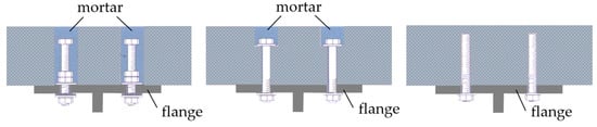
Figure 1.
Variations of headed shear stud connectors.
To some extent, preloading can also be applied to avoid this, but only to the solutions that use embedded nuts. Such a solution leads to ultimate resistances close to the resistance of welded studs, but with failure at a very low slip rate due to brittle failure of the bolts [23]. In addition to many other solutions for shear connectors described in [21], there are still some significant issues regarding the resistance and ductility of the proposed solutions that need to be addressed. Firstly, the resistance of bolted shear connectors cannot be calculated according to Eurocode 3. The additional resistance provided through the nut to flange friction and catenary effects in bolts themselves has been observed [23]. Secondly, propositions of Eurocode 4 [24] for the determination of shear connector ductility cannot be implemented for bolted shear connectors as they exhibit large slips before reaching ultimate strength and therefore need to be modified [25].
On the other hand, research of the shear connection solutions between thin cold-formed steel profiles and concrete slabs has not been extensive. First, shear connection experiments were conducted by Hanaor [8], where two types of connectors, embedded and dry, were tested. The embedded connectors used channel sections that were either connected to the beam section using 6 mm diameter screws or were welded to it. The obtained capacities were well above the values computed for fasteners in the cold-formed section using standards, pointing out that appropriate code provisions can be used in the absence of test data. Lakkavalli and You [11] conducted research on four shear transfer mechanisms to join cold-formed C-sections and concrete. Namely, these included surface bonds, prefabricated bent-up tabs, pre-drilled holes, and self-drilling screws. As expected, the surface bond specimens showed the lowest strength and stiffness, and the ones using bent-up tabs performed best at both strength and serviceability limit states. Of the three specimens with shear transfer enhancements, the ones using self-drilling screws resulted in the lowest strength increase. Later, Irwan et al. [26] conducted experiments on shear connections using bent-up triangular tabs. Wehbe et al. [27] examined the behaviour of composite beams of concrete and cold-formed steel using stand-off screws 8 mm in diameter as shear connectors. The results showed that such a solution is feasible for providing composite action, where composite beams with such connections can be designed for ductile flexural failure. Alhajri et al. [13] also used bolts of 12 mm diameter to ensure composite action between the lipped C-channels to Ferro cement slab. Such connection proved to have adequate strength to transfer forces from slab to slab beam section. Recently, Bamaga et al. [28] proposed three different demountable shear connection solutions between the cold-formed steel beam and concrete slab. Push-out tests of all three solutions showed extremely ductile behaviour with adequate strength capacity.
In addition to the above presented discrete shear connection solutions, innovative and promising shear connection solutions based on composite dowel rib connectors [29], as shown in Figure 2, have also been developed. Such type of shear connector in cold-formed composite beams is titled a continuous furring channel and has been presented in papers [30,31]. The shear connection solution comprised a continuous cold-formed furring shear connector connected through the metal deck on top of the steel beam using self-drilling fasteners, providing horizontal and vertical interlock between steel–concrete parts of the cross-section.
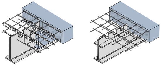
Figure 2.
Possible solutions with composite dowel rib connectors.
From all the above results, it is clear that cold-formed steel sections and concrete slabs can act compositely. However, the data on the behaviour and performance of cold-formed sections in composite construction are still lacking. In addition, as one of the main reasons for using composite sections and applying CFS built-up profiles are environmental and sustainability concerns, the preference in selecting the shear connection type should be given to the demountable solutions. The environmental impacts of the demountable and conventional shear connections can be quantified using the Lifecycle Assessment (LCA) method. The evaluation of environmental benefits obtained using the LCA method comparing demountable systems, promoting disassembly and reuse, to the conventional monolithic ones, destined for demolition and recycling, is presented [32]. As expected, the results are quite encouraging for the demountable shear connector solutions. In papers [33,34], research on such demountable headed shear stud connectors together with the use of ultra-high performance concrete was carried out. The proposed connectors show excellent ductility in comparison to traditional solutions. The push-out tests were conducted for various types of fasteners, changing their shape, diameter and bolt class, and the obtained results showed that the average slip was close to the value required by the EN 1994-1-1 [24]. However, when designing for demountability, it is necessary to keep in mind that one needs to limit the fasteners’ deformations during use and avoid the plastic response of the element to allow the reuse of parts of the structure. Some guidelines on this issue have been analysed for bolted joints with embedded nuts, considering the optimal ratio of beam span and depth of the demountable steel–concrete beam [35].
Developing a new type of shear connection requires experimental testing of the proposed connection type. Examples of the push-out tests on headed studs and composite dowel rib connectors are shown in Figure 3a,b, respectively.
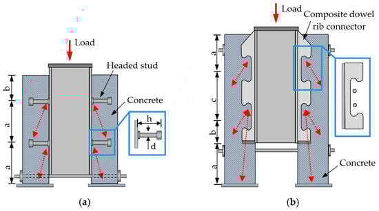
Figure 3.
Push-out tests examples: (a) headed studs; (b) composite dowel rib connectors.
The presented overview of the application of cold-formed sections in steel–concrete floor systems leads to some advantages such as [8]:
- The possibility of reducing overall slab depth by using lighter sections at closer spacing.
- Easy variation of the cross-section for irregular layouts.
- Freedom in the design of cross-sections, i.e., cold-formed sections are made from flat sheets and can be designed and manufactured to order. It is relatively easy to produce built-up members from sections and flat strips screwed or spot welded together.
- Flexibility in assembling the sections and attached components in the workshop and/or on-site.
- The technology for manufacturing cold-formed sections is available and straightforward in regions and countries where a large selection of hot-rolled profiles is not available on short order, particularly for small or medium size projects.
As in the case of the shear connection for the system’s overall behaviour, the connecting technique related to built-up cold-formed steel elements also has a vital aspect. A comprehensive experimental investigation on laser-welded connections based on lap-shear and tension tests is presented in [36]. In paper [37], a comparative resistance study was conducted of self-pierce riveting, resistance spot welding, and spot friction joining, identifying the resistance of spot welding as the most favourable option. Guenfoud et al. [38] tested welded specimens fabricated through one, two or four layers of thin steel sheets using the shear resistance and tension resistance of multi-layer arc spot welds.
2.2. Background to the LWT-FLOOR Structural System
Corrugated web beams represent a relatively new structural system that has emerged in the past two decades and was developed for various applications, i.e., the mainframes of single-storey steel buildings, secondary beams of multi-storey buildings, etc. Due to the thin webs, from 1.5 mm to 3 mm, corrugated web beams allow significant weight reduction compared to hot-rolled profiles or welded I-sections. The main benefits of this type of beam are that the corrugated webs increase the beam’s stability against local and lateral-torsional buckling and against web crippling, which may result in a more effective design from both technical and economic points of view.
The corrugated web does not participate in the longitudinal transfer of bending stresses. Therefore, in static terms, the corrugated web beam behaves like a lattice girder, in which the bending moments and applied forces are transferred only through the flanges. In contrast, the shear forces are transferred only through the diagonals and verticals of the lattice girder. Consequently, the girder’s flanges provide the flexural strength of the girder with no contribution from the corrugated web, which provides the girder’s shear capacity. Furthermore, the use of thinner webs without stiffeners results in lower material cost, with an estimated cost savings of 10–30% compared to conventionally fabricated sections and more than 30% compared to standard hot-rolled beams [39,40]. For instance, the buckling resistance of 1 mm thick sinusoidal corrugated sheet web corresponds to buckling resistance of a plain flat web of 12 mm thickness or even more.
In developed solutions from the literature, already available on the construction market, the flanges are flat plates welded to the sinusoidal web sheet, requiring a specific welding technology [41,42]. Almost all the research on this kind of girder was devoted to studying bending and shear capacity [43,44,45,46,47]. The dimensioning of corrugated web beams is ruled by Annex D of the EN 1993-1-5 [48,49,50].
The main benefits of build-up corrugated web elements using fixed supports have already been summarised and demonstrated through research investigation on such types of beams connected with screws [40,51,52], spot welding (SW) and Cold Metal Transfer (CMT) techniques [53,54,55]. CMT, mainly developed in the last years, is a new connection technology for building steel structures. Since the technical solution of such types of beams enables standardisation of design detailing and fabrication, both SW and CMT welding techniques are appropriate for application in automated fabrication. Therefore, besides the structural advantages of such a system, the potential for automated series fabrication of the new technological solutions is another great advantage.
In research [53,54,55], for the purpose of full-scale tests, two beam specimens were built-up applying the SW connection technique, i.e., CWB SW-1 and CWB SW-2. The components of the built-up beam specimens, which were 5157 mm long and 600 mm high, are shown in Figure 4.
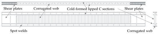
Figure 4.
Components of the SW built-up beams.
Compared to the solution with built-up beams using self-drilling screws [40,51,52], it can be seen that the beams connected using the spot weld technique possess higher stiffness and higher load-bearing capacity. The intermittent spot welding technique avoids the difficulties of traditional arc welding and specific technologies, thereby significantly increasing the fabrication speed. The numerical parametric research on the calibration and validation of the numerical models with additional experimental tests considering the influence of web openings have resulted in several papers [56,57,58]. These studies confirmed the excellent behaviour of SW built-up corrugated web beams.
2.3. LWT-FLOOR Project
Based on built-up cold corrugated web cold-formed steel beams and other previously mentioned facts, it is possible to develop the new composite floor system. LWT-FLOOR system represents such innovation that maximises the values of each building component and used materials. The system is being investigated within the research project LWT-FLOOR at the University of Zagreb, Faculty of Civil Engineering, Croatia.
The LWT-FLOOR project integrates state-of-the-art knowledge in new, fast and productive spot welding technology and innovative cold-formed steel–concrete composite solutions proposing a new construction method as a combination of built-up cold-formed steel members and cast-in-place concrete slab. This potentially cost-effective and sustainable floor system could offer vital benefits in a high degree of prefabrication, reusability, and suitability for larger spans.
In order to investigate and validate components and the proposed system, extensive experimental, numerical and theoretical research is planned. Within the research, a particular focus is given to spot welding connections and innovative types of shear connections with the possibility for demountability and the potential for reuse or recycling at the end of the product design life, which are additionally evaluated through the application of lifecycle analyses. Calibrated and validated numerical models based on experimental tests of the system and its components allow evaluation of the system suitability for larger spans. All the accumulated knowledge, including the support of probabilistic methods, will be the basis for further structural detailing and the possibility of mass production. Analyses and performance evaluation of the proposed floor system solution will be crucial for establishing the first analytical proposal for design recommendations of this new system within the European standards.
The proposed solution is partially made of steel, which is highly recyclable, and cold-formed products use a high percentage of recyclable steel [59]. Because of the design for demountability in one of the proposed shear connection types, the system has the potential for future reuse and recycling of products and components. Spot welding technology proved its economic effectiveness, compared to laser welding and conventional techniques, and sustainable performance in terms of consumption of welding materials, energy, workers’ health and safety issues, and elimination of inert shielding gases and particle emissions in the environment. The system will be durable under climate change effects and in an aggressive environment due to high protection from corrosion and the fact that all components are galvanised. It is easy to manipulate, transport and erect components of the system because of the reduced weight and safe connection technology. This can contribute to the safety of workers in the shops and building sites, cleaner activity on working sites, reduced energy consumption and lower emissions of greenhouse gasses. In the case of inner-city projects, construction speed and lack of on-site storage require a high level of prefabrication, which the proposed system can provide [60]. The proposed structural system falls into the category of adaptive building technology, following environmental and climate change requirements.
For the final applicability of the system in buildings, more knowledge about the behaviour in fire situations is required as well. Additionally, the system can also be applied in bridges; however, a detailed analysis of the fatigue behaviour is necessary.
Mentioned benefits of the system are investigated through experimental and numerical research with the support of probabilistic methods and lifecycle analyses by means of a holistic approach combining Lifecycle Assessment (LCA), Lifecycle Costs (LCC) and Lifecycle Performance (LCP) analyses.
The technical (mandatory O1 and O6) and scientific (O2 to O5) objectives with expected results (ER1 to ER6) of the LWT-FLOOR project are presented in Figure 5.
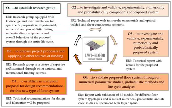
Figure 5.
Technical and scientific objectives of the LWT-FLOOR project.
Experimental research is divided into five phases. Experimental research of LWT-FLOOR system materials and spot welds between different cold-formed sheet thicknesses are performed in the first two phases. Because of the great importance of the shear connection between the steel and concrete part of the system, the third phase includes experimental tests on the shear connection.
The results from the push-out test are implemented in the numerical models for their calibration, and the obtained models are used as the input before the experimental bending test of large-scale specimens of the overall system are conducted.
In Figure 6, two proposed solutions for shear connections are presented.
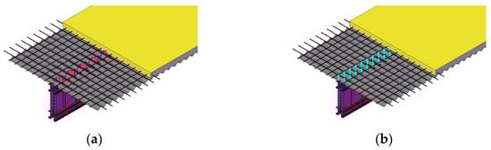
Figure 6.
Proposed solutions for shear connection: (a) composite dowel rib connectors; (b) demountable headed shear stud connectors.
The solution in Figure 6a is based on extending the corrugated web of steel beam to form a shear connection. The solution in Figure 6b uses demountable shear connectors, which should ensure the demountability of the floor system at the end of its service life.
Within phases 4 and 5 of the experimental research full-scale LWT-FLOOR system is tested. The span of tested elements are approximately 6 m, corresponding to typical spans of floor systems in multi-storey buildings. In the first phase of experimental research, to understand the behaviour of corrugated built-up cold-formed girders without and with web openings, tests of the girders without concrete slab are conducted, Figure 7.
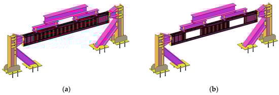
Figure 7.
Built-up corrugated web girder: (a) without web openings; (b) with web openings.
Based on obtained results for optimal shear connection and steel girder solution, the experimental tests of the composite LWT-FLOOR system are performed. Figure 8 shows the proposed test set-up for the LWT-FLOOR beam.
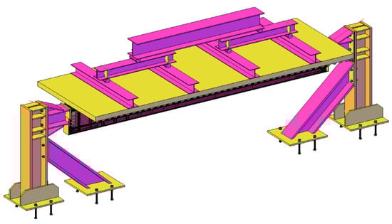
Figure 8.
Proposal for test set-up for LWT-FLOOR system.
Based on calibrated numerical models, the numerical part of the research allows parametric research of the proposed solution. In the first phase, the numerical models of shear connection in combination with probabilistic analyses provide a selection of the optimal solution of the shear connection. The second phase of numerical research is numerical modelling of built-up corrugated web beams without and with web openings. Calibrated numerical models are the base for parametric studies to find the optimal solution for larger spans and different configurations of web openings.
Finally, calibration of a numerical model for composite LWT-FLOOR system and numerical parametric studies in combination with probabilistic analyses ensure the validation of the suitability of such system for larger spans and determine optimal dimensions of particular system components by taking into account different configurations of the shear connection and boundary conditions.
Based on probabilistic analyses and lifecycle analyses, the analytical proposal is be evaluated for analysed types of shear connections, steel girders with and without web openings, and composite LWT-FLOOR systems without and with web openings.
2.4. Analytical Model
Since cold-formed steel cross-sections are usually class 3 and 4, their plastic resistance in bending cannot be achieved. However, plastic resistance can be achieved in a composite beam with a full shear connection, but the cross-section’s neutral axis position must be considered.
The neutral axis can be located in the concrete flange, at the interface between the concrete flange and the steel beam, or within the steel beam. Within steel beam means either in the flange or in the web of the steel beam.
Thus, taking into account the position of the neutral axis in the cross-section of the composite beam, and when the neutral axis is located in the concrete flange or at the interface between the concrete flange and the steel beam, the steel cross-section will be completely or mainly in tension. Therefore, the bending resistance of the composite cross-sections, which consists of either class 3 or class 4 steel cross-section, can be calculated in the same way as the resistance for the class 1 or class 2 cross-section.
Investigated cross-section geometry is presented in Figure 9. The thickness of the concrete flange is 90 mm, and its effective width is 1000 mm with the concrete class C25/30. Built-up cold-formed steel beam consisted of four C120 sections with a thickness of 2.5 mm, flange width of 47 mm and height of 120 mm, and corrugated web and shear plates of 1.2 mm thickness with an overall height of 400 mm. All steel parts were considered to be made of steel grade S350. The span of the beam is 6 m. For the presented geometry and in the case of a full shear connection, the plastic neutral axis is located in a concrete flange.
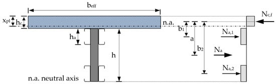
Figure 9.
Cross-section of the analysed LWT-FLOOR beam.
The plastic bending resistance Mpl,Rd in the case of full shear connection is calculated using Equations (1) and (2) or Equations (3) and (4), which depends on what part of the cross-section is considered, i.e., the concrete or the steel part, see Figure 9.
where: Nc,f is the design value of the normal compressive force in the concrete flange with full shear connection, a is the distance according to Figure 9, beff is the total effective width of concrete flange, xpl is the distance of the neutral axis from the upper edge of the concrete slab, fcd is the design value of concrete compressive strength, h is the depth of the corrugated web structural steel section, hc is the thickness of the concrete flange, Aa is the cross-sectional area of the cold-formed structural steel C-section, fyd is the design value of the yield strength of structural steel, b1 and b2 are the centroids distances according to Figure 9, ha is the depth of the cold-formed structural steel C-section.
In the case of partial shear connection, the bending resistance MRd in the case of plastic structural steel cross-section can be calculated using Equation (5) according to EN 1994-1-1 [24].
where: Mpl,a,Rd is the plastic bending resistance of the structural steel section, and ƞ is the degree of shear connection calculated according to Equation (6).
where: n is the number of shear connector pairs and PRd,min is the minimum design value of the shear resistance of a single connector. Bolts with 12 mm diameter and 8.8 steel grade were considered in this paper for calculation of PRd,min.
When using cold-formed corrugated web structural steel cross-sections, the following modified expression given in Equation (7) is proposed for the calculation of the composite cross-section bending resistance:
where: Mel,a,Rd is the elastic bending resistance of the cold-formed corrugated web structural steel cross-section.
According to Equation (7), the bending resistance of the analysed system will be equal to the elastic bending resistance of the cold-formed corrugated web structural steel cross-section Mel,a,Rd when the degree of shear connection ƞ = 0. In the case of full shear connection, ƞ = 1, the plastic bending resistance of composite cross-section, Mpl,Rd can be achieved.
Calculated bending resistance for full shear connection and solutions with the shear connectors distance of 300 mm (ƞ = 1) and 600 mm (ƞ = 0.55) were compared with the results of FE simulations in Section 3.
2.5. Numerical Model
2.5.1. Boundary Conditions and Finite Element Mesh
The numerical FE model is based on a static system with four concentrated forces as load, as presented in Figure 10. Figure 10a shows the static system of the beam with pinned supports, while Figure 10b shows an alternative solution with fixed supports. Because of the system’s nonlinear behaviour and redistribution of moments at the supports, the analytically calculated bending resistance is compared with the resistance of the composite cross-section in the beam midspan. The bending moment from FE models is assumed to be based on a simply supported beam, Figure 10a. This assumption means that the bending moment in the beam midspan is equal to 4F multiplied by 0.75 for both cases, pinned and fixed solution.
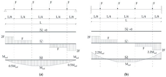
Figure 10.
Static systems of analysed solutions: (a) pinned supported beam; (b) fixed supported beam.
The model of the analysed composite beam in Abaqus/CAE software [61] is presented in Figure 11. Figure 11 also shows two analysed solutions of spot weld configurations, i.e., solutions with 2 and 3 spot welds (SW2 and SW3, respectively).
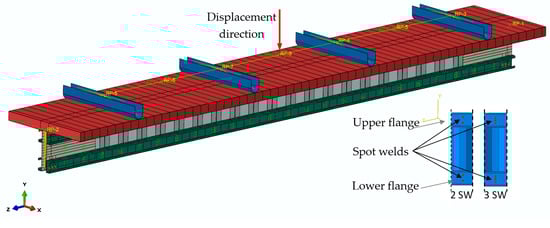
Figure 11.
FE model in ABAQUS/CAE with the definition of 2 SW and 3 SW configurations.
According to [56,58], the beam loading was defined as a vertical displacement in a set of multipoint constraints (MPC) that forms a leverage system to transmit the deflection to the four loading points, see Figure 11. A kinematic coupling constraint defined the link between the control points and the pressure elements for all DOFs. RB3D2 elements were used as a rigid body for load transfer and multipoint constraint beam (MPC beam) for DOF coupling between groups of specified nodes. The total force, 4F, is obtained by monitoring the reaction force on the node where vertical displacement is applied.
Due to the complicated geometry and multiple contact interactions between different components, the “explicit” solving method was utilised to avoid the numerical convergence difficulties, which is often encountered in the “implicit” solving method. The loading speed is defined by ramping up the velocity smoothly over the analysis step. To increase the speed of performed analyses, loading velocity is increased, ensuring minimal inertia effects. This is ensured by maintaining kinetic energy at a small value throughout the analyses (mainly below 5% of all energy) and by limiting loading velocity to less than 1% of the wave speed of the used materials. However, several drops in the resulting curves of moments and forces can be observed. The authors believe that such drops result from spot weld failures and buckling of the steel beam components.
General contact with the following parameters between all elements in the model was used, i.e., normal direction—hard contact, transverse direction—a friction coefficient of 0.1 and separation was allowed after the general contact takes place.
Geometric and material nonlinear analyses, including the effects of initial imperfections (GMNIA), were performed. The numerical modelling consists of two steps. In the first step, the initial imperfections are modelled by performing static analysis, which results in desired imperfection shape—with the magnitude of the shell thickness. In the second step, the dynamic, explicit analysis is used to run the load-displacement analysis of the beam, including imperfect geometry obtained from previous analysis and all contacts and material nonlinearities.
In order to carry out dynamic analysis, the density of the material needs to be specified. The density of steel components is set to 7850 kg/m3, while the density of concrete is 2400 kg/m3.
Each part of the built-up steel beam was defined as a 3D shell element S4R, while solid C3D8R elements were used to model concrete flange. The FE mesh density is 20 mm for steel sections and 30 mm for the concrete flange.
2.5.2. Material Model for Spot Welds, Steel Beam and Headed Shear Studs
The material and spot weld properties from the research of Ungureanu et al. [53,54] were used for corrugated beam components and their assembly with spot welds.
The spot welds (SW) between different parts of the built-up beams were defined in function of the tensile-shear tests of the simple specimens according to [58]. Attachment points were defined on each part where SW was applied. The connection between the attachment points was defined using Point-Based Fasteners with the connector response [61] of the SW initially calibrated from the tensile-shear test results from [53,54]. The connector was considered using the elasticity, plasticity, damage and failure parameters. Bushing connector elements were used to model the SW. This type of element provides a connection between two nodes that allows independent behaviour in three local Cartesian directions that follow the system at both nodes and that allows different behaviour in two flexural rotations and one torsional rotation [61].
In order to obtain realistic results from the finite element nonlinear analyses, plastic strains were included in the material definition, according to EN 1993-1-5, Annex C [45]. The measured stress–strain curves based on tensile tests on coupons cut from the cross-section of component elements were included in the model. The static engineering stress–strain curves obtained from tensile coupon tests were converted to true stress vs. logarithmic true plastic strain curves in the plastic analysis. The true stress σtrue and true plastic strain εtrue were calculated using Equations (8) and (9) as follows:
In order to include plasticity, the stress–strain points past yield must be input in the form of true stress and logarithmic plastic strain. The logarithmic plastic strain was calculated with Equation (10) as follows:
where σtrue/E is the elastic strain and E is Young’s modulus.
The shear connection is taken into account using three different solutions, i.e., full tie connection between concrete flange and steel beam, shear connectors modelled by wire elements spaced at 300 mm (degree of shear connection is 1) and 600 mm (degree of shear connection is 0.55). The connectors section was defined using the bushing connection type with defined elasticity, plasticity damage and failure parameters based on calculated resistances of the analysed shear stud connectors, i.e., bolts with 12 mm diameter and 8.8 steel grade. After obtaining experimental results, more detailed definitions of shear connectors will be considered. Examples of shear connectors definitions with local interactions and damage initiation can be found in the literature [62,63,64].
2.5.3. Material Model for Concrete
The concrete damaged plasticity model (CDP) was used to model the concrete slab. This model is primarily based on two main failure mechanisms of tensile cracking and compressive crushing of concrete [64]. The yield (or failure) surface evolution is controlled by two hardening variables linked to failure mechanisms under tension and compression loading, respectively [61]. This paper took the dilation angle as 40° according to [64], while default values were assumed for all other plasticity parameters.
The modulus of elasticity of concrete, Ecm, was calculated according to EN 1992-1-1: 2004 [65] as:
where, fcm is the mean value of concrete cylinder compressive strength, and fck is the characteristic compressive cylinder strength of concrete at 28 days.
In EN 1992-1-1 [65] the relationship between compressive stress, σc and shortening strain, εc for short term uniaxial loading is described by the Equation (13):
with
where ԑc is compressive strain, ԑc1 is the compressive strain in the concrete at the peak stress fc, εc1 = 0.7∙fcm0.31 ≤ 2.8 × 10⁻³. Equation (13) is valid for compressive strain region 0 < |εc| < |εcu1| where εcu1 is the nominal ultimate strain. The strain at peak stress εc1 = 2.25 × 10⁻³, and nominal ultimate strain εcu1 = 3.5 × 10⁻³ were adopted from EN 1992-1-1 [65].
The stiffness degradation dc on account of crushing of concrete was calculated with Equation (16):
Stress–strain behaviour of plain concrete in uniaxial compression defined in the EN 1992-1-1 [65] with concrete stiffness degradation in compression dc is presented in Figure 12.
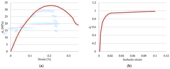
Figure 12.
Parameters of concrete in compression: (a) stress–strain relation of concrete for structural analysis based on EN 1992-1-1; (b) concrete stiffness degradation in compression.
As presented with Equation (13) and Figure 12, the plasticity curve in EN 1992-1-1 is defined only up to nominal ultimate strain εcu1. In cases when high crushing strains are expected, the extensions of the Eurocode model can be used as presented in the paper [23]:
where μ = (εc − εcuD)/(εcuE − εcuD) is relative coordinate between points D–E and β = fcm/fcu1. Point D is defined as εcuD = εcu1 and fcuD = fcu1 = σc(εcu1) from Equation (13). Point E is the end of the sinusoidal descending part at strain εcuE with concrete strength reduced to fcuE by factor α = fcm/fcuE. The linear descending part (residual branch) ends in point F at strain εcuF with the final residual strength of concrete fcuF. In the paper [23] strain εcuF = 0.10 was chosen large enough not to be achieved in the analyses. Compression plasticity curve defined dependent on inelastic strain assuming that the concrete acts elastically up to 0.4 × fcm is presented in Figure 13.
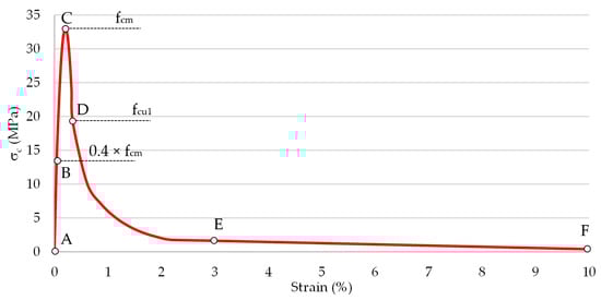
Figure 13.
Parameters of concrete in compression, an extension of EN 1992-1-1 model.
The extension of the EN 1992-1-1 model does not change the presented models’ results, which means that the compression strains are below strain εcu1.
The tension plasticity curve is defined as the function of cracking strain and tensile stress. Tensile stress increases linearly along with modulus of elasticity, up to the peak value ft. In this paper, the post-failure tensile behaviour is defined by using the exponential function proposed by Cornelissen et al. [66]:
where w is the crack opening displacement, wc is the crack opening displacement at which stress can no longer be transferred wc = 5.14 × Gf/ft, is a material constant and = 3.0 for normal density concrete, is a material constant and = 6.93 for normal density concrete.
The value of fracture energy, the energy required to develop a unit area of a crack in (N/mm), is [67,68]:
The degradation in tension dt was calculated with Equation (21):
The tensile stress versus cracking displacement relation using Equation (18) and tensile damage versus cracking displacement relation, Equation (21), are shown in Figure 14.
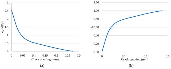
Figure 14.
Parameters of concrete in tension: (a) tensile stress versus cracking displacement; (b) tensile damage versus cracking displacement.
3. Results and Discussion
Figure 15 shows analytically calculated bending moment resistance based on Equations (5) and (7) concerning the degree of shear connection for beam geometry from Section 2.4.
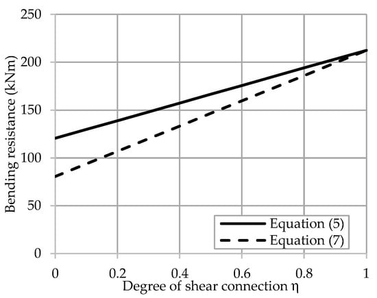
Figure 15.
Analytically calculated bending moment resistance based on Equations (5) and (7) concerning the degree of shear connection.
Results of the numerical study are divided based on the beam supports definition. The results of the beam model with pinned supports and beam model with fixed supports are presented in the following subsections and compared with analytically obtained results from Figure 15.
3.1. Beam with Pinned Supports
Figure 16 shows the differences in end slip between three analysed solutions depending on the shear connection, i.e., solutions with fully tied concrete flange to the steel beam and solutions with shear connectors longitudinally spaced at 300 mm and 600 mm. The 300 mm shear connector spacing represents a full shear connection with the degree of shear connection around 1. In contrast, the 600 mm shear connector spacing represents a partial shear connection with the degree of the shear connection of 0.55. Figure 16a shows that the end slip is completely prevented, while on the other hand, in Figure 16b,c the existence of some end slip is observed.
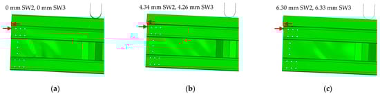
Figure 16.
Differences in end slip between three analysed solutions of pinned beam: (a) full tie shear connection; (b) shear connectors spaced at 300 mm; (c) shear connectors spaced at 600 mm.
The bending resistance of the beam in the cases of fully tied shear connection and analysed spot weld solutions, i.e., SW2 and SW3, are presented in Figure 17. Both curves in Figure 17a,b shows that the numerically obtained bending resistance is higher than the analytically calculated bending resistance presented with a dashed horizontal line.
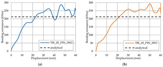
Figure 17.
Bending resistance of the pinned beam for a fully tied shear connection: (a) SW2; (b) SW3.
In the case of beams with shear connectors longitudinally spaced at 300 mm, the reduced stiffness and bending capacity are observed compared to the full tie shear connection results, as shown in Figure 18. Figure 18a shows the bending resistance of simply supported beam in the cases when shear connectors are spaced at 300 mm with SW2 spot weld configuration while Figure 18b shows bending resistance when SW3 spot weld configuration is used.
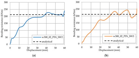
Figure 18.
Bending resistance of the pinned beam for shear connectors spaced at 300 mm: (a) SW2; (b) SW3.
In the case when shear connectors are spaced at 600 mm, similar results are obtained as the ones when the spacing of 300 mm is applied. The obtained results are presented with curves in Figure 19. From the curves in Figure 17, Figure 18 and Figure 19, it can be observed that the solutions with SW2 and SW3 spot weld configurations are in good correlation. The number of SW does not govern the bending capacity of pinned beam solutions to a great extent.
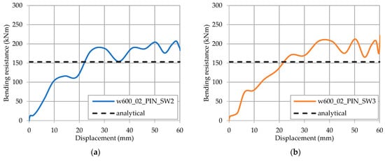
Figure 19.
Bending resistance of the pinned beam for shear connectors spaced at 600 mm: (a) SW2; (b) SW3.
3.2. Beam with Fixed Supports
Figure 20 shows end slip behaviour in the case of fixed end supports between three analysed solutions of shear connection. From the comparison with the solutions of the beam with pined supports, it can be observed that slip is prevented in the fixed beam, but some separation between the concrete flange and steel cross-section exists.
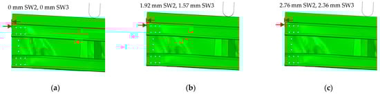
Figure 20.
Differences in end slip between three analysed solutions of fixed beam: (a) full tie shear connection; (b) shear connectors spaced at 300 mm; (c) shear connectors spaced at 600 mm.
In the case of fixed end supports, the stiffness of the beam is generally increased. The behaviour in the cases of different degrees of shear connections is similar to the pinned solution. Figure 21 shows the bending resistance of the beam with fixed supports and a full tie shear connection. Both curves in Figure 21a,b shows that the numerically obtained bending resistance is higher than the analytically calculated bending resistance presented with a dashed horizontal line.
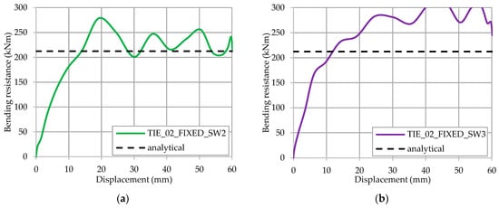
Figure 21.
Bending resistance of the fixed beam for a fully tied shear connection: (a) SW2; (b) SW3.
Figure 22 shows the results in the 300 mm spacing between shear connectors, and again, bending resistance is higher than analytically calculated resistance. Contrary to the pinned beam case, the solution with SW3 configuration increases the bending capacity.
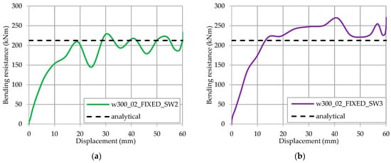
Figure 22.
Bending resistance of the fixed beam for shear connectors spaced at 300 mm: (a) SW2; (b) SW3.
In the case of shear connectors being spaced at 600 mm, the results are presented in Figure 23. As was the case in the previous solutions, the bending resistance is higher than the analytically calculated resistance. In the cases of shear connectors being spaced at 300 mm and 600 mm, the solutions with SW3 and SW2 are different, which means that this solution with fixed supports is governed by the number of SW, which was not the case for the pinned beam solution.
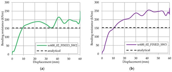
Figure 23.
Bending resistance of the fixed beam for shear connectors spaced at 600 mm: (a) SW2; (b) SW3.
3.3. Comparison of the Pinned and Fixed Solution
Figure 24, Figure 25 and Figure 26 show comparisons of the force/displacement diagrams for the solutions with SW2 and SW3 configurations. These comparisons clearly show that SW3 solutions have a small influence compared to SW2 for the pinned solution of the beam. Additionally, the stiffness and decrease of capacity are also evident from fully tied to partial shear connection. If we compare pinned and fixed solutions of beam end supports, we can conclude the following. The stiffness and the bending capacity are increased from pinned to fixed solutions. Such behaviour, as already discussed, can also be captured from the partial to fully tied shear connection.
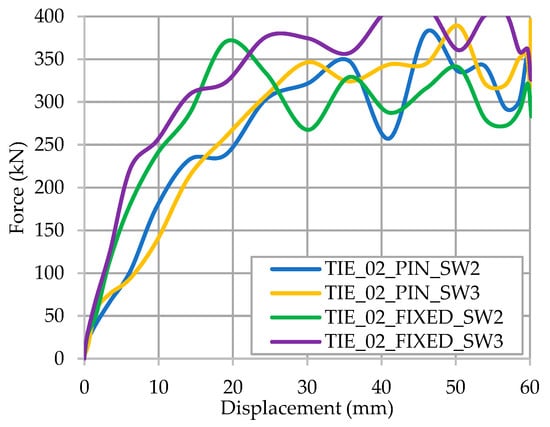
Figure 24.
Force/displacement diagrams for 2 SW and 3 SW configurations of the pinned and fixed beam with full tie shear connection.
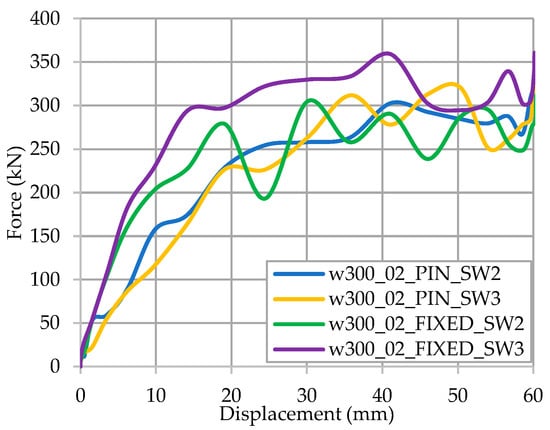
Figure 25.
Force/displacement diagrams for 2 SW and 3 SW configurations of the pinned and fixed beam with shear connectors spaced at 300 mm.
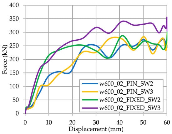
Figure 26.
Force/displacement diagrams for 2 SW and 3 SW configurations of the pinned and fixed beam with shear connectors spaced at 600 mm.
4. Conclusions
Due to their efficiency, steel–concrete structural systems are increasingly used in the construction industry and are still the subject of intensive research. This results from their efficient material usage, especially with cold-formed built-up sections and innovative shear connections. The popularity of such systems arose from their flexibility, adaptability, and capacity for dismantling and reuse. This paper summarises an overview of cold-formed steel–concrete composite floor systems developments. Additionally, it gives the background, planned activities and recent results related to developing the new innovative solution within research project LWT-FLOOR, which is ongoing at the University of Zagreb, Faculty of Civil Engineering, Croatia. The LWT-FLOOR project investigates innovative lightweight solutions that can result in new sustainable and resilient construction products due to the holistic design approach integrating manufacturing, operation, maintenance and reuse stages up to the end-of-life.
From the literature survey, the following aspects can be highlighted.
Shear connection mechanisms and mechanisms of the connections between steel elements in built-up cold-formed steel beams greatly influence the behaviour of composite floor systems. These mechanisms are of vital interest to optimise components and produce more economical and efficient floor systems. Integrating the floor system related to its connection to the rest of the structure is another important issue. Simple and effective connections of the floor system will result in carrying the vertical load and providing a shear diaphragm, which is crucial for the performance of the overall structure.
The presented LWT-FLOOR project integrates state-of-the-art knowledge in a new and productive spot welding technology and innovative cold-formed steel–concrete composite solutions to develop a cost-effective and competitive floor system. The LWT-FLOOR system can give vital benefits in terms of a high degree of prefabrication, reusability and suitability for larger spans to maximise the values of building components and materials.
The proposed analytical solution for bending resistance of composite cross-section is based on the elastic bending resistance of steel beams. The numerical parametric FE analyses show that the bending capacity of the LWT-FLOOR beams made of cold-formed steel and the cast-in-place concrete slab can be compared with analytical results.
Results of the parametric FE study show that the bending capacity of the LWT-FLOOR beams made of cold-formed steel and the cast-in-place concrete slab is affected by the resistance of the cold-formed steel components and by the degree of shear connection. In the case of a fixed beam solution, the resistance of the LWT-FLOOR beam is governed by the resistance of the steel beam, i.e., spot welds. In the cases with pinned beam solution, the results show that the resistance of the LWT-FLOOR beam is governed by the degree of shear connection. At the same time, the increased number of SW from two to three between channel flanges and corrugated web does not influence the beam resistance. This means that the beam resistance in the pinned solution is rather more affected by the stability of the cold-formed steel components than the number of spot welds, with a significant influence on the type and degree of shear connection.
Based on previous studies on steel built-up corrugated web beams, it is observed that the resistance is dependent on the thicknesses of the corrugated web and the thickness of the shear plate. Therefore, such solutions will be investigated in the extension of this research.
Author Contributions
Conceptualisation, I.L.; methodology, I.L. and I.Ć.; software, I.L. and A.R.; validation, I.L., I.Ć. and M.B.; formal analysis, A.R.; investigation, I.L., I.Ć. and A.R.; resources, I.L., I.Ć. and M.B.; data curation, I.L., I.Ć. and A.R.; writing—original draft preparation, I.L.; writing—review and editing, all authors; visualisation, I.L. and A.R.; supervision, I.L., I.Ć. and M.B.; project administration, I.L., I.Ć. and A.R.; funding acquisition, I.L. All authors have read and agreed to the published version of the manuscript.
Funding
This research was partially funded by the Croatian Science Foundation, grant number UIP-2020-02-2964 (LWT-FLOOR project—Innovative lightweight cold-formed steel–concrete composite floor system), project leader: Ivan Lukačević.
Institutional Review Board Statement
Not applicable.
Informed Consent Statement
Not applicable.
Data Availability Statement
The data presented in this study are available on request from the corresponding author.
Conflicts of Interest
The authors declare no conflict of interest. The funders had no role in the design of the study; in the collection, analyses, or interpretation of data; in the writing of the manuscript, or in the decision to publish the results.
References
- Dujmović, D.; Androić, B.; Lukačević, I. Composite Structures According to Eurocode 4: Worked Examples; John Wiley and Sons: Berlin, Germany, 2015. [Google Scholar]
- Ahmed, I.M.; Tsavdaridis, K.D. The evolution of composite flooring systems: Applications, testing, modelling and eurocode design approaches. J. Constr. Steel Res. 2019, 155, 286–300. [Google Scholar] [CrossRef]
- Androić, B.; Dujmović, D.; Lukačević, I. Design of Composite Structures According to Eurocode 4; IA Projektiranje: Zagreb, Croatia, 2012. [Google Scholar]
- Hicks, S. EN 1994-Eurocode 4: Design of composite steel and concrete structures-Composite slabs. In Proceedings of the EUROCODES Background and Applications, “Dissemination of Information for Training” Workshop, Brussels, Belgium, 18–20 February 2008; pp. 1–24. [Google Scholar]
- Nguyen, R.P. Thin-Walled, Cold-Formed Steel Composite Beams. J. Struct. Eng. 1991, 117, 2936–2952. [Google Scholar] [CrossRef]
- Anwar Hossain, K.M. Designing thin-walled composite-filled beams. Proc. Inst. Civ. Eng. Struct. Build. 2005, 158, 267–278. [Google Scholar] [CrossRef]
- Abdel-Sayed, G. Composite Cold-Formed Steel-Concrete Structural System. In Proceedings of the 6th International Specialty Conference on Cold-Formed Steel Structures, St. Louis, MO, USA, 16–17 November 1982; University of Missouri: Rolla, MO, USA, 1982; pp. 485–510. [Google Scholar]
- Hanaor, A. Tests of composite beams with cold-formed sections. J. Constr. Steel Res. 2000, 54, 245–264. [Google Scholar] [CrossRef]
- Přivřelová, V. Modelling of Composite Steel and Concrete Beam with the Lightweight Concrete Slab. Int. J. Civ. Environ. Eng. 2014, 8, 1130–1134. [Google Scholar] [CrossRef]
- Zhou, X.; He, Y.; Jia, Z.; Nie, S. Experimental study on vibration behavior of cold-form steel concrete composite floor. Adv. Steel Constr. 2011, 7, 302–312. [Google Scholar]
- Lakkavalli, B.S.; Liu, Y. Experimental study of composite cold-formed steel C-section floor joists. J. Constr. Steel Res. 2006, 62, 995–1006. [Google Scholar] [CrossRef]
- Hsu, C.-T.T.; Punurai, S.; Punurai, W.; Majdi, Y. New composite beams having cold-formed steel joists and concrete slab. Eng. Struct. 2014, 71, 187–200. [Google Scholar] [CrossRef]
- Alhajri, T.M.; Tahir, M.M.; Azimi, M.; Mirza, J.; Lawan, M.M.; Alenezi, K.K.; Ragaee, M.B. Behavior of pre-cast U-Shaped Composite Beam integrating cold-formed steel with ferro-cement slab. Thin Walled Struct. 2016, 102, 18–29. [Google Scholar] [CrossRef]
- Saggaff, A.; Tahir, M.M.; Azimi, M.; Alhajri, T.M. Structural aspects of cold-formed steel section designed as U-shape composite beam. AIP Conf. Proc. 2017, 1903, 020025. [Google Scholar]
- Khadavi; Tahir, M.M. Prediction on flexural strength of encased composite beam with cold-formed steel section. AIP Conf. Proc. 2017, 1903, 020016. [Google Scholar]
- Salih, M.N.A.; Md Tahir, M.; Mohammad, S.; Ahmad, Y.; Sulaiman, A.; Shek, P.N.; Abraham, A.; Firdaus, M.; Aminuddin, K.M. Khadavi Experimental study on flexural behaviour of partially encased cold-formed steel composite beams using rebar as shear connector. IOP Conf. Ser. Mater. Sci. Eng. 2019, 513, 012038. [Google Scholar] [CrossRef]
- de Seixas Leal, L.A.A.; de Miranda Batista, E. Composite floor system with CFS trussed beams, concrete slab and innovative shear connectors. Rev. Esc. Minas 2020, 73, 23–31. [Google Scholar]
- de Seixas Leal, L.A.A.; de Miranda Batista, E. Composite floor system with cold-formed trussed beams and prefabricated concrete slab. Steel Constr. 2020, 13, 12–21. [Google Scholar] [CrossRef]
- Tian, L.M.; Kou, Y.F.; Hao, J.P.; Zhao, L.W. Flexural performance of a lightweight composite floor comprising cold-formed steel trusses and a composite mortar slab. Thin-Walled Struct. 2019, 144, 106361. [Google Scholar] [CrossRef]
- Liu, J.; Zhao, Y.; Chen, Y.F.; Xu, S.; Yang, Y. Flexural behavior of rebar truss stiffened cold-formed U-shaped steel-concrete composite beams. J. Constr. Steel Res. 2018, 150, 175–185. [Google Scholar] [CrossRef]
- Jakovljević, I.; Spremić, M.; Marković, Z. Demountable composite steel-concrete floors: A state-of-the-art review. J. Croat. Assoc. Civ. Eng. 2021, 73, 249–263. [Google Scholar] [CrossRef]
- Lam, D.; Dai, X.; Ashour, A.; Rehman, N. Recent research on composite beams with demountable shear connectors. Steel Constr. 2017, 10, 125–134. [Google Scholar] [CrossRef]
- Pavlović, M.; Marković, Z.; Veljković, M.; Buđevac, D. Bolted shear connectors vs. headed studs behaviour in push-out tests. J. Constr. Steel Res. 2013, 88, 134–149. [Google Scholar] [CrossRef]
- EN 1994-1-1: Eurocode 4: Design of Composite Steel and Concrete Structures—Part 1-1: General Rules and Rules for Buildings; CEN: Brussels, Belgium, 2004.
- Kozma, A.; Odenbreit, C.; Braun, M.V.; Veljkovic, M.; Nijgh, M.P. Push-out tests on demountable shear connectors of steel-concrete composite structures. Structures 2019, 21, 45–54. [Google Scholar] [CrossRef]
- Irwan, J.M.; Hanizah, A.H.; Azmi, I. Test of shear transfer enhancement in symmetric cold-formed steel–concrete composite beams. J. Constr. Steel Res. 2009, 65, 2087–2098. [Google Scholar] [CrossRef]
- Wehbe, N.; Bahmani, P.; Wehbe, A. Behavior of Concrete/Cold Formed Steel Composite Beams: Experimental Development of a Novel Structural System. Int. J. Concr. Struct. Mater. 2013, 7, 51–59. [Google Scholar] [CrossRef]
- Bamaga, S.O.; Tahir, M.M.; Tan, C.S.; Shek, P.N.; Aghlara, R. Push-out tests on three innovative shear connectors for composite cold-formed steel concrete beams. Constr. Build. Mater. 2019, 223, 288–298. [Google Scholar] [CrossRef]
- Kopp, M.; Wolters, K.; Claßen, M.; Hegger, J.; Gündel, M.; Gallwoszus, J.; Heinemeyer, S.; Feldmann, M. Composite dowels as shear connectors for composite beams—Background to the design concept for static loading. J. Constr. Steel Res. 2018, 147, 488–503. [Google Scholar] [CrossRef]
- Majdi, Y.; Hsu, C.T.T.; Punurai, S. Local bond-slip behavior between cold-formed metal and concrete. Eng. Struct. 2014, 69, 271–284. [Google Scholar] [CrossRef]
- Majdi, Y.; Hsu, C.T.T.; Zarei, M. Finite element analysis of new composite floors having cold-formed steel and concrete slab. Eng. Struct. 2014, 77, 65–83. [Google Scholar] [CrossRef]
- Brambilla, G.; Lavagna, M.; Vasdravellis, G.; Castiglioni, C.A. Environmental benefits arising from demountable steel-concrete composite floor systems in buildings. Resour. Conserv. Recycl. 2019, 141, 133–142. [Google Scholar] [CrossRef]
- Wang, J.-Y.; Guo, J.-Y.; Jia, L.-J.; Chen, S.-M.; Dong, Y. Push-out tests of demountable headed stud shear connectors in steel-UHPC composite structures. Compos. Struct. 2017, 170, 69–79. [Google Scholar] [CrossRef]
- Yang, F.; Liu, Y.; Jiang, Z.; Xin, H. Shear performance of a novel demountable steel-concrete bolted connector under static push-out tests. Eng. Struct. 2018, 160, 133–146. [Google Scholar] [CrossRef]
- Girão Coelho, A.M.; Lawson, R.M.; Aggelopoulos, E.S. Optimum use of composite structures for demountable construction. Structures 2019, 20, 116–133. [Google Scholar] [CrossRef]
- Landolfo, R.; Mammana, O.; Portioli, F.; Di Lorenzo, G.; Guerrieri, M.R. Laser welded built-up cold-formed steel beams: Experimental investigations. Thin-Walled Struct. 2008, 46, 781–791. [Google Scholar] [CrossRef]
- Briskham, P.; Blundell, N.; Han, L.; Hewitt, R.; Young, K.; Boomer, D. Comparison of Self-Pierce Riveting, Resistance Spot Welding and Spot Friction Joining for Aluminium Automotive Sheet. In Proceedings of the SAE 2006 World Congress & Exhibition, Detroit, MI, USA, 3–6 April 2006; p. 15. [Google Scholar]
- Guenfoud, N.; Tremblay, R.; Rogers, C.A. Arc-Spot Welds for Multi-Overlap Roof Deck Panels. In Proceedings of the Twentieth International Specialty Conference on Cold-Formed Steel Structures, St. Louis, MO, USA, 3–4 November 2010; pp. 535–549. [Google Scholar]
- Ungureanu, V.; Dubina, D. Influence of Corrugation Depth on Lateral Stability of Cold-Formed Steel Beams of Corrugated Webs. Acta Mech. Autom. 2016, 10, 104–111. [Google Scholar] [CrossRef][Green Version]
- Dubina, D.; Ungureanu, V.; Gîlia, L. Experimental investigations of cold-formed steel beams of corrugated web and built-up section for flanges. Thin-Walled Struct. 2015, 90, 159–170. [Google Scholar] [CrossRef]
- Hamada, M.; Nakayama, K.; Kakihara, M.; Saloh, K.; Ohtake, F. Development of welded I-beam with corrugated web. Sumitomo Search 1984, 29, 75–90. [Google Scholar]
- Zeman & Co GmbH. Corrugated Web Beam, Technical Document; Zeman & Co GmbH: Wien, Austria, 1993. [Google Scholar]
- EN1993-1-1 Eurocode 3: Design of Steel Structures—Part 1-1: General Rules and Rules for Buildings; Including; CEN: Brussels, Belgium, 2005.
- EN1993-1-3 Eurocode 3: Design of Steel Structures. Part 1-3: General Rules. Supplementary Rules for Cold-Formed Thin Gauge Members and Sheeting; CEN: Brussels, Belgium, 2006.
- EN1993-1-5 Eurocode 3: Design of Steel Structures—Part 1-5: Plated Structural Elements; CEN: Brussels, Belgium, 2006.
- Elgaaly, M.; Dagher, H. Beams and Girders with Corrugated Webs. In Proceedings of the SSRC Annual Technical Session, St. Louis, MO, USA, 10–11 April 1990; pp. 37–53. [Google Scholar]
- Lindner, J. Lateral-torsional buckling of beams with trapezoidally corrugated webs. In Proceedings of the 4th International Colloquium on Stability of Steel Structures, Budapest, Hungary, 25–27 April 1990; pp. 79–82. [Google Scholar]
- Moon, J.; Yi, J.-W.; Choi, B.H.; Lee, H.-E. Lateral–torsional buckling of I-girder with corrugated webs under uniform bending. Thin-Walled Struct. 2009, 47, 21–30. [Google Scholar] [CrossRef]
- Pasternak, H.; Robra, J.; Kubieniec, G. New proposals for EN 1993-1-5, Annex D: Plate girders with corrugated webs. In Proceedings of the Codes in Structural Engineering, Joint IABSE-fib Conference, Dubrovnik, Croatia, 3–5 May 2010. [Google Scholar]
- Elgaaly, M.; Seshadri, A.; Hamilton, R.W. Bending Strength of Steel Beams with Corrugated Webs. J. Struct. Eng. 1997, 123, 772–782. [Google Scholar] [CrossRef]
- Dubina, D.; Ungureanu, V.; Gîlia, L. Cold-formed steel beams with corrugated web and discrete web-to-flange fasteners. Steel Constr. 2013, 6, 74–81. [Google Scholar] [CrossRef]
- Dubina, D.; Ungureanu, V.; Dogariu, A. Lightweight Footbridges of Cold Formed Steel Corrugated Web Beams: Technical Solution and Evaluation. In Proceedings of the The 8th International Symposium on Steel Bridges: Innovation & New Challenges 2015 (SBIC-2015), Istanbul, Turkey, 14–16 September 2015. [Google Scholar]
- Ungureanu, V.; Both, I.; Burca, M.; Tunea, D.; Grosan, M.; Neagu, C.; Dubina, D. Welding technologies for built-up cold-formed steel beams: Experimental investigations. In Proceedings of the Ninth International Conference on Advances in Steel Structures (ICASS’2018), Hong Kong, China, 5–7 December 2018. [Google Scholar]
- Ungureanu, V.; Both, I.; Burca, M.; Grosan, M.; Neagu, C.D. Built-up cold-formed steel beams using resistance spot welding: Experimental investigations. In Proceedings of the Eighth International Conference on Thin-Walled Structures (ICTWS 2018), Lisbon, Portugal, 24–27 July 2018. [Google Scholar]
- Benzar, Ş.; Ungureanu, V.; Dubină, D.; Burcă, M. Built-Up Cold-Formed Steel Beams with Corrugated Webs Connected with Spot Welding. Adv. Mater. Res. 2015, 1111, 157–162. [Google Scholar] [CrossRef]
- Ungureanu, V.; Lukačević, I.; Both, I.; Burca, M.; Dubina, D. Built-Up Cold-Formed Steel Beams with Corrugated Webs Connected by Spot Welding—Numerical Investigations. In Proceedings of the International Colloquia on Stability and Ductility of Steel Structures (SDSS 2019), Prague, Czech Republic, 11–13 September 2019. [Google Scholar]
- Lukačević, I.; Ungureanu, V.; Valčić, A.; Pedišić, M. Bending resistance of cold-formed back-to-back built-up steel sections. In Proceedings of the 18th International Symposium of MASE, Ohrid, North Macedonia, 2–5 October 2019; Cvetkovska, M., Ed.; MASE: Skopje, North Macedonia, 2019; pp. 1080–1089. [Google Scholar]
- Ungureanu, V.; Lukačević, I.; Both, I.; Burca, M. Numerical investigation of built-up cold-formed steel beams connected by spot welding. In Proceedings of the Evolving Metropolis, 2019 IABSE Congress New York City, New York, NY, USA, 4–6 September 2019. [Google Scholar]
- Pauliuk, S.; Kondo, Y.; Nakamura, S.; Nakajima, K. Regional distribution and losses of end-of-life steel throughout multiple product life cycles—Insights from the global multiregional MaTrace model. Resour. Conserv. Recycl. 2017, 116, 84–93. [Google Scholar] [CrossRef]
- Skejić, D.; Lukačević, I.; Ćurković, I.; Čudina, I. Application of steel in refurbishment of earthquake-prone buildings. J. Croat. Assoc. Civ. Eng. 2020, 72, 955–965. [Google Scholar] [CrossRef]
- Dassault Systèmes Simulia Corp. ABAQUS, User’s Manual, Version 6.12; Dassault Systèmes Simulia Corp.: Providence, RI, USA, 2012. [Google Scholar]
- Qureshi, J.; Lam, D.; Ye, J. Effect of shear connector spacing and layout on the shear connector capacity in composite beams. J Constr Steel Res 2011, 67, 706–719. [Google Scholar] [CrossRef]
- Amadio, C.; Bedon, C.; Fasan, M.; Pecce, M.R. Refined numerical modelling for the structural assessment of steel-concrete composite beam-to-column joints under seismic loads. Eng. Struct. 2017, 138, 394–409. [Google Scholar] [CrossRef]
- Qureshi, J.; Lam, D. Behaviour of Headed Shear Stud in Composite Beams with Profiled Metal Decking. Adv. Struct. Eng. 2012, 15, 1547–1558. [Google Scholar] [CrossRef]
- EN 1992-1-1: Eurocode 2: Design of Concrete Structures—Part 1-1: General Rules and Rules for Buildings; CEN: Brussels, Belgium, 2004.
- Cornelissen, H.; Hordijk, D.; Heron, H.R.-; 1986, U. Experimental determination of crack softening characteristics of normalweight and lightweight. HERON 1986, 31, 45–56. [Google Scholar]
- Kordina, K.R.; Mancini, G.; Schäfer, K.; Schieβl, A.; Zilch, K. Structural Concrete Textbook on Behaviour, Design and Performance, 2nd ed.; Fib Bulletin No. 54; Balázs, G.L., Ed.; The International Federation for Structural Concrete: Washington, DC, USA, 2010; Volume 4, ISBN 9782883940949. [Google Scholar]
- Tao, Y.; Chen, J.-F. Closure to Concrete Damage Plasticity Model for Modeling FRP-to-Concrete Bond Behavior. J. Compos. Constr. 2015, 19, 07015003. [Google Scholar] [CrossRef]
Publisher’s Note: MDPI stays neutral with regard to jurisdictional claims in published maps and institutional affiliations. |
© 2022 by the authors. Licensee MDPI, Basel, Switzerland. This article is an open access article distributed under the terms and conditions of the Creative Commons Attribution (CC BY) license (https://creativecommons.org/licenses/by/4.0/).