Abstract
Powder brazing filler metals (PBFMs) feature a number of comparative advantages. Among others, these include a low energy consumption, an accurate dosage, a good brazeability, a short production time, and a high production efficiency. These filler metals have been used in the aerospace, automobile, and electric appliances industries. The PBFMs are especially suitable for diamond tools bonding, which involves complex workpiece shapes and requires accurate dosage. The recent research of PBFMs for diamond tools is reviewed in this paper. The current applications are discussed. The CuSnTi and Ni-Cr-based PBFMs have been the two commonly used monolayer PBFMs. Thus, the bonding mechanism at the interface between both the monolayer PBFMs and a diamond tool are summarized first. The ways to improve the performance of the monolayer PBFMs for diamond tools are analyzed. Next, a research of PBFMs for impregnated diamond tools is reviewed. The technical problems that urgently need solutions are discussed. Finally, the challenges and opportunities involved with the PBFMs for diamond tools research and development are summarized, and corresponding prospects are suggested.
1. Introduction
With implementation of the current Industry 4.0 [1] manufacturing philosophy, automation has become one of the most promising trends of global industrial development [2]. To facilitate these general trends, complex designs often require bonding (e.g., brazing) of seemingly incompatible materials to metals. In the field of brazing, powder brazing filler metals (PBFMs) have the advantages of a low energy consumption, a relatively short production time, and a correspondingly high production efficiency [3]. Besides, PBFMs can be made into a paste form by mixing with a brazing flux and an adhesive. This modification assists with precise control and accuracy of dosage. Such a paste can be applied by brushing, injection, and various spray techniques. This makes it suitable for diverse workpiece shapes. Moreover, it is easy to do pre-assembling, to automatically modify the parameters, and to get a good-looking brazing joint domain. In accordance with the listed features, PBFMs are mainly used for automated brazing. This improves the joint quality and stability of the final product, enhances brazing efficiency, increases production, reduces the consumption of the brazing flux, and reduces the emissions of harmful substances. This technology conforms to the requirements of green manufacturing. As a consequence, PBFMs have been applied in many industries, such as aviation, aerospace, refrigeration, diamond tools production, oil drilling, electronic appliances, and automobile industries [4,5].
At present, extensive studies have been conducted on PBFMs. For example, Ivanov et al. [6] studied the solid-phase synthesis of a PBFM for the titanium alloy vacuum brazing. He et al. [7] considered the influence of a powder containing 50% TiH2 and 50% Ni (used for brazing Ti-Al intermetallic compounds) on the joint structure and mechanical properties. Liu et al. [8] explored the structure and properties of the zirconia and stainless steel joints obtained with Ag-Cu brazing filler metal and TiH2 PBFM under normal pressure (1.01 × 10⁵ Pa). Zhang and Tu [9] investigated the structure and properties of the lead-free solder containing micro/nano powder. Ti-Al intermetallic compounds are extensively applied in the aerospace industry, while the lead-free solder has been widely used in the electronics industry. Ag-Cu brazing filler metal and TiH2 powder are broadly applied in the ceramics industry. However, the mentioned applications in the aerospace, ceramics, and electronics industries have not been the exclusive application fields of PBFMs.
The aforementioned PBFMs cannot necessarily be used in more demanding environments, such as high temperature, high pressure, and heavy loads. The PBFMs for diamond tools occupy a considerable proportion of manufacturing. They has been further implemented in novel application areas, e.g., transportation and mining machineries.
In this paper, we review the recent research of PBFMs for diamond tools. The current application status is discussed. The interface bonding mechanism of commonly used monolayer PBFMs for diamond tools is also addressed. Furthermore, the ways to improve the performance of the PBFMs for diamond tools is discussed. The studies of PBFMs for impregnated diamond tools are reviewed. Technical problems that urgently need solutions are discussed. Finally, the limits of applications and prospects of powder brazing filler metal are given.
2. Powder Brazing Filler Metals (PBFMs) in Diamond Tool Industry
Diamond is the hardest known material in nature, with a hardness much higher than those of cubic boron nitride, corundum, silicon carbide, hard alloy, and high-speed steel. Compared with these hard materials, diamond has many advantages, such as smaller material loss in processing, higher efficiency, and longer service life. Consequently, the birth of synthetic diamonds has greatly promoted the development of the super-hard materials industry. In China, synthetic diamond output has reached 20 billion carats in 2016, accounting for over 90% of total global production.
Synthetic diamond is mostly used in the manufacturing of diamond tools. There are two approaches to manufacturing diamond tools. One is brazing diamond directly onto a steel substrate by using PBFMs. The other is by utilizing powder metallurgy, with diamond and PBFMs synthesized into the diamond tool bit, ultimately forming a diamond tool. Due to high hardness, good wear resistance, and good thermal conductivity, diamond tools are quite suitable for the machining of hard and brittle materials, especially non-metals, such as gems, semiconductors, stone processing, fire-proof materials, ceramics, glasses, floor tiles, magnetic materials, and concrete. In addition, diamond tools can also be used to process cast iron, hard alloys, nonferrous metals, composite wear-resistant materials, and hardened steel, etc. Diamond tools have developed rapidly in the past 30 years, and they have been used widely in various industries. The speed and efficiency of diamond drill bits are much higher than the corresponding performances of traditional drill bits. The cutting efficiency and durability of diamond tools are significantly better than those of hard alloy cutters.
Diamond and other super hard materials usually feature poor weldability, hence it is difficult to use the conventional welding processes to make the bond. However, brazing technology can achieve chemical and/or metallurgical conditions suitable for successful bonding of diamonds to various substrates. Consequently, brazing is an essential technique to bond diamond to a substrate for the cutting, grinding, sawing, and drilling of ultra-hard diamond tools. Because of the high interface energy between diamond and many metal alloys, the majority of brazing filler metals have poor wettability [10]. Additionally, diamond graphitization and oxidation tend to occur under high temperatures, so diamond brazing temperature is limited by the graphite transition temperature range (diamond will begin to modify into graphite when the temperature reaches >760 °C). As a consequence, it is difficult to do diamond brazing with traditional brazing filler metals [11].
Diamond brazing filler metals require good wettability. Excessive erosion of diamond should be avoided as much as possible. The abrasion resistance of diamond brazing filler metals is relatively high, and should be equal to that of the processed material. Besides, the sharpness of a cutting tool should be guaranteed without shortening its service life. In this context, the study of brazing filler metals for diamond tools is of great practical value and theoretical significance.
3. The Research Status of PBFMs for Monolayer Brazing Diamond Tools
The selection of a proper brazing material is the key step in the development of a technology for diamond tool manufacture. The quality of brazing is one of decisive factors influencing the performance of diamond tools. This factor directly impacts the quality of diamond tools.
At present, there are two types of brazing filler metals for the monolayer brazing diamond particles. The first is a medium-temperature CuSnTi brazing filler metal with a lower melting point. The second is a high-temperature Ni-Cr-based powder brazing filler metal with a high melting point. The former leads to little thermal damage to the diamond substrate. However, brazed products have a very poor grinding resistance at a high temperature. Moreover, it is difficult to achieve a high load of grinding due to the low strength of CuSnTi. Diamonds brazed with Ni-Cr based powder brazing filler metal have a good grinding resistance and a good resistance to high temperatures. Thus, they have a better performance than those for sintered and electroplated products. However, Ni-Cr alloy brazing filler metal contains catalytic elements, such as Ni and Fe, hence diamonds may transform into graphite, and thermal damage to the joint domain may take place.
3.1. Medium-Temperature PBFMs (between 450 and 900 °C)
The most commonly used medium-temperature PBFMs are CuSnTi and AgCuTi. AgCuTi has a relatively low melting point, and the brazing joint service temperature obtained should not exceed 500 °C. The high price of Ag greatly limits its application. The research involving CuSnTi will only be marginally addressed in this paper.
Ternary alloy CuSnTi has been improved from the binary CuSn. The phase diagram of CuSn alloy is shown in Figure 1. CuSn brazing filler metal generally has a good wettability, but can hardly wet the diamond. To mitigate this problem, Ti may be added. This can not only improve the hardness of an alloy, but also increases wettability. It should be noted that when the proportion of Sn exceeds 15%, the plasticity of the alloy will decrease. Therefore, the mass fraction of Sn in the CuSnTi alloy is generally less than 15%. The representative CuSnTi filler metals include Cu15Sn10Ti and Cu10Sn5Ti.
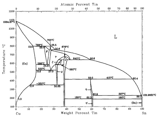
Figure 1.
Phase diagram of the binary CuSn alloy [12]. Reproduced with permission from Bulletin of Alloy Phase Diagrams, Springer Nature, 1990.
As shown in Figure 2, the melting point of CuTi alloy is relatively low when the content of Ti alloy is 20~30%. However, Ti is a very reactive metal and tends to interact with carbon on the surface of a diamond substrate. This results in the formation of a brittle TiC compound [13]. However, when too much TiC is formed on the binding interface, the strength of the brazed joint will be adversely affected, thus reducing the performance of the formed diamond tool.
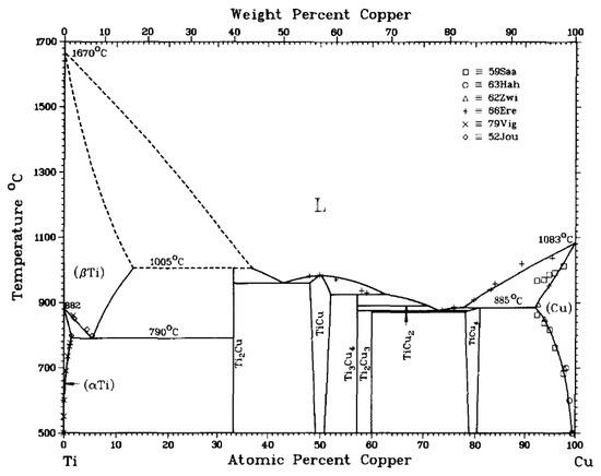
Figure 2.
Phase diagram of the binary CuTi alloy [14]. Reproduced with permission from Bulletin of Alloy Phase Diagrams, Springer Nature, 1983.
Khalid et al. [15] analyzed the diamond-CuSnTi PBFM interface. As shown in Figure 3, the interface features two layers of TiC structures. One layer is close to the TiC grain layer of diamond. The layer of TiC was discontinuous and cubic. The other layer is the base. Acicular and cylindrical TiC grains grow from the cube structure. The acicular and cylindrical TiC structure has less carbon content than the discontinuous and cubic TiC structure. The grain growth features a distinct orientation. The total thickness of the two TiC layers is about 200 nm, as shown in Figure 3.
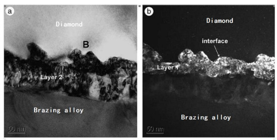
Figure 3.
TEM (transmission electron microscope) photographs of two TiC layers after interface reaction: (a) bright field image; (b) dark field (DF) image g-vector = (111) TiC [15]. Reproduced with permission from Scripta Materialia, Elsevier, 2004.
Deng et al. [16] used Cu10Sn5Ti brazing filler metal (Figure 4) to conduct a vacuum brazing of Ti-coated diamond on the steel substrate. The scanning electron microscope (SEM) photo and X-ray diffraction (XRD) patterns are shown in Figure 5. The substrate, diamond, and brazing filler metal have formed a strong metallurgical bond. The Ti coating layer protects the diamond from thermal damage and graphitization, hence ensuring the integrity of the diamond crystal. The thermal shock strength at 900 °C is reduced by only 1.1%. In the process of grinding, shedding of the whole piece of diamond seldom occurs, while different-sized broken pieces dominate.
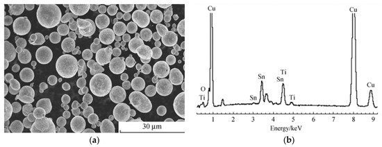
Figure 4.
(a) SEM photograph; (b) EDS spectrum of Cu10Sn5Ti brazing filler metal powder [16]. Reproduced with permission from Journal of the Chinese Ceramic Society, 2011.
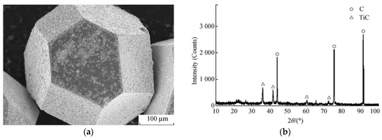
Figure 5.
(a) SEM photograph; (b) XRD pattern of Ti-coated diamond particle surface [16]. Reproduced with permission from Journal of the Chinese Ceramic Society, 2011.
The mechanism of brazing diamond by CuSnTi alloy has been studied extensively. Guo et al. [17] have considered the interface microstructure of a vacuum brazing diamond on 45 steel with CuSnTi alloy. They found that Ti participated in the reaction at the interface of diamond and liquid brazing filler metal, leading to C + Ti → TiC. The reactive wetting has been established [18]. Liu et al. [19] studied the interface features of diamond and cubic boron nitride brazed with CuSnTi alloy. Figure 6 shows the X-ray diffraction (XRD) data of the resulting surface morphology after brazing. As can be seen, the compounds TiC, CuTi, and Cu2Ti are formed on the bonding interface, indicating a metallurgical reaction between CuSnTi alloy and diamond. It can be hypothesized that an epitaxial growth takes place on the diamond crystal, thus forming a TiC interface domain between diamond and the liquid alloy. Hence, the CuSnTi infiltration over diamond has been transformed into an infiltration over the TiC interface. With increasing temperature, brazing filler metal melts and spreads over the steel substrate. The steel substrate, in turn, dissolves into the liquid brazing filler metal. Among the elements Cu, Ti, and Fe, the Cu-Fe series binary component had a low mutual solubility and does not form any intermetallic phases. The melting point of Sn (232 °C) is significantly lower than that of Fe (1535 °C). Iron and tin are dissolved and spread at the brazing temperature, facilitating a metallurgical bonding. The Fe-Ti binary phase diagram indicates that an intermetallic compound may form between Fe and Ti, thus achieving the strong bonding between the brazing filler metal and the steel substrate [20].
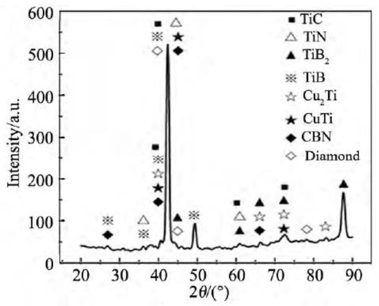
Figure 6.
XRD profile at a brazing interface [19]. Reproduced with permission from Liu et al., Journal of Synthetic Crystals, 2015.
It could be concluded that TiC plays a pivotal role in the CuSnTi brazing of diamond. How to obtain small TiC grains (to facilitate the grain refining effect) will be the main direction of future research.
3.2. High Temperature (≥900 °C) PBFMs
When the brazing temperature is low, or the dwell time at the peak temperature, is short, the chemical reaction at the interface may not be sufficient. The effective contact area of the reaction layer with the parent metal would be reduced, hence resulting in a lower binding force. It is also noticed that microscopic defects, e.g., voids, may appear. The appearance of voids and the contact area reduction clearly weaken the interface bond. Under harsh conditions, low-temperature fillers can no longer meet service requirements. Therefore, a high-temperature powder brazing filler metal should be considered for a high-load diamond workpiece. The most commonly-used brazing filler metal would be Ni-Cr based PBFM such as 84Ni8Cr3B5Si and 76Ni14Cr10P.
Wang et al. [21] have studied the microstructure and corresponding properties of the brazed diamond grit over a steel substrate using Ni-Cr-P filler metal, Figure 7 and Figure 8. Within the interface domain of diamond and the brazing alloy zones, A and B in Figure 7a,b, (marked with the white arrows), were selected for a study. Zones A and B are identified as (i) the reaction layer of the brazing alloy, and (ii) the reaction layer of diamond, respectively. The eight spots (marked as 1 through 4, and 5 through 8 in Figure 8a,b, respectively, were analyzed by EDX (energy dispersive X-ray spectroscopy), Table 1 and Table 2. From this study, we learn that the cross-diffusions of Ni, Cr and Fe between the brazing alloy and steel substrate occur, which will be discussed in more detail below. Moreover, the experimental results show that the interface reaction layer and the diamond gravel were within the well wetted area, so that the reaction layer has produced a high-strength bonding.
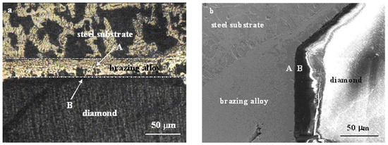
Figure 7.
(a) Optical micrograph; (b) SEM photograph of the interface between brazing alloy, diamond and steel substrate [21]. Reproduced with permission from Journal of Alloys and Compounds, Elsevier, 2009.
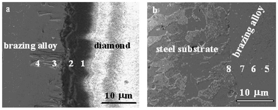
Figure 8.
SEM photograph of (a) interface between diamond and brazing alloy and (b) interface between brazing alloy and steel substrate [21]. Reproduced with permission from Journal of Alloys and Compounds, Elsevier, 2009.

Table 1.
Chemical compositions (%) by EDX from different locations in Figure 7a.
Table 2.
Chemical compositions (%) by EDX from different locations in Figure 7b.
Trenker and Seidemann [22] have reported bonding of the substrate and diamond using both not disclosed nickel-based brazing filler metal and not disclosed nickel-based active brazing filler metal. This kind of bonded high-temperature brazing diamond tool has a much better performance than an electroplating-bonded diamond tool. In terms of initial grinding performance, a high-temperature brazed diamond tool is over three times better than an electroplated tool (expressed in terms of the stock removal magnitude, as shown in Figure 9) [22]. Moreover, the service life of an assembled tool is three times longer than that of an electroplated tool. The grinding performance of a brazed diamond tool is better because the brazed tool has a larger free surface for chipping and grinding between the diamond grits and the workpiece. Moreover, the brazed tool has more intergranular space, which makes chip removal easier [23].
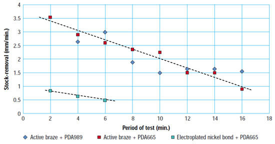
Figure 9.
Comparison of stock-removal with electroplated and brazed pencil grinders [22].
Xiao et al. [24] used Cr powder and AgCu alloy as intermediate materials to form a brazing filler metal to braze a steel substrate and diamond. They found that CrC forms between the brazing filler metal and diamond. FexCryC forms between Cr and steel substrate [25,26]. The addition of Cr enhances the bonding strength at the interfaces of both (i) diamond and brazing filler metal, as well as (ii) steel substrate and brazing filler metal. The EDS spectrum of the intermediate product is shown in Figure 10. The Cr energy spectrum peak indicates that Cr diffuses into the diamond. XRD analysis shows that Cr3C2 forms as an intermediate product. A Cr-rich layer, mainly composed of Cr-containing carbide, is formed as well. The Fe energy spectrum peak means that the alloy layer reacts with the steel matrix to form FexCryC. As a result, this brazing process ensures a good bonding strength.
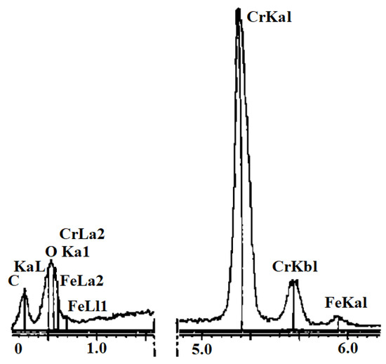
Figure 10.
EDS spectrum of intermediate products [25]. Reproduced with permission from Xiao et al., Transactions of the China Welding Institution, 2001.
The main phenomenon involving an interfacial bonding mechanism for steel and diamond, using a Ni-Cr alloy, is the cross-diffusion of Ni, Cr, and Fe between the brazing alloy and the steel substrate [21]. Figure 11 represents a simplified diagram of the interface bonding mechanism of the Ni-Cr alloy used for brazing diamond and a steel substrate. A brazing alloy reaction layer forms mainly because the graphitized C infiltrates the liquid alloy on the surface of the diamond, and then forms two interface compounds, Cr3C2 and Cr7C3. Due to the high concentration of C in the area adjacent to the diamond, Cr3C2 nucleates in the region near diamond and grows in the direction of the liquid alloy, while Cr7C3 forms in the carbon-depleted region. The proximity of the brazing filler metal layer to the diamond bonding interface leads to the presence of a larger amount of Cr in that domain. Cr would concentrate near the surface of the diamond, and reacts with C, subsequently forming Cr3C2 and Cr7C3. In turn, this becomes the key factor in achieving solid bonding [27,28,29].
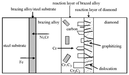
Figure 11.
Schematic diagram of the bonding mechanism of a Ni-Cr alloy filler brazing diamond and a steel substrate [21]. Reproduced with permission from Journal of Alloys and Compounds, Elsevier, 2009.
In addition to the formation of the brazing alloy reaction layer, a diamond reaction layer is also formed at the interface. At the brazing temperature, the diamond surface features many crystal defects, such as dislocations. These defects are energetically high, preferentially graphitized, and continue to dissolve into the filler metal. Cr reacts with the graphitized C and the resulting Cr3C2 permeates into the crystal defects, forming a diamond reaction layer. The main components of the diamond reaction layer include graphitized C and an infiltrated Cr3C2 [30].
The degree of diamond graphitization is a topic of a particular interest and needs to be studied more closely. Too much graphitization causes thermal damage to diamond, but too little graphitization affects the quality of the joint [31,32]. Another major cause of the diamond thermal damage is brazing temperature that is too high. Therefore, selecting a proper set of alloying elements, decreasing the melting point of the brazing temperature segment, and inhibiting the transformation of diamond into graphite (to a certain degree) can reduce the thermal damage of diamond. This may lead to a joint performance improvement, which is yet another important research direction.
4. The Research Status of PBFMs for Impregnated Diamond Tools
Previous sections describe the research status of the PBFM for monolayer brazed diamond tools. However, at present these tools still have a low market share (the monolayer brazed diamond blade tends to wear and tear). Impregnated diamond tools occupy a considerably larger proportion of the market (the market share may reach more than 85%). Impregnated diamond tools are extensively used in mineral mining, oil drilling, coal mining, geological drilling, stone processing, and the architectural ceramics industry [33]. The performance of impregnated diamond tools, and in particular the service life of a diamond cutting bit, depend largely on the performance of the PBFM used for the tool assembly [34]. Powder filler metals for impregnated brazing diamond tools have very good prospects in novel applications.
As already emphasized, there are two ways of manufacturing impregnated diamond tools using PBFMs. One is directly mixing PBFM (called prealloy powders in the diamond tool industry [35,36,37,38]) and the diamond bit, and then sintering into a tool bit. By brazing the tool bit to the metal substrate, one obtains an impregnated diamond tool. The other way is by applying a PBFM to the interface between a cutting bit and a substrate before brazing. The braze is called as the paste brazing filler metal [5].
Prealloy powder is added to the powder of a tool bit. It, as a “binder”, facilitates the diffusion bonding and brazing of diamond by powder sintering [39]. Such filler metal mainly uses active prealloy PBFMs, including strong carbide-forming elements such as Ti, Cr, and V [40]. These elements are first smelted into prealloy, involving metals like Cu, Sn, and Ni, and then made into a reactive PBFM through atomization [41]. The melting temperature of this reactive prealloy powder (i.e., a powder active brazing filler metal) matches the sintering temperature of the diamond bit. The hot pressing sintering process is a diffusion bonding and brazing process, while the cold pressing sintering process is a brazing process [42]. Both hot and cold pressing processes can achieve the reaction of high melting point elements with diamond at a medium temperature, and form a braze-welding joint. The bonding strength of the braze-welding joint with diamond is higher than the mechanical holding strength (the maximum force at which the diamond drill bits do not fall off). In the process of grinding, diamond has a large height of protrusion and a high cutting efficiency. Prealloy powder for impregnated diamond tools improves the utilization rate of diamond, and prolongs the service life of diamond tools. On the other hand, prealloy PBFM is beneficial to the homogenization and manufacturing automation of the tool bit components. A diamond bit has a superior quality stability compared with the tool bit produced with a single metal PBFM [43].
The bonding mechanism of an impregnated diamond tool at the brazing interface can be interpreted as follows: At the bond interface, a chemical reaction forms columnar and acicular structures of carbide, achieving a high-strength metallurgical bonding between the brazing filler metal layer and diamond [44]. For example, in the case of the Ni-Cr brazing filler metal, the product of the chemical reaction appears to be CrxCy (mainly Cr7C3, and a small amount of Cr3C2) [45,46].
Reactive prealloy brazing filler metal powder has resolved several technical drawbacks, e.g., the loss of low melting point elements in the brazing filler metal, a difficulty in achieving the high melting point elements playing an assigned role, a volatility of high vapor pressure elements, a structural segregation of components, and ultimately an instability in the bonding strength. However, there are still many problems for the brazing of impregnated diamond tools to be resolved, e.g., a brazing diamond surface can feature cracks [47]. The cracks and/or crushes stem from the high brazing temperature of the Ni-Cr brazing filler metal used in brazing impregnated diamond tools. Moreover, considerable differences between the thermal expansion coefficients of diamond and brazing filler metal are evident [48]. As a result, high residual stress appears in the cooling segment of the brazing cycle, hence causing cracks of the brazing filler metal and diamond layer domain. Current research of impregnated diamond tools brazing mainly focuses on the numerical simulation of thermal stresses [49,50,51]. In these studies, the intermediate carbide layer is not prominently considered. Therefore, consideration of the thermal stress involving the carbide layer will become a promising objective of impregnated diamond tool brazing investigation.
Paste brazing filler metal is used for brazing diamond tool bits following brazing automation requirements. Compared with the flaky brazing filler metal, the paste PBFM has the advantage of convenient implementation of automation. Moreover, the powder or paste brazing filler metals can be flexibly added to various forms of brazing gap designs. Furthermore, the filler metal dosage can be flexibly controlled.
Finally, with the expansion and deepening of studies of PBFM, yet another advantage in the brazing of diamond tools is found to be the novel application of a high Sn-alloyed Ag-Cu-Zn-Sn brazing filler metal, in the form of a PBFM [52,53,54]. As it is difficult to roll the Cd-free brazing filler metals with high tin content, such brazing filler metals are difficult to make into sheet strips, limiting their applications [55]. Still, the increased use and promotion of PBFM has widened the composition range of silver-copper-zinc-tin brazing filler metals, broadening their applications as well.
5. Conclusions
PBFMs are characterized by accurate dosage and high brazing efficiency. Their application characterizes an easy implementation in automated production. In recent years, researchers have done a wealth of research on monolayer brazing filler metal for diamond tools applications. The studies of CuSnTi PBFMs indicate that the mechanism of brazing diamond involves the reaction of Ti with C to form TiC. However, the resulting TiC formations are brittle. Refinement of the TiC grains is needed to avoid brittle joints. A Ni-Cr PBFM is a high-temperature brazing filler metal which can be used on workpieces that are highly loaded. The main phenomenon involving the interfacial bonding mechanism is the cross-diffusion of Ni, Cr, and Fe between the brazing alloy and steel substrate. However, at high temperatures, diamond will be graphitized. Reducing the melting point of a brazing filler metal by adding adequate alloying elements would be needed, so that the transformation of diamond to graphite is inhibited. It should be pointed out that the brazing filler metal for impregnated diamond tools mainly comprises active prealloy PBFMs. The research is primarily limited to thermal stress predictions. However, thermal stress studies must also involve the formation of an intermediate carbide layer.
Author Contributions
Fei Long, Peng He and Dusan P. Sekulic wrote the paper with equal contribution.
Acknowledgments
The authors greatly appreciate the National Key Research and Development Program of China (Grant No. 2016YFE0201300), the National Natural Science Foundation of China (Grant No. 51474081 and 51475103), and “the Funds for Distinguished Young Scientists of Heilongjiang Province (Grant No. JC2015011)”. One of the authors (DPS) acknowledges a support through the “1000 Talent Plan for High-Level Foreign Experts” Program and the Foreign Expert Chair Professorship at the Harbin Institute of Technology.
Conflicts of Interest
The authors declare no conflict of interest.
References
- Hofmann, E.; Rüsch, M. Industry 4.0 and the current status as well as future prospects on logistics. Comput. Ind. 2017, 89, 23–34. [Google Scholar] [CrossRef]
- Theorin, A.; Bengtsson, K.; Provost, J.; Lieder, M.; Johnsson, C.; Lundholm, T.; Lennartson, B. An event-driven manufacturing information system architecture for Industry 4.0. Int. J. Prod. Res. 2016, 48, 1–15. [Google Scholar] [CrossRef]
- Chen, Z.X.; Chen, P.; Cai, Z.H.; Zeng, Y.; Liu, H.J. Introduction to production and application of soldering and brazing filler metal powders and pastes in China. Rare Met. 2009, 28, 471–473. [Google Scholar]
- Wan, C.; Xiong, H.; Zhou, Z. Joining of Si3N4/Si3N4 with CuNiTiB paste brazing filler metals and interfacial reactions of the joints. J. Mater. Sci. 1999, 34, 3013–3019. [Google Scholar] [CrossRef]
- Nadkarni, A.V.; Cowan, G.L.; Garrard, A.V.; Khattar, R. Powder metal pastes for brazing and soldering applications. Int. J. Powder Metall. 2001, 37, 49–60. [Google Scholar]
- Ivanov, E.Y.; Shapiro, A.E.; Horne, M.G. Exploring solid-state synthesis of powder filler metals for vacuum brazing of titanium alloys. Weld. J. 2006, 85, 196–199. [Google Scholar]
- He, P.; Liu, D.; Shang, E.; Wang, M. Effect of mechanical milling on Ni-TiH powder alloy filler metal for brazing TiAl intermetallic alloy: The microstructure and joint’s properties. Mater. Charact. 2009, 60, 30–35. [Google Scholar] [CrossRef]
- Liu, G.W.; Qiao, G.J.; Wang, H.J.; Yang, J.F.; Lu, T.J. Pressureless brazing of zirconia to stainless steel with Ag-Cu filler metal and TiH powder. J. Eur. Ceram. Soc. 2008, 28, 2701–2708. [Google Scholar] [CrossRef]
- Zhang, L.; Tu, K.N. Structure and properties of lead-free solders bearing micro and nano particles. Mater. Sci. Eng. R 2014, 82, 1–32. [Google Scholar] [CrossRef]
- Chattopadhyay, A.K.; Roy, P.; Sarangi, S.K. Study of wettability test of pure aluminum against uncoated and coated carbide inserts. Surf. Coat. Technol. 2009, 204, 410–417. [Google Scholar] [CrossRef]
- Sekulic, D.P. Advances in brazing: Science, technology and applications. Woodhead 2013, 80, 423–471. [Google Scholar]
- Saunders, N.; Miodownik, A.P. The Cu-Sn (Copper-Tin) system. Bull. Alloy Phase Diagr. 1990, 11, 278–287. [Google Scholar] [CrossRef]
- Klotz, U.E.; Khalid, F.A.; Elsener, H.R. Nanocrystalline phases and epitaxial interface reactions during brazing of diamond grits with silver based Incusil-ABA alloy. Diam. Relat. Mater. 2006, 15, 1520–1524. [Google Scholar] [CrossRef]
- Murray, J.L. The Cu-Ti (Copper-Titanium) system. Bull. Alloy Phase Diagr. 1983, 4, 81–95. [Google Scholar] [CrossRef]
- Khalid, F.A.; Klotz, U.E.; Elsener, H.R.; Zigerlig, B.; Gasser, P. On the interfacial nanostructure of brazed diamond grits. Scr. Mater. 2004, 50, 1139–1143. [Google Scholar] [CrossRef]
- Deng, Z.; Wu, Q.; Zhang, R.; Pan, Z. Vacuum brazing of Ti-coated diamonds with Cu-based alloy powder. J. Chin. Ceram. Soc. 2011, 39, 343–348. [Google Scholar]
- Guo, Z.C.; Chen, Y.; Hong-Hua, S.U.; Yu-Can, F.U. Microstructure for interface between diamond and 45 steel vacuum-brazed by Cu-Sn-Ti alloy. Mater. Mech. Eng. 2012, 36, 20–22. [Google Scholar]
- Li, Y.; He, P.; Feng, J. Interface structure and mechanical properties of the TiAl/42CrMo steel joint vacuum brazed with Ag-Cu/Ti/Ag-Cu filler metal. Scr. Mater. 2006, 55, 171–174. [Google Scholar] [CrossRef]
- Liu, S.X.; Xiao, B.; Zhang, Z.Y.; Duan, D.Z.; Xu, F.L.; Wang, B. Microanalysis of interface characteristics of brazed diamond and cubic boron nitride abrasive with Cu-Sn-Ti filler alloy. J. Synth. Cryst. 2015, 44, 1161–1165. [Google Scholar]
- Terakubo, M.; Oh, J.; Kirihara, S.; Miyamoto, Y.; Matsuura, K.; Kudoh, M. Freeform fabrication of Ti-Ni and Ti-Fe intermetallic alloys by 3D micro welding. Intermetallics 2007, 15, 133–138. [Google Scholar] [CrossRef]
- Wang, C.Y.; Zhou, Y.M.; Zhang, F.L.; Xu, Z.C. Interfacial microstructure and performance of brazed diamond grits with Ni-Cr-P alloy. J. Alloys Compd. 2009, 476, 884–888. [Google Scholar] [CrossRef]
- Trenker, A.; Seidemann, H. High-vacuum brazing of diamond tools. Ind. Diam. Rev. 2002, 62, 49–51. [Google Scholar]
- Zhang, F.L.; Zhou, Y.M.; Guo, C.W.; Mao, J.B.; Huang, H.P. Performance of brazed diamond tool for machining dental ceramic. Adv. Mater. Res. 2014, 1027, 84–87. [Google Scholar] [CrossRef]
- Xiao, B.; Xu, H.J.; Wu, Z.B.; Xi, P. Furnace brazing of diamond grinding wheel with Ni-Cr alloy under vacuum atmosphere. Mech. Sci. Technol. 2001, 22, 23–26. [Google Scholar]
- Wu, Z.B.; Xu, H.J.; Xiao, B. Experimental investigation on induction brazing of diamond grinding wheel. Trans. China Weld. Inst. 2001, 22, 24–26. [Google Scholar]
- Xiao, B.; Wu, Z.B.; Xu, H.J. Expermental investigation on induction brazing of diamond grinding wheel with Ni-Cr alloy under vacuum atmosphere. Tool Eng. 2000, 34, 3–5. [Google Scholar]
- Yang, Z.B.; Xu, J.H.; Liu, A.J. Delaminating behavior and formation mechanism of the interfacial microstructure in the laser brazing diamond with Ni-Cr alloys. Chin. J. Lasers 2009, 36, 3079–3083. [Google Scholar] [CrossRef]
- Sun, B.; Meng, P.; Lu, J.B.; Zhao, B.; Liu, J.J. Influence of brazing time on microstructure of high temperature brazing diamond with Ni-Cr alloy. Adv. Mater. Res. 2012, 452–453, 628–632. [Google Scholar]
- Lu, J.B.; Meng, P.; Zhao, B.; Liu, J.J. Nucleation and growth of Cr7C3 of brazing diamond with Ni-Cr alloy in protective atmosphere furnace. Adv. Mater. Res. 2012, 463–464, 505–509. [Google Scholar]
- Zhu, Y.; Wang, L.; Yao, W.; Cao, L. The interface diffusion and reaction between Cr layer and diamond particle during metallization. Appl. Surf. Sci. 2001, 171, 143–150. [Google Scholar] [CrossRef]
- Qian, J.; Pantea, C.; Huang, J.; Zerda, T.W.; Zhao, Y. Graphitization of diamond powders of different sizes at high pressure-high temperature. Carbon 2004, 42, 2691–2697. [Google Scholar] [CrossRef]
- Saguy, C.; Cytermann, C.; Brener, R.; Richter, V.; Shaanan, M.; Kalish, R. Damage threshold for ion-beam induced graphitization of diamond. Appl. Phys. Lett. 1995, 67, 1194–1196. [Google Scholar] [CrossRef]
- Konstanty, J.; Kim, T.W.; Kim, S.B. Resistance to abrasive wear of materials used as metallic matrices in diamond impregnated tools. Mater. Sci. Forum 2007, 534–536, 1125–1128. [Google Scholar] [CrossRef]
- Luo, X.; Ma, H.; Huang, M.; Tang, M. Research and application of cobalt-substitute prealloy powder for diamond tools. Diam. Abras. Eng. 2006, 26, 18–24. [Google Scholar]
- Xiang, B.; Xie, Z.; He, Y.; Huang, Y. Preparation of prealloyed powder for matrix of diamond tools. Diam. Abras. Eng. 2006, 26, 34–38. [Google Scholar]
- Cai, F.; Tang, X.; Qin, Y.; Li, L.; Zhu, G. The research trends of the prealloyed powder used in diamond tools. Diam. Abras. Eng. 2004, 24, 77–80. [Google Scholar]
- Xu, H.; Ma, H.; Luo, X.; Zhao, T. Atomized prealloyed powders and it’s application in diamond tools. Diam. Abras. Eng. 2004, 24, 45–48. [Google Scholar]
- Chu, Z.; Guo, X.; Zhang, L.; Liu, D. Effect of super high pressure water atomization parameters on diameter and micrograph of diamond matrix prealloy powders. Mater. Sci. Eng. Powder Metall. 2015, 20, 808–814. [Google Scholar]
- Elsener, H.R.; Klotz, U.E.; Khalid, F.A.; Piazza, D.; Kiser, M. The role of binder content on microstructure and properties of a Cu-base active brazing filler metal for diamond and cBN. Adv. Eng. Mater. 2005, 7, 375–380. [Google Scholar] [CrossRef]
- Weber, L.; Tavangar, R. On the influence of active element content on the thermal conductivity and thermal expansion of Cu-X (X = Cr, B) diamond composites. Scr. Mater. 2007, 57, 988–991. [Google Scholar] [CrossRef]
- Cao, C.; Liu, Y.; Xu, L.; Shen, N.; Liu, Z. Study on hot pressing sintering behaviors and properties of Cu-Sn pre-alloy powder high Sn content. Diam. Abras. Eng. 2016, 36, 67–72. [Google Scholar]
- Zhang, G.F.; Zhang, J.X.; Wang, S.Y.; Qiu, F.X. Similarities and differences in main characteristics between transient liquid phase bonding and brazing process. Chin. Weld. Inst. 2002, 23, 92–96. [Google Scholar]
- Cao, C.; Liu, Y.; Xu, L.; Shen, N.; Liu, W. Influence of granulating process on the properties of Cu-Sn prealloy powder diamond tools. Diam. Abras. Eng. 2015, 35, 67–71. [Google Scholar]
- Duan, D.; Xiao, B.; Wang, W.; Zhang, Z.; Wang, B. Interface characteristics and performance of pre-brazed diamond grains with Ni-Cr composite alloy. J. Alloys Compd. 2015, 644, 626–631. [Google Scholar] [CrossRef]
- Chen, Y.; Xu, H.; Fu, Y.; Su, H. Surface graphitization on brazed diamond with Ni-Cr alloy in vacuum brazing. Trans. Chin. Weld. Inst. 2009, 30, 21–24. [Google Scholar]
- Lu, J.; Xu, J.; Xu, H.; Fu, Y.; Jiang, C. Thermodynamic studies on interfacial reactions between diamond and Ni-Cr filler metal in vacuum brazing. Trans. Chin. Weld. Inst. 2004, 25, 21–24. [Google Scholar]
- Das, N.K.; Tirtom, I.; Shoji, T. A multiscale modelling study of Ni-Cr crack tip initial stage oxidation at different stress intensities. Mater. Chem. Phys. 2010, 122, 336–342. [Google Scholar] [CrossRef]
- Stoupin, S.; Shvyd’Ko, Y.V. Thermal expansion of diamond at low temperatures. Phys. Rev. Lett. 2010, 104, 085901. [Google Scholar] [CrossRef] [PubMed]
- Zheng, L.; Huan, H.; Zeng, Y.; Song, S.; Cheng, S.; Zhang, C. A study on the failure mechanism and wear loss of impregnated diamond bits during machining process of armor ceramics. J. Mech. Sci. Technol. 2018, 32, 261–268. [Google Scholar] [CrossRef]
- Xu, J.; Sheikh, A.H.; Xu, C. 3-D Finite element modelling of diamond pull-out failure in impregnated diamond bits. Diam. Relat. Mater. 2017, 71, 1–12. [Google Scholar] [CrossRef]
- Li, Q.L.; Xu, J.H.; Su, H.H.; Fu, Y.C. Simulation of temperature field induced in localized ultra-high frequency induction brazing of diamond tools. Adv. Mater. Res. 2012, 565, 633–638. [Google Scholar] [CrossRef]
- Gao, G.; Hu, J.H.; Cheng, C.; Wu, X.; Zhang, D. Forming equation about multivariate mixed metal powder by electromagnetic compaction. Chin. J. Nonferr. Met. 2015, 25, 1937–1942. [Google Scholar]
- Mayappan, R.; Abidin, N.N.Z.; Ghani, N.A.A.; Yahya, I.; Shuhaime, N. Intermetallic study on the modified Sn-3.5Ag-1.0Cu-1.0Zn lead free solder. Mater. Sci. Forum 2016, 857, 3–7. [Google Scholar] [CrossRef]
- Gain, A.K.; Chan, Y.C.; Sharif, A.; Yung, W.K.C. Effect of small Sn-3.5Ag-0.5Cu additions on the structure and properties of Sn-9Zn solder in ball grid array packages. Microelectron. Eng. 2009, 86, 2347–2353. [Google Scholar] [CrossRef]
- Zhang, T.; Xue, S.; Ma, C. Research status of Ag-Cu-Zn series brazing filler metals. Weld. Join. 2014, 58, 10–15. [Google Scholar]
© 2018 by the authors. Licensee MDPI, Basel, Switzerland. This article is an open access article distributed under the terms and conditions of the Creative Commons Attribution (CC BY) license (http://creativecommons.org/licenses/by/4.0/).