Abstract
Rolling contact fatigue and wear of wheel–rail systems are critical factors affecting the safety of high-speed railways and have long been key research topics in materials science. This paper reviews the theoretical foundations of wheel–rail rolling contact fatigue, introduces representative experimental methods for studying rolling contact fatigue, and discusses the stress–strain problems in wheel–rail contact. Additionally, it provides a detailed overview of the emerging computational simulation approach for rolling contact fatigue wear, summarizes commonly used simulation software and their respective characteristics, and analyzes material factors influencing rolling contact fatigue simulations in wheel–rail steels. Finally, based on the classification of rolling contact fatigue algorithms, various measures are proposed to enhance rapid and accurate detection and evaluation.
1. Introduction
Since the second half of the 20th century, high-speed railways have reshaped the global rail transportation landscape as a revolutionary force. Figure 1 shows the urban rail transit operating mileage in major continents as of 2022. The rapid increase in railway mileage is mainly due to the emphasis placed by various countries on the development of the railway sector. Europe has planned to establish strategic corridors spanning 26 countries based on the “Trans-European High-Speed Rail Network”, leveraging infrastructure to drive regional economic integration. Japan pioneered high-speed rail with its Shinkansen system, maintaining international leadership in precision track control and earthquake early-warning technologies. Meanwhile, countries such as the United States, South Korea, and India are accelerating the development of their national high-speed rail backbone networks. China has achieved rapid progress in high-speed rail construction. The country’s total railway operational mileage reached 159,000 kilometers, including 45,000 kilometers of high-speed lines [1]. Projects like the Beijing–Shanghai High-Speed Railway and the Fuxing bullet trains have become global hallmarks of Chinese manufacturing. Figure 2 shows China’s current and planned high-speed rail network between 2003 and 2030, In the future, China will continue to develop its railway industry according to this plan.
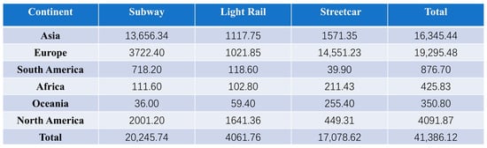
Figure 1.
Summary of urban rail transit operational mileage by continent worldwide (2022).
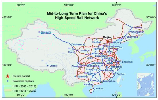
Figure 2.
China’s current and planned high-speed rail network between 2003 and 2030 [2].
With the continuous advancement of high-speed rail technology, the materials science and processing techniques of rail steels have undergone extensive development. Railway track steels primarily consist of austenitic high-manganese steels, bainitic steels, and pearlitic steels, with experimental applications of martensitic steels also being documented [1]. In 1894, the United States pioneered the use of high-manganese steel as rail material. Owing to its exceptional strain-hardening capability, wear resistance, cost-effectiveness, and longevity, this steel became the preferred material for railroad frogs and has been widely adopted in such applications [3]. Pearlitic rail steel constitutes the most extensively used grade in railway tracks. As axle loads increase and demands for strength, hardness, and wear resistance grow, pearlitic rail steels have evolved from hypoeutectoid steels to eutectoid steels, and further, to hypereutectoid pearlitic steels [1]. Research on bainitic rail steels primarily aims to enhance the load-bearing capacity and service life of frogs. Through alloying design and optimized heat treatment processes, various bainitic rail steels have been developed, including Molybdenum-alloyed bainitic steels, Manganese-alloyed bainitic steels, Carbide-free bainitic steels.
Amid ongoing high-speed rail development, the railway industry continues to deal with serious wheel–rail rolling contact fatigue (RCF) issues. RCF in rail steels remains a constant challenge, prompting continued research in materials science. To tackle this critical problem, both theoretical and experimental studies on RCF of rail steels have been conducted. The rolling contact fatigue test of rail steel involves evaluating the fatigue performance of rail steel by simulating its rolling contact during train operation. This type of experimental research helps us understand the fatigue damage that may occur during the use of rail steel, enabling us to implement appropriate preventive measures.
Despite trying various methods and measures, including developing new types of wheel–rail materials, optimizing the matching of wheel–rail profiles, and improving the structural performance of tracks and vehicles, these approaches have not fundamentally solved the issue of fatigue damage.
In 1998, a major traffic accident occurred when a German ICE train derailed, resulting in the tragic loss of 101 lives. The cause of this accident was identified as a fatigue fracture of the train wheel material [4]. On 6 February 2020, a high-speed rail derailment accident occurred in Livlaga, Lombardy, Italy, resulting in 2 deaths and 31 injuries [5]. The Xi’an-Chengdu High-Speed Railway, which opened in 2017, frequently encounters steep ramp conditions along its route, leading to severe wheel slippage problems and subsequent rail abrasion. It is estimated that approximately billions of yuan are annually invested in the maintenance and replacement of rails [5].
Researchers use experimental simulations of the actual operating conditions to carry out research, while also exploring new ways to solve research problems. With the continuous progressions in computer technology, simulations have been applied to a large number of topics to explore if a complete mechanical model of the wheel track and effective numerical methods can be established through experimental simulation and simulation to determine the form of the force between the wheel track and the relationship between the wheel track and the relative motion of the wheel track; they can also take into account the real geometric surface of the wheel track, the real boundary conditions, the elasticity–plasticity deformation of the material and the friction contact boundary conditions (such as surface roughness, discontinuous contact surface and temperature, etc.). Then, it is possible to solve the problems of the wheel track, such as surface roughness, discontinuous contact surface and temperature, etc., and then, a solution for the rolling contact fatigue problem is, in theory, provided. Rolling contact fatigue simulation combined with experimental simulation research method thus came into being; compared with the experimental simulation analysis, simulation can be applied to the track unevenness, wheel diameter difference and other wheel track data to make the simulation closer to the actual operation of the train, and accurately restore the vehicle in the track of the different operating conditions. Experimental simulation as a control can fully verify the correctness of the simulation results; the two together reveal the influence of wheel rail parameters and material parameters on the rolling contact fatigue life of wheel rails.
This paper takes the wheel–rail rolling contact fatigue theory as the basis, summarizes the experimental method and research direction of rolling contact fatigue experimental simulation, and introduces the commonly used software, research method, simulation steps, investigation factors and optimization measures of wheel–rail rolling contact fatigue computational simulation. Finally, the research method combining rolling contact fatigue experimental simulation and computational simulation is summarized and outlined, and the direction of future research method development is proposed.
2. Theoretical Basis of Rolling Contact Fatigue of Wheel Track
To comprehend the fundamental issue of rolling contact fatigue, numerous researchers have undertaken studies on its basic theory. Damage to wheel rails caused by rolling contact fatigue (RCF) poses a significant challenge that leads to frequent repairs during actual operations, ultimately shortening the lifespan of wheels and reducing vehicle availability [6]. Consequently, this area has garnered extensive research in academia, and the theoretical foundations of rolling contact fatigue (RCF) in rail steel can be categorized into two primary components: traditional rolling contact mechanics theory and fatigue theory.
2.1. Theory of Rolling Contact
So far, the wheel–rail rolling contact theory has been developed and expanded under the continuous efforts and improvement of several generations of scientists, mainly in the low-frequency dynamics of rolling stock with small creep and slip. The development process of the wheel-rail rolling contact theory is shown in Figure 3. In 1881–1882, Hertz [7] proposed the Hertz contact theory. This theory has played an important role in the development of the railroad industry, but under practical application, it is difficult for the elastic contact surface to meet the ideal frictionless environment. Therefore, the Hertz contact theory can not be analyzed when applied to the actual contact problem [8]. In 1926, Carter [9] published “On the behavior of locomotive moving wheels”, slowly establishing the rolling contact theory of the wheel and rail, in which he considered the use of elastic cylinders as an elastic half-space to simulate the wheel. Through the Hertz theory and the elastic half-space theory, he successfully solved the two-dimensional elastic rolling contact problem. Hertz theory and elastic half-space theory successfully solved the two-dimensional elastomer rolling contact problem. In 1958, Johnson K.L. put forward the creep–slip force saturation effect, that is, the tangential force by the Coulomb friction limit constraints, revealing that the creep–slip force under the large creep–slip rate has the nonlinear characteristics of creep–slip. In 1964, Johnson K.L. [10] studied the rolling contact of an elastic ball in the elastic plane and extended the saturation effect study to the direction of three-dimensional rolling contact. Finally, the Vermeulen–Johnson theory was formed without considering the spin slip condition [10,11]. In 1967, the Dutch scholar J.J. Kalker [12] systematically extended the relationship between creep slip rate and creep slip force to three-dimensional space, and gave the linear law of creep slip rate/force in three-dimensional form, which elevated the creep slip theory to a level that allowed it to be practically applied. In 1972, Cooperrider [13] was the first to systematically analyze and study the nonlinear dynamics of rolling stock systems without considering the spin slip force from the point of view of the nonlinear properties of longitudinal and transverse creep rates, and in 1973, Kalker created a simplified theory of rolling contact based on an analytical study of Cooperrider’s research. After this, Kalker developed a simplified FASTSIM fast algorithm and a formula for the linear theory [8]. In the early 1990s, Kalker utilized the principle of residual-energy variability of classical elastodynamics to establish a non-Hertzian theoretical model for three-dimensional elastomers [6], known as the CONTACT algorithm.
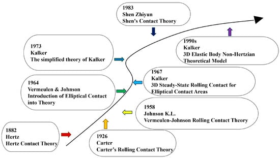
Figure 3.
History of the development of rolling contact theory.
Although the theory of creep–slip rate forces in wheel–rail rolling contact is constantly evolving to accommodate the study of wheel–rail relationship problems, most of the existing theoretical models are still based on the following points: (1) The normal contact is assumed to satisfy the Hertz contact condition; (2) the wheel–rail contact pair is considered as an elastic half-space; (3) the contact surfaces are ideally smooth and continuous, and the influence of the “third medium” (e.g., water, oil, and other pollutants) between the contact surfaces is ignored; (4) the influence of the boundary support and constraint conditions outside the wheel–rail contact patch on the wheel–rail contact behavior is ignored; (5) the inertial force in the high-speed wheel–rail rolling contact is ignored; (6) the influence of temperature is not considered and wheel–rail contact behavior is ignored; However, the above assumptions are not consistent with the actual wheel–rail rolling contact conditions [14]. To solve these problems, the first step is to clarify the relationship between the forces at the wheel–rail contact spot and the related elements, and the finite element method is the most important way to solve these problems.
2.1.1. Hertz Contact Theory
In 1882, the theory for solving the problem of normal elastic contact between two objects involved in wheel tracks was proposed by Hertz [7]. As shown in Figure 4, Hertz proposed that when two equal elastic solid spheres of the same material come into contact with each other, the pressure surface of the contact constitutes a surface with different properties from those of the two surfaces of the contact. Hertz imagined the contact surface to be perfectly smooth, and assuming that there is only normal pressure to the entire surface, this plane can be regarded as an infinitely flat flattened ellipsoid of uniform bulk density. The Hertz contact theory is mainly used to compute the dimensions of the contact region, the maximum contact stresses, and the amount of elastic convergence.
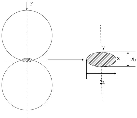
Figure 4.
Sphere contact Hertz theory calculation.
For the contact of two elastic spheres, the contact region is circular, and its radius a is calculated by the following equation [7]:
F is the normal load, is the equivalent radius of curvature, and is the equivalent elastic modulus.
The equivalent radii of curvature ( and are the radii of curvature of the two spheres, respectively) satisfy [7]:
The equivalent elastic modulus (where E1 and E2 are the elastic moduli, and v1, v2 are the Poisson’s ratios) satisfies
For ellipsoidal contact (e.g., contact between a ball and a plane), the contact region is ellipsoidal, with long and short semi-axes a and b, respectively [7]:
where and are the correction coefficients in the direction of the two semi-axes, respectively. For the ellipsoidal contact commonly used in the wheel and rail, the maximum contact stress is at the center of the contact area and the contact stress is distributed in a semi-ellipsoid shape in the contact area. The magnitude of can be expressed as [7]
Hertz’s theory cannot be used to calculate the effect of friction between contact forces. However, the Hertz contact theory is simple and easy to understand and use, and many researchers still use it to analyze the wheel–rail contact normal problem. The Hertz contact theory also lays the foundation for subsequent researchers to study the related wheel–rail contact problems [15].
2.1.2. Carter’s Rolling Contact Theory
In 1926, Carter [9] modeled the wheel–rail contact environment with cylindrical and elastic infinite wheel–rail half-spaces and assumed that the physical constants of both were the same, and through an ingenious analytical method, he delineated the adhesion and sliding zones in the contact patch, and revealed the magnitude and distribution of the acting forces and the law of the relationship between the longitudinal tangential force and creep–slip rate between wheels and rails [16].
Wheel–rail contact theory has nearly a hundred years of history. Wheel–rail rolling contact theory, also known as wheel–rail creep theory, is conceived through the study of the relative motion between the wheel and the track and the analysis of the contact spot to improve the theory.
As shown in Figure 5, when the wheel is in operation, the action of the load will make the wheel–rail contact with each other part of the mutual force, resulting in the occurrence of small elastic deformation, and the formation of a contact area similar to the oval contact area. When the wheel rolls forward, the wheel and rail material in the contact area will undergo elastic deformation; at this time, the two contact surfaces will produce tangential force F (peripheral traction), and this wheel–rail contact state is called adhesion. At the same time, due to the adhesion state, the wheel’s forward speed V is always lower than the wheel’s circumferential speed , and this phenomenon is called creep slip [17].
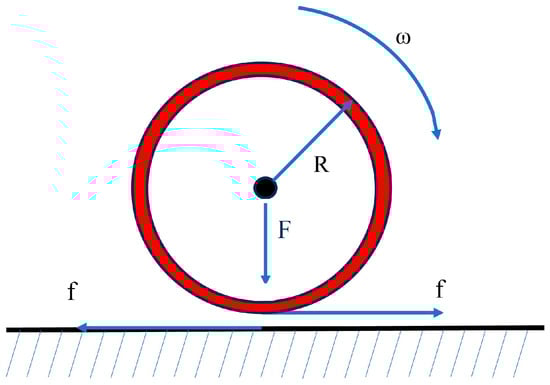
Figure 5.
Schematic diagram of wheel–rail forces.
The degree of creep slip size can be expressed by the creep slip rate, which is defined as
where R is the radius of the wheel, ω is the angular speed of wheel rotation, and v is the true forward speed of the wheel.
For wheel–rail creep, change the tangential force between the wheel–rail contact surface; the creep slip rate will also change, so you can derive the corresponding wheel–rail creep curve, as shown in Figure 6 below. The wheel–rail creep curve can be divided into a linear area, a saturation area, and a falling area, the three parts of the composition. When the traction force is small, the creep slip rate is small. The creep slip force increases linearly with the increase in the creep slip rate; this region is called the linear region. When the traction force continues to increase, the creep slip rate increased dramatically to the maximum value; this region is called the saturation area, at which the creep slip rate reaches the maximum limit of the creep slip rate. When the traction force continues to increase, the creep slip force decreases with the increase in creep slip rate; at this stage, the wheel slips completely. The left side of the limit slip rate belongs to the microscopic creep slip, and the right side belongs to the macroscopic creep slip [17].The depiction of the adhesive-slip band and the distribution of tangential forces during this process are shown in Figure 7.
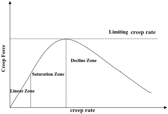
Figure 6.
Wheel–rail creep–slip characteristic curve.
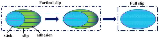
Figure 7.
Delineation of the stick-slip zone and distribution of tangential force in Carter’s theory [18].
For the wheel–rail rolling contact theory, it is still aimed at the low-frequency dynamics of rolling stock, and the creep–slip rate involved is small, which is only applicable to the creep–slip region where the linear and saturation zones are located.
The product of the friction coefficient and positive pressure is the sliding tangential force. Assuming that the entire contact patch is sliding when the wheel–rail contact is made, the actual tangential force at the front of the contact patch a − 2a1 ≤ x1 < a does not reach the limiting value, and the force in the adhesion region is obtained as in Equation [8]:
where a is the half width of the contact zone; a1 is the half width of the stick-slip zone; and is the actual tangential force. When x1 = x − (a − a1), the center of the adhesion zone at x1 = 0; is the normal force; is the coefficient of friction between the wheels and rails; and the three equations represent the tangential force in the three cases of out-of-contact, sliding, and adhesion zones, respectively. is the longitudinal creep–slip rate, i.e., the longitudinal rigidity creep–slip rate [19]:
vt is the circumferential velocity of the rim, and vc is the rolling velocity of the wheelset. The relationship between the half-width of the adhesion zone, a1 and the creep–slip rate can be expressed as [19]
The two equations Fx are the total tangential force per unit of transverse length and the total normal force per unit of transverse length, and R is the radius of the rolling cylinder.
However, this theory does not consider the transverse creep–slip and spin effects between the rolling contact surfaces of the wheel–rail, so it is not applicable to the simulation and analysis of vehicle track dynamics, and cannot solve the problem of wheel–rail interaction.
2.1.3. Vermeulen–Johnson Rolling Contact Theory
Carter’s rolling contact theory is a two-dimensional rolling contact problem, but if it is applied to the simulation of real vehicle dynamics, it is necessary to expand the rolling contact theory to three dimensions.
In 1958, Johnson K.L. [11] initially proposed the Vermeulen–Johnson rolling contact theory, based on Carter’s two-dimensional rolling contact theory, the rolling contact problem three-dimensional elastic ball rolling contact situation.
In 1964, Vermeulen and Johnson [10] generalized the theory to the contact case of elliptical patches on the basis of three-dimensional elastic spherical rolling contact.
Figure 8 shows the distribution of creep–slip and adhesion zones in the contact patch as classified by Vermeulen and Johnson, who still follow Carter’s idea of dividing the elliptical contact patch into two parts: the adhesion zone and the sliding zone.
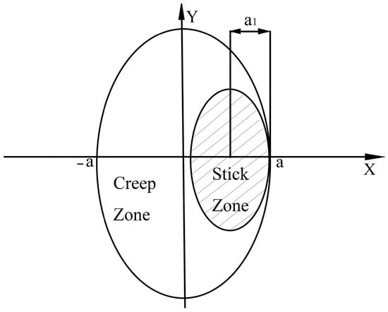
Figure 8.
Vermeulen and Johnson slip zone delineation.
The distribution of tangential force on the contact patch takes the form of Equation [8]:
where a and b represent the semi-major and semi-minor axes of the ellipse, C is the elliptical contact area; S is the sliding area; H is the adhesion area; T1 and T2 are the components of the total tangential force along the x and y directions, respectively, and T = (T12 + T22)1/2, and T is the sum of all the tangential forces in the contact patch; c = a − a1.
The longitudinal and transverse rigid creep slip rates at the contact point are defined as [19]
where , and , are the velocities of the mass pair at the point of contact in the x and y directions, respectively, and ν1 is the rolling velocity of the object in the x direction.
where G is the synthetic modulus of rigidity, C*11 and C*22 are the creep–slip coefficients, ξ*1 is the longitudinal creep–slip rate, and ξ2 is the transverse creep–slip rate.
The model is widely used in vehicle dynamics. The shortcomings of this theoretical model are that it does not take into account the effect of the amount of spin motion between the rolling contact objects on the creep–slip force, it is wrong to classify part of the front edge of the elliptical contact zone as the sliding zone, and it does not give the magnitude of the torque transmitted between the contacting objects, so, when it is used to analyze the wheel–rail force, it may produce certain errors under certain working conditions [20,21].
2.1.4. The Simplified Theory of Kalker
In 1967, Kalker [12], a Dutch scholar, analyzed the three-dimensional steady state rolling contact problem in an elliptical contact region by applying the level method in his doctoral thesis.
In 1973, Kalker [22] developed a fast computational model with the help of the proposed linear theoretical model: the Kalker simplified theory.
In the basic assumptions of Kalker’s linear simplified theory, the two contacting bodies maintain the same material parameters and are specified to be fully adherent in the wheel–rail contact region; the longitudinal/transverse creep–slip rate and the spin creep–slip rate are defined as in the following equation
where ε1, ε2, ε3 are the longitudinal/transverse creep–slip rate and spin-slip rate, respectively; v11, v12 and v12, v22 are the velocities at the mass point in the contact region of wheel and v is the velocity relative to the x and y directions at the mass point in the contact region of the rail; ω1, ω2 are the angular velocities of the wheel–rail rotation at the contact point, respectively [15].
In Kalker’s simplified theory, the force density within the elliptical contact patch formed by wheel–rail contact can be expressed in terms of steps in the form of the following equation [12]:
where dpq, epq, fpq are all constants of the level and are unknown quantities to be determined; p1, p2, and p3 denote the magnitude of the partial force along the direction of x1, x2, and x3 at the wheel–rail contact patch, respectively; and G denotes the shear modulus of elasticity.
The elastic displacement difference is expressed as follows [12]:
In the equation, , , and are constants of the series, while , , and represent the elastic displacement differences.
In this theory, Kalker proposed that when both the longitudinal/lateral creepages and the spin creepage are sufficiently small, the slip zone in the contact area can be neglected, and the entire wheel–rail contact region can be considered to be in a state of full adhesion. Under this condition, the relationship between the creepages and creep forces in the contact area can be expressed as [12]
In the equation, a and b represent the semi-minor axis and semi-major axis of the wheel–rail contact area, respectively; Fx and Fy denote the longitudinal and lateral creep forces, while Mz represents the spin creep moment. C11, C22, C23, C32, and C33 are creep coefficients, which have no analytical expression. These coefficients are related to the computational accuracy of creep forces and spin moments—specifically, higher-order series expansions yield greater precision.
Kalker’s linear creep–force law for three-dimensional rolling contact cannot be directly applied to vehicle dynamics simulations [23]. However, in 1973, building upon Cooperrider’s research, Kalker conducted analytical studies and established a simplified theory of rolling contact. Subsequently, he developed the nonlinear DUVOROL computational program. This theory is relatively simple and was accompanied by the creation of the FASTSIM algorithm [22]—a simplified computational procedure. Although applicable only under Hertzian contact conditions, FASTSIM remains the fastest implementation of Kalker’s simplified theory.
2.1.5. Kalker’s Three-Dimensional Elastic Body Non-Hertzian Rolling Contact Theory
In the early 1990s, Kalker established a three-dimensional elastic body non-Hertzian theoretical model based on the complementary energy variational principle of classical elasticity theory [6].
Building upon the complementary energy variational principle of the elasticity theory and mathematical programming methods, Kalker significantly expanded rolling contact theory by establishing a three-dimensional elastic body contact theory under non-Hertzian conditions. This groundbreaking work laid a crucial foundation for subsequent developments in rolling contact theory.
Kalker developed a corresponding numerical program named CONTACT, which effectively solves various rolling contact problems (including both Hertzian and non-Hertzian cases) while demonstrating highly reasonable computational results [24]. However, this program has one key limitation: it cannot solve conformal contact problems. Since CONTACT is based on the force–displacement equations of an elastic half-space, its computational accuracy may be compromised when dealing with conformal contact scenarios, such as those occurring between train wheel flanges and rails [8].
Furthermore, due to CONTACT’s complexity, its computational speed differs dramatically from FASTSIM’s—with FASTSIM being approximately 1000 times faster in computation speed.
2.1.6. Shen’s Contact Theory
In 1983, Shen Zhiyun [25] improved Vermeulen–Johnson’s cubic curve-based creep force/creepage calculation model, with key enhancements primarily in two aspects [6]:
To address the deficiency of conventional models in neglecting rotational slip, a new variable—spin creepage—was introduced to characterize the normal rotational component of wheel–rail contact. This parameter fundamentally originates from microscopic slips caused by circumferential velocity gradients across the contact patch. By incorporating this variable, the model can accurately capture the asymmetric stress distribution characteristics of wheel–rail contact patches under high-speed operating conditions.
The formulation abandons the simplified coefficients based on Hertz’s assumptions in the Vermeulen–Johnson model, instead adopting the precise creep coefficients derived by Kalker through three-dimensional elastic-body non-Hertzian contact theory.
Shen’s Theory incorporates both the linear creepage–force relationship and the formulation of Kalker’s linear theory, expressed as
N is the normal force on the contact patch. and denote the longitudinal and lateral equivalent rigid creepages defined in Shen’s theory; , η, and φ denote the longitudinal, lateral, and spin creepages defined in Kalker’s theory; and G is the shear modulus of the material. , and are constants in Kalker’s linear theory, which depend on the semi-axis ratio (a/b) of the contact ellipse and the Poisson’s ratio of the material. The normalized total rigid creepage yields the following equation:
where , , and are calculated according to Kalker’s linear theory, and the relationship between them is
From the creepage saturation equation of the Vermeulen-Johnson (V-J) nonlinear model, we obtain
In the equation, i = 1,2. Let FR′ = (F2′x + F2′Y))1/2. Then,
By defining the reduction factor , the final creep force and creep moment are calculated as shown in the following equation.
In the equation, Fx, Fy, and Mz are calculated according to Kalker’s linear theory, where the subscript NL denotes nonlinear components.
2.2. Fatigue Life Prediction Model
Fatigue life prediction models are primarily used to evaluate the failure life of materials or structures under cyclic loading. The fundamental theories and classical models can be categorized into stress–life (S-N) models, material damage accumulation theories, and crack initiation and propagation theories. The historical development of fatigue life prediction models is shown in Figure 9.

Figure 9.
Historical development of fatigue life prediction models.
2.2.1. Theory of Material Life Analysis (S-N Curve)
In 1860, August Wöhler [26], for the first time, systematically revealed the fatigue failure law of metallic materials under cyclic loading, and proposed the relationship between stress amplitude and life.
August Wöhler [26] conducted rotational bending fatigue tests using railroad axle steel, and proposed the finding that the material would not fail in an infinite number of cycles when the stress amplitude was lower than the fatigue limit (the experiment was based on the fact that N > 106 did not break). At the same time, according to the results of both high-frequency and low-frequency experiments, it is basically consistent to conclude that the load frequency has a small effect on the fatigue life.
For the first time, the quantitative relationship between stress amplitude and life was proposed, and the stress amplitude σa is negatively correlated with the number of failure cycles N, which approximately satisfies the relationship [26]:
where m and C are material constants.
At the same time, August Wöhler fatigue cracks originate from surface defects or areas of stress concentration (e.g., axle shoulders) rather than uniform damage within the material.
In 1910, Oscar H. Basquin [27] mathematized the S-N curve and presented an equation for the relationship between stress amplitude and life:
The equation describes the power–law relationship between stress amplitude (σa) and fatigue life (Nf), which lays the theoretical foundation for the prediction of high-cycle fatigue life. The log–linear relationship between stress amplitude and life was verified by experimental data and became the cornerstone of subsequent fatigue studies. The obtained classical S-N curve was also cited by the ISO 281 standard around 1950, and began to be used for rolling bearing life calculation.
In 1949, Lundberg and Palmgrenjiang combined the S-N curve with the Hertz contact stress theory, and established the Lundberg–Palmgren bearing life prediction model, which pioneered the application of the S-N model in rolling contact fatigue.
In 1973, Brown [28] proposed the Brown–Miller criterion to map the multiaxial stress state to the equivalent uniaxial stress, which improved the applicability of the S-N curve.
Later, after continuous development and with the efforts of several teams [29], the P-S-N curve was extended from the traditional S-N curve to describe the relationship between stress amplitude and fatigue life under different probabilities by introducing probability statistics.
2.2.2. Theory of Material Life Assessment
(1) Linear cumulative damage theory
In 1945, Miner [30] proposed the linear damage accumulation theory known as Palmgram–Miner theory. This theory is one of the most widely used classical theories in fatigue life prediction and is referred to as Miner’s theory:
where n is the number of stress levels, n is the total number of distinct stress levels in the load spectrum, and i is the index (loop variable) denoting the current stress level under calculation. ni denotes the actual number of cycles experienced at the i-th stress level, and Ni is the fatigue life (in number of cycles) of the material under a constant amplitude stress Si, acting alone until failure.
However, there are two problems with Miner’s theory [31]: (1) it does not take into account the effects of interactions between the various levels of loading in the load spectrum and the effects of the loading sequence; and (2) it does not take into account the effects of transient behavior of the material such as strain hardening (or softening).
In 1952, Shanley [32] explained Miner’s theory based on the concept of the rate of slip band formation:
C, k and b are material constants; the constants k and b jointly govern the rate of damage accumulation as a function of stress. S is the cyclic stress amplitude. Consistent with Miner’s theory, the damage threshold is set to 1.
The traditional Miner’s criterion assumes that the critical damage value Df = 1, but due to the load sequence effect, residual stresses and material nonlinearities in the actual situation, the critical damage value at failure may significantly deviate from the theoretical value.
Later after development by several scholars, [31] proposed the relative Miner criterion:
Df is the critical cumulative damage value at failure.
In 1956, Corten and Dolan [33] explored the nonlinear accumulation properties of fatigue damage and first proposed a modified Miner’s theory model, the Corten–Dolan modified linear cumulative damage theory. Fatigue damage was identified as the accumulation and collection of microcracks, and fatigue damage was considered to be related to the rate of crack expansion and the number of nuclei of cracks. The nonlinear contribution of high stress to damage is proposed.
where α is a constant, m is the number of crack nuclei, r is the crack extension coefficient, is the maximum stress in the loaded stress spectrum. The maximum stress in a loading stress spectrum, is the highest algebraic value of the applied stress encountered throughout the entire defined loading history or cycle. is the constant amplitude fatigue life at the highest stress, and d is a material constant.
(2) Bilinear cumulative damage theory
In 1967, Manson [34] proposed the theory of the staged fatigue cumulative damage model: the Grover–Manson theory. The whole life stage is divided into the crack initiation stage and the crack extension stage; the linear laws of the two stages are accumulated, and the “inflection point” between the two stages is established as the transition part of the model.
where N1 is the first stage fatigue life and N2 is the second stage fatigue life.
In 1974, Kramer [35] defined damage in terms of surface hardening by studying surface stresses extensively:
where is the actual stress associated with the sample or location, and is the reference stress value. This formula is widely used in fatigue life assessment and structural safety assessment.
In 2001, Asok [36] proposed the tensile stress model, a nonlinear kinetic model based on the state-space approach, to simulate fatigue crack extension in ductile alloys under variable amplitude loading. The crack tensile stress was used to reflect the effect of the sequence of load action on the rate of crack extension. In 2010, Tao Chen [37] summarized and proposed a three-stage model based on the two-stage model of fatigue damage. A three-stage model of fatigue damage was established, and the Kramer model, crack tensile stress model and Miner criterion were used to describe the effects of load sequence on fatigue damage at each stage.
(3) Nonlinear cumulative damage theory
Nonlinear cumulative damage theory [38] states that fatigue damage accumulation is a nonlinear process, with the damage core, crack extension rate, energy distribution and other factors. The theory is characterized by being closer to the real damage accumulation, but the formula form is more complex, and various types of factors are difficult to determine; except for special cases, its practical significance is not great.
2.2.3. Theory of Crack Initiation and Extension
Crack initiation and extension theory strictly belongs to fatigue mechanics and fracture mechanics. This theory can be divided into crack initiation theory and crack extension theory. The crack initiation theory mainly explains and defines the process of forming initial microscopic cracks in the material under cyclic loading, environmental corrosion or static loading. The crack extension theory mainly explains the stabilization or destabilization growth process of existing cracks under external loads.
- Theoretical formulation of crack initiation
The crack initiation stage refers to the process in which initial microcracks begin to form on the surface or at internal defects in a material subjected to cyclic stresses well below the static load strength. This process accounts for a significant portion of the total fatigue life.
In 1954, Coffin [39] and Manson [40] proposed the Manson–Coffin equation describing the relationship between the amplitude of plastic strain and fatigue life of a material under cyclic loading:
where εp is the plastic strain amplitude, Nf is the number of failure cycles, c represents the fatigue ductility index. The Manson–Coffin formula only considers the simplest crack initiation process, ignoring the influence of environmental factors on crack initiation, and the accuracy of the fatigue model decreases dramatically for the ultrahigh circumference fatigue model (fatigue life > 107 cycles).
After continuous development, in 1965, J. Morrow [41] proposed the Morrow correction based on the Manson–Coffin formula, which introduces the average stress into the formula and improves the prediction accuracy under asymmetric cyclic loading. In 1980, W. Engelmaier [42], for special temperature cycling scenarios, modified the exponent in the Manson–Coffin formula to take the effect of temperature into account in the crack initiation model formulation.
where Δε is the total strain amplitude, σ′f is the fatigue strength coefficient, E is the elastic modulus, and b is the fatigue strength exponent
Although traditional semiempirical models are widely used in practice because of their “simplicity,” their “disorganized description of fatigue damage” makes it difficult to uniformly reflect the mean stress effect for a broad range of materials and loading conditions. To overcome this, the machine learning (ML)-based fatigue life prediction methods proposed by Zheng Zhong et al. [43] using random forests (RF) and kernel extreme learning machine (KELM), utilize the “monotonic, cyclic and fatigue properties as well as the cyclic stress-strain responses” of materials to map the fatigue life. Hyperparameters are automatically optimized by the genetic algorithm/grid search method. Evaluated on a database containing 354 experimental results covering thirteen materials, the results show that both ML models “exhibit superior prediction performance over semiempirical models” and “hold distinct prediction characteristics favorable for different application scenarios”: the RF-based model is more stable, while the KELM-based model is more accurate. This validates the potential of ML as an “emerging modeling strategy with self-adaptability and flexibility.”
- 2.
- Theoretical formulas for crack propagation
The fatigue crack extension rate formula was proposed by Paul Paris in 1960 [44]:
where da/dN for ΔK is the crack length (a) expansion per load cycle (N). The stress strength factor range (ΔK = Kmax − Kmin), C and m are the relevant material parameters. This formula is applicable to the case where ΔK is in the medium range and the plastic zone at the crack tip is small and the steady state expansion is limited.
In order to address the limitations of the conventional Paris formula in the region of high stress intensity factor (ΔK) and at different stress ratios (R), the following formula was proposed by Forman [44] in 1967:
where Kc is the fracture toughness, Forman’s formula further takes into account the effect of material fracture toughness Kc and stress ratio R on the basis of Paris’s formula, and is suitable for crack extension prediction in the region where the material is close to fracture and under variable amplitude loading.
In 1970, Walker [41] studied the effect of a stress ratio on the rate of fatigue crack extension and proposed a classical model for the rate of fatigue crack extension of materials under cyclic loading:
where R is the stress ratio. The idea behind Walker’s formula is to more accurately reflect the effect of the average stress on crack extension by introducing a stress ratio correction term (1 − R)n.
The Paris, Walker and Forman models are the three most commonly used and accurate crack extension models, and after them, the Donahue model, the Priddle model, and other models for specific cases have also emerged [44].
However, not all models govern crack growth rate through the use of ΔK; stress gradient can also be employed to determine crack growth rate.
where σ is the nominal stress and σc is the critical fracture stress. The formulation relates the stress distribution at the notch to the crack extension behavior by introducing the effective radius parameter of the crack tip (ρ*). The core assumption of the model is that the stress gradient in the notch region dominates the crack extension rate rather than the stress intensity factor ΔK, which is relied upon in conventional models.
2.2.4. Rolling Friction Model
Since traditional rolling contact models are highly complex, involve numerous parameters, and require high computational costs, researchers aimed to develop a rolling friction model with fewer parameters and higher computational efficiency, suitable for large-scale multibody systems and real-time simulations.
Alessandro Tasora and Mihai Anitescu collaborated to propose a rolling friction model based on complementarity conditions [45]. This model is used for efficiently simulating nonsmooth contact dynamics between rigid bodies. Its core idea is to establish a limit condition for the rolling resistance torque M, similar to that of Coulomb friction.
This model assumes that the resultant normal force of the contact pressure shifts forward by a distance ρ from the center of the contact area, using this single parameter to control rolling friction [45].
where M is rolling resistance torque, ∥M∥ is the magnitude of the rolling resistance torque, ρ is rolling friction parameter, N is normal contact force, ωr is the rolling angular velocity, and ∥ωr∥ is the magnitude of the relative rolling angular velocity.
Employing set-valued functions within a differential variational inequality (DVI) framework, the model formulates sliding, rolling, and spinning friction in a unified manner as a cone complementarity problem (CCP).
For contact point i, the following variables are defined: Normal unit vector ni, tangential vectors ui and wi. Normal force multiplier ≥ 0. Tangential force multipliers , . Torque multipliers , , .
Rolling friction constraints:
where ωjr is the relative angular velocity component within the contact plane.
Spinning friction:
Sliding friction (Coulomb model):
This approach avoids the restriction of small integration time steps typically required by traditional methods due to stiff force fields. Its advantages include minimal parameter requirements, strong computational robustness, and guaranteed solution stability through convex optimization. The study demonstrates the existence of solutions and the uniqueness of the velocity field under the condition of a pointed friction cone. Numerical examples—including a rolling disk, a linear guideway simulation, and a large-scale granular material simulation—show that the model effectively reproduces macroscopic physical behaviors, making it suitable for real-time simulations and high-performance computing applications.
3. Wheel–Rail Rolling Contact Fatigue Experimental Research
When using the wheel–rail contact model to analyze the actual wheel–rail rolling contact situation, the actual problem will be very different from the ideal state assumed by the model analysis. For example, the wheel–rail contact surface can undergo peeling, cracking, pressure collapse, wavy wear, rail side wear, rail fracture, rim wear, wavy wear and other destructive phenomena. If a wheel–rail contact model is used to analyze a single influence factor, there is often a certain gap between the results obtained and the actual situation. These destructive phenomena impact the wheel and rail by a variety of factors, such as wheel and rail movement behavior, friction coefficient, wheel and rail materials, contact interface of the “third medium”, the roughness of the contact surface, the force between the wheel and rail, the processing of the left behind the “innate” defects and vehicle track structure. The study of these wheel–rail damage phenomena involves many disciplines, such as wheel–rail materials, wheel–rail geometry, vehicle and track structure, roadbed performance, rolling contact mechanics, dynamics, tribology, solid mechanics, heat transfer, etc. [46]. It is basically impossible to effectively solve the problem only through modeling theory research. Therefore, many scholars at home and abroad have been carrying out experimental research in this area for a long time, and the theoretical results of the studied problems have been further improved through experiments.
The experimental methods of wheel track simulation experiments are mainly divided into the following: small-scale wheel track simulation experiments, full-size wheel track simulation experiments, small-size double-disk counter-roll experiments, and line experiments.Various laboratory instruments are shown in Figure 10. Among them, small-scale wheel track simulation experiments and small-size double-disk counter-roll experiments are favored by the majority of researchers due to the short experimental period, low experimental cost, the control of the influencing factors can be well-grasped, and are widely used in wheel track simulation experiments [47].
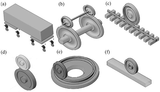
Figure 10.
Main types of wheel and rail test stands. (a) Full-scale vehicle wheel vs. rail wheel; (b) full-scale train wheel vs. rail wheel; (c) full-scale train wheel vs. straight rail; (d) reduced-scale twin-disk rig; (e) reduced-scale wheel vs. circular rail; (f) reduced-scale wheel disk vs. straight rail [48].
Due to the different scales of experiments, different experiments require different test benches. Naeimi et al. divided the wheel–rail test benches according to the experimental object into six categories, such as full-scale rolling stock-rail wheel, full-scale wheel–rail wheel, full-scale wheel-straight rail, scaled-down double-disk, scaled-down wheel-disk-straight rail, and scaled-down wheel-loop rail, etc. [48].
3.1. Wheel Track Experimental Simulation
Currently, the most widely used wheel and rail simulation experiment is the double-disk pair rolling experiment. Rolling fatigue experiments were conducted by using a double-disk testing machine. The principle of the twin-disc testing machine is shown in Figure 11, the test machine consists of a single or two motors combined with a drive shaft, which is controlled, and data is saved by a computer. Slip is achieved by the motors making a difference in the rotational speed of the specimen. At the same time, there is a hydraulic system to provide load conditions for the experiment, through the control of speed, slip, and load for the wheel–rail contact simulation experiment. The testing machine and specimen are arranged internally as shown in Figure 12.
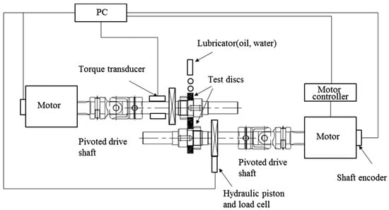
Figure 11.
Schematic diagram of the double-disk tester [49].
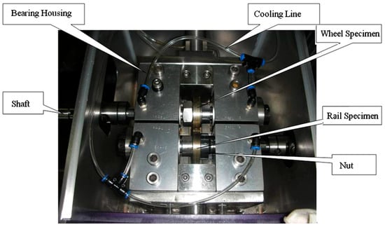
Figure 12.
Schematic diagram of the test machine and specimen [50].
Jung-Won Seo [50] conducted rolling contact fatigue tests on specimens cut from wheel rims and rail heads using a double-disk testing machine, the sampling method and specimen shape of the experiment are shown in Figure 13, and the tests were conducted under non-lubricated and lubricated conditions, respectively, to compare the time of crack emergence and growth of cracks on the contact surfaces of the two wheels and rails; under dry conditions with no lubrication, cracks started to appear on the surface of the rail specimens at 5 × 10⁵ cycles, and crack length and depth did not grow much after that, probably due to wear. Experiments under lubricated cracks began to appear at 7 × 10⁵ cycles and continued to expand, eventually leading to spalling; the hardness and microstructural changes in the rails under lubricated conditions were also investigated, with the rate of crack expansion first increasing and then decreasing.
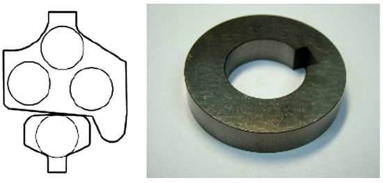
Figure 13.
Diagram of double-disk experimental specimen [50].
Double-disk-to-roll experiments are currently the main research method of wheel track simulation experiments, but in addition to double-disk-to-roll experiments, small-scale wheel track simulation experiments, full-size wheel track simulation experiments, line experiments and several experimental methods can also be used.
Small-scale wheel–rail simulation experiments have the advantages of safe operation and easy-to-control equipment, and are more economical and efficient [51]. Figure 14 shows several common types of scaled-down wheel-rail track test rigs. The scaled wheel–rail simulation experiment used in the small-scale wheel–rail simulation experiment can currently be categorized as scaled wheel–straight rail, scaled wheel–ring rail two types. The scaled wheel–rail simulation test bench is designed in accordance with the scaled-down ratio of the actual vehicle. Generally, the ratio to the actual train is 1:4 or 1:5 [52]. Due to the difference in size and wheel size with the actual vehicle, some parameters of the wheel track and force need to be adjusted accordingly in the experiment simulating the real situation, and the experimental results obtained also need to be further processed.
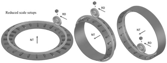
Figure 14.
Scaled-down wheel-ring track simulation test rig [48].
Full-size wheel–rail simulation experiments simulate the size of the actual wheel–rail system and operating conditions to analyze the dynamic behavior between the wheel and rail. A common full-size wheel-rail rolling test rig is shown in Figure 15. This experimental method is important for understanding the dynamics of wheel–rail systems, evaluating the performance of wheel–rail materials, and optimizing the design of wheel–rail systems [53].
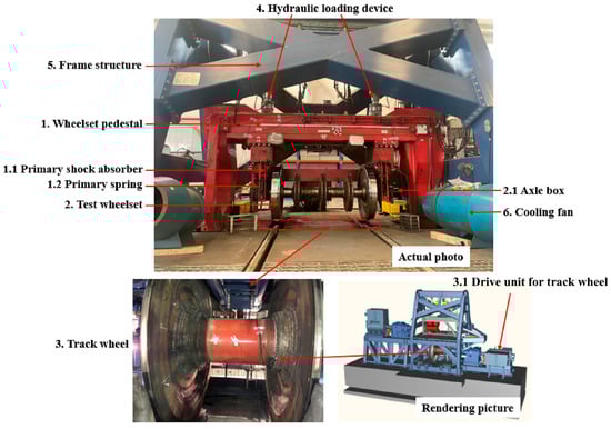
Figure 15.
Full-size wheel–rail rolling test bed [54].
Yue Wu et al. [54] reproduced the whole process of polygonal wear of CL60 steel wheels through a full-size wheel–rail rolling test machine, the full-scale wheel-rail test rig used in the experiment is shown in Figure 16. and found that wheelset bending resonance is a key factor inducing polygonal wear during wheel–rail operation. This resonance significantly enhances the dynamic forces on the wheel–rail and forms cyclic wear at specific wavelengths.
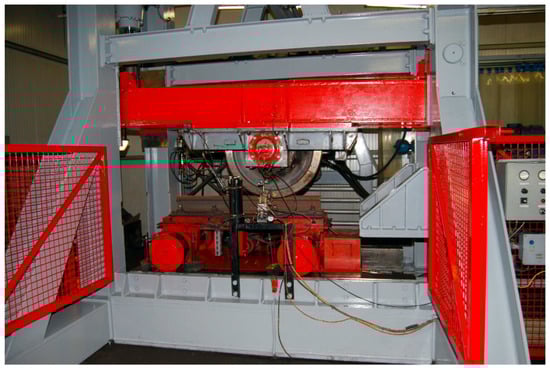
Figure 16.
Full-size wheel–rail test stand of Voestalpine Railway Technology Ltd. [53].
K. Oldknow et al. [55] tested three types of rails, R260, R350HT and R400HT, under dry conditions using the Voestalpine full-size wheel–rail test rig, collected detailed stress data on the wheel–rail surfaces, and concluded that higher-hardness rails reduce wear without increasing the tendency to RCF, but that the reduction in wear slows down the progression of the contact area towards conformality, which was verified by simulation.
The line experiment is a real wheel–rail operating environment, which can allow the performance changes in wheel–rail materials under actual use conditions to be studied in detail, and the results can be directly used in solving the manufacturing, maintaining, and repair of an actual wheel–rail. The data that can be directly applied include, but are not limited to, wheel rail wear, wheel rail adhesion, wheel rail contact stress, and wheel rail operation noise.
Gongquan Tao [56] et al. observed and measured 1472 wheels of 23 trains on metro lines in China, Figure 17 is a photo of a representative observed wheel tread. combined with kinetic model simulations, and found that wheel RCF is highly dependent on the wear pattern, and that trains passing through curves with radii greater than 600 m are susceptible to generating and extending RCF damage. Notch wear leads to higher contact pressure, and the increased hardness of the tread surface makes it difficult for RCF to be removed by abrasion. Corrugated wear on 60N rails and low rails of small radius curves also affects wheel RCF.
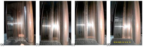
Figure 17.
Photographs of wheel tread (a) in good condition; (b) RCF cracked; (c) RCF crack + slight spalling; (d) spalling along the circumference of the wheel [56].
However, line experiments also have limitations: the cost of the experiment is usually very high and involves safety and scheduling issues; the experimental period is usually very long, and the experiment will have uncontrollable variables in the real situation. Therefore, line experiments can only be applied to a small number of topics.
3.2. Wheel–Rail Contact Fatigue
The contact stress–strain problem of wheel rails mainly refers to the rolling contact fatigue of wheel rail steel. Contact fatigue refers to the rail under the action of alternating stress, the contact surface or subsurface cracks and expansion, and the formation of surface spalling or penetrating cracks, resulting in the failure of components [57].
3.2.1. Rolling Contact Fatigue Cracks
Cracks are categorized according to the location of crack initiation:
Prolonged cyclic stress strains can lead to fatigue crack initiation and propagation in wheel and rail materials. It will affect the rolling contact fatigue performance of wheel rails. According to the location of crack initiation, Zhao Xin [58] and others classified the rolling contact fatigue of wheel rails into two categories: one is initiated on the contact surface; the other is initiated in the subsurface layer. The two types of rolling contact fatigue cracks are shown in Figure 18.
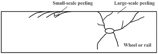
Figure 18.
Wheel–rail rolling contact fatigue emerging from the contact surface (left) and subsurface layer (right) [58].
The exhaustion of material ductility causes rolling contact fatigue on the surface, which is facilitated by conditions such as traumatic injuries, such as foreign body chipping and scratching, wheel abrasions, and geometric irregularities such as rail abrasion [59,60,61]. When cracks sprout in the wheel–rail contact region, they usually expand along the plastic flow direction of the material to the interior of the rail under contact loads. During this process, the angle between the crack and the surface increases gradually with the depth [58]. During the extension process, the main crack will form a bifurcation, and when multiple cracks penetrate through the crack, it will eventually form a peel [62].
In contrast to surface cracks, subsurface cracks are mainly affected by normal contact loads, and these cracks tend to originate at defects such as brittle inclusions and voids in the material [63]. After crack initiation, cracks expand both upward and downward, with upward expansion being more likely, and eventually end up peeling, but the volume of the peeled material is much larger than that of the surface-emerged one [58].
Classification according to crack distribution:
The fatigue distribution is categorized into continuous-type rolling contact fatigue, which occurs continuously along the contact surface and local-type rolling contact fatigue, which occurs locally. Continuous-type rolling contact fatigue occurs over most of the wheel tread, and Deuce [64] classified it into four categories based on the location of transverse occurrence, As shown in Figure 19, namely: category 1, most commonly found on the outside of the nominal rolling circle; category 2, present at the root of the rim and formed by the action of the wheel and the curved high bar; category 3, transverse cracks formed in the vicinity of the nominal rolling circle as a result of excessive longitudinal creep–slip; and category 4, transverse cracks formed in the vicinity of the nominal rolling circle as a result of excessive transverse excessive creep–slip, formed in the vicinity of the nominal rolling circle.
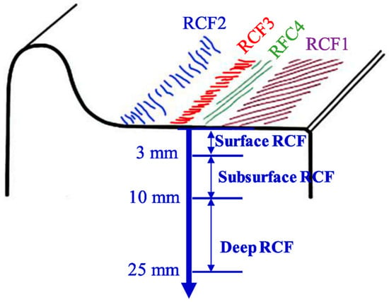
Figure 19.
Wheel continuous-type rolling contact fatigue classification [56].
Continuous rolling contact fatigue is common in curve sections with radii of 500~3000 m. This type of rolling contact fatigue belongs to the surface sprouting category, and due to the large creep–slip caused by the traverse of the wheelset when passing through the curve section and the change in gradient, it will lead to the emergence of rail shoulder diagonal cracks and gauge angles [65,66,67,68]. FLETCHER D I [67] discussed the fatigue and wear of rail surfaces, and their article details the effects of fatigue and wear on track surfaces are explored, including their definition, causes, and the impact of railroad operations.
The localized rolling contact fatigue of wheel and rail is highly related to the high-frequency wheel–rail action. Rolling contact fatigue occurring on wheels are called RCF clusters by Deuce [64], including the crescent-shaped cracks shown in Figure 20 and the squat on the rail shown in Figure 21, etc. [59,63,67]. It is common in straight lines and medium and large radius curves. At present, the emergence mechanism of localized-type rolling contact fatigue of wheel rails is still controversial, and both the surface and internal emergence mechanisms of this type of fatigue can be traced [69,70,71,72].
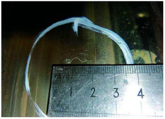
Figure 20.
Crescent-shaped cracks in wheels [58].
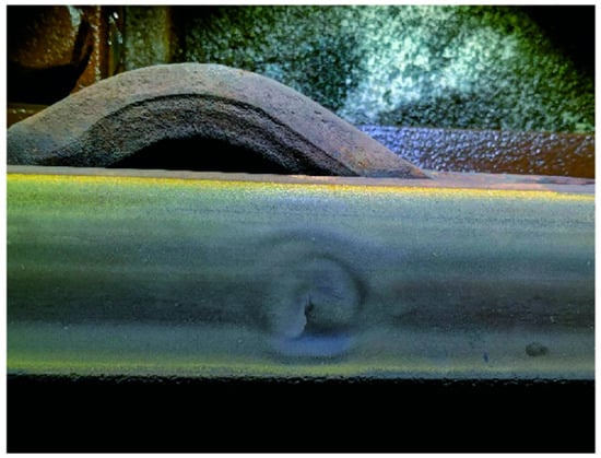
Figure 21.
Hidden injuries on subway tracks [58].
3.2.2. Wheel–Rail Temperature Field
Chen Shuai [73] and others published “The effect of tread braking temperature rise on wheel wear in heavy railroads”, in this paper, the effect of tread braking temperature rise on the hardness of wheels and rails was considered, and a wheel wear model for heavy railroads was established on this basis, and the change in tread temperature in the braking process was obtained through simulation and data fitting. The research on the effect of temperature on wheel wear was conducted, and the tread wear of the wheel was predicted. The results show that the temperature rise generated by friction during braking of the tread of heavy railroads increases wheel wear, and when the friction temperature rise is taken into account, the total wear volume of the wheel increases by 12.1%, and the maximum wear depth increases by 22.5% when the braking temperature rise reaches the highest.
An increase in wheel–rail contact temperature may increase wheel–rail wear and may trigger a phase change in the material, resulting in the formation of cracks on the surface of the wheel–rail, which may lead to damage to the wheel and material detachment. Even under steady state conditions at high speeds, the creep phenomenon between the wheel and rail can cause a significant temperature increase, which can soften the wheel and rail material and reduce the adhesion between the wheel and rail. Therefore, the study of the temperature rise in wheel rails under different operating conditions is of great value for practical applications.
3.3. Rolling Contact Fatigue Life Problems
There are many factors affecting the life of wheel rails.
(1). Material properties: the hardness, modulus of elasticity, strength limit and other properties of the wheel track material directly affect its service life, according to Zhuofan Xia [74] et al. In the rolling contact fatigue (RCF) failure mechanism of bearing steels with different levels of surface roughness under heavy loads, in which the surface roughness is one of the most direct factors affecting the life of the RCF, through experiments with samples with different surface roughnesses, the surface microstructure of the samples before and after service was analyzed in detail. The experimental results clearly show that the initial stage of formation of the collapsed structure and the nanocrystalline layer are the key factors leading to the shortening of the RCF life under the high-roughness condition to lower than that of the low-roughness condition. In addition, the spalling failure of low-roughness surfaces under heavy load conditions is mainly associated with the plastic deformation of the surface. R. Stock et al. [75] tested the wear and RCF behavior of several pearlitic and bainitic rails using Voestalpine’s full-size rolling relief fatigue tester, the changes in the wear amounts at different positions of different rails with the number of wheel-rail operations are shown in Figure 22, and found that the hardness of the rails with bainite does not have a significant effect on the fatigue performance, but the wear resistance of pearlitic rails is strongly related to and has a great relationship with the pearlitic hardness grade. And under the same hardness, the wear resistance of bainite rails is lower, but the fatigue resistance is stronger.
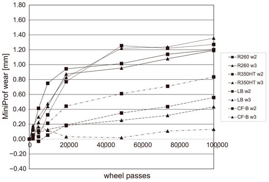
Figure 22.
Variation in wear volume at different positions of different rails with the number of wheel and rail runs [75].
Liu Qiyue [47] and others studied the surface fatigue performance of two types of commonly used rail materials, U75V and U75Mn. After different heat treatment methods, as can be seen through the surface fatigue damage of U75V rail material is significantly more than that of the rail material of U71Mn, and the fatigue performance of the rails using the quenching process has a certain gap compared with that of the hot rolled ones, and the differences in the microstructure of the wheel and rail materials may be one of the important reasons for the difference in the anti-surface fatigue performance.
(2). Geometry: The geometry of the wheel and rail, such as wheel diameter, gauge, rail type, etc., has a direct effect on the contact stress and wear rate. Suitable geometry design can reduce stress concentration and wear, thus extending wheel and rail life. Karttunen K et al. [60] studied the effect of track geometry irregularities on rolling contact fatigue. Track geometry data obtained from field measurements were used in the study, and lateral irregularities were extracted and scaled to represent different degrees of geometric deterioration (Figure 23). Multi-body simulations of dynamic train–track interactions were performed, and it was concluded that moderate lateral track geometry irregularities lead to normal track deflection forces, while increased irregularities lead to a complex relationship with rolling contact fatigue damage, which is due to the lateral movement of the contact point caused by track irregularities.
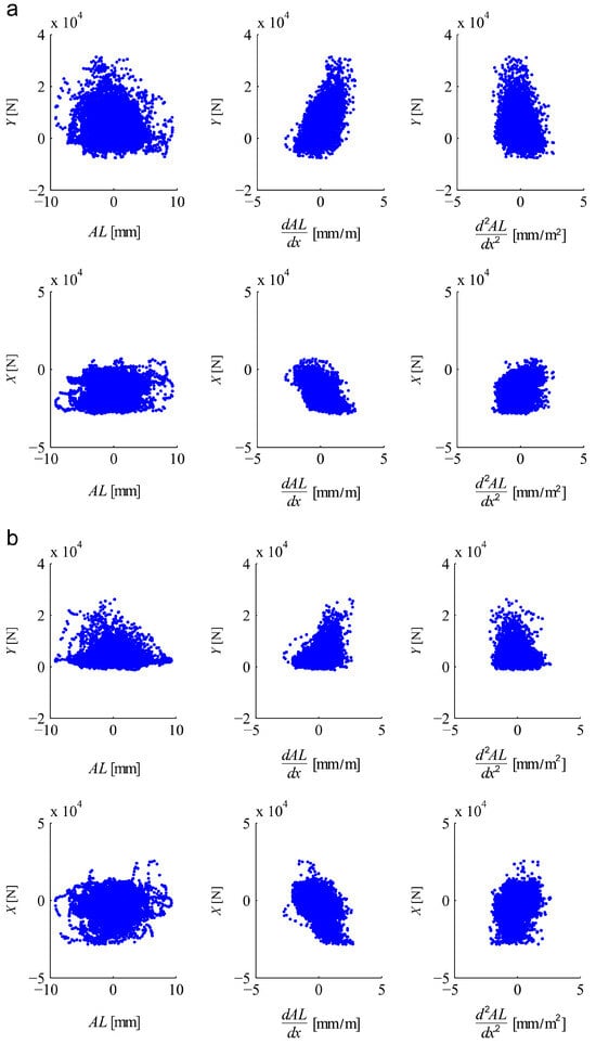
Figure 23.
Correlation of lateral (Y) and longitudinal (X) forces on the outer wheel (of the leading axle of the first bogie) for high level of lateral irregularities (AL) and their derivatives. Curve radius (a) 1000 m; (b) 3000 m [60].
(3). Load and speed: In a train in the process of operation, load and speed changes will lead to changes in the wheel–rail contact stress. Heavy load and high speed will increase the wheel rail contact stress, accelerate wear and shorten the life of the wheel rail. Among them, high-speed damage to the rail is mainly concentrated in rolling contact fatigue. In the case of high-speed trains running at high speeds, while in the braking process, a large amount of heat will be generated by friction, which exacerbates fatigue, stripping and other failure problems [76,77].
The results (Figure 24) show [78] that the effect of tangential force on the uneven longitudinal wear of rails is greater than that of normal force. When the tangential force is the same, uneven longitudinal wear of rails occurs under small normal force conditions. As the normal force increases, the wear rate decreases.
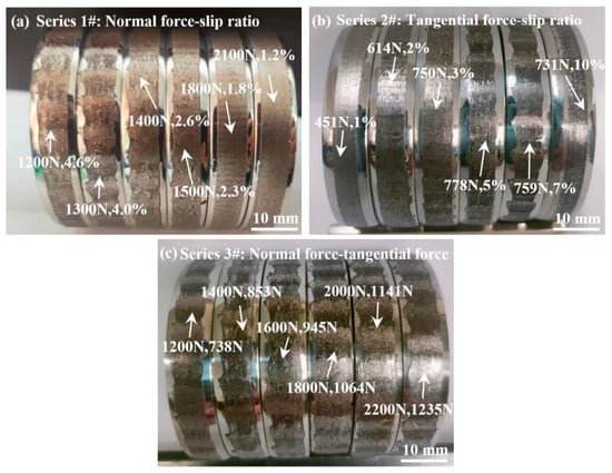
Figure 24.
Macro-morphology of the worn rail surface: (a) series 1#: same tangential force; (b) series 2#: same normal force; (c) series 3#: same slip ratio [78].
(4). Temperature: Temperature is a non-negligible influence on rolling contact fatigue of wheel tracks. The temperature field is one of the important factors affecting the stress and strain distribution in the wheel–rail contact area.
However, so far, the actual measurement of temperature in wheel–rail contact is still very difficult, so most of the studies on temperature rise in wheel–rail contact still focus on the theoretical calculation of temperature rise for various wheel loads, vehicle speeds and sliding speeds. Pei Youfu [79,80,81,82] and others studied the temperature rise in wheel–rail contact in the last century by using the transformation-based semi-analytical solution method, which has some engineering significance, but there are more assumptions made in the solution process, the model is more rough, and the obtained solution is basically of a qualitative level. Therefore, the finite element method can be used to analyze the wheel–rail temperature rise problem in order to reduce certain assumptions, increase engineering credibility, and applicability.
K.D. Vo, A.K. Tieu, H.T. Zhu, and P.B. Kosasih [83] jointly investigated the effect of railroad track damage due to high temperature under high-adhesion conditions. The study analyzed the effect of temperature, plastic strain, residual stress and other parameters on track damage by simulating wheel–rail contact under different conditions (Figure 25). The temperature distribution on the surface and cross-section of the track under different conditions is summarized by simulation analysis.
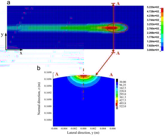
Figure 25.
Temperature contours (°C) on rail surface and cross-section. (a) Rail surface. (b) Cross-section A-A [83].
During the process of wheel–rail contact, wear between the wheel and rail is intensified. For wheels with limited contact area, thermal load becomes concentrated within a confined region, followed by rapid cooling due to ambient air and contact with the rail. This may trigger material phase transformation, causing part of the wheel steel’s microstructure to transition from pearlite–ferrite to martensite, thereby altering the steel’s properties and promoting the formation of surface cracks on the wheel and rail. Consequently, this leads to wheel damage and material spalling.
O. P. Ostash [84] employed traditional KP-2-type steel and high-strength, high-hardness KP-T-type steel produced in Ukraine as wheel materials. By analyzing the temperature dependence of strength and plasticity in these two types of steel, it was found that the mechanical properties of different steel grades—particularly at elevated temperatures—exhibit significant differences compared to their performance at room temperature as shown in Figure 26. The strength and plasticity at high temperatures provide more relevant reference values for studying defects induced by rolling contact fatigue.
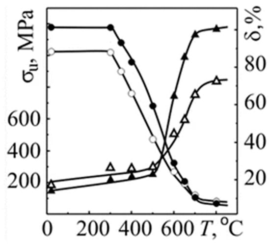
Figure 26.
Temperature dependences of the strength (○, ●) and plasticity (Δ, ▲) characteristics for 2 (○, Δ) and T (●, ▲) steels.
When a train operates in extremely cold environments, the temperature at the wheel–rail interface can drop significantly. At low temperatures, the properties of both rail steel and wheel steel undergo notable changes. Liu Qiyue et al. [48] studied the fatigue damage behavior of the rail material at room temperature and low temperature operation; the results show that: At room temperature, surface cracks in rail steel nucleate and undergo subcritical propagation at a shallow inclination angle. Under low-temperature conditions (−60 °C), however, cracks exhibit a markedly steeper inclination angle relative to the surface and demonstrate primary bifurcation during propagation. Upon attaining a critical depth, secondary bifurcation occurs, with subsequent crack advancement proceeding both into the bulk material and parallel to the surface. This distinct shift in crack propagation morphology is directly linked to the low-temperature embrittlement transition of the rail material.
The conditions of use: wheel rails in different conditions of use, such as temperature, humidity, environmental cleanliness and other aspects of change, may have an impact on their life. Poor environmental conditions, such as high temperature, humidity or corrosive substances containing the environment, will accelerate the corrosion and wear of wheel rails. Materials under low-temperature conditions deteriorate in terms of strength and toughness, so there is a large gap between damage behavior of wheel–rail materials under low-temperature conditions and at room temperature.
4. Computational Simulation of Rolling Contact Fatigue on Wheel Tracks
Due to the booming development of high-speed railroads in recent years, the research in the field of rolling contact fatigue calculation and the simulation of wheels and rails is also very active. Since the mid-1950s, a large number of dynamics analysis software has been developed at home and abroad. With the rapid development of computer technology, combining the latest developments in rigid and flexible multi-body dynamics theory and the results of computer applications to solve the dynamics of complex systems and kinematics analysis, the synthesis of the problem has become a new direction of the development of the wheel–rail rolling fatigue calculation and simulation software. Wheel–rail rolling contact fatigue calculation and simulation software is usually used to study the interaction between the wheel and rail, contact stress and fatigue life during train operation. This kind of software can be based on finite element analysis (FEA) or other numerical methods to simulate and analyze the rolling contact process in detail [85].
4.1. Introduction to the Software
In the development of rolling stock dynamics analysis software, there are many representative analysis software, which, combined with domestic and foreign technology, is explained chronologically by the following.
Commercialized Engineering Simulation Dynamics Software
(1) ANSYS software (ANSYS 2020R1)
In 1970, the commercial version of ANSYS was officially released. ANSYS is a large-scale general finite element analysis software widely used in the engineering simulation field(Figure 27), which can include the study of a wide range of fields, including structural mechanics, electromagnetic electric power, thermodynamics, acoustics and so on, and its application in wheel rail is very extensive [86].
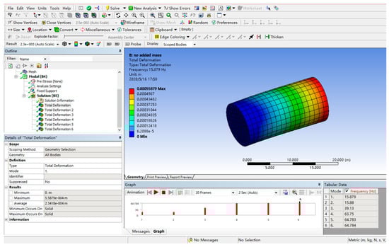
Figure 27.
ANSYS operator interface.
In wheel rail, ANSYS provides advanced fatigue simulation functions, including vibration fatigue, high-temperature fatigue, weld fatigue, etc., which is very important for the prediction of the fatigue life and the reliability of the wheel rail system. ANSYS is also capable of multi-physics field coupling analysis [87], which is very helpful for the understanding of the complex interactions in the wheel rail system. One of them is ANSYS Motion, a flexible multi-body dynamics analysis tool provided by ANSYS, which can be used for gear, track and chain modeling, as well as automotive kinematics analysis, which is very helpful for the dynamic simulation of wheel–track systems.
Compared to other multi-body dynamics software, ANSYS constitutes an extensive ecosystem of simulation software that encompasses multiple physical fields such as fluid, structure, electromagnetics, and semiconductors. Its greatest strength lies in its platform-based integration capabilities. However, such platform-oriented design can be overly complex when addressing problems within a single physical field and often lacks sufficient depth in highly specialized domains.
Guo Jia [88] used ANSYS finite element software to establish a three-dimensional wheel–rail solid finite element model, on the basis of which the wheel–rail contact stresses under different operating parameters and wheel–rail material properties were studied. The study shows that the axle weight has a great influence on the contact spot shape, area, normal contact pressure, maximum Mises stress and maximum XY shear stress of the wheel–rail contact area; with the increase in the punch angle, the position of the wheel–rail contact point changes, and the shape of the wheel–rail contact spot, the maximum normal contact pressure of the wheel–rail contact area, the shape of the contact spot, the area of the contact spot, and the contact stress change, but there is no specific pattern. However, there is no specific pattern that is related to the change in the geometry of the tread–rail contact. The maximum normal contact stress, contact patch shape, contact patch area, and maximum XY shear stress in the wheel–rail contact zone changes very little after the angular velocity of wheel rotation is applied, while the maximum Mises stress changes somewhat.
(2) ABAQUS software (Abaqus 2020)
ABAQUS was officially released by HKS in 1978, and in the 1980s, the software began to be used in vehicles. ABAQUS [89] is a powerful finite element software package for engineering simulations that solves problems ranging from relatively simple linear analyses to many complex nonlinear problems. ABAQUS includes a Component library that can simulate arbitrary geometries. It also has a library of various types of material models to simulate the properties of typical engineering materials, including a variety of materials with different structures.
Compared to other software, ABAQUS exhibits more robust nonlinear analysis capabilities and offers an extensive library of advanced and versatile material constitutive models. However, it also presents the drawback of a relatively steep learning curve.
Yi Qiang et al. [90] carried out finite element modeling of crack extension in turnout rails and numerical simulations by using ABAQUS and FRANC3D software, using the sub-modeling technique in FRANC3D to extract the finite element model of crack extension from the turnout switch panel built in ABAQUS (Figure 28). In the calculation process, the stress distribution was first calculated using ABAQUS. The obtained stress distribution data are then imported into FRANC3D for further crack extension simulation. Since the cracks are introduced into the sub-model in this process, co-simulation can be carried out by ABAQUS and FRANC3D software and finally verified with the experimental results to investigate the damage mechanism and crack extension behavior of the turnout rail.
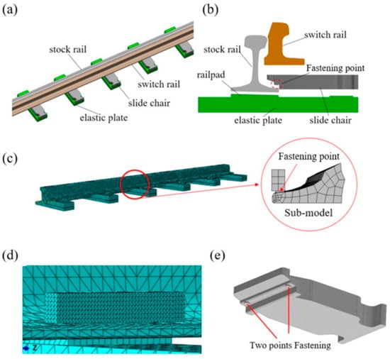
Figure 28.
Simulation model of the turnout (a) solid model; (b) model outline; (c) finite element model; (d) mesh refinement at fastening locations; (e) two-point fastening structure [90].
(3) SIMPACK software (SIMPACK 2019)
In 1985, SIMPACK software based on the relative coordinate system recursive algorithm developed by DLR [91] was introduced, focusing on multi-body dynamics modeling. SIMPACK is based on the time domain numerical integration technology and the relative coordinate system recursive algorithm, based on the computational dynamics of multi-body systems, including several professional modules and specialized areas of virtual prototyping system software, which realizes the coupling of rigid and flexible (elastic) bodies, creating a revolutionary development. It realizes the coupling of rigid body and flexible body (elastomer) and creates the revolutionary development of multi-body dynamics.
Compared to other software, SIMPACK excels in user-friendliness and openness, enabling seamless integration with software such as FEA and CAD tools. It supports rigid–flexible coupling analysis, which offers significantly higher accuracy than pure rigid-body models, thereby enhancing its overall analytical capability. However, SIMPACK demonstrates relatively weaker computational performance when addressing complex nonlinear static problems that are not primarily governed by dynamics.
Philipe Augusto de Paula Pacheco [92] used SIMPACK for modeling the dynamics and macro-geometry of rail vehicles for a heavy-duty railroad in Brazil (Figure 29). Objective functions and constraints are obtained from the dynamic simulation and used as input for the optimization algorithm, which then provides new wheel profiles as output (Figure 30).
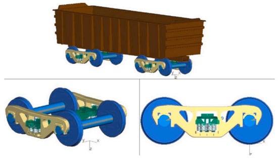
Figure 29.
Driving control GDU van built in SIMPACK [92].
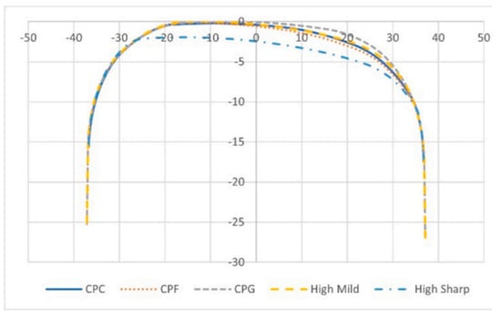
Figure 30.
Orbital contours used in SIMPACK [92].
The advantages of SIMPACK are that it is a very versatile tool; it can establish any track line, including track unevenness, line elasticity and track substructure; it can be combined with the Hertz inelastic contact theory and a variety of creep–slip force calculation models; the software interface is simple to operate; and it can establish a complete vehicle model.
(4) UM Software (UM 9.0)
UM software development work started in 1985, and in 1995, it established the direction of software development. Universal Mechanism (UM) is the world’s leading multi-body system dynamics simulation and analysis software [93] and can simulate any complex planar and spatial systems, which are widely used in aerospace, rail vehicles, wheeled vehicles, tracked vehicles, railroads, bridges and construction machinery and other industries. The most important feature of UM software is that it can display animations and draw curves while simulating dynamics (Figure 31), and can open any number of animation windows and drawing windows at the same time, so that users can observe the dynamics of each object in the system, such as displacement, velocity, acceleration, action and reaction forces and other performance parameters in real time.
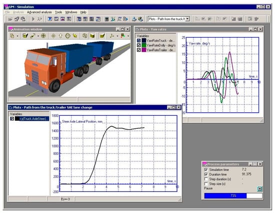
Figure 31.
UM simulation runtime interface.
UM software has modules including road vehicle modules, tracked vehicle modules, rolling stock modules, monorail modules, rigid–flexible coupling modules, 3D CAD interface modules, 1D and 3D train modules, wheel and rail wear modules, wheel rolling contact fatigue modules, fatigue durability analysis modules, flexible rail modules, etc. Compared with ordinary finite element simulation software, UM software has efficient and easy pre- and post-processing functions and supports parallel computing technology, easy model modification and high computational speed.
UM software represents a comprehensive railway vehicle simulation module that offers an integrated suite of tools for vehicle dynamics, wheel-rail contact, and system design. It incorporates standard wheelset subsystems and supports the input of track irregularity excitation through multiple approaches, enabling vehicle dynamics analysis based on such excitations. The module also provides professional tools for wheel-rail profile design and matching analysis, facilitating dynamics analysis, dynamic contact analysis, and visual inspection of wheel-rail dynamic interaction based on the profiles. Furthermore, UM supports the design of complex rail routes, optimization of vehicle geometric parameters, calculation of critical speeds, and multibody system dynamics solutions. It is capable of analyzing system natural frequencies, mode shapes, damping ratios, and root loci, and supports rigid-flexible coupling analysis of vehicle and axle systems. Additionally, the software includes fatigue analysis and life prediction for vehicle components and contains a standard variable library covering various vehicle dynamics performance indicators, thereby providing a complete workflow and data support for railway vehicle design and performance evaluation.
UM software provides interfaces for a variety of CAD software, which can import data directly from the kernel of the software, realizing seamless connection without data loss. It also supports the import of intermediate formats such as STEP, 3DS and ASC. In addition, UM has developed an ADAMS-UM interface, which makes it easy to import geometric models in ADAMS format into UM for dynamics analysis.
UM software has a lot of advantages over other software: UM is a software specialized in the simulation of railway vehicle and track dynamics, establishing itself as a preeminent authority in this field. In terms of wheel–rail contact, the software has a strong rigid–flexible symmetry system modeling technology, and powerful wheel–rail relationship processing functions, such as the real-time drawing of wheel–rail contact force curves at two points. However, beyond rail and track applications, it has limited applicability in other domains.
4.2. Time-Domain Simulation of Wheel–Rail Dynamics
Time-domain simulation of wheel-rail dynamics serves as a core approach for investigating the dynamic behavior of vehicle and track systems. By directly solving the system equations of motion in the time dimension, this method enables accurate simulation of time-varying nonlinear contact forces, vibrational responses, and dynamic instability processes between the wheel and rail. With the deepened integration of multibody dynamics software and finite element methods, time-domain simulation is advancing toward more refined applications such as rigid-flexible coupling analysis, wheel-rail wear prediction, and rolling contact fatigue life estimation. In the following, UM software will be employed as the solving tool to demonstrate a typical solution procedure for wheel-rail dynamic time-domain simulation.
4.2.1. Model Construction
Take UM software as an example. UM software can simplify the model of the vehicle-turnout system as necessary (Figure 32), establish the vibration equation of the vehicle and turnout system, and use multi-body dynamics software UM to establish the vehicle-turnout coupling system dynamics model on the basis of theory.
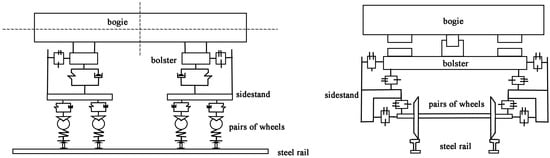
Figure 32.
Topology of the dynamic model of the railroad vehicle system.
In the development of the freight wagon model, the required number of degrees of freedom (DOF) for each component must be considered. The model DOF refers to the number of parameters that can still vary freely during the model parameter estimation process. The detailed DOF values for the vehicle are listed in the Table 1. A series of assumptions are made in the modeling process of the vehicle model, including treating the vehicle body, bogie and wheel pairs as rigid bodies and ignoring the elastic deformation.

Table 1.
Number of degrees of freedom for vehicle model.
Heavy-duty truck modeling can generally choose the simplest three major components of the bogie, as shown in Figure 33, mainly including wheel pairs, side frame, rocking pillow, bearing saddle, axle box rubber pads, tilt wedge, heart plate, constant contact elastic bypass bearings, cross tie rods and other components. The bogie can be combined with the carriage for railway vehicle modeling, as shown in Figure 34.
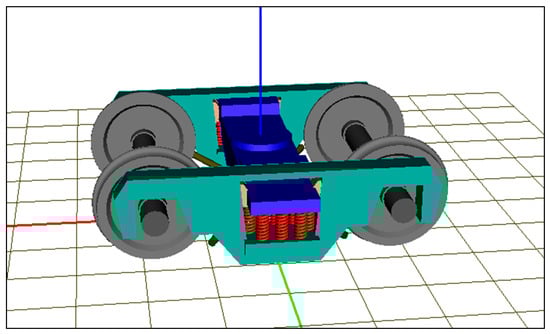
Figure 33.
Bogie modeling.
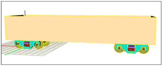
Figure 34.
Railway vehicle modeling.
4.2.2. Selection of Wheel and Rail Types
Set the corresponding rail parameters: Random track irregularity refers to the random deviation of the rail from its ideal position in terms of geometric parameters such as height, level, direction, gauge, etc., which is manifested by non-periodic fluctuations along the length of the rail. Track unevenness can be caused by many reasons, such as fastener failure, rail head wear, and construction errors.
The most commonly used numerical simulation methods for tracking random unevenness at home and abroad are the secondary filtering method, the triangular gradient method, and the white-noise filtering method, etc. For different track unevenness, reasonable filters need to be designed, thus becoming lacking in versatility [94].
Wheel–rail contact model: Due to the need for wheel–rail rolling contact calculation, the shape of the wheel tread is modeled according to the actual size without any approximation and simplification (Figure 35). The commonly used wheel treads in China are the standard LM-, LMA-, JM-, JM2-, JM3-type wear treads. The UM wheel tread is modeled with a local finite element model, and elastic constraints are imposed on each surface. The model supports the definition of the stresses in the inner unit of the contact surface, which ensures a sufficiently high accuracy and also allows for fast calculation and facilitates the cumulative calculation of contact fatigue damage at the nodes.
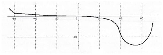
Figure 35.
Schematic diagram of wheel wear tread shape.
Set the railroad route: UM contains a wealth of architectural modules; it is easy to build complex railroad conditions, including but not limited to overheight, curve radius, gauge, track stiffness and other parameters.
It is also possible to import model data through CAD, FEM and other software so as to build models directly in UM.
4.3. Calculation Simulation of Wheel Track Life
The wheel track life calculation simulation is the most important part of the rolling contact fatigue calculation simulation.
In the simulation, the first necessity is to establish an accurate mathematical model through the software to describe the contact behavior of the wheel rail. This model needs to take into account the geometry of the wheel rail, material parameters, load conditions and other factors. This model is solved by numerical methods to obtain the stress distribution and fatigue life of wheel rails under different working conditions.
In practical application, the wheel rail rolling contact fatigue life calculation simulation and time domain simulation can help the railroad department to make more reasonable maintenance and replacement plans, and reduce the accidents and delays caused by wheel rail damage. At the same time, by simulating the performance of different materials and design options, it can also guide the development of new materials and new technologies.
4.3.1. Simulation Modeling Algorithms Applied to Lifetime Calculations
1. FASTSIM
The Fastsim algorithm, formulated by Kalker based on his simplified theory of rolling contact, is employed to determine the tangential stress field and the corresponding slip distribution within the rolling–sliding contact patch [95].
First, the kinematic equations for the stationary state are employed to calculate the dimensionless relative slip in combination with contact mechanics.
w = {υx − φy, υy + φx}, The rigid slip is referred to as the slip composed of the longitudinal, lateral creepage (υx, υy), and spin creepage components (φ), u = {ux, uy}.
Fastsim is based on the simplified theory of elasticity where the relation between the displacement due to elastic deformation of one point u(x,y) only depends on the tangential traction of this point p(x,y) = {px(x,y); py(x,y)}, L being the flexibility coefficient:
By combining both equations and assuming that the tangential tractions are known, the non-dimensional slip can be obtained.
The assumption is made that the coefficient of friction depends on the relative slip.
2. CONTACT
The Dutch company VORtech CMCC currently holds the copyright of CONTACT. The wheel–track CONTACT algorithm is an algorithm for dealing with collision detection between 3D objects and is mainly used to calculate the intersection between two geometries. Figure 36 is the operation interface of the CONTACT algorithm, the CONTACT software is capable of numerically solving both normal and tangential contact problems involving bodies with arbitrary geometries within the contact zone. This approach relies on a single fundamental assumption: the bodies can be modeled as elastic half-spaces when establishing the relationship between applied contact stresses and local deformations. Due to its high modeling accuracy and generality, CONTACT is widely used as a benchmark tool to validate and assess the precision of alternative contact models addressing similar problems. However, its significant computational cost makes it impractical for real-time or online contact calculations in multibody system (MBS) simulations [95].
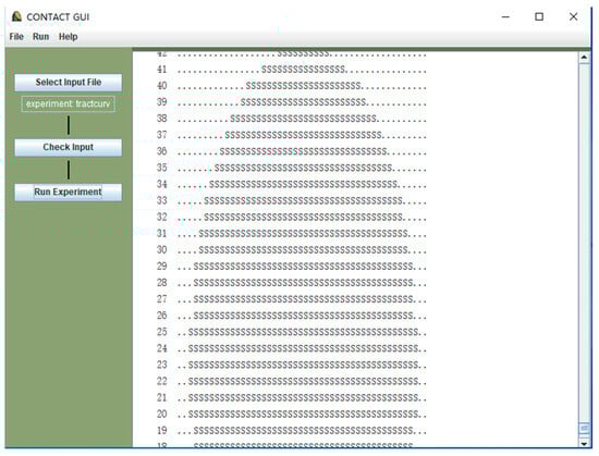
Figure 36.
User interface of the CONTACT software and representation of the contact patch.
3. FaStrip
The FaStrip algorithm is an efficient tangential contact solution method for wheel–rail interaction based on strip theory, designed to replace the traditional FASTSIM algorithm with the aim of improving the accuracy of local stress distribution, particularly for rolling contact fatigue (RCF) and wear prediction [96].
The FaStrip algorithm primarily addresses two major limitations of FASTSIM.
1. Traction Bound Shape: FASTSIM employs a parabolic traction bound derived from simplified theory, whereas FaStrip adopts an elliptical traction bound consistent with the Hertzian contact pressure distribution. 2. Stress Growth Pattern in the Stick Area: In FASTSIM, the shear stress increases linearly within the stick area; FaStrip, however, utilizes a nonlinear growth pattern, similar to Carter’s two-dimensional solution.
It is presumed that the material exhibits elastic–perfectly plastic characteristics. Based on the shakedown theorem and the Tresca yield criterion, plastic deformation occurs and surface cracks initiate at any location on the surface where the tangential stresses surpass the material’s shear yield stress. To implement this theory, stresses are computed using the FaS-trip algorithm and spread across the meshed contact area. Should the Tresca yield criterion be exceeded in any element, the RCF value for that element is increased by one. Similarly to RCF calculations under full-slip conditions, the RCF values are accumulated over the course of the simulations and adjusted proportionally to the lengths of the simulation curves.
It is used to evaluate the energy input at each point within the contact patch, serving as the key to coupling wear and RCF analysis [96].
where x and y are the profile coordinates, qx and qy are the tangential stresses in longitudinal and lateral direction, respectively, and νx, νy and φ are the longitudinal, lateral and spin creepages.
By comparing the local energy dissipation E(x, y) with the thresholds determined by material properties, the suppressing or removing effect of wear on RCF crack initiation is quantitatively considered [96]:
where and are the yield strength and ultimate tensile strength of the material, respectively, and is the corresponding resultant creepage threshold.
Long-term simulation results indicate that in the vicinity of the nominal rolling circle of the wheel, the use of FASTSIM leads to a significantly overestimated RCF prediction due to error accumulation (a difference of approximately 800,000 wheel revolutions). In contrast, the predictions from FaStrip show better agreement with five years of field observation data, particularly in terms of crack locations and angles.
4.3.2. Lifetime Calculation Simulation Steps
1. At the same time, domain of the same name is initially simulated through the corresponding data to establish a three-dimensional model of the wheel rail, the shape, material properties, the direction of the force, and the contact situation into the model.
2. The stress load value, the wheel- and rail-related speed settings, temperature, humidity, and other conditions are set to complete.
3. Run the simulation software to calculate the stress, strain and other physical quantities of the wheel rail under the given conditions and use these output results to evaluate the fatigue life of the wheel rail. Figure 37 shows the dynamic simulation process of rolling-contact fatigue in wheel-rail simulation.
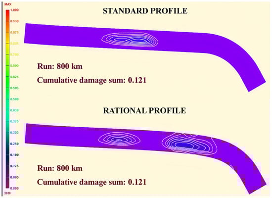
Figure 37.
Comparative calculation of the cumulative speed of wheel rolling contact fatigue damage using different tread surface cases.
4. According to the simulation results, use the fatigue life assessment methods (such as S-N curve method, Paris law, etc.) to estimate the fatigue life of the wheel and rail through the simulation results.as shown in Figure 38.
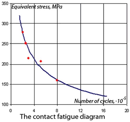
Figure 38.
Curve of equivalent stress vs. damage stress obtained through test data.
In practice, it may also be necessary to consider factors such as wear, corrosion, and cracking of the wheel and rail, as well as the effects of different operating conditions. In addition, several iterations and adjustments may be required to improve the accuracy of the simulation.
4.4. Measures to Improve Fast and Accurate Testing and Evaluation
Currently, there are many algorithms for rolling contact fatigue simulation calculation, which are divided into two categories.
One category is the algorithms based on finite element theory (FEM), which are widely used in rolling contact fatigue simulation due to their ability to handle complex geometries and material properties. This type of algorithm has high accuracy and can accurately simulate the nonlinear behavior of the contact interface, such as friction and elastic–plastic deformation. Strong versatility: This is applicable to rolling contact fatigue simulations of various materials and structures. Computationally intensive: It is computationally intensive because it is necessary to discretize the whole model and solve a large number of linear systems of equations. The following methods can be used to improve the calculation speed and accuracy of rolling contact fatigue simulations based on finite element theory.
A type of analytical model based on physical mechanism: The analytical model based on physical mechanism is usually based on the theories of mechanics of materials, fracture mechanics, etc., and describes the rolling contact fatigue process by establishing mathematical equations. This type of model is usually applicable to simplified or specific rolling contact fatigue problems. Simple modeling: The physical process of rolling contact fatigue is directly described by mathematical equations. Low computational effort: The computational effort is usually small compared to finite element methods. However, the scope of application is limited and is usually only applicable to specific rolling contact fatigue problems, such as fatigue life prediction models based on crack propagation.
The following are some suggestions to optimize and simplify the algorithm to improve the calculation speed and accuracy of rolling contact fatigue simulation.
1. Mesh optimization: Use adaptive mesh refinement technology to automatically encrypt the mesh in regions of high stress concentration or deformation to improve computational accuracy. Use a coarser mesh in unimportant areas to reduce the amount of calculation.
2. Choose appropriate material models and avoid using overly complex models to reduce the amount of calculation. For rolling contact fatigue simulation, you can focus on the elastic–plastic behavior of the material and the fatigue damage accumulation law.
3. Algorithm optimization: Adopt efficient solvers, such as a sparse matrix solver, to accelerate the solution of the linear equation system. Parallel computing technology is utilized to assign computational tasks to multiple processors or computers to speed up computation.
4. Contact algorithm optimization: For complex contact problems, consider using multi-scale or multi-physical field coupling simulation methods.
5. Fatigue damage model optimization: Choose a suitable fatigue damage model, such as stress-based, strain-based or energy-based model. According to specific application scenarios and test data, the fatigue damage model is calibrated and optimized.
6. Optimization strategy: Model calibration—calibrate and optimize the model parameters according to the test data and actual application. Introduction of new physical mechanisms—with the deepening of the research, new physical mechanisms can be introduced to improve the model.
5. Material Factors for Experimental/Computational Rolling Contact Fatigue Simulation
Summarizing the above experimental and computational simulations on rolling contact fatigue, both types of simulations seek to find the failure law during rolling contact fatigue by simulating the actual situation and establish systematic and data-oriented models and formulas. In wheel–rail contact simulation, researchers [18,78,94,97,98,99] have carried out a large number of studies including experimental and computational simulations on various physical parameters such as the wheel–rail matching relationship, curve radii, rail height, contact spot-type, contact force parameter, crack-type and crack initiation location, etc. For example, LI Zi-li [59] and others have carried out a transient finite element modeling to simulate the growth process of squats and predict the generation and development of squats. Predict the relationship between squat propagation and friction. It was also revealed that the growth of deep squat was related to some characteristic wavelengths of the wheel–rail interaction system, and the high-frequency vibration at the wheel–rail contact played an important role. Zhao Xin [100] studied the dynamic rolling contact problem of wheel–rail at squats (track discontinuity points). The rolling contact process of the wheel–rail was simulated by a dynamic finite element, which revealed the dynamic response of the wheel–rail at the hidden injury, and provided a scientific basis for track maintenance and damage prevention. However, in terms of wheel–rail contact, the consideration of the material itself is not sufficient; for example, there is a big gap in the study of the influence of different materials of rail steel on the fatigue life of rolling contact. In experimental simulation, although there are not many studies on the influence of rail material properties on rolling contact life, there have been some experiments on the chemical composition, heat treatment process and mechanical properties of rails [100,101]. However, for computational simulation, there is very little research in this area [101]. The wheel rail rolling contact fatigue software for the mechanical properties of the material parameter settings is not very comprehensive, and heat treatment process and chemical composition changes brought about by the software level are also difficult to reflect on.
5.1. Pearlitic Steel
Pearlite steel is one of the earliest uses of track steel, but also the most widely used rail material. Pearlite rail is characterized by the lamellar ferrite and carburite lamellae alternating with pearlite organization and a very small amount of ferrite organization. The birth of pearlite steel rail, so that the axle weight of the train can be doubled, marks the railroad traffic’s entry into the “rail era”. Pearlitic steel has gone through a gradual development from ordinary carbon steel to alloy steel rails, hot rolled steel rails, and the most widely used heat-treated steel rails [1]. Due to the excellent cost performance of pearlitic steel rail steel, pearlitic steel will still have more than half of the global new rail market share in 2022.
With the transportation requirements of strength, hardness and wear resistance and anti-rolling contact fatigue performance improvement, pearlitic steel rail has developed from sub-eutectic steel, to eutectic steel, to over-eutectic pearlitic steel, but with the continuous development of time, the traditional pearlitic steel rail material has reached the limit of development.
Liu Qiyue [47] and others researched different pearlitic steel rail materials and heat treatment on the surface fatigue damage behavior; the experiment through the U75V and U71Mn in which two kinds of pearlitic steel rail material were used for the dry state of the wheel–rail rolling contact surface fatigue damage behavior experiments. The study shows that the same pearlitic steel’s rail material fatigue performance is significantly better than the hot-rolled rail material and quenched rail material; for the two different pearlitic rail steels, reducing spacing of the pearlitic steel rail steel plate layers can effectively improve the fatigue performance of the material.
Masaharu Ueda [102] et al. found that the RCF resistance of pearlitic steel with 1.0% carbon content was significantly improved compared to that of 0.8% carbon content steel at the same initial hardness. The hardness of the rolling contact surface of pearlite steel gradually increases with the increase in carbon content. As shown in Figure 39, the crack inclination changes accordingly along with the decrease in the number of spalls and crack depth. This proposes a possible mechanism to inhibit the fatigue crack extension of high-carbon pearlite steel based on the fracture mechanics method.
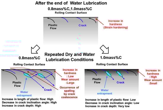
Figure 39.
Schematic representation of structural changes, crack extension behavior and spalling phenomena below the rolling contact (G.C.) region of the rail specimen [102].
Ziheng Shao [101] and others investigated the effect of alloying elements on the rolling contact fatigue (RCF) properties of pearlitic high-carbon wheel steels. The RCF failure process was analyzed, revealing that early severe plastic deformation (SPD) accumulation was the main cause of crack initiation. As shown in Figure 40, it is found that increasing the carbon content and vanadium microalloying can strengthen the wheel steel, reduce the accumulation of SPD, and inhibit crack initiation and expansion. The feasibility of using stability diagrams and fatigue indices for the rapid prediction of RCF performance was also demonstrated.
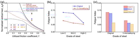
Figure 40.
(a) Stability diagrams for six wheel steels; (b) fatigue index FI versus carbon content for wheel steels; (c) effect of degree of vanadium microalloying [101].
At present, many basic theories of pearlite steel in rolling contact fatigue crack initiation and expansion mechanism, the relationship between the lamella spacing and mechanical properties, the phase transition theory and other basic theories have formed a more mature theoretical system, but the applicability of these theories are difficult to verify in some extreme cases and under multi-field coupling conditions.
In terms of computational simulation, although RCF computational simulation of pearlitic steel has made some progress in various aspects in recent years, it is still not able to simulate the rolling contact fatigue performance of pearlitic steel in complex environments. The fatigue behavior of pearlitic steel in wheel tracks is related to the microstructure, but almost none of the existing pearlitic models consider this aspect of correlation. H. Davoodi Jooneghani [103] et al. used a hierarchical mesh approach to achieve the first digital characterization of the multiscale organization of pearlitic steel, which lays the foundation for the simulation of fatigue crack anisotropic growth. Using SEM/EBSD experimental data and Voronoi surface subdivision, the study directly correlates the crack paths with the microscopic interfaces (grain boundaries, agglomerate boundaries, and carburite/ferrite interfaces) through a discrete element (DEM) soft-contact model, which compensates for the inadequacy of the existing FEM model that only considers the random organization, and proves that the deflection of the lamellar orientation due to plastic deformation can significantly change the crack extension rate. The mesh method can be coupled with CPFEM (grain-scale plasticity) or phase-field model (carburite dissolution) to solve the shortcomings of the traditional continuum model in describing the tissue evolution, and reveal the influence of tissue gradient (e.g., near-surface shear deformation zone) on the life of RCF.
5.2. Bainitic Steels
As a railroad track steel, bainitic steel is one of the ideal materials for manufacturing railroad tracks due to its high strength and good toughness, excellent wear resistance and resistance to rolling contact fatigue damage [1]. Bainitic steels excel in toughness properties with values up to 2–5 times higher than those of conventional pearlite steels. Thanks to the low carbon content of the design, the material shows excellent weldability and can be reliably welded to pearlite steels in existing lines. In terms of thermal stability, the bainitic organization has an advantage over pearlite, especially its higher austenitization temperature, which makes it resistant to peak temperatures and allows it to avoid the formation of case-hardened tissues over long sliding distances in wheel tracks. Although bainitic steel is still currently mainly in the laboratory research and development stage and it has not yet realized large-scale application, its excellent comprehensive performance highly matches the technical needs of heavy railroads, which will become the key research direction of the future development of rail materials.
The rolling contact fatigue performance of bainitic steel is closely related to its microstructural characteristics, such as bainitic ferrite (BF) slat thickness, residual austenite (RA) content and morphology. Bainitic steels are categorized into upper bainite, lower bainite and carbide-free bainite according to the location of carbide distribution and the morphology of its presence.
Li et al. [104] systematically investigated the effect of different cooling rates (30 °C/s vs. 0.3 °C/s) on the low-cycle fatigue properties of medium-carbon bainitic steels. At low strain amplitude, the fatigue life of the specimen with 30 °C/s cooling rate is longer, which is attributed to the TRIP effect to effectively resist plastic deformation; at high-strain amplitude, the stable high-carbon thin-film residual austenite in the specimen with a 0.3 °C/s cooling rate helps to impede the crack propagation and improve the fatigue life.
Zhang Ruijie [105] systematically summarized the effects of many material factors on rolling contact fatigue performance, analyzing the role of carbon content, inclusions and alloying elements. The study showed that bainitic steel with carbon content in the range of 0.2–0.3 wt% has excellent contact fatigue resistance; the influence of alloying elements on the rolling contact properties of bainitic steel is also very significant. U20Mn2SiCrMo air-cooled bainitic rail steel utilizes Si to inhibit the precipitation of carbides, and shows good wear resistance and crack tolerance in the trial laying of the Daqin Railway. Through their research, Zheng [106] and others found that a vortex-like plastic deformation zone is formed around the nonmetallic inclusions and leads to the generation of nanocrystalline regions, and fatigue cracks expand along the edges of the nanocrystalline regions. Experiments have shown that small-sized inclusions with a highly elastic modulus (e.g., Al2O3) are more prone to induce severe non-uniform plastic deformation, which in turn accelerates fatigue failure. The fatigue performance of steel can be improved by reducing such inclusions, and W. Solano-Alvarez experimentally observed that “butterfly”-shaped white etched zones appeared around the inclusions [107], and reverse fatigue cracks were generated on both sides, which seriously affected the fatigue performance of rail steel. Academic Zhang Fucheng’s group at Yanshan University found that replacing Si with Al can reduce the hydrogen embrittlement susceptibility of bainitic steel and improve its service life, and meanwhile, the service life of rutting forks was significantly improved by the development of high-aluminum nano-bainitic steel developed through isothermal treatment above the Ms point. Figure 41 shows the microstructure of the longitudinal section of carbon steel samples in carbide-free bainite after different cycles. The areas around the white dotted lines and white solid lines indicate severely deformed regions, while the white arrows point to vertical microstructures and nanocrystalline regions.
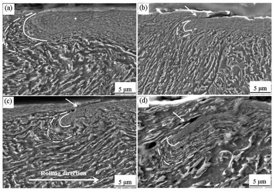
Figure 41.
Microstructure of longitudinal sections of carbide-free bainitic medium carbon steel specimens after different cycles. (a) 3.2 × 10⁴; (b) 1.1 × 10⁵; (c) 1.1 × 10⁶; (d) 7.6 × 10⁶.
In terms of computational simulation, rolling contact fatigue (RCF) studies of bainitic steels have revealed their damage mechanisms through multiscale modeling and numerical simulation [105]. Finite element analysis (e.g., ANSYS, ABAQUS) has been widely used to simulate the wheel–rail contact stress field, combined with models such as the Johnson stability diagram and the Burstow damage function method to quantitatively predict the fatigue crack initiation and extension behavior. In addition, the phase field method and molecular dynamics simulation have been used to investigate the kinetics of bainite phase transition and microstructure evolution, such as the mechanism of thin-film residual austenite retarding crack extension through the TRIP effect. However, the existing models still have limitations in simulating complex working conditions (e.g., multi-factor coupling, hydrogen embrittlement sensitivity), and further development of cross-scale coupling algorithms is needed to improve the prediction accuracy.
5.3. High-Manganese Steel
In wheel–rail contact, high-manganese steel has a long history. The most classical austenitic high-manganese steel appeared in 1882 [108]. Nowadays, more than 80% of railroad rutting forks in the world are made of high-manganese steel, and the failure problem of the rolling contact fatigue of high-manganese steel in railroads has been difficult to resolve.
In his research, Yang Shuai [109] focused on the high-manganese steel materials used in railroad rutting forks, explored different aging treatment techniques, implemented conventional thermal aging, plastic deformation aging and strain-induced aging treatment, and properties of high manganese steel after these aging treatments. In addition, he also made a detailed analysis of the work-hardening phenomenon and its rolling contact fatigue characteristics of high-manganese steel during aging treatment. As shown in Figure 42, Yang Shuai conducted a statistical analysis of the sub-surface hardness distribution curve of worn high-manganese steel frog, reflecting the hardness changes caused by the surface hardening of high-manganese steel. and utilized a variety of analytical tools to thoroughly investigate the evolution of the microstructure. For example, the transmission electron microscopy images of high manganese steel under different compression deformations shown in Figure 43.
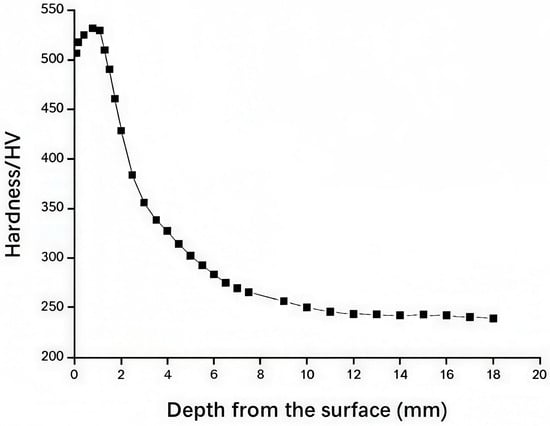
Figure 42.
Hardness distribution curve of the subsurface layer of failed permanganese steel rutting fork [109].
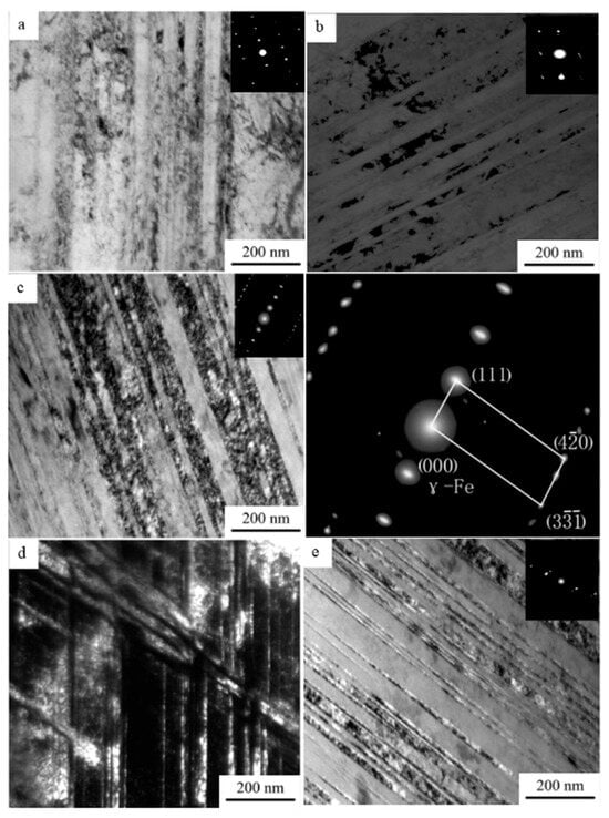
Figure 43.
TEM organization of high manganese steel with different compressive deformations. (a) 13%; (b) 16%; (c) 40%; (d) 40%; (e) 60% [109].
Dong Zhiguo [110] took the LM wheels passing through the No. 9 fixed rutting fork area made of high-manganese steel as the research object, and established a three-dimensional wheel–rail transient rolling contact finite element model with a real geometry by using ANSYS/LS-DYNA, and calculated the wheel–rail rolling contact behavior of wheels passing through the rutting fork area under the real situation in the time domain. Combined with the on-site investigation, the J-S fatigue crack initiation life prediction model was used to predict the fatigue crack initiation location and life of the rolling contact under different factors.
It is difficult for high-manganese steel wheel track experimental simulations to be systematic, or for data-formulated collated high-manganese steel tracks to be used in the operation of the actual situation, so high-manganese steel rolling fatigue calculation simulation experiments can be used to fill the vacancy in this regard. Like other rolling contact fatigue calculation simulations, the calculation simulation can be well-verified with the rolling contact fatigue experimental simulation, the experimental cost is lower, the retestability is better than the common experiments, the experimental variables can be better controlled, and the operability is strong. But at the same time, the work-hardening characteristics of high-manganese steel’s aging process will exponentially increase the work-hardening surface hardness; the high-manganese steel material’s volume will also change in the process. This dynamic change in the working conditions of the process will greatly increase the difficulty of the experimental simulation, although there are currently improvements to the calculation of the simulation program for the work-hardening properties of the high-manganese steel [101], but this is not a good solution to the calculation of the high-manganese steel track in this category of simulation problems. Therefore, how to completely simulate the rolling contact fatigue process of a high-manganese steel track through computational simulation, and how to obtain the corresponding curves and formulas are still urgent problems to be solved.
6. Conclusions
Wheel–rail rolling contact fatigue is a complex and important research field in railroad engineering, which is directly related to the safety and economy of train operation. In recent years, with the rapid development of high-speed railroads, the problem of wheel–rail rolling contact fatigue has become more and more prominent, which has attracted extensive attention from scholars at home and abroad.
From the early two-dimensional elastic rolling contact theory to the present three-dimensional non-Hertzian rolling contact theory, the theoretical model of wheel track rolling contact fatigue is constantly improving. These models can more accurately describe the contact behavior and stress distribution between the wheel rails and can more realistically reflect the stress distribution and plastic deformation of the wheel rail contact patch, providing a theoretical basis for subsequent fatigue life prediction.
Finite element method (FEM) and multi-body dynamics are the most commonly used numerical methods in the study of wheel–rail rolling contact fatigue problems. The fatigue life of wheel rails is predicted by simulating the rolling process of the wheel on the track and analyzing the stress distribution, material deformation and crack extension at the contact interface. Machine learning is beginning to be applied to fatigue life prediction, but it still needs to be supported by a large amount of experimental data.
The future wheel–rail rolling contact fatigue simulation calculations must continue in the direction of becoming faster, more accurate and better. This can be achieved through the following ideas.
(1) Experimental validation to improve the algorithm:
Experimental validation is an important means to ensure the reliability of theoretical models and numerical methods. Scholars at home and abroad simulate the wheel–rail rolling contact process by building an experimental platform, and observe and analyze the experimental results, which provides a basis for the improvement of the theoretical model and numerical method.
(2) Improvement of the three-dimensional elastic–plastic rolling contact theory and numerical methods:
The existing three-dimensional elastic–plastic rolling contact theories and numerical methods still have some limitations, such as large computational volume, poor modeling accuracy and other problems. In the future, these theories and methods need to be further improved to enhance simulation accuracy and computational efficiency.
(3) Development of a high-precision test device:
In order to more accurately simulate the wheel–rail rolling contact process, a true-sized test device with high-precision control performance and a testing system needs to be developed. This will help to determine the main factors affecting the fatigue damage of wheel rails and verify the accuracy of the 3D elastic–plastic rolling contact theory and numerical methods.
(4) Improvement and development of wheel rail materials:
The performance and structure of wheel rail materials have an important impact on the rolling contact fatigue life of wheel rails, and the influence of different compositions and different processing methods on the materials will greatly affect the various properties of the materials, and in the future, we need to continue to improve and develop the wheel rail materials and their anti-wear and anti-fatigue properties in the context of ensuring the comprehensive performance of the materials, so as to extend the service life of the wheel rails.
(5) Multi-field coupling under the action of fatigue research:
In practical applications, wheel and rail rolling contact fatigue problems are often subject to the coupling of multiple factors, such as temperature field, stress field, chemical field, etc. In the future, there is a need to study the fatigue problem under the action of multi-field coupling, reveal its influence mechanism and laws, and provide more comprehensive and in-depth theoretical support for the prediction and prevention of wheel rail rolling contact fatigue life.
(6) Application of AI and big data in fatigue problems:
Case studies are conducted through big data and AI deep learning, and the model algorithm is optimized to establish a universal prediction model by using the macroscopic mechanical model and microscopic material property analysis. With the development of science and technology, big data and AI models advance rapidly, and combined with traditional technologies such as finite element simulation, they can deal with complex problems that could not be dealt with before, through which the digital model twin of rolling lifting fatigue components can be constructed, and dynamic life prediction can be achieved by updating the model parameters with real-time data. The use of AI and big data has enabled the application of rolling fatigue problems to be extended from a single lifetime to full life cycle management and prediction, but the high cost and long cycle time are still problems to be solved in the future.
Author Contributions
M.W.: Writing—review and editing, writing—original draft, investigation, data curation, formal analysis. H.S.: Supervision, conceptualization, methodology. Z.Y.: Supervision, methodology, conceptualization. C.C.: Visualization, investigation, methodology. C.Z.: Conceptualization, methodology, supervision, funding acquisition. B.L.: Supervision, methodology, funding acquisition. F.Z.: Conceptualization, methodology, funding acquisition. All authors have read and agreed to the published version of the manuscript.
Funding
This study was supported by Innovation Capacity Improvement Project of Hebei Province (No. 244A1002D).
Data Availability Statement
No new data were created or analyzed in this study.
Conflicts of Interest
The authors declare no conflicts of interest.
References
- Chen, C.; Kang, J.; Feng, X.; Wang, M.; Lv, B.; Yang, Z.; Zhang, F. Review on steels for railway tracks. Sci. Sin. Technol. 2025, 55, 369–396. [Google Scholar] [CrossRef]
- Wang, L.; Liu, Y.; Mao, L.; Sun, C. Potential impacts of china 2030 high-speed rail network on ground transportation accessibility. Sustainability 2018, 10, 1270. [Google Scholar] [CrossRef]
- Hua, M.; Chen, C.; Xiangyang, Q.; Junkui, L.; Bo, L.; Fucheng, Z. Effect of rolling temperature on microstructure evolution and mechanical properties of high carbon high manganese steel. J. Mater. Res. Technol.—JMRT 2022, 21, 319–329. [Google Scholar] [CrossRef]
- Liang, Z. Research on the Influence Mechanism of Low Temperature Environment on Rolling Wear and Contact Fatigue Damage of Wheel/Rail Materials. Ph.D. Thesis, Southwest Jiaotong University, Chengdu, China, 2022. [Google Scholar]
- Huang, W.; Zhang, Y.; Yin, D.; Zuo, B.; Xu, M.; Zhang, R. Using improved group 2 and linguistic z-numbers combined approach to analyze the causes of railway passenger train derailment accident. Inf. Sci. 2021, 576, 694–707. [Google Scholar] [CrossRef]
- Jin, X.; Shen, Z. Development of wheel-rail rolling contact mechanics. Adv. Mech. 2001, 31, 33–46. [Google Scholar] [CrossRef]
- Hertz, H. On the contact of elastic solids. Z. Reine Angew. Math. 1881, 92, 156–171. [Google Scholar]
- Zhou, H. Analysis of Creep Characteristics of Highspeed Wheel-Rail Based on Finite Element Method. Master’s Thesis, Dalian Jiaotong University, Dalian, China, 2022. [Google Scholar]
- Carter, F.W. On the action of a locomotive driving wheel. Proc. R. Soc. A—Math. Phys. Eng. Sci. 1926, 112, 151–157. [Google Scholar] [CrossRef]
- Vermeulen, P.J.; Johnson, K.L. Contact of nonspherical elastic bodies transmitting tangential forces. J. Appl. Mech. 1964, 31, 338–340. [Google Scholar] [CrossRef]
- Johnson, K.L. The effect of a tangential contact force upon the rolling motion of an elastic sphere on a plane. J. Appl. Mech. 1958, 25, 339–346. [Google Scholar] [CrossRef]
- Kalker, J.J. On the Rolling Contact of Two Elastic Bodies in Presence of Dry Friction. Ph.D. Thesis, Delft University of Technology, Delft, The Netherlands, 1967. [Google Scholar]
- Cooperrider, N.K. The hunting behavior of conventional railway trucks. J. Eng. Ind. 1972, 94, 752–761. [Google Scholar] [CrossRef]
- Jin, X. Study on Creep Theory of Wheel and Rail System and Its Experiment. Ph.D. Thesis, Southwest Jiaotong University, Chengdu, China, 1999. [Google Scholar]
- Hu, Y. Research on the Steady Rolling Wear of Wheels Based on Finite Element Modeling. Master’s Thesis, Southwest Jiaotong University, Chengdu, China, 2019. [Google Scholar]
- Ma, L.; He, C.G.; Zhao, X.J.; Guo, J.; Zhu, Y.; Wang, W.J.; Liu, Q.; Jin, X. Study on wear and rolling contact fatigue behaviors of wheel/rail materials under different slip ratio conditions. Wear 2016, 366–367, 13–26. [Google Scholar] [CrossRef]
- Zhang, J. A Study on Wheel/Rail Creep Theory by Using Finite Element Method. Ph.D. Thesis, Dalian University of Technology, Dailian, China, 2003. [Google Scholar]
- Xie, Y.; Wang, W.; Wang, Y.; Shi, Z.; Ding, H.; Guo, J.; Meli, E.; Rindi, A.; Yuan, J.; Lewis, R.; et al. Investigation on the influence of the slip at the wheel-rail contact patch on the shakedown limit of rail material. Eng. Fail. Anal. 2024, 166, 108881. [Google Scholar] [CrossRef]
- Chang, C. A Study on Wheel/Rail Rolling Contact Theory Based on Finite Element Method and Its Applying. Ph.D. Thesis, China Academy of Railway Sciences, Beijing, China, 2010. [Google Scholar]
- Jin, X.; Zhang, L. Comparison of important creep-force m odels in the analysis of w heel-rail rolling contact. J. China Railw. Soc. 1998, 20, 56–61. [Google Scholar]
- Jin, X.; Shen, Z. Rolling contact fatigue of wheel/rail and its advanced research progress. J. China Railw. Soc. 2001, 23, 17. [Google Scholar] [CrossRef]
- Kalker, J.J. Three-Dimensional Elastic Bodies in Rolling Contact; Springer Science & Business Media: Berlin/Heidelberg, Germany, 2013. [Google Scholar]
- Knothe, K.; Stichel, S. Rail Vehicle Dynamics; Springer International Publishing: Cham, Switzerland, 2017. [Google Scholar]
- Knothe, K. History of wheel/rail contact mechanics: From redtenbacher to kalker. Veh. Syst. Dyn. 2008, 46, 9–26. [Google Scholar] [CrossRef]
- Shen, Z.Y.; Hedrick, J.K.; Elkins, J.A. A comparison of alternative creep force models for rail vehicle dynamic analysis. Veh. Syst. Dyn. 1983, 12, 79–83. [Google Scholar] [CrossRef]
- Wöhler, A. Versuche über die festigkeit der eisenbahnwagenachsen. Z. Für Bauwes. 1860, 10, 160–161. [Google Scholar]
- Basquin, O.H. The exponential law of endurance tests. Am. Soc. Test. Mater. Proc. 1910, 10, 625–630. [Google Scholar]
- Brown, M.W.; Miller, K.J. A theory for fatigue failure under multiaxial stress-strain conditions. Proc. Inst. Mech. Eng. 1973, 187, 745–755. [Google Scholar] [CrossRef]
- Shimizu, S.; Tosha, K.; Tsuchiya, K. New data analysis of probabilistic stress-life (p–s–n) curve and its application for structural materials. Int. J. Fatigue 2010, 32, 565–575. [Google Scholar] [CrossRef]
- Miner, M.A. Cumulative damage in fatigue. J. Appl. Mech. 2021, 12, A159–A164. [Google Scholar] [CrossRef]
- Ji, Y.; Yao, W.; Xia, T. An Applicability Assessment of Linear Cumulative Fatiguedamage Rules. Mech. Eng. 2015, 37, 674–682. [Google Scholar]
- Shanley, F.R. A Theory of Fatigue Based on Unbonding During Reversed Slip; Rand Corporation: Santa Monica, CA, USA, 1953. [Google Scholar]
- Corten, H.T.; Dolan, T.J. Cumulative fatigue damage. In Proceedings of the International Conference on Fatigue of Metals, New York, NY, USA, 28–30 November 1956; Volume 1, pp. 235–242. [Google Scholar]
- Manson, S.S.; Halford, G.R. Practical implementation of the double linear damage rule and damage curve approach for treating cumulative fatigue damage. Int. J. Fract. 1981, 17, 169–192. [Google Scholar] [CrossRef]
- Kramer, I.R. A mechanism of fatigue failure. Metall. Trans. 1974, 5, 1735–1742. [Google Scholar] [CrossRef]
- Ray, A.; Patankar, R. Fatigue crack growth under variable-amplitude loading: Part i–model formulation in state-space setting. Appl. Math. Model. 2001, 25, 979–994. [Google Scholar] [CrossRef]
- Tao, C. Research of Fatigue Damage Analysis Method Based on Loading Sequences. Master’s Thesis, Northeastern University, Shenyang, China, 2010. [Google Scholar]
- Pengkun, G.; Angang, Z.; Hao, L. Review of life analysis methods. Automob. Parts 2020, 36, 110–112. [Google Scholar] [CrossRef]
- Coffin, L.F.J. A study of the effects of cyclic thermal stresses on a ductile metal. Ryūmachi 1954. [Google Scholar] [CrossRef]
- Manson, S.S. Fatigue: A complex subject—Some simple approximations. Exp. Mech. 1965, 5, 193–226. [Google Scholar] [CrossRef]
- Ince, A. A generalized mean stress correction model based on distortional strain energy. Int J Fatigue 2017, 104, 273–282. [Google Scholar] [CrossRef]
- Engelmaier , E. Fatigue life of leadless chip carrier solder joints during power cycling. IEEE Trans. Compon. Hybrids Manuf. Technol. 1983, 6, 232–237. [Google Scholar] [CrossRef]
- Gan, L.; Wu, H.; Zhong, Z. Fatigue life prediction considering mean stress effect based on random forests and kernel extreme learning machine. Int. J. Fatigue 2022, 158, 106761. [Google Scholar] [CrossRef]
- Zhang, J.; Ma, Y. Comparison of three fatigue crack growth rate models. Res. Explor. Lab. 2012, 4, 35–38. [Google Scholar] [CrossRef]
- Tasora, A.; Anitescu, M. A complementarity-based rolling friction model for rigid contacts. Meccanica 2013, 48, 1643–1659. [Google Scholar] [CrossRef]
- Seo, J.; Hur, H.; Kwon, S. Effect of mechanical properties of rail and wheel on wear and rolling contact fatigue. Metals 2022, 45, 630. [Google Scholar] [CrossRef]
- Liu, Q.; He, C.; Huang, Y.; Ma, L.; Wang, W. Research and prospects of simulation experiment on wheel/rail fatigue damage. J. Southwest. Jiaotong Univ. 2016, 51, 9. [Google Scholar] [CrossRef]
- Naeimi, M.; Li, Z.; Petrov, R.; Sietsma, J.; Dollevoet, R. Development of a new downscale setup for wheel-rail contact experiments under impact loading conditions. Exp. Tech. 2018, 42, 1–17. [Google Scholar] [CrossRef]
- Seo, J.; Jun, H.; Kwon, S.; Lee, D. Rolling contact fatigue and wear of two different rail steels under rolling–sliding contact. Int. J. Fatigue 2016, 83, 184–194. [Google Scholar] [CrossRef]
- Seo, J.; Kwon, S.; Lee, D.; Choi, H. Analysis of contact fatigue crack growth using twin-disc tests and numerical evaluations. Int. J. Fatigue 2013, 55, 54–63. [Google Scholar] [CrossRef]
- Jin, X.; Liu, Q. Wheel-Rail Tribology; China Railway Publishing House: Beijing, China, 2004. [Google Scholar]
- Huang, L.; Zhang, W.; Ma, Q. Design of rolling-vibration test bench for railway vehicles. Railw. Veh. 2007, 45, 5. [Google Scholar] [CrossRef]
- Chang, C.; Chen, B.; Cai, Y.; Wang, J. Experimental study on high-speed wheel-rail adhesion characteristics under water-lubricated conditions using a full-scale test rig. China Railw. Sci. 2019, 40, 8. [Google Scholar] [CrossRef]
- Wu, Y.; Wang, J.; Liu, M.; Jin, X.; Hu, X.; Xiao, X.; Wen, Z. Polygonal wear mechanism of high-speed wheels based on full-size wheel-rail roller test rig. Wear 2022, 494–495, 204234. [Google Scholar] [CrossRef]
- Oldknow, K.; Stock, R.; Vollebregt, E. Effects of rail hardness on transverse profile evolution and computed contact conditions in a full-scale wheel-rail test rig evaluation. Wear 2025, 560–561, 205589. [Google Scholar] [CrossRef]
- Tao, G.; Tan, M.; Yuan, X.; Wen, B.; Wen, Z. Influence of wheel wear on the rolling contact fatigue of metro wheels in the central area of the wheel tread. Wear 2025, 571, 205777. [Google Scholar] [CrossRef]
- Chen, Y.; Liu, D.; Fang, H.; Bai, B. Rolling contact fatigue of rail steel. J. Iron Steel Res. 2000, 12, 50–53. [Google Scholar] [CrossRef]
- Zhao, X.; Wen, Z.; Wang, H.; Tao, G.; Jin, X. Research progress on wheel/rail rolling contact fatigue of rail transit in china. J. Traffic Transp. Eng. 2021, 21, 1–35. [Google Scholar] [CrossRef]
- Li, Z.; Dollevoet, R.; Molodova, M.; Zhao, X. Squat growth—Some observations and the validation of numerical predictions. Wear 2011, 271, 148–157. [Google Scholar] [CrossRef]
- Karttunen, K.; Kabo, E.; Ekberg, A. The influence of track geometry irregularities on rolling contact fatigue. Wear 2014, 314, 78–86. [Google Scholar] [CrossRef]
- Grohmann, H.D.; Hempelmann, K.; Groß-Thebing, A. A new type of RCF, experimental investigations and theoretical modelling. Wear 2002, 253, 67–74. [Google Scholar] [CrossRef]
- Jin, X.; Zhang, J.; Wen, Z.; Li, F. Overview of phenomena in wheel/rail rolling contact fatigue. J. Mech. Strength 2002, 24, 250–257. [Google Scholar] [CrossRef]
- Cannon, D.F.; Edel, K.O.; Grassie, S.L.; Sawley, K. Rail defects: An overview. Fatigue Fract. Eng. Mater. Struct. 2003, 26, 865–886. [Google Scholar] [CrossRef]
- Deuce, R. Wheel Tread Damage—An Elementary Guide; Bombardier Transportation GmbH: Netphen, Germany, 2007. [Google Scholar]
- Cannon, D.F. An International Cross Reference of Rail Defects; International Union of Railways: Paris, France, 2003. [Google Scholar]
- Dollevoet, R. Design of an Anti-Head Check Profile Based on Stress Relief. Ph.D. Thesis, University of Twente, Tenschede, The Netherlands, 2010. [Google Scholar]
- Fletcher, D.I.; Franklin, F.J.; Kapoor, A. Wheel–Rail Interface Handbook; Lewis, R., Olofsson, U., Eds.; Woodhead Publishing: Cambridge, UK, 2009; pp. 280–310. [Google Scholar]
- INNOTRACK. Rail Degradation Algorithm; Corus Rail and Voestalpine Schienen: Berlin, Germany, 2009. [Google Scholar]
- Li, S.; Wang, X.; Dong, W.; He, Q.; An, B.; Wang, P.; Yang, B. Peridynamic analysis of rolling contact fatigue crack propagation in rail welding joints with pore defects. Int. J. Fatigue 2025, 190, 108612. [Google Scholar] [CrossRef]
- Zhao, X.; An, B.; Zhao, X.; Wen, Z.; Jin, X. Local rolling contact fatigue and indentations on high-speed railway wheels: Observations and numerical simulations. Int. J. Fatigue 2017, 103, 5–16. [Google Scholar] [CrossRef]
- Li, Z.; Zhao, X.; Esveld, C.; Dollevoet, R.; Molodova, M. An investigation into the causes of squats—Correlation analysis and numerical modeling. Wear 2008, 265, 1349–1355. [Google Scholar] [CrossRef]
- Xi, N.; Liu, F.; Zhou, Q.; Zhang, Y. Characteristics and development patterns of rail rolling contact fatigue defects. Phys. Test. Chem. Anal. (Part A Phys. Test.) 2005, 2005, 95–99. [Google Scholar] [CrossRef]
- Shuai, C.; Lei, W.; Heji, Z.; Zefeng, W.; Hengyu, W. Influence of tread braking temperature rise on wheel wear of heavy-haul railway. J. Mech. Eng. 2017, 53, 7. [Google Scholar] [CrossRef]
- Xia, Z.; Wu, D.; Zhang, X.; Wang, J.; Han, E. Rolling contact fatigue failure mechanism of bearing steel on different surface roughness levels under heavy load. Int. J. Fatigue 2024, 179, 108042. [Google Scholar] [CrossRef]
- Stock, R.; Pippan, R. RCF and wear in theory and practice—The influence of rail grade on wear and RCF. Wear 2011, 271, 125–133. [Google Scholar] [CrossRef]
- Shen, Z.; Zhang, W.; Jin, X.; Zeng, J.; Zhang, L. Recent advances in wheel-rail contact mechanics research. China Railw. Sci. 2001, 22, 14. [Google Scholar] [CrossRef]
- Bin, Z.; Xiuqin, F. Types and formation mechanisms of tread shelling in railway wheels and tyres. China Railw. Sci. 2001, 2, 73–78. [Google Scholar] [CrossRef]
- Zhang, H.; Ding, H.H.; Cui, X.L.; Wang, Y.; Han, Z.Y.; Meli, E.; Wang, W. Experimental investigation on the effect of contact forces on uneven longitudinal wear of rail material. Wear 2023, 532–533, 205108. [Google Scholar] [CrossRef]
- Pei, Y.; Jin, Y.; Wen, S. Finite element analysis of temperature rise in wheel-rail contact. China Railw. Sci. 1996, 17, 11. [Google Scholar]
- Pei, Y.; Jin, Y.; Wen, S. Investigation of temperature rise caused by wheel/rail sliding using laplace transform method. China Railw. Sci. 1995, 16, 7. [Google Scholar]
- Pei, Y.; Jin, Y.; Wen, S. Investigation of wheel-rail sliding-induced temperature rise via laplace transform (part i). Railw. Roll. Stock. 1996, 34, 30–32. [Google Scholar]
- Pei, Y. Study on Wheel-Rail Adhesion Mechanisms in High-Speed Railways. Ph.D. Thesis, Tsinghua University, Beijing, China, 1996. [Google Scholar]
- Vo, K.D.; Tieu, A.K.; Zhu, H.T.; Kosasih, P.B. The influence of high temperature due to high adhesion condition on rail damage. Wear 2015, 330–331, 571–580. [Google Scholar] [CrossRef]
- Ostash, O.P.; Anofriev, V.H.; Andreiko, I.M.; Muradyan, L.A.; Kulyk, V.V. On the concept of selection of steels for high-strength railroad wheels. Mater. Sci. 2013, 48, 697–703. [Google Scholar] [CrossRef]
- Liu, B.; Vollebregt, E.; Bruni, S. Review of conformal wheel/rail contact modelling approaches: Towards the application in rail vehicle dynamics simulation. Veh. Syst. Dyn. 2024, 62, 1355–1379. [Google Scholar] [CrossRef]
- Gharawi, M.A.; Saadoon, A.M.; Hmoad, N.R.; Albayati, A.H. Structural performance of rail connections: Experimental testing and finite element modeling. Results Eng. 2025, 27, 105997. [Google Scholar] [CrossRef]
- Yang, Y.; Wang, J.; An, W.; Cai, J.; Bai, H. Advances in prediction methods of wear of rails. Wear 2025, 564–565, 205676. [Google Scholar] [CrossRef]
- Guo, J. Research on Wheel-Rail Contact Conditions and Material Parameters of High-Speed Trains Based on ANSYS. Ph.D. Thesis, East China Jiaotong University, Nanchang, China, 2017. [Google Scholar]
- Pi, M.; Shi, B. Research Status and Development Review of Finite Element Software ABAQUS. In Proceedings of the 30th Academic Annual Meeting of the Beijing Society of Mechanics, Beijing, China, 24 March 2024; China University of Mining and Technology: Beijing, China, 2024. [Google Scholar]
- Yi, Q.; Liu, X.; Wang, S.; Chang, H.; Jiang, Z.; Wang, W. Failure mechanism and crack propagation behavior of turnout stock rail in high-speed railway. Eng. Fail. Anal. 2025, 167, 109026. [Google Scholar] [CrossRef]
- Huang, A. Dynamic Performance Simulation Study of a Rail Vehicle Based on SIMPACK. Master’s thesis, Kunming University of Science and Technology, Kunming, China, 2012. [Google Scholar]
- de Paula Pacheco, P.A.; Endlich, C.S.; Vieira, K.L.S.; Reis, T.; Dos Santos, G.F.M.; Dos Santos, A.A., Jr. Optimization of heavy haul railway wheel profile based on rolling contact fatigue and wear performance. Wear 2023, 522, 204704. [Google Scholar] [CrossRef]
- Zhao, Z.; Wei, K.; Ding, W.; Du, W.; Li, H. UM-SIMULINK co-simulation for the vibration reduction optimization of a magnetorheological damping steel-spring floating slab track. Constr. Build. Mater. 2021, 307, 124923. [Google Scholar] [CrossRef]
- Li, X. Analysis of High-Speed Railway Track Parameters and Study on Train Dynamic Characteristics. Ph.D. Thesis, Southwest Jiaotong University, Chengdu, China, 2011. [Google Scholar]
- Liu, B.; Bruni, S. Comparison of wheel–rail contact models in the context of multibody system simulation: Hertzian versus non-hertzian. Veh. Syst. Dyn. 2022, 60, 1076–1096. [Google Scholar] [CrossRef]
- Hossein-Nia, S.; Sichani, M.S.; Stichel, S.; Casanueva, C. Wheel life prediction model—An alternative to the FASTSIM algorithm for RCF. Veh. Syst. Dyn. 2018, 56, 1051–1071. [Google Scholar] [CrossRef]
- Gao, Y. Research on Wheel-Rail Matching Relationship and Asymmetric Rail Profile Optimization Method in Metro Curved Sections Under Operating Conditions. Ph.D. Thesis, Beijing Jiaotong University, Beijing, China, 2021. [Google Scholar]
- Fan, W.; Wang, W.; Hou, G.; Wang, X. Modeling and simulation of macro contact pressure for rail sanding belt grinding considering curvature matching factors. J. Mech. Eng. 2020, 56, 154–162. [Google Scholar]
- Zhao, X. Dynamic Wheel/Rail Rolling Contact at Singular Defects with Application to Squats. Ph.D. Thesis, Delft University of Technology, Delft, The Netherlands, 2012. [Google Scholar]
- Hao, X.; Wang, H.; Sun, X.; Wang, Y.; Zhang, F.; Zhao, J.; Wang, T. Enhancing dry sliding wear resistance of high-mn austenitic steel by adding n. Wear 2025, 562–563, 205635. [Google Scholar] [CrossRef]
- Shao, Z.; Zou, Q.; Zhu, Y.; Zhang, P.; Wang, B.; Xu, Z.; Gu, X.; Wang, Q.; Zhang, Z. Effect of alloy elements on the rolling contact fatigue performance of wheel steel. Mater. Sci. Eng. A Struct. Mater. 2024, 913, 147085. [Google Scholar] [CrossRef]
- Ueda, M.; Matsuda, K. Effects of carbon content and hardness on rolling contact fatigue resistance in heavily loaded pearlitic rail steels. Wear 2020, 444–445, 203120. [Google Scholar] [CrossRef]
- Davoodi Jooneghani, H.; Six, K.; Sharifi, S.S.; Poletti, M.C.; Trummer, G. Representation of the microstructure of pearlitic steels for DEM simulations of fatigue. Wear 2024, 540–541, 205228. [Google Scholar] [CrossRef]
- Li, Y.; Zhang, Y.; Long, X.; Zhu, R.; Wang, W.; Li, Y.; Liu, Z. Effect of undercooled austenite cooling rate on the low cycle fatigue properties of an austempering bainitic steel. Int. J. Fatigue 2025, 193, 108809. [Google Scholar] [CrossRef]
- Ruijie, Z.; Chunlei, Z.; Bo, L.; Wang, X.; Li, X.; Li, Y.; Zhang, F. Research progress on rolling contact fatigue damage of bainitic rail steel. Eng. Fail. Anal. 2023, 143, 106875. [Google Scholar] [CrossRef]
- Zheng, C.; Lv, B.; Zhang, F.; Yang, Z.; Kang, J.; She, L.; Wang, T. A novel microstructure of carbide-free bainitic medium carbon steel observed during rolling contact fatigue. Scr. Mater. 2016, 114, 13–16. [Google Scholar] [CrossRef]
- Solano-Alvarez, W.; Pickering, E.J.; Peet, M.J.; Moore, K.L.; Jaiswal, J.; Bevan, A.; Bhadeshia, H. Soft novel form of white-etching matter and ductile failure of carbide-free bainitic steels under rolling contact stresses. Acta Mater. 2016, 121, 215–226. [Google Scholar] [CrossRef]
- Dastur, Y.N.; Leslie, W.C. Mechanism of work hardening in hadfield manganese steel. Metall. Trans. A 1981, 12, 749–759. [Google Scholar] [CrossRef]
- Yang, S. Study on Aging of High Manganese Steel. Master’s Thesis, Yanshan University, Qinghuangdao, China, 2010. [Google Scholar]
- Dong, Z. Analysis of Rolling Contact Fatigue Crack Initiation in Metro Line 9 High Manganese Steel Fixed Frog. Master’s Thesis, Southwest Jiaotong University, Chengdu, China, 2021. [Google Scholar]


Disclaimer/Publisher’s Note: The statements, opinions and data contained in all publications are solely those of the individual author(s) and contributor(s) and not of MDPI and/or the editor(s). MDPI and/or the editor(s) disclaim responsibility for any injury to people or property resulting from any ideas, methods, instructions or products referred to in the content. |
© 2026 by the authors. Licensee MDPI, Basel, Switzerland. This article is an open access article distributed under the terms and conditions of the Creative Commons Attribution (CC BY) license.