Abstract
Laser powder bed fusion (LPBF) provides an effective method for the preparation of self-sealing powder damping components, but the introduction of cavities simultaneously leads to a decrease in the mechanical properties of the components. In order to achieve a synergistic improvement in the stiffness and damping performance of LPBFed self-sealing powder damping components, this paper designed and prepared TC4 alloy beams incorporating both self-sealing powder and lattice structures, characterized by their manufacturing quality, mechanical properties, and damping performance and established corresponding static and dynamic models. The results show that, as the diameter of the lattice struts increases, the stiffness of the self-sealing powder beams incorporating lattice structures increases, while the amplification factor and structural damping ratio decrease, eventually tending toward that of the solid beam. The changes in damping performance are related to the powder volume and the internal surface area. Compared to self-sealing powder beams containing only cavities, self-sealing powder beams incorporating lattice structures with strut diameters of 0.6 mm and 0.9 mm not only exhibit a significant improvement in stiffness but also demonstrate smaller amplification factors and larger structural damping ratios under 1 g and 2 g vibration inputs, achieving a synergistic enhancement of stiffness and damping. This study provides an effective reference for the regulation and optimization of the mechanical properties and damping performance of LPBFed self-sealing powder structures.
1. Introduction
Vibrations are widespread in fields such as aerospace, machining, and transportation, often causing fatigue failure, reduced machining accuracy, noise, and other hazards. Therefore, vibration reduction is very important [1,2,3,4]. Particle damping is a passive vibration reduction method that utilizes the friction and collisions between particles as well as between particles and the inner cavity wall to effectively dissipate vibration energy [5,6,7]. Traditional methods of implementing particle damping involve installing separate particle dampers on parts or machining cavities into parts and then refilling them with particles [8,9,10,11]. However, these methods disrupt the original structure of the parts and involve complex procedures. In recent years, the rapid development of laser powder bed fusion (LPBF) technology has provided an effective means for the preparation of particulate damping components [12,13,14]. On the one hand, LPBF offers extremely high design flexibility, enabling the printing of cavities of any shape and size at virtually any location on the part [15]. On the other hand, LPBF can directly incorporate raw material powder into the cavities during the printing process. Since integrating particle damping using LPBF does not significantly increase production time or cost, it is also referred to as “damping for free” [16]. The structure that achieves particle damping by directly encapsulating powder through LPBF technology can also be referred to as a self-sealing powder structure.
In current research, the use of LPBF to produce self-sealing powder damping components has been widely recognized. Hollkamp et al. [17] used LPBF to prepare IN718 beams containing unmelted powder and found that the damping performance of the particle-damped beams was significantly improved compared to that of solid beams, suppressing up to 95% of vibrations. Ehlers et al. [18] proposed design criteria for LPBF-fabricated particle damping components based on AlSi10Mg beams and described the effect of particle damping as a function of excitation force, cavity width, and cavity length. Their results showed that the damping of beams containing unfused powder particles was 20 times greater than that of solid beams, achieving broadband damping from 600 to 18,000 Hz. Ozcevik et al. [19] quantified the combined effects of unmelted powder volume, cavity number, and cavity location on the damping performance of LPBF IN718 particle damping beams, finding that the effectiveness of particle damping strongly depends on its location and volume. When unmelted powder is located near the region of maximum amplitude, the damping performance of specific modes significantly improves, and as the volume fraction of unmelted powder increases, damping generally increases. However, the introduction of cavities inevitably leads to a decrease in structural stiffness, and the larger the cavity ratio, the greater the decrease in structural stiffness [20]. Therefore, it is necessary to further balance the relationship between damping performance and mechanical performance.
It is worth noting that lattice structures are periodic structures composed of specific unit cell arrays, characterized by high porosity, high specific stiffness, a large specific surface area, and excellent design flexibility [21,22,23]. By integrating lattice structures into the cavities of self-sealing powder structures via LPBF, on one hand, additional support can be provided without significantly reducing the cavity volume, thereby enhancing stiffness. On the other hand, introducing lattices can increase the internal surface area, offering greater design flexibility for the inner walls [24,25,26], which may promote interaction between the powder and the inner walls and improve damping performance. Therefore, the integrated design of self-sealing powder beams incorporating lattice structures represents a potential approach for achieving synergistic regulation of stiffness and damping performance in LPBFed self-sealing powder structures. To the best of the authors’ knowledge, no related reports on LPBFed self-sealing powder beams incorporating lattice structures have been published to date.
This study aims to investigate the stiffness and damping properties of LPBFed self-sealing powder beams incorporating lattice structures, and to reveal how lattice geometric parameters influence their stiffness-damping properties and the underlying mechanisms. Therefore, self-sealing powder beams incorporating lattice structures with different lattice strut diameters were designed and fabricated using LPBF. Their fabrication quality was characterized via CT scanning, their mechanical properties were evaluated through three-point bending tests, and their dynamic response and damping properties were assessed using vibration table testing. Additionally, corresponding finite element models (static and dynamic response models) were established to elucidate the influence of lattice structures on stiffness and damping properties. This study provides a new approach and offers effective insights for regulating and optimizing the mechanical performance and vibration damping performance of LPBFed self-sealing powder components.
2. Materials and Methods
2.1. Beam Structure Design
The beam designed in this paper includes a cavity for enclosing powder and a lattice structure inside the cavity, as shown in Figure 1. The beam has a total length of 200 mm, a width of 32 mm, and a thickness of 5 mm. The cavity is located in the middle of the beam, with a wall thickness of 1 mm and dimensions of 15 mm × 15 mm × 30 mm. The lattice structures adopt a typical BCC configuration, with a unit cell size of 5 mm × 5 mm × 5 mm, arranged in a 3 × 3 × 6 array to fill the entire cavity. The strut diameters of the BCC lattice are designed as 0.6, 0.9, 1.2, 1.5, 1.8, 2.1, 2.4, 2.7, 3.0, and 3.3 mm, respectively, and are subsequently labeled as B0.6 to B3.3. The rationale for selecting the BCC lattice is that, as a well-established classic lattice structure, it not only exhibits excellent mechanical properties but also shows superior formability in LPBF. Additionally, for better comparison, a self-sealing powder beam without a lattice (referred to as Cavity) and a solid beam without a lattice or cavity (referred to as Solid) were designed. The theoretical powder volume, theoretical internal surface area of the designed beams, and the weight of the actual samples obtained by LPBF are shown in Table 1.
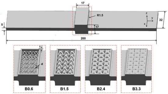
Figure 1.
Self-sealing powder beams incorporating lattice structures with different strut diameters.

Table 1.
Key Parameters of Different Beams.
2.2. LPBF Manufacturing
TC4 alloy powder (Micro-Nano Additive Technology Co., Ltd., Shenzhen, China) produced using the gas atomization method was used as the printing raw material, with its chemical composition shown in Table 2. The chemical composition of the powder was determined using a Plasma-3000 inductively coupled plasma atomic emission spectrometer (NCS-Micro Beams Co., Ltd., Beijing, China) and a CS5500 infrared absorption spectrometer (NCS-Micro Beams Co., Ltd., Beijing, China).
Table 2.
Chemical composition of powder raw materials.
The surface morphology of TC4 alloy powder captured by a SEM4000 scanning electron microscope (GIQTEK Technology Co., Ltd., Hefei, China) is shown in Figure 2a, where the majority of the powder particles have smooth surfaces and high sphericity. The particle size distribution of the powder measured by a Bettersize2600 laser particle size analyzer (Bettersize Instruments Ltd., Dandong, China) is presented in Figure 2b, with the majority of the powder particles having a particle size ranging from 20.42 to 59.86 μm. Different beams were fabricated using the EP-M300 industrial-grade metal 3D printing system (Eplus3D Technology Co., Ltd., Beijing, China). This system is equipped with a 500 W fiber laser with a wavelength of 1064 nm and a spot size of 0.08 mm. The printing process was carried out using the following parameters: laser power of 330 W, scanning speed of 1200 mm/s, scanning spacing of 0.12 mm, powder layer thickness of 0.03 mm, and energy density of 76.39 J/mm3. The energy density was calculated using Formula 1. The selection of this combination of process parameters is based on previous process optimization. The TC4 samples prepared under these parameters have excellent manufacturing quality.
where W is the laser power, v is the scanning speed, h is the scanning interval, and d is the powder layer thickness.
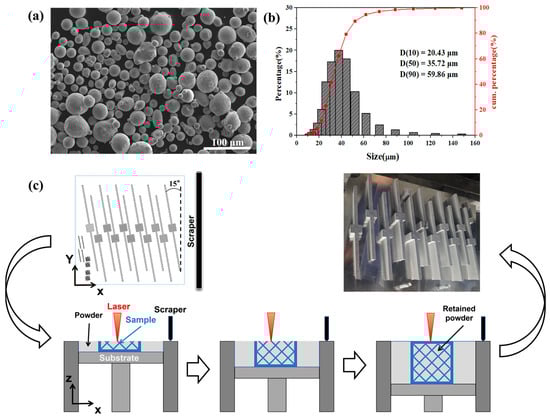
Figure 2.
Powder properties and the printing process of samples: (a) SEM image of TC4 powder; (b) Particle size distribution of TC4 powder; (c) Schematic diagram of the LPBF printing process for beams.
The printing process is carried out in a high-purity argon gas protective atmosphere, and a titanium alloy substrate is used. After printing, the sample is cut from the substrate using electric spark wire cutting. Figure 2c shows the printed layout model of the beams, a schematic diagram of the LPBF printing process, and images of the final samples obtained. During the printing process, the cavities of the beam are gradually filled with powder, which remains in place after printing to form a self-sealing structure.
2.3. Characterization and Testing
To verify the manufacturing quality of the self-sealing powder beams incorporating lattice structures prepared by LPBF, a multiscaleVoxel-1000 micro-CT (Sanying Precision Instruments Co., Ltd., Tianjin, China) was used to scan the central part of the beams, using an X-ray voltage of 180 kV and a scanning resolution of 17.5 µm.
To test the stiffness of different beams, a three-point bending test was conducted using a GNT600 electronic universal testing machine (NCS-Micro Beams Co., Ltd., Beijing, China) with a support span of 160 mm. The load was applied at a rate of 0.1 mm/min until 200 N was reached, after which the load was removed. The bending stiffness EI was calculated using Equation (2):
where F is the maximum load, y is the displacement of the pressure head at the maximum load, L is the span between the support points, and k is the slope of the stress–strain curve obtained from the test.
To test the damping performance of different beams, a sinusoidal sweep test was conducted using an EDS-300 electric vibration table (Econ Technologies Co., Ltd., Hangzhou, China). The beams were rigidly connected to the vibration table using special fixtures. An MI-2100 acceleration sensor (Econ Technologies Co., Ltd., Hangzhou, China) was fixed on the fixture as the input control, and another MI-2100 acceleration sensor was fixed at the top center of the beam as the output, as shown in Figure 3a,b. The sweep acceleration spectrum used in this study is shown in Figure 3c. The sweep frequency range was set to 10–2000 Hz. To investigate the damping performance under different acceleration excitations, the sweep acceleration was set to 1 g, 2 g, 3 g, and 4 g, respectively, and the sweep rate was set to 1.5 oct/min. After obtaining the output acceleration spectrum, the peak acceleration at different beam resonances was calculated, and the corresponding amplification factor K was determined. Additionally, the structural damping ratio ξ was adopted to further characterize the damping performance of different samples, and ξ was calculated by the half-power bandwidth method, as shown in Figure 3d. The corresponding formulas for K and ξ are shown as follows:
where aout is the peak acceleration at resonance, ain is the input acceleration, f0 is the resonant frequency, and fmin and fmax are the frequencies at the half-power amplitude points.
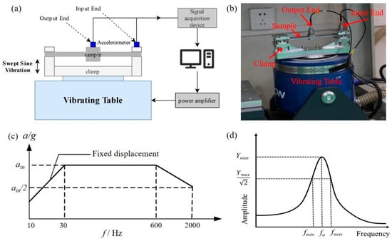
Figure 3.
Damping performance test method: (a) Principal diagram of vibration test system; (b) Actual image of vibration test system; (c) Sine sweep input spectrum; (d) The half-power bandwidth method adopted for calculating the structural damping ratio.
3. Modeling and Simulation
3.1. Static Simulation
Finite element simulations of three-point bending experiments on different beams were conducted using Abaqus. Since the beam deformation was extremely small, the powder inside the cavity had almost no supporting effect, so the influence of the powder was ignored in the static simulation. Additionally, since the beam did not undergo plastic deformation, only elastic constitutive models were used, with the corresponding material properties being a density of 4.5 g/cm3, a Young’s modulus of 110 GPa, and a Poisson’s ratio of 0.33. The relevant material parameters were obtained from tensile tests of TC4 samples printed using the same process. The tensile specimens were obtained by wire electrical discharge machining in the form of dog-bone-shaped plates, with a gauge length of 8 mm, a width of 2.5 mm, and a thickness of 1 mm. The surfaces were polished smooth with sandpaper. The tensile test was conducted using a GNT600 electronic universal testing machine (NCS-Micro Beams Co., Ltd., Beijing, China) equipped with a contact extensometer at a rate of 0.1 mm/min until specimen fracture. After the tensile test, the Young’s modulus of the TC4 samples was obtained by calculating the slope of the elastic segment of the stress–strain curve.
Three cylindrical rigid bodies were established to simulate the supports and the indenter in the three-point bending test, and contact relationships were defined between them and the beam. The tangential friction coefficient was set to 0.1. The reference points of the two cylindrical rigid bodies serving as supports were completely fixed, while the cylindrical rigid body serving as the press head was allowed freedom of movement only in the vertical direction (the Z-direction). A concentrated force of 200 N was applied downward (in the Z-direction) at the reference point of the press head to simulate the load applied by the press head. The beam was divided using C3D10M ten-node modified tetrahedral elements. The average mesh size of the two arms of the beam was set to 2 mm, and the average mesh size of the center cavity and lattice of the beam was set to 1 mm. The total number of meshes in the beam was approximately 500,000. This grid division method takes into account both computational efficiency and convergence. The boundary conditions and mesh division diagram are shown in Figure 4.
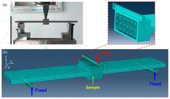
Figure 4.
Static simulation mesh and boundary conditions: (a) On-site diagram of the three-point bending experiment; (b) The mesh and boundary conditions of the finite element model.
3.2. Dynamic Simulation
The dynamic response of different beams was simulated. For the solid beam (Solid), the damping coefficient csolid of the TC4 material was set to 0.006. For the self-sealing powder beam without a lattice (Cavity), considering that the powder size in the cavity is extremely small (15–53 μm) and the number of powders is extremely large, traditional finite element-discrete element simulation methods are difficult to compute. Therefore, the powder is equivalent to a concentrated mass mpowder and is connected to the upper and lower surfaces of the beam cavity through spring dampers.
For self-sealing powder beams incorporating lattice structures, in addition to powder equivalence, the BCC lattice structure is also equivalent to a concentrated mass, mbcc, and is connected to the upper and lower surfaces of the beam cavity via spring dampers, as shown in Figure 5. Steady-state dynamics (direct method) in Abaqus linear perturbation analysis were used to perform harmonic response analysis on the beam, with a frequency range set from 10 to 2000 Hz. During the harmonic response analysis, the spring stiffness, kbcc, between mbcc and the upper and lower surfaces was set within the range of 28.72 to 868.69 N/m, and the damping coefficient, cpowder, between mpowder and the upper and lower surfaces was set within the range of 0.04 to 20, depending on the sample. Given that the material damping of the lattice itself is rather limited and the influence of powder on stiffness can be disregarded, cbcc and kpowder were ignored in the simulation. In this study, the damping resulting from the interaction between powders and the inner surfaces (including the surface of the lattice and the inner walls of the cavity) was combined and equivalent to cpowder. Additionally, the influence of the sensor was accounted for by setting a concentrated mass of 35 g at the top center of the beam. Acceleration inputs with an amplitude of 1 g were applied at both ends of the beam, and an output reference point was set at the sensor location.
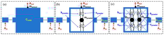
Figure 5.
Schematic diagram of dynamic simulation boundary condition settings: (a) Solid beam; (b) Self-sealing powder beam without lattice structure; (c) Self-sealing powder beam incorporating lattice structures.
4. Results
4.1. Forming Quality
Figure 6 shows the CT scan results of the two types of beams, B0.6 and B3.3, including reconstructed models with powder filtered out and reconstructed models with powder included. From the models with powder filtered out, it can be seen that the self-sealing powder beams incorporating lattice structures prepared by LPBF have excellent manufacturing quality, with no obvious defects such as pores or cracks. The lattice section shows no significant deformation of the struts, and there are no broken struts. From the models including powder, it can be seen that the cavities inside the beams are filled with powder, with no voids present. Additionally, due to the different lattice strut diameters, the powder content in the B0.6 sample is significantly higher than that in the B3.3 sample, consistent with the powder volume trend obtained from theoretical calculations in Table 1.
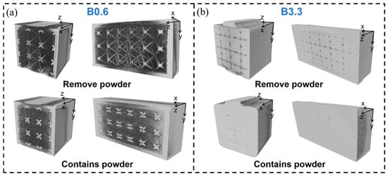
Figure 6.
CT scan results: (a) B0.6 sample and (b) B3.3 sample.
4.2. Stiffness
Figure 7 shows the displacement–load curves and corresponding stiffness values obtained from the three-point bending test for different beams. It can be observed that the stiffness of the solid beam (Solid) is 44.34 N·m2, while the stiffness of the self-sealing powder beam without lattice structures (Cavity) is 28.31 N·m2, representing a stiffness loss of over 36% compared to the Solid beam. It is worth noting that the bending stiffness of the self-sealing powder beams incorporating lattice structures designed for B0.6 to B3.3 are 33.42, 33.03, 35.60, 38.99, 42.44, 42.94, 41.03, 45.28, 44.46, and 43.15 N·m2, respectively, representing an improvement of over 17% compared to the Cavity samples. This demonstrates that the coupling of lattice structures can effectively enhance the stiffness of self-sealing powder beams.
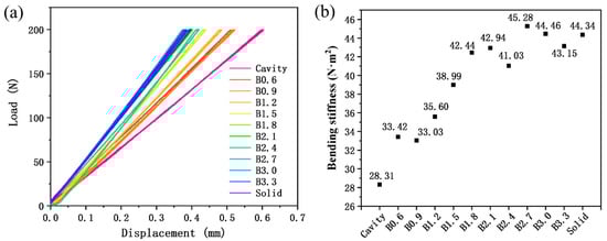
Figure 7.
Three-point bending results for different beams: (a) Displacement–load curve and (b) Bending stiffness.
Additionally, as the diameter of the lattice struts increases, the bending stiffness of self-sealing powder beams incorporating lattice structures shows a gradual upward trend. When the strut diameter exceeds 1.8 mm, the bending stiffness of self-sealing powder beams incorporating lattice structures differs from that of solid beams by less than 4%. Furthermore, the bending stiffness of the B0.9, B2.4, and B3.3 samples showed a slight decrease, while that of the B2.7 and B3.0 samples was slightly higher than that of the solid beam. This may be attributed to the residual stresses in the beams prepared by LPBF and the resulting slight bending of the beams. It is well known that the LPBF process features extremely high cooling rates and temperature gradients; thus, the TC4 samples fabricated by LPBF typically exhibit significant residual stresses [27]. The abnormal bending stiffness of some beams might be attributed to the slight bending caused by internal residual stresses.
4.3. Damping Performance
Figure 8 shows the acceleration–frequency response curves of different beams under sinusoidal sweep frequency inputs of 1–4 g. It can be observed that all beams exhibit a first-order resonance peak within the tested frequency range. When the vibration input is 1 g, the resonance frequencies of the Cavity, B0.6-B3.3, and Solid samples vary between 487 and 534 Hz. When the vibration input is 2 g, the resonance frequencies of the Cavity, B0.6-B3.3, and Solid samples vary between 485 and 544 Hz. When the vibration input is 3 g, the resonance frequencies of the Cavity, B0.6-B3.3, and Solid samples vary within the range of 484–544 Hz. When the vibration input is 4 g, the resonance frequencies of the Cavity, B0.6-B3.3, and Solid samples vary within the range of 502–533 Hz.
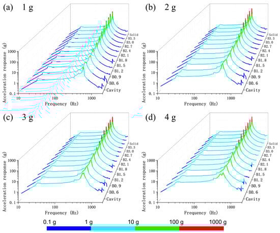
Figure 8.
Vibration response of different beams under acceleration inputs of 1 to 4 g. (a) 1 g; (b) 2 g; (c) 3 g; (d) 4 g.
It can be observed that as the strut diameter increases, the first-order resonance frequency of the self-sealing powder beam incorporating lattice structures shows a slight decreasing trend, which may be attributed to the gradual increase in sample mass. Additionally, as both the lattice strut diameter and input acceleration increase, the peak output response acceleration of the self-sealing powder beam incorporating lattice structures also increases accordingly. It is worth noting that compared to the solid beam, the B0.6 sample achieved acceleration peak reductions of 90.8%, 93.4%, 91.6%, and 90.5% at 1–4 g, respectively, indicating that an appropriate integration of lattice structures and self-sealing powder can effectively enhance the beam’s vibration damping performance.
To further compare the damping performance of different beams, the peak acceleration, amplification factor, and structural damping ratio of different samples were statistically analyzed, as shown in Figure 9. It can be observed that for the self-sealing powder beams incorporating lattice structures, as the lattice strut diameter increases, the peak acceleration and amplification factor also increase, while the structural damping ratio decreases. Among these, the B0.6 sample exhibits the lowest amplification factors (13.08, 12.59, 12.53, and 11.24 at 1–4 g) and the highest structural damping ratio (0.069, 0.053, 0.059, and 0.073 at 1–4 g), indicating the best vibration damping performance.
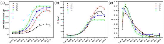
Figure 9.
Peak acceleration (a), amplification factor (b), and structural damping ratio (c) of different self-sealing powder beams.
When the strut diameter exceeds 2.1 mm, the amplification factor and structural damping ratio of the self-sealing powder beams incorporating lattice structures tend to align with those of the solid beam, indicating that the contribution of the powder to its damping performance becomes limited. Notably, at input acceleration amplitudes of 1 g and 2 g, compared to the cavity samples without a lattice, the B0.6 and B0.9 samples not only exhibit better stiffness but also have smaller amplification factors and larger structural damping ratio, demonstrating that the integrated design of the lattice and self-sealing powder can achieve synergistic improvements in beam stiffness and damping performance. In addition, for the Cavity sample and the self-sealing powder beams incorporating lattice structures with strut diameters greater than 2.4 mm, the same samples exhibited significantly different amplification factors and structural damping ratio under different acceleration amplitude inputs. This may be due to the different motion modes of the powder under different excitation conditions [28], which will be further investigated in subsequent work.
5. Discussion
5.1. The Effect of Lattice Structure on Bending Stiffness
To investigate the influence of the lattice structure on the mechanical properties of self-sealing powder beams, three-point bending finite element static simulations were conducted on different beam specimens. Figure 10 shows the bending stiffness of these beams obtained from the finite element simulation. It can be seen that the bending stiffness increases in the order of Cavity, B0.6, B1.5, B2.4, B3.3, and Solid samples. The simulation results are consistent with the experimental results, with a relative error of less than 5%, demonstrating that the established finite element model has excellent accuracy. Figure 11 shows the stress distribution cloud maps of different beams under a 200 N load. It can be observed that for the Cavity sample without a lattice, due to its minimal stiffness, it exhibits the greatest deformation, with the highest Mises stress occurring at the junction between the central protrusion and the two long arms at the ends. For the B0.6, B1.5, B2.4, and B3.3 samples, it is clearly evident that the lattice regions contribute to load-bearing, and the nodes of the lattice exhibit relatively higher Mises stress.
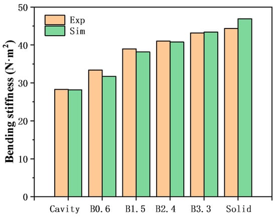
Figure 10.
Comparison of bending stiffness obtained from finite element simulation and experiment.
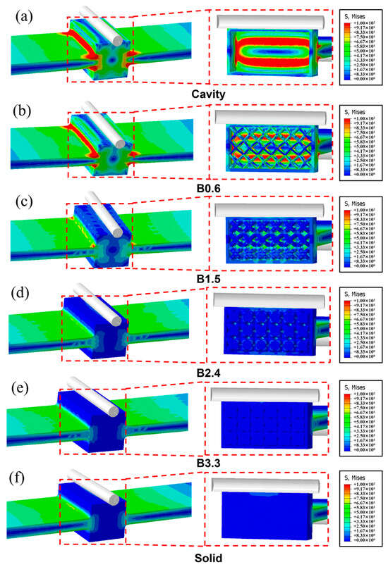
Figure 11.
Stress distribution cloud maps for different beams: (a) Cavity; (b) B0.6; (c) B1.5; (d) B2.4; (e) B3.3; (f) Solid.
It is worth noting that as the lattice strut diameter increases, the overall stiffness of the beam also increases, and stress concentration becomes less pronounced. This aligns with the Gibson-Ashby theory [20,21], which states that the mechanical properties of lattice structures are positively correlated with their relative density, lattices with higher relative density provide greater support for cavities. Additionally, the stress distribution of samples B2.4 and B3.3 is similar to that of the solid beam, consistent with the bending stiffness patterns shown in Figure 7 and Figure 10.
5.2. The Effect of Lattice Structure on Damping Performance
According to existing research, the damping performance of LPBF self-sealing powder structures is related to the size and shape of the cavity. The larger the cavity volume, the more inner surfaces that are orthogonal or at a certain angle to the excitation direction, the better the damping performance of the self-sealing powder structure [29,30,31,32]. In this study, as the lattice strut diameter changes, the volume of the powder and the interaction area between the powder and the inner wall also change, which in turn affects the damping performance of the beam. Figure 12 shows the variation in amplification factor and structural damping ratio of different beams with respect to powder volume and powder contact surface area. It can be seen that for self-sealing powder beams incorporating lattice structures, as the strut diameter increases, the powder volume inside the cavity gradually decreases, which directly leads to a decrease in damping performance, manifested as an increase in amplification factor and a decrease in structural damping ratio.
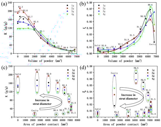
Figure 12.
Variation in amplification factor and structural damping ratio of different beams with powder volume and powder contact surface area: (a) The variation of amplification factor with the change of powder volume; (b) The variation of structural damping ratio with powder volume; (c) The variation of amplification factor with the change of powder contact surface area; (d) The variation of structural damping ratio with the change of powder contact surface area.
It is worth noting that, although the Cavity sample has the largest powder volume, its damping performance under 1 g and 2 g input is relatively poor compared to that of B0.6. This may be because the 0.6 mm strut diameter lattice reduces the powder volume by less than 7% (6750 → 6278.26 mm3), but increases the powder contact area with the inner wall by 128.7% (2250 → 5145.81 mm2). At this point, the interaction between the powder and the inner wall becomes the key factor contributing to the overall beam damping performance. However, as the strut diameter increases (0.6 → 1.8 mm), the powder volume of the self-sealing powder beams incorporating lattice structures decreases rapidly (6278.26 → 3532.83 mm3), while the contact area between the powder and the inner wall increases slowly (5145.81 → 7156.44 mm2). At this point, the increase in damping performance due to the interaction between the powder and the inner wall is smaller than the decrease in damping performance caused by the reduction in powder volume, resulting in an overall decrease in the damping performance of the self-sealing powder beams incorporating lattice structures. As the strut diameter increases further (1.8 → 3.3 mm), the powder volume decreases rapidly (3532.83 → 257.96 mm3), and the contact area between the powder and the inner wall also decreases simultaneously (7156.44 → 2580.3 mm2). The overall damping performance of the self-sealing powder beams incorporating lattice structures deteriorates significantly, with the amplification factor and structural damping ratio approaching those of the solid beam. In general, when designing self-sealing powder beams incorporating lattice structures, it is necessary to balance the powder volume and inner surface area to achieve better damping performance.
Figure 13 shows a comparison of the acceleration frequency response curves and peak acceleration values of different beams under a 1 g sweep input, obtained through finite element harmonic response analysis. For the Cavity and B0.6-B3.3 samples, the equivalent damping coefficients of the powders are 9.00, 20.00, 13.500, 7.800, 4.200, 2.400, 1.200, 0.200, 0.150, 0.125, and 0.040, respectively. As can be seen, the simulation and experimental results show only minor differences, indicating that the established dynamic model has high predictive accuracy. Since the equivalent damping of powder includes both the damping contributed by the interactions among the powder particles themselves and the interactions between the powder and the inner surface, the variation trends of the powder equivalent damping coefficient c, theoretical powder volume V, and theoretical inner surface area (area of powder contact) S for different samples are plotted, as shown in Figure 14. It can be noticed that compared to the Cavity sample, the B1.6 sample exhibits the highest powder equivalent damping coefficient due to its significantly increased powder contact surface area. As the lattice diameter further increases, the growth rate of the powder contact surface area slows down and begins to decrease when the strut diameter exceeds 1.8 mm. Concurrently, the continuous reduction in powder volume leads to diminished interactions between the powder and the inner wall, as well as within the powder itself, resulting in a progressive decline in the powder equivalent damping coefficient. Furthermore, a regression model for the equivalent damping coefficient of powder was established based on the theoretical powder volume V and the inner surface area (powder contact area) S, as shown in Equation (5). Through analysis of variance, the obtained regression model has an R-squared value of 95.98% (greater than 90%) and a p-value of 0.002 (less than 0.05), indicating that the model fits well and is statistically significant overall. Additionally, the p-values for V, S, V2, S2, and vs. are 0.691, 0.957, 0.688, 0.768, and 0.777, respectively, indicating that the significance of powder volume, inner surface area, and their interactions is similar, and their contributions to damping are comparable. In subsequent self-sealing powder beams incorporating lattice structure designs, this regression equation can be referenced to adjust the corresponding damping performance.
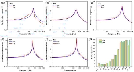
Figure 13.
Dynamic response simulation results: (a–e) Comparison of simulation and experimental acceleration frequency response curves for Cavity, B0.6, B1.5, B2.4, and B3.3 samples; (f) Comparison of simulation and experimental acceleration peak values for different samples.
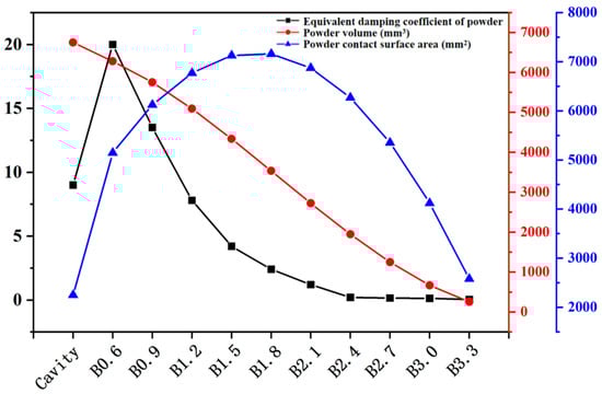
Figure 14.
Trends of the equivalent damping coefficient of powder, theoretical powder volume and theoretical powder contact surface area.
6. Conclusions
This study designed and fabricated self-sealing powder beams that incorporate lattice structures with different strut diameters using LPBF, and investigated their forming quality, stiffness, and damping performance. Additionally, a corresponding static model was established based on finite element analysis, revealing the mechanism by which the lattice influences the stiffness of the self-sealing powder beam. Furthermore, a corresponding dynamic model was established, revealing the interaction mechanism between the powder and the lattice. This study effectively demonstrates that the integrated design of the lattice and self-sealing powder can effectively regulate the stiffness and damping performance of LPBF beam structures. The specific research conclusions are as follows:
(1) LPBF can produce self-sealing powder beams that incorporate lattice structures with excellent manufacturing quality. The beams produced have no manufacturing defects such as pores or cracks, no broken or deformed struts in the lattice sections, and the cavities are filled with powder.
(2) The introduction of a lattice structure can effectively improve the bending stiffness of self-sealing powder beams. Compared with self-sealing powder beams with only cavities, incorporating a BCC lattice structure can achieve a bending stiffness improvement of more than 17%. In addition, when the lattice strut diameter is greater than 1.8 mm, the bending stiffness of the self-sealing powder beams incorporating lattice structures differs from that of the solid beam by less than 4%.
(3) The vibration response of the self-sealing powder beams incorporating lattice structures can be effectively controlled by changing the diameter of the lattice struts. When the strut diameter is 0.6 mm, due to the smaller powder volume loss and the greater increase in internal surface area, the damping performance is better. Compared with the self-sealing powder beam without a lattice structure, both the stiffness and damping performance are improved synergistically.
(4) When the strut diameter increases from 0.6 to 1.8 mm, the powder volume decreases rapidly, the inner surface area increases slowly, and the overall damping performance of the beams decreases. When the strut diameter increases from 1.8 to 3.3 mm, the powder volume decreases while the inner surface area also decreases, resulting in a significant reduction in the overall damping performance of the beams, with the amplification factor and structural damping ratio approaching those of a solid beam. When designing self-sealing powder beams incorporating lattice structures, it is necessary to balance the relationship between the powder volume and the inner surface area.
Author Contributions
Conceptualization, Y.X. and Z.X. (Zheng Xiang); methodology, J.T., T.Z. and M.S.; validation, Y.X. and Z.X. (Zheng Xiang); formal analysis, C.Z. and T.Z.; investigation, X.G. and M.S.; resources, Z.X. (Zhihui Xia), J.C. and S.H.; data curation, J.T. and X.G.; writing—original draft preparation, Y.X. and Z.X. (Zheng Xiang); writing—review and editing, J.C. and S.H.; visualization, C.Z.; supervision, Z.X. (Zhihui Xia); project administration, J.C. and S.H.; funding acquisition, J.C. and S.H. All authors have read and agreed to the published version of the manuscript.
Funding
This research was funded by the National Safety Academic Fund, grant number U2130201.
Data Availability Statement
The original contributions presented in this study are included in the article. Further inquiries can be directed to the corresponding authors.
Conflicts of Interest
The authors declare no conflicts of interest.
References
- Mottershead, J.E.; Ram, Y.M. Inverse eigenvalue problems in vibration absorption: Passive modification and active control. Mech. Syst. Signal Process. 2006, 20, 5–44. [Google Scholar] [CrossRef]
- Bosia, F.; Dal Poggetto, V.F.; Gliozzi, A.S.; Greco, G.; Lott, M.; Miniaci, M.; Ongaro, F.; Onorato, M.; Seyyedizadeh, S.F.; Tortello, M.; et al. Optimized structures for vibration attenuation and sound control in nature: A review. Matter 2022, 5, 3311–3340. [Google Scholar] [CrossRef]
- Xing, W.; Tuo, W.; Li, X.; Wang, T.; Yang, C. Micro-vibration suppression and compensation techniques for in-orbit satellite: A review. Chin. J. Aeronaut. 2024, 37, 1–19. [Google Scholar] [CrossRef]
- Chapain, S.; Aly, A. Vibration attenuation in high-rise buildings to achieve system-level performance under multiple hazards. Eng. Struct. 2019, 197, 109352. [Google Scholar] [CrossRef]
- Friend, R.D.; Kinra, V.K. Particle Impact Damping. J. Sound Vib. 2000, 233, 93–118. [Google Scholar] [CrossRef]
- Gagnon, L.; Morandini, M.; Ghiringhelli, G.L. A review of particle damping modeling and testing. J. Sound Vib. 2019, 459, 114865. [Google Scholar] [CrossRef]
- Xu, Z.; Wang, M.Y.; Chen, T. Particle damping for passive vibration suppression: Numerical modelling and experimental investigation. J. Sound Vib. 2005, 279, 1097–1120. [Google Scholar] [CrossRef]
- Xiao, W.; Li, J.; Pan, T.; Zhang, X.; Huang, Y. Investigation into the influence of particles’ friction coefficient on vibration suppression in gear transmission. Mech. Mach. Theory 2017, 108, 217–230. [Google Scholar] [CrossRef]
- Xiao, W.; Xu, Z.; Bian, H.; Li, Z. Lightweight heavy-duty CNC horizontal lathe based on particle damping materials. Mech. Syst. Signal Process. 2021, 147, 107127. [Google Scholar] [CrossRef]
- Zhang, K.; Xi, Y.; Chen, T.; Ma, Z. Experimental studies of tuned particle damper: Design and characterization. Mech. Syst. Signal Process. 2018, 99, 219–228. [Google Scholar] [CrossRef]
- Lu, Z.; Wang, Z.; Masri, S.F.; Lu, X. Particle impact dampers: Past, present, and future. Struct. Control Health Monit. 2018, 25, e2058. [Google Scholar] [CrossRef]
- Guo, H.; Ichikawa, K.; Sakai, H.; Zhang, H.; Zhang, X.; Tsuruta, K.; Makihara, K.; Takezawa, A. Numerical and experimental analysis of additively manufactured particle dampers at low frequencies. Powder Technol. 2022, 396, 696–709. [Google Scholar] [CrossRef]
- Guo, H.; Yoneoka, R.; Takezawa, A. Influence of cavity partition on the damping performance of additively manufactured particle dampers. Powder Technol. 2024, 439, 119675. [Google Scholar] [CrossRef]
- Harduf, Y.; Setter, E.; Feldman, M.; Bucher, I. Modeling additively-manufactured particle dampers as a 2DOF frictional system. Mech. Syst. Signal Process. 2023, 187, 109928. [Google Scholar] [CrossRef]
- Scott-Emuakpor, O.; Beck, J.; Runyon, B.; George, T. Determining unfused powder threshold for optimal inherent damping with additive manufacturing. Addit. Manuf. 2021, 38, 101739. [Google Scholar] [CrossRef]
- Ehlers, T.; Lachmayer, R. Design Rules for Laser Beam Melted Particle Dampers. Proc. Des. Soc. 2022, 2, 2443–2452. [Google Scholar] [CrossRef]
- Hollkamp, J.P.; Scott-Emuakpor, O.; Celli, D. Analyses of Damping Sustainability of Additively Manufactured Nickel Alloy Components Subjected to High Strain Loading Cycles. J. Eng. Gas Turbines Power 2023, 145, 031011. [Google Scholar] [CrossRef]
- Ehlers, T.; Tatzko, S.; Wallaschek, J.; Lachmayer, R. Design of particle dampers for additive manufacturing. Addit. Manuf. 2021, 38, 101752. [Google Scholar] [CrossRef]
- Ozcevik, B.; Soylemez, E.; Bediz, B.; Simsek, U. Effects of particle damper design parameters on the damping performance of laser powder bed fused structures. Int. J. Adv. Manuf. Technol. 2024, 130, 3917–3928. [Google Scholar] [CrossRef]
- Ashby, M.F. The properties of foams and lattices. Philos. Trans. R. Soc. A Math. Phys. Eng. Sci. 2005, 364, 15–30. [Google Scholar] [CrossRef]
- Maconachie, T.; Leary, M.; Lozanovski, B.; Zhang, X.; Qian, M.; Faruque, O.; Brandt, M. SLM lattice structures: Properties, performance, applications and challenges. Mater. Des. 2019, 183, 108137. [Google Scholar] [CrossRef]
- Chen, D.; Gao, K.; Yang, J.; Zhang, L. Functionally graded porous structures: Analyses, performances, and applications—A Review. Thin-Walled Struct. 2023, 191, 111046. [Google Scholar] [CrossRef]
- Miao, X.; Hu, J.; Xu, Y.; Su, J.; Jing, Y. Review on mechanical properties of metal lattice structures. Compos. Struct. 2024, 342, 118267. [Google Scholar] [CrossRef]
- Vogela, F.; Berger, S.; Özkaya, E.; Biermann, D. Vibration Suppression in Turning TiAl6V4 Using Additively ManufacturedTool Holders with Specially Structured, Particle Filled Hollow Elements. Procedia Manuf. 2019, 40, 32–37. [Google Scholar] [CrossRef]
- Werkle, K.T.; Menze, C.; Stehle, T.; Möhring, H.C. Additively manufactured, particle-filled damping structures withmagnetorheological fluids. Procedia CIRP 2021, 104, 1418–1423. [Google Scholar] [CrossRef]
- Corson, G.; Compton, B.; Gomez, M.; Schmitz, T. Internal feature design for increased damping by captured powder. In Proceedings of the ASPE 36th Annual Meeting, Minneapolis, MN, USA, 1–5 November 2021. [Google Scholar]
- Mohanraj, J.; Sahu, J. Numerical prediction of residual stress and distortion for laser powder bed fusion (LPBF) AM process of Ti-6Al-4V. Simul. Model. Pract. Theory 2025, 140, 103094. [Google Scholar] [CrossRef]
- Westbeld, J.; von Coburg, F.; Höfer, P. Forced-response characterization of PBF-LB/AlSi10Mg particle dampers with thin and flat cavities. Prog. Addit. Manuf. 2023, 8, 745–757. [Google Scholar] [CrossRef]
- Schmitz, T.; Gomez, M.; Ray, B.; Heikkenen, E.; Sisco, K.; Haines, M.; Osborne, J.S. Damping and mode shape modification for additively manufactured walls with captured powder. Precis. Eng. 2020, 66, 110–124. [Google Scholar] [CrossRef]
- Scott-Emuakpor, O.; Schoening, A.; Goldin, A.; Beck, J.; Runyon, B.; George, T. Internal Geometry Effects on Inherent Damping Performance of Additively Manufactured Components. AIAA J. 2021, 59, 379–385. [Google Scholar] [CrossRef]
- Rehmet, R.; Lorenz, S.; Hahn, V.; Lohrengel, A. Investigation on the Acoustical Transmission Path of Additively Printed Metals. Appl. Sci. 2022, 13, 180. [Google Scholar] [CrossRef]
- Ehlers, T.; Lachmayer, R. Design of Particle Dampers for Laser Powder Bed Fusion. Appl. Sci. 2022, 12, 2237. [Google Scholar] [CrossRef]


Disclaimer/Publisher’s Note: The statements, opinions and data contained in all publications are solely those of the individual author(s) and contributor(s) and not of MDPI and/or the editor(s). MDPI and/or the editor(s) disclaim responsibility for any injury to people or property resulting from any ideas, methods, instructions or products referred to in the content. |
© 2025 by the authors. Licensee MDPI, Basel, Switzerland. This article is an open access article distributed under the terms and conditions of the Creative Commons Attribution (CC BY) license.