Article

Point Defects in MoNbTi-Based Refractory Multi-Principal-Element Alloys

1
Materials Science and Engineering, School for Engineering of Matter, Transport & Energy, Arizona State University, Tempe, AZ 85287, USA
2
Institute of Radiation Physics, Helmholtz-Zentrum Dresden-Rossendorf, Bautzner Landstrasse 400, 01328 Dresden, Germany
3
Department of Nuclear Engineering, North Carolina State University, Raleigh, NC 27695, USA
4
Department of Physics, University of Trento, Via Sommarive 14, 38123 Povo, Trento, Italy
5
Department of Nuclear Engineering, University of Tennessee, Knoxville, 340 Zeanah Engineering Complex, Knoxville, TN 37996, USA
*
Author to whom correspondence should be addressed.
Metals 2025, 15(9), 989; https://doi.org/10.3390/met15090989 (registering DOI)
Submission received: 2 July 2025 / Revised: 19 August 2025 / Accepted: 28 August 2025 / Published: 6 September 2025

Abstract

As emergent material candidates for extreme environments, refractory high-entropy alloys (HEAs) or refractory multi-principal-element alloys (RMPEAs) comprising refractory metals feature qualities such as high radiation tolerance, corrosion resistance, and mechanical strength. A set of MoNbTi-based RMPEA samples with Al, Cr, V, and Zr additions are prepared by spark plasma sintering and investigated for their response to irradiation using 10 MeV Si+ ions with a dose of 1.43 × 10 15 ions/cm2. Positron annihilation spectroscopy and transmission electron microscopy are employed as atomic- and meso- scale techniques to reveal how chemical complexity, nanotwinning, and phase fractions play an important role in radiation-induced defect accumulation and damage tolerance. The study provides experimental evidence of nanotwinning acting as an effective sink for radiation-induced point defects.

1. Introduction

Refractory multi-principal-element alloys (RMPEAs) or high-entropy alloys (HEAs) continue to attract significant interest, owing to their remarkable durability in extreme environments [1,2,3,4]. Broadly speaking, several configurations of high-entropy alloys have shown favorable material response such as mechanical strength [5,6,7], thermal stability, radiation tolerance [8,9,10], and corrosion resistance [11]. Naturally, when these alloys are composed of refractory elements, RMPEAs are ideal material candidates for applications such as turbine components of aircraft propulsion systems, corrosive conditions during manufacturing processes, or highly radioactive environments such as plasma-facing components in a fusion reactor.
The selected elements (namely Mo, Nb, Ti, Al, Zr, and Cr) for this set of RMPEAs are based on their ability to form simple crystal phases such as body-centered cubic (BCC), hexagonal-closed packed (HCP), and face-centered cubic (FCC) structures [12,13]. During the design of these alloys, the goal is to maximize configurational entropy such that the alloys exhibit properties such as severe lattice distortion, sluggish diffusion, and cocktail effects [14]. Common strategies in the design of these alloys include using refractory materials for their high-temperature properties, exploring chemically complex mixtures to reduce defect mobility, and producing equiatomic solutions to maximize the entropy of mixing [15].
The MoNbTi family of RMPEAs has been extensively investigated for mechanical properties [16] and high-temperature resistance [17,18], however, there is little work in the literature on probing radiation-induced atomic-scale defects in RMPEAs, a regime where damage to the microstructure can also significantly alter the final state of the material. This work employs positron annihilation spectroscopy (PAS), which encompasses a set of well-known non-destructive techniques for probing atomic-scale vacancies at concentrations as low as 0.1 ppm. For a detailed review on PAS, see Selim 2019 [19]. The two methods utilized here to investigate atomic-scale defects are positron annihilation lifetime spectroscopy (PALS) and Doppler broadening spectroscopy (DBS). These techniques have been combined in previous works with other material characterization methods such as transmission electron microscopy (TEM) [20] and atomic probe tomography (APT) [21] to give insights on the fundamental mechanisms of radiation damage in Fe and FeCr. Although the body of work is limited, a growing number of studies performed using PAS on high-entropy alloys have been conducted [22,23,24,25]. In high-entropy configuration materials, early TEM studies have shown that increasing chemical disorder leads to a reduction in damage accumulation [26]. The current work applies PALS and DBS to investigate the effect of chemical disorder on early stages of radiation damage; it investigates a set of spark plasma sintering (SPS) samples based around a ternary composition (MoNbTi) alloyed with different ratios of Al, Cr, V, and Zr.
While several permutations of the additional elements V, Cr, Zr, and Al can be considered, the sets of alloys are chosen based on several factors such as SPS fabrication feasibility. Otherwise, many of these elements, individually or alloyed, are considered based on proven functionality in reactor environments. Therefore, it is worthwhile to test whether their performance in radiation extremes can be extended to RMPEAs. For instance, Zr is a well-known alloying element for cladding materials such as Zircaloy and ZIRLO. Vanadium alloys have shown resistance to void swelling [27]. Moreover, Al additions, particularly in Cantor alloys, have also demonstrated reduced volume swelling [28]. Several studies suggest that adding Al promotes structural stability and tolerance against radiation [29,30,31], by way of inducing BCC ordered phases. Finally, Cr is commonly found in structural steels and is especially resistant to oxidizing environments.
For convenience, the five samples in this work will be referred to throughout the paper as follows: MoNbTi (base), MoNbTiZr (base + Zr), AlMoNbTi (base + Al), CrMoNbTiV (base + CrV), and MoNbTiVZr (base + VZr). Microstructural analysis on the as-cast alloys using X-ray diffraction and TEM revealed that these alloys have varying fractions of single-phase BCC, dual-phase BCC, and BCC + Laves solid solutions [32]. Here we investigate how these phase structures and chemical disorder affect radiation-induced defects in these RMPEA systems and their radiation response. To help the reader with the interpretation of the positron data, the following section provides a brief introduction of defect analysis by PAS.
When implanted into a sample, positrons rapidly thermalize, diffuse, and annihilate in either a Bloch state or a defect state. At room temperature, single atom vacancies bind positrons within a potential well with a typical binding energy of ~1 eV, enough to keep positrons trapped until they annihilate. This positron trapping at defects leads to characteristic changes in the measured annihilation parameters using PALS and DBS. In PALS measurements, positrons have characteristic lifetimes based on factors such as elemental specificity [33] and atomic-scale defect structures [34]. The positron lifetime spectrum can be described by the sum of states i ,
N ( t ) = i = 1 k + 1 I i τ i exp ( t τ i )   ,
where τ i are the individual lifetime components deconvoluted from the spectrum with I i being their related intensities. Using non-linear fitting procedures, these individual lifetime components can be extracted and be used to identify defect size and types [34]. DBS parameters are obtained by quantifying the broadening of the e+–e annihilation gamma peak which is centered at 511 keV. The broadening of the 511 keV peak is dominated by the momentum distribution of the electrons in the lattice [35,36]. That is, since the positrons are thermal, the shift in energies from the annihilation gammas is largely dominated by the momentum distribution of the electrons. As a result, the width of the 511 keV peak can be compartmentalized into the so-called shape (S) and wing (W) parameters. The S parameter is associated with the annihilation of low-momentum valence electrons and is proportional to the defect content of the material system [37]. The W parameter is related to annihilation contributions from the high-momentum core electrons [38].

2. Experimental Methods

2.1. Sample Preparation and Irradiation

The samples were prepared by California Nanotechnologies using spark plasma sintering (SPS) with an SPS 7.40 MkIV unit [32]. To achieve a chemically homogenous mixture and maximize potential defect sinks, the high-purity powders were cryogenically milled to ensure grain sizes less than 1 μm. The elemental compositions of each RMPEA are provided in Table 1. For a comprehensive analysis describing density, chemical composition, lattice parameters, and fabrication of these RMPEAs using SPS, see Beausoleil et al. [32]. Samples were found to be heterogeneous with nanograined microstructures. They contain large grain sizes of about 1 μm, with smaller 200 nm grains in between. The addition of light elements such as Al decreases the overall density of the system, forming BCC + FCC phases and BCC + B2 two-phase structures [30].
Sample irradiation was conducted at the Ion Beam Laboratory at Sandia National Laboratoryusing a 3 MV tandem accelerator. Si ions were used to induce damage with a fluence of 1.43 × 10 15 ions/cm2 at 10 MeV to avoid introducing Si impurities into the lattice.

2.2. Microstructural Characterization

The fabricated specimens were mechanically polished and lift-out samples were prepared using a focused-ion beam (FIB) with an FEI Quanta 3D FEG Dual Beam scanning electron microscope (SEM) (Thermofisher Scientific, Waltham, MA, USA). Characterization was performed with an FEI Talos 200X transmission electron microscope (TEM) (Thermofisher Scientific, Waltham, MA, USA) to obtain high-angle annular dark-field (HAADF) images, selected area electron diffraction (SAED) patterns, and chemical analysis through scanning transmission electron microscopy (STEM) (Thermofisher Scientific, Waltham, MA, USA) energy dispersive spectrometry (EDS).

2.3. PAS Measurements

Variable-energy PALS measurements were performed at the Helmholtz-Zentrum Dresden-Rossendorf (HZDR) laboratory, using the Electron LINAC with high Brilliance and low Emittance (EBLE) facility in Dresden, Germany [39,40]. The measurements were carried out at the end station of the mono-energetic positron source (MePS). Incident positron energies were from 0.5–12 keV. Variable-energy DBS measurements were performed at the HZDR’s SPONSOR beamline [41,42]. Positron implantation energies ranged from 0.5–35 keV for depth profiling measurements up to ~1.6 μm, subject to material densities. For DBS, high-purity germanium (HPGe) detectors were used to record the energy of the annihilation photons with energy resolution of 1.09 keV.

3. Results and Discussion

3.1. Microstructural and Phase Analysis

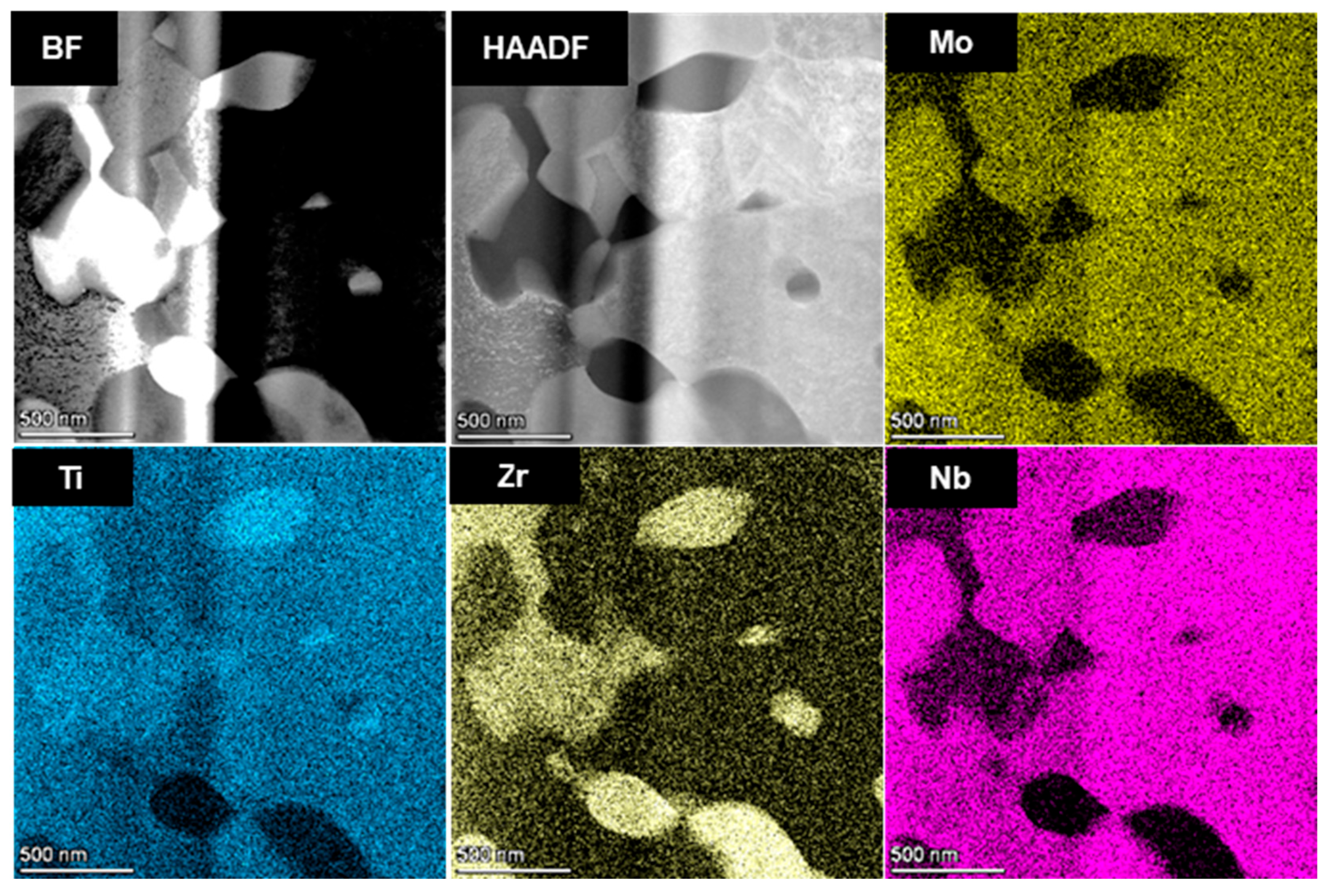
Figure 1a represents the bright field (BF) and HAADF micrographs and elemental distribution maps of MoNbTi alloy. The alloy showed a bimodal grain size distribution (micro- and nanorange) as might be the case for many alloy systems processed through non-equilibrium processing techniques like powder metallurgy followed by SPS. The three base elements (i.e., Mo, Nb, and Ti) mix homogenously throughout the matrix as shown in Figure 1 except for a few grains that are rich in Ti, which is attributed to its contrasting crystal structure from that of Mo and Nb. Figure 1b shows the selected area electron diffraction (SAED) analysis from the matrix phase which confirms its BCC structure along the [ 3   3 ¯   1 ] zone axis (ZA) with lattice parameter of a = 3.22 Å. Figure 1c depicts the SAD analysis from the Ti-rich phase confirming its HCP structure with lattice parameters of a = 2.95 Å; c = 4.69 Å along the [ 1 ¯   1   0 ] ZA.
With the existence of Zr in MoNbTiZr alloy (Figure 2), Ti tends to mix into the solid solution with Mo and Nb, while Zr segregates on its own which may be due to the fact that Zr is the element with highest atomic radius to be adopted into the BCC unit cell. However, the preference of Ti to sometimes segregate along with Zr is also observed in Figure 2.
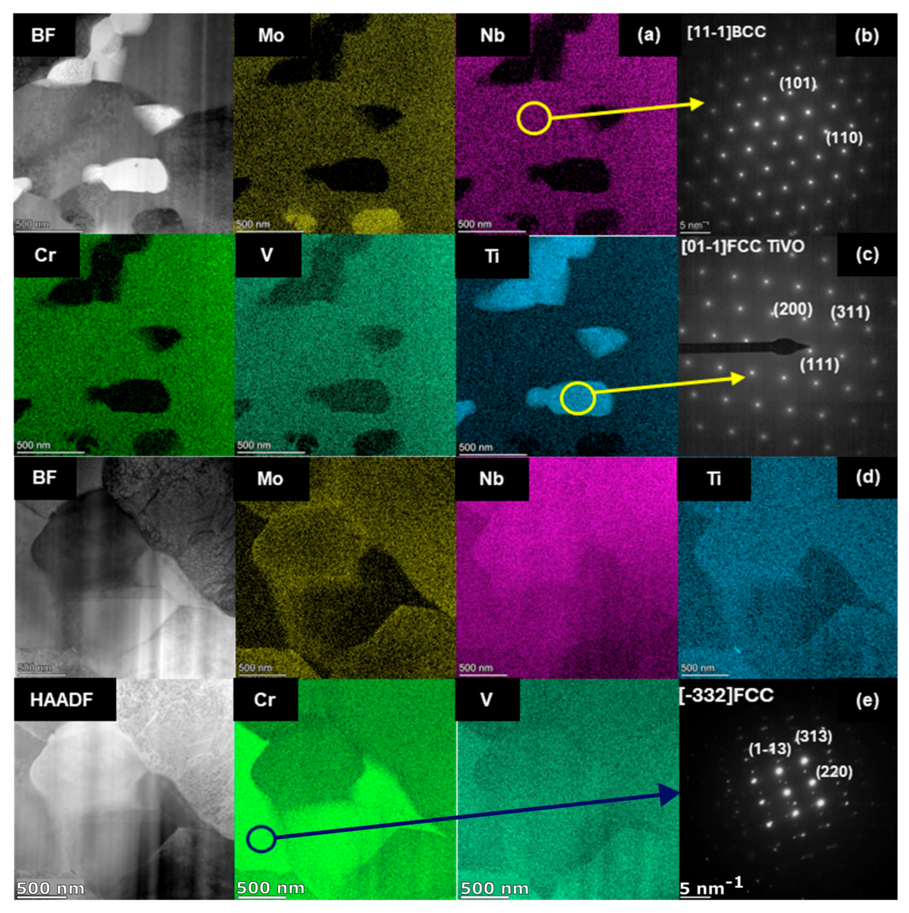
MoNbTiCrV alloy resulted in a comparatively simpler microstructure with a near homogeneous matrix along with the presence of Cr (Nb, V) and Ti (V)-rich phases as can be observed in Figure 3a,d. The respective SAED analyses of these phases have been presented in Figure 3b,c,e which confirm the crystal structure of these phases to be BCC, Ti0.92V0.08O type FCC oxide, and Cr1.7V0.3Nb type C15 Laves phase (FCC).
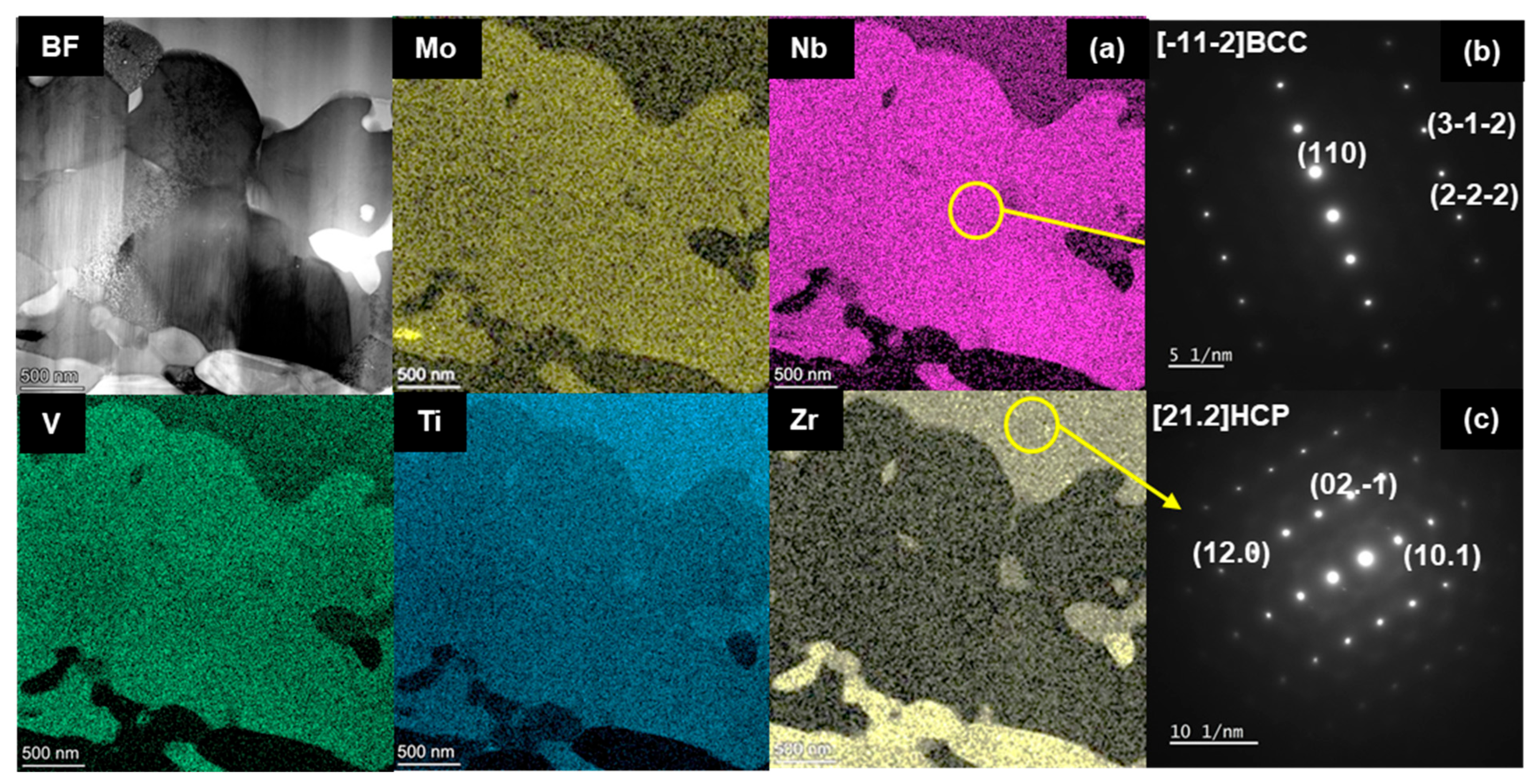
Figure 4 shows the elemental distribution maps of (base + VZr) alloy which shows segregation of (Mo, Nb, V) in the matrix and (Ti, Zr) towards the second phase. The respective SAED analyses of these phases in (b, c) confirm their crystal structures of BCC and HCP, respectively.

3.2. Defect and PALS Analysis

In this work, PALS and DBS measured as a function of implantation energy and depth. The mean positron implantation depth z is dependent on several physical factors and is calculated as follows:
z = A ρ E p n
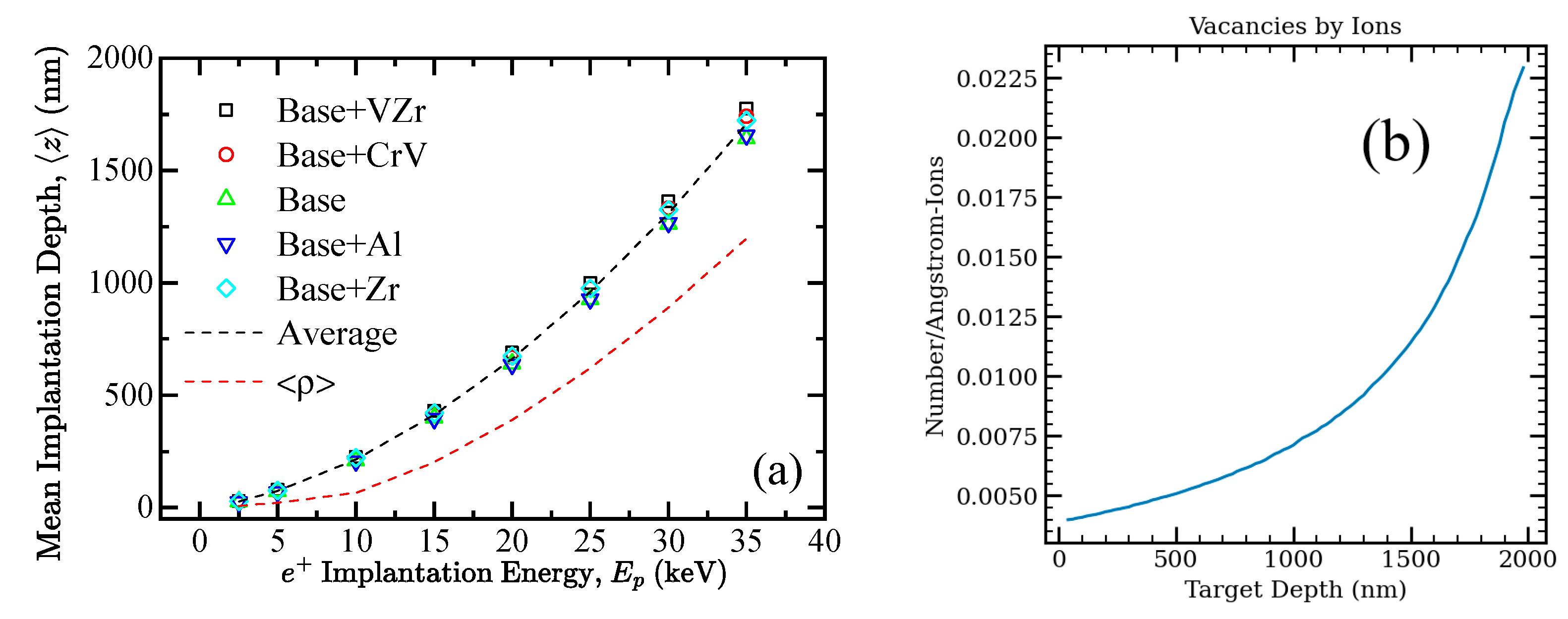
E p is the beam energy, ρ is the material density, and A and n are empirically determined material dependent parameters. The positron implantation depths are calculated by averaging z across all RMPEAs based on the model developed by Ghosh et al. [43]. The density-averaged implantation depth as shown in Figure 5 is utilized in subsequent analyses.
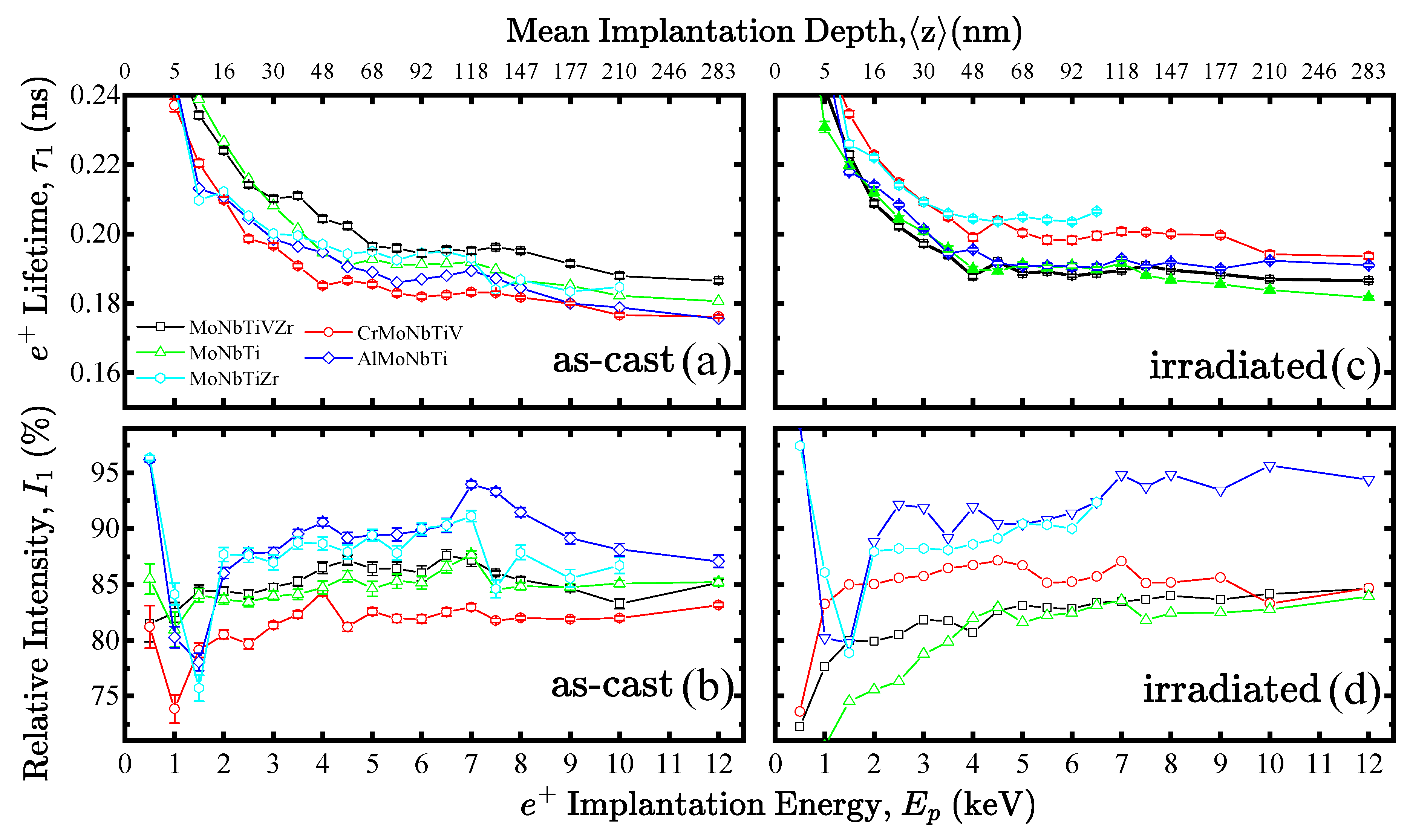
Since there are no computational or theoretical bulk lifetimes calculated for these RMPEAs, estimates of the bulk lifetimes are calculated as the average lifetimes weighted by the constituent elements of each RMPEA system. The experimentally determined values for bulk and monovacancy states for the pure elements are provided in Table 2, along with the calculated lifetime estimates of the RMPEAs. In Figure 6, depth-resolved PALS measurements using a monoenergetic pulsed beam at implantation energies up to 12 keV provide the first lifetime component for both as-cast and irradiated samples and are plotted as a function of implantation energy and implantation depth.
The shortest-lived lifetime component, τ 1 , measured for each of the RMPEAs is significantly longer than τ b , a v g , the estimated lifetime for annihilation in the bulk (defect-free region). This indicates that all positrons annihilate from defect states [34]. The first lifetime component τ 1 may be a mix of two components from annihilations in monovacancy and dislocations [24] that cannot be resolved.

3.3. DBS Analysis

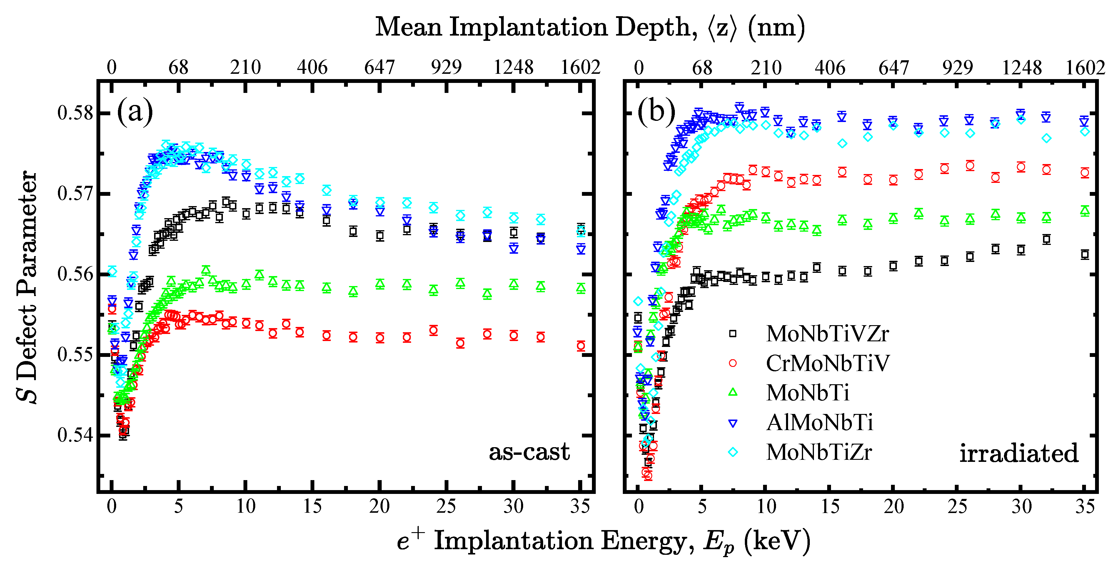
Figure 7 shows the S(E) defect parameters for the RMPEA systems in the as-cast and irradiated samples along with the mean penetration depth, z . Sharp increases in the magnitude of S(E) within the range 5–50 nm can be attributed to the transition between the interface of an oxide layer and the sample surface. Moreover, surface interactions for backscattered positrons and their diffusion back to the surface of the material at lower energies can also explain the sharp changes in S parameters from 3 5   keV .

3.4. Characteristics of Defects in As-Cast Samples

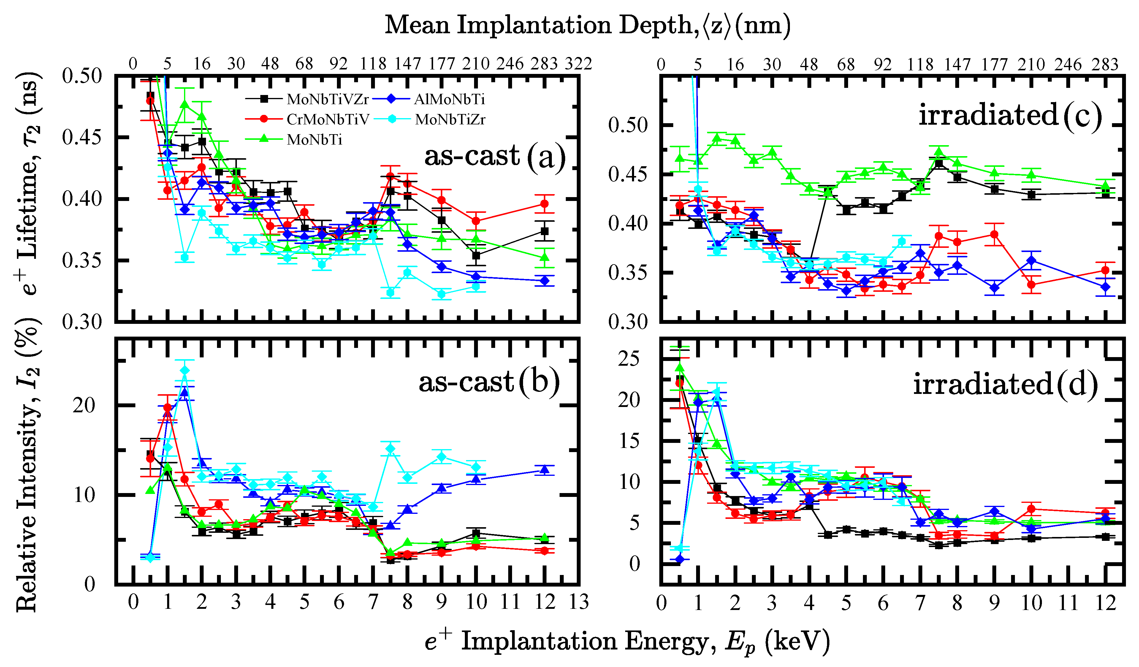
Figure 8a shows τ 2 lifetime components for as-cast samples which correspond to monovacancies and small vacancy clusters. There are two distinct groups in terms of monovacancy content, namely: base + CrV and base + VZr with τ 2 values of about 200 ps. Meanwhile, the base + Al and base + Zr systems exhibit much longer τ 2 lifetimes, at ~400 ps, indicating the presence of larger vacancy clusters. Overall, vacancy content appears to trend with HCP-rich phases, in order of increasing HCP fractions.
S(E) profiles show significantly different defect characteristics across all RMPEAs with changes in chemical complexity. Before irradiation, the RMPEA systems show a large concentration of defects near the surface which is reflected by the peaks in the S(E) profiles near the surface, at mean depths of around 7–68 nm. Before irradiation, the S defect parameter generally decreases as a function of depth since positrons probe through a thin oxide layer around 20–50 nm thick, a high defect content sub-surface around 50–170 nm, and eventually approach the values measured in the bulk of the sample (>170 nm). Although oxidation and corrosion are not the focus of this study, it should be mentioned that the RMPEAs with Al and Zr additions likely have a monolayer of oxidation which is consistent with the higher S values on the surface [44]. Structural characterization of these RMPEAs presented above revealed multi-phase compositions of BCC1, BCC2, and intermetallic C15 Laves. It can be seen from Figure 7 that S parameters are lower for alloys that mostly comprise BCC elements, the lowest being base + CrV, containing a BCC1 phase fraction of 90%. The RMPEAs with larger S(E) profiles indicate a greater presence of open volume defects in systems with increasing HCP or FCC phase fractions, in this case base + Al and base + Zr. The two highest BCC1 phase fractions are the base alloy and base + CrV.
S-W analysis of valence and core annihilation parameters of the alloys are shown in Figure 9 and Figure 10, and the labels on the figures show how defect structure changes with increasing depth, indicated by the direction of the arrow in the first plot (base + VZr and base + CrV). The base + VZr and base + Al alloys have much larger W defect parameters than the other RMPEAs. It should be noted the extended ranges of W parameters are largely attributable to the surface region. This effect can be described by an oxidation and corrosion layer that has formed on the surface of the base + VZr and base + Al alloys [45].
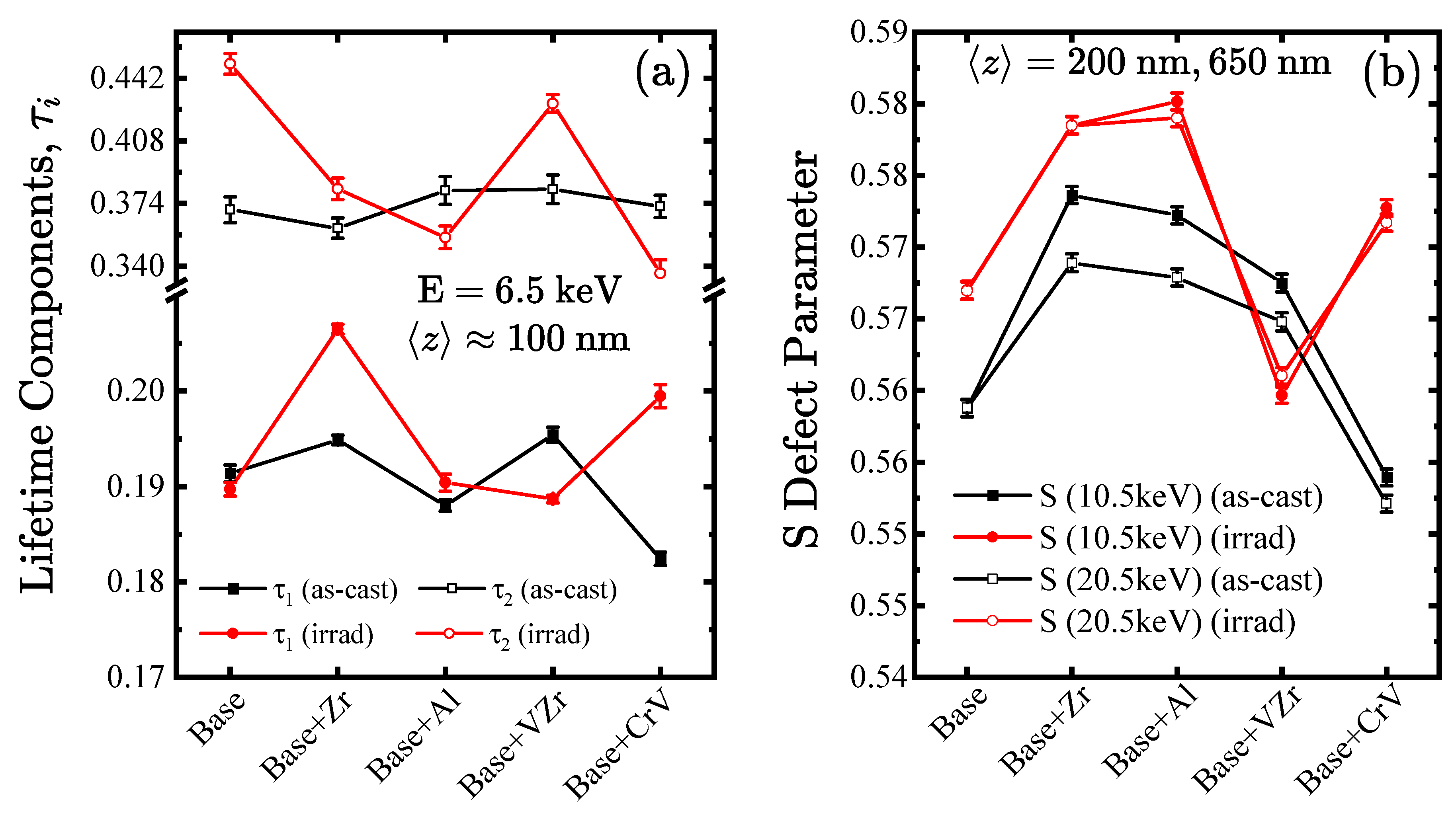
Both base + VZr and base + CrV systems show significant differences between their S-W surface states with W / W b u l k parameters that are proportional to higher Z elements. In this case, Z = 24 for Cr and Z = 40 for Zr. Apart from base + Al, all other RMPEAs do not exhibit a significant change in defect structure as other alloying elements are added. Many of these RMPEAs already begin with a high defect content as indicated by saturation of positron trapping revealed from PALS measurements. Positron parameters sampled at 100, 200, and 650 nm are plotted in Figure 10 across the five samples to show how they vary due to chemical composition. At a positron implantation energy of around 10   keV , the mean depth corresponds to ~ 200   nm for each alloy.

3.5. Characterization of Defects in Irradiated Samples

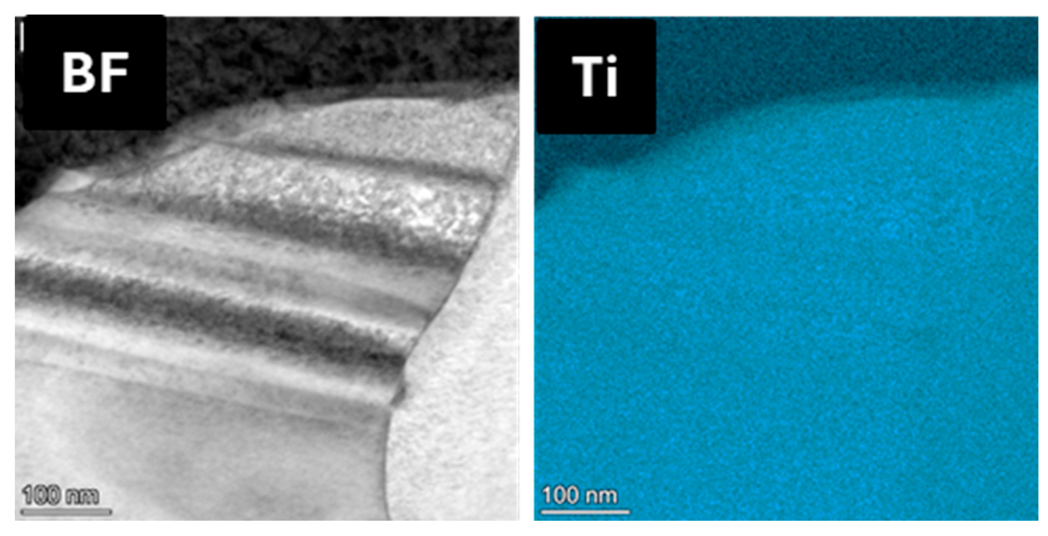
As expected, the ion-induced radiation damage significantly alters the microstructure of the RMPEAs, which is reflected in the large differences between the as-cast and irradiated RMPEAs across several positron parameters. The irradiated S(E) profiles show a significant increase in defect content in most samples with some exceptions. The TEM analysis revealed that the pristine base sample has a large BCC1 phase along with nanotwinning effects with Ti HCP grains (Figure 11) that were not present in the more complex alloys. An atomic simulation study performed on Ti grains by K. Siemek showed that these nanotwinned structures are integral to radiation tolerance with evidence of self-healing properties [46]. The irradiated base MoNbTi exhibits consistent S values throughout the depth suggesting that the defects are homogenously distributed throughout the layers. This alloy after irradiation exhibits relatively low S values indicating low defect contents, accompanied by an increase in the defect lifetime component τ 2 without an increase in its intensity. This implies an increase in the size of the original vacancy clusters without inducing new vacancy clusters after irradiation. This interpretation is due to the presence of nanotwins which may facilitate recombination of interstitials and vacancies. This result provides experimental evidence on how nanotwins may change the formation and evolution of radiation-induced defects.
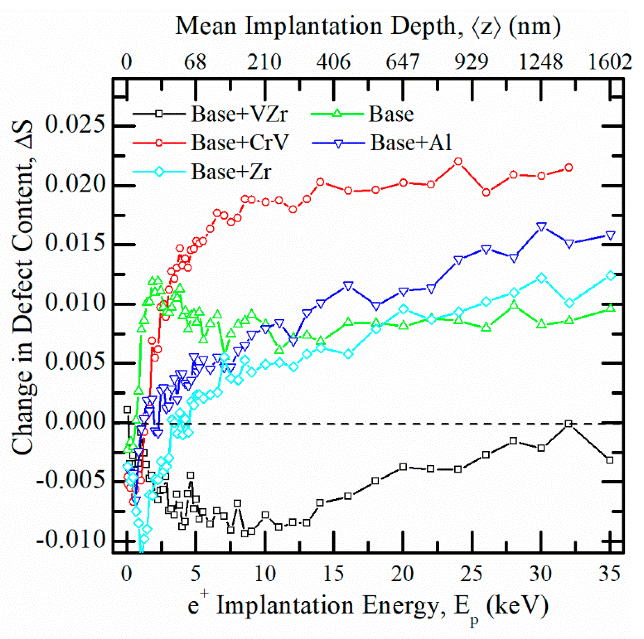
Another way to visualize the radiation response of the RMPEAs is by plotting the difference in S parameters, Δ S , between the as-cast and irradiated samples as shown in Figure 12. The Δ S values are expected to be positive since irradiation generally increases the defect content in a material, whereas negative ΔS trends may indicate a decrease in the original defect content, which is seen at all depths in the case of the base + VZr alloy. As mentioned earlier, the MoNbTi alloy shows relatively low defect contents after irradiation, meanwhile, the base + Zr additions also show a similar behavior. In the VZr system, at all implantation energies, the lifetime components and S parameters for the as-cast MoNbTiVZr system remain consistently higher than those of the irradiated samples.
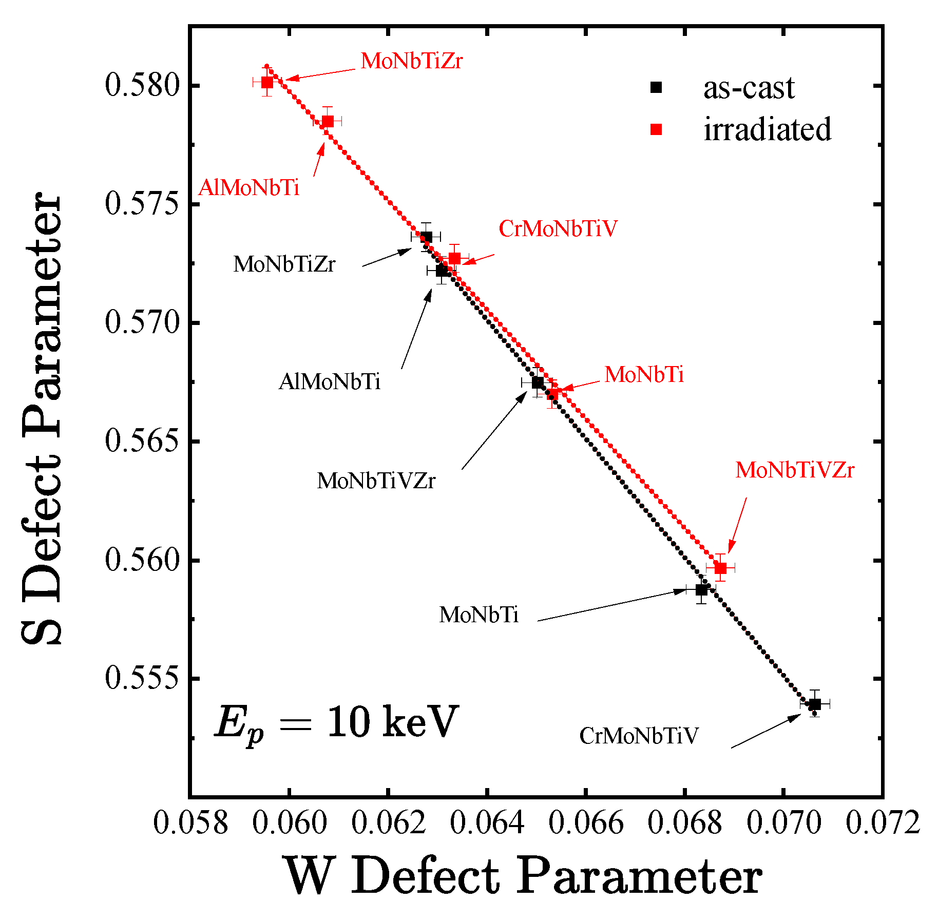
Defect shrinking in MoNbTiVZr can also be seen in Figure 6, Figure 7, and Figure 10 where both the first lifetime component and S defect parameters show lower values in the irradiated RMPEA. However, the case is not the same for the second lifetime component of the MoNbTiVZr system. This suggests that smaller vacancy clusters are being recombined into larger defects but also reduces the overall defect content in the system. Another instance of shrinking of defect size is in AlMoNbTi, where Figure 10 show regions of lower τ2 values after the sample is irradiated. Moreover, the S-W analysis of the VZr alloy in Figure 13 shows that the point after irradiation deviates slightly from the fitted line of the as-cast sample, signaling some change in the defect structure after irradiation at the positron implantation depth of 10 keV. This behavior combined with the decrease in S value indicates that the original defects in the sample may act as sinks for radiation-induced defects. Finally, Figure 7 shows that the VZr system which has the most HCP phase (about 40%) exhibits S values meaning larger defect content in the as-cast samples. These original defects seem to act as defect sinks for radiation-induced defects.

4. Conclusions

Defect studies by PAS were performed on samples of MoNbTi-based multi-principal-element alloys fabricated by spark plasma sintering. Using PALS and DBS measurements, we observe how chemical complexity alters the microstructure of these alloys before and after irradiation. Measurements performed on as-cast samples show a high level of defect content attributed to severe lattice distortion and multi-phases created during the SPS fabrication process. Al and Zr additions to the base alloy led to the formation of an oxide layer on the sample surface. As expected, all RMPEAs show changes following irradiation. However, the RMPEAs fabricated with microstructures that include Zr additions or nanotwinning (namely, the base, base + Zr, and base + VZr alloys) show evidence of radiation resistance. The mechanisms behind the higher radiation resistance have been explained as follows. In the case of Zr alloys, the addition of Zr led to the formation of HCP phase and a high level of vacancy clusters in the as-cast samples which act as sinks for both interstitials and vacancies. This is evident by the increase in the size of the vacancy clusters and the decrease in their numbers after irradiation. For the samples with nanotwins, the mechanism behind radiation resistance is explained by the role of nanotwins to act as recombination centers for interstitials and vacancies during collision cascades.

Author Contributions

Conceptualization, D.K. and F.A.S.; methodology, T.h.C., M.O.L., S.A., M.B., R.C.F., A.C.L.J., A.W., D.K., F.A.S., and K.H.; validation, T.h.C., M.O.L., S.A., M.B., R.C.F., A.C.L.J., A.W., D.K., F.A.S., and K.H.; formal analysis, T.h.C. and M.O.L.; investigation, T.h.C., M.O.L., S.A., M.B., R.C.F., A.C.L.J., and K.H.; resources, A.W., D.K., F.A.S., and K.H.; data curation, T.h.C., M.O.L., and S.A.; writing—original draft preparation, T.h.C. and S.A.; writing—review and editing, F.A.S.; visualization, M.O.L., S.A., M.B., and K.H.; supervision, A.W., D.K., and F.A.S.; project administration, F.A.S.; funding acquisition, F.A.S. All authors have read and agreed to the published version of the manuscript.

Funding

This research was funded by the National Science Foundation (NSF), grant number DMR-2425965. Part of this work was supported as part of FUTURE, an Energy Frontier Research Center funded by the U.S. Department of Energy, Office of Science, Basic Energy Sciences. This work was also performed, in part, at the Center for Integrated Nanotechnologies, an Office of Science User Facility operated for the U.S. Department of Energy (DOE) Office of Science by Los Alamos National Laboratory (Contract 89233218CNA000001) and Sandia National Laboratories (Contract DE-NA-0003525).

Data Availability Statement

The original contributions presented in this study are included in the article. Further inquiries can be directed to the corresponding author.

Acknowledgments

Parts of this research were carried out at ELBE at the Helmholtz-Zentrum Dresden-Rossendorf e.V., a member of the Helmholtz Association. We would like to thank the facility staff for assistance.

Conflicts of Interest

The authors declare no conflicts of interest. The funders had no role in the design of the study; in the collection, analyses, or interpretation of data; in the writing of the manuscript; or in the decision to publish the results.

References

  1. Yeh, J.-W.; Chen, S.-K.; Lin, S.-J.; Gan, J.-Y.; Chin, T.-S.; Shun, T.-T.; Tsau, C.-H.; Chang, S.-Y. Nanostructured High-Entropy Alloys with Multiple Principal Elements: Novel Alloy Design Concepts and Outcomes. Adv. Eng. Mater. 2004, 6, 299–303. [Google Scholar] [CrossRef]
  2. Liu, L.; Zhang, Y.; Han, J.; Wang, X.; Jiang, W.; Liu, C.-T.; Zhang, Z.; Liaw, P.K. Nanoprecipitate-Strengthened High-Entropy Alloys. Adv. Sci. 2021, 8, 2100870. [Google Scholar] [CrossRef]
  3. Cantor, B.; Chang, I.T.H.; Knight, P.; Vincent, A.J.B. Microstructural Development in Equiatomic Multicomponent Alloys. Mater. Sci. Eng. A 2004, 375–377, 213–218. [Google Scholar] [CrossRef]
  4. Zhang, Y.; Yang, X.; Liaw, P.K. Alloy Design and Properties Optimization of High-Entropy Alloys. JOM 2012, 64, 830–838. [Google Scholar] [CrossRef]
  5. Yang, T.; Zhao, Y.; Liu, W.; Kai, J.; Liu, C. L12-Strengthened High-Entropy Alloys for Advanced Structural Applications. J. Mater. Res. 2018, 33, 2983–2997. [Google Scholar] [CrossRef]
  6. Tong, C.-J.; Chen, M.-R.; Yeh, J.-W.; Lin, S.-J.; Lee, P.-H.; Shun, T.-T.; Chang, S.-Y. Mechanical Performance of the AlXCoCrCuFeNi High-Entropy Alloy System with Multiprincipal Elements. Metall. Mater. Trans. A 2005, 36, 1263–1271. [Google Scholar] [CrossRef]
  7. Iroc, L.K.; Tukac, O.U.; Tanrisevdi, B.B.; El-Atwani, O.; Tunes, M.A.; Kalay, Y.E.; Aydogan, E. Design of Oxygen-Doped TiZrHfNbTa Refractory High Entropy Alloys with Enhanced Strength and Ductility. Mater. Des. 2022, 223, 111239. [Google Scholar] [CrossRef]
  8. Kumar, N.A.P.K.; Li, C.; Leonard, K.J.; Bei, H.; Zinkle, S.J. Microstructural Stability and Mechanical Behavior of FeNiMnCr High Entropy Alloy under Ion Irradiation. Acta Mater. 2016, 113, 230–244. [Google Scholar] [CrossRef]
  9. El Atwani, O.; Vo, H.T.; Tunes, M.A.; Lee, C.; Alvarado, A.; Krienke, N.; Poplawsky, J.D.; Kohnert, A.A.; Gigax, J.; Chen, W.-Y.; et al. A Quinary WTaCrVHf Nanocrystalline Refractory High-Entropy Alloy Withholding Extreme Irradiation Environments. Nat. Commun. 2023, 14, 2516. [Google Scholar] [CrossRef] [PubMed]
  10. Li, T.-X.; Miao, J.-W.; Guo, E.-Y.; Huang, H.; Wang, J.; Lu, Y.-P.; Wang, T.-M.; Cao, Z.-Q.; Li, T.-J. Tungsten-Containing High-Entropy Alloys: A Focused Review of Manufacturing Routes, Phase Selection, Mechanical Properties, and Irradiation Resistance Properties. Tungsten 2021, 3, 181–196. [Google Scholar] [CrossRef]
  11. Egami, T.; Guo, W.; Rack, P.D.; Nagase, T. Irradiation Resistance of Multicomponent Alloys. Metall. Mater. Trans. A 2014, 45, 180–183. [Google Scholar] [CrossRef]
  12. Tsai, M.-H. Three Strategies for the Design of Advanced High-Entropy Alloys. Entropy 2016, 18, 252. [Google Scholar] [CrossRef]
  13. Senkov, O.N.; Wilks, G.B.; Miracle, D.B.; Chuang, C.P.; Liaw, P.K. Refractory High-Entropy Alloys. Intermetallics 2010, 18, 1758–1765. [Google Scholar] [CrossRef]
  14. Miracle, D.B.; Senkov, O.N. A Critical Review of High Entropy Alloys and Related Concepts. Acta Mater. 2017, 122, 448–511. [Google Scholar] [CrossRef]
  15. Zhang, Y.; Zhou, Y.J.; Lin, J.P.; Chen, G.L.; Liaw, P.K. Solid-Solution Phase Formation Rules for Multi-Component Alloys. Adv. Eng. Mater. 2008, 10, 534–538. [Google Scholar] [CrossRef]
  16. Senkov, O.N.; Wilks, G.B.; Scott, J.M.; Miracle, D.B. Mechanical Properties of Nb25Mo25Ta25W25 and V20Nb20Mo20Ta20W20 Refractory High Entropy Alloys. Intermetallics 2011, 19, 698–706. [Google Scholar] [CrossRef]
  17. Senkov, O.N.; Miracle, D.B.; Chaput, K.J.; Couzinie, J.-P. Development and Exploration of Refractory High Entropy Alloys—A Review. J. Mater. Res. 2018, 33, 3092–3128. [Google Scholar] [CrossRef]
  18. Lee, C.; Xie, D.; Kyle Derby, B.; Kevin Baldwin, J.; Tandoc, C.; EI Atwani, O.; Hu, Y.-J.; Valdez, J.A.; Li, N.; Fensin, S.J. An Experimentally Driven High-Throughput Approach to Design Refractory High-Entropy Alloys. Mater. Des. 2022, 223, 111259. [Google Scholar] [CrossRef]
  19. Selim, F.A. Positron Annihilation Spectroscopy of Defects in Nuclear and Irradiated Materials—A Review. Mater. Charact. 2021, 174, 110952. [Google Scholar] [CrossRef]
  20. Kim, H.; Chancey, M.R.; Chung, T.; Brackenbury, I.; Liedke, M.O.; Butterling, M.; Hirschmann, E.; Wagner, A.; Baldwin, J.K.; Derby, B.K.; et al. Interface Effect of Fe and Fe2O3 on the Distributions of Ion Induced Defects. J. Appl. Phys. 2022, 132, 105901. [Google Scholar] [CrossRef]
  21. Agarwal, S.; Butterling, M.; Liedke, M.O.; Yano, K.H.; Schreiber, D.K.; Jones, A.C.L.; Uberuaga, B.P.; Wang, Y.Q.; Chancey, M.; Kim, H.; et al. The Mechanism behind the High Radiation Tolerance of Fe–Cr Alloys. J. Appl. Phys. 2022, 131, 125903. [Google Scholar] [CrossRef]
  22. Elsayed, M.; Krause-Rehberg, R.; Eisenschmidt, C.; Eißmann, N.; Kieback, B. Defect Study in CoCrFeMnNi High Entropy Alloy by Positron Annihilation Lifetime Spectroscopy. Phys. Status Solidi A 2018, 215, 1800036. [Google Scholar] [CrossRef]
  23. Xu, Q.; Zhu, T.; Zhong, Z.H.; Cao, X.Z.; Tsuchida, H. Investigation of Irradiation Resistance Characteristics of Precipitation Strengthened High-Entropy Alloy (CoCrFeNi)95Ti1Nb1Al3 Using Slow Positron Beam. J. Alloys Compd. 2021, 888, 161518. [Google Scholar] [CrossRef]
  24. Čížek, J.; Vlasák, T.; Melikhova, O. Characterization of Lattice Defects in Refractory Metal High-Entropy Alloy HfNbTaTiZr by Means of Positron Annihilation Spectroscopy. Phys. Status Solidi A 2022, 219, 2100840. [Google Scholar] [CrossRef]
  25. Tuomisto, F.; Makkonen, I.; Heikinheimo, J.; Granberg, F.; Djurabekova, F.; Nordlund, K.; Velisa, G.; Bei, H.; Xue, H.; Weber, W.J.; et al. Segregation of Ni at Early Stages of Radiation Damage in NiCoFeCr Solid Solution Alloys. Acta Mater. 2020, 196, 44–51. [Google Scholar] [CrossRef]
  26. Zhang, Y.; Stocks, G.M.; Jin, K.; Lu, C.; Bei, H.; Sales, B.C.; Wang, L.; Béland, L.K.; Stoller, R.E.; Samolyuk, G.D.; et al. Influence of Chemical Disorder on Energy Dissipation and Defect Evolution in Concentrated Solid Solution Alloys. Nat. Commun. 2015, 6, 8736. [Google Scholar] [CrossRef]
  27. Lwai, T.; Sekimura, N.; Garner, F.A. Void Swelling Behavior in Ion-Irradiated Vanadium Alloys. J. Nucl. Mater. 1996, 239, 157–161. [Google Scholar] [CrossRef]
  28. Zhang, Z.; Armstrong, D.E.J.; Grant, P.S. The Effects of Irradiation on CrMnFeCoNi High-Entropy Alloy and Its Derivatives. Prog. Mater. Sci. 2022, 123, 100807. [Google Scholar] [CrossRef]
  29. Xia, S.Q.; Yang, X.; Yang, T.F.; Liu, S.; Zhang, Y. Irradiation Resistance in AlxCoCrFeNi High Entropy Alloys. JOM 2015, 67, 2340–2344. [Google Scholar] [CrossRef]
  30. Ayyappan, S.; Forrester, J.S.; Selim, F.; Beausoleil, G.; Kaoumi, D. Effect of Al Addition to the Multi-Principal Elemental AlxCrFeNiCu Alloy System in Terms of the Resulting Microstructure and Ion Irradiation Response. J. Alloys Compd. 2025, 1031, 180882. [Google Scholar] [CrossRef]
  31. Senkov, O.N.; Woodward, C.; Miracle, D.B. Microstructure and Properties of Aluminum-Containing Refractory High-Entropy Alloys. JOM 2014, 66, 2030–2042. [Google Scholar] [CrossRef]
  32. Beausoleil, G.L.; Parry, M.E.; Mondal, K.; Kwon, S.; Gomez-Hurtado, L.R.; Kaoumi, D.; Aguiar, J.A. Spark Plasma Sintered, MoNbTi-Based Multi-Principal Element Alloys with Cr, V, and Zr. J. Alloys Compd. 2022, 927, 167083. [Google Scholar] [CrossRef]
  33. Robles, J.M.C.; Ogando, E.; Plazaola, F. Positron Lifetime Calculation for the Elements of the Periodic Table. J. Phys. Condens. Matter 2007, 19, 176222. [Google Scholar] [CrossRef]
  34. Schultz, P.J.; Lynn, K.G. Interaction of Positron Beams with Surfaces, Thin Films, and Interfaces. Rev. Mod. Phys. 1988, 60, 701–779. [Google Scholar] [CrossRef]
  35. Selim, F.A.; Wells, D.P.; Harmon, J.F.; Kwofie, J.; Erikson, G.; Roney, T. New Positron Annihilation Spectroscopy Techniques for Thick Materials. Radiat. Phys. Chem. 2003, 68, 427–430. [Google Scholar] [CrossRef]
  36. Selim, F.A.; Wells, D.P.; Harmon, J.F.; Williams, J. Development of Accelerator-Based γ-Ray-Induced Positron Annihilation Spectroscopy Technique. J. Appl. Phys. 2005, 97, 113539. [Google Scholar] [CrossRef]
  37. Selim, F.A.; Wells, D.P.; Harmon, J.F.; Scates, W.; Kwofie, J.; Spaulding, R.; Duttagupta, S.P.; Jones, J.L.; White, T.; Roney, T. Doppler broadening measurements of positron annihilation using bremsstrahlung radiation. Nucl. Instrum Methods Phys. Res. Sect. B Beam Interact. Mater. At. 2002, 192, 197–201. [Google Scholar] [CrossRef]
  38. Weber, M.H.; Selim, F.A.; Solodovnikov, D.; Lynn, K.G. Defect Engineering of ZnO. Appl. Surf. Sci. 2008, 255, 68–70. [Google Scholar] [CrossRef]
  39. Wagner, A.; Butterling, M.; Liedke, M.O.; Potzger, K.; Krause-Rehberg, R. Positron Annihilation Lifetime and Doppler Broadening Spectroscopy at the ELBE Facility. AIP Conf. Proc. 2018, 1970, 040003. [Google Scholar] [CrossRef]
  40. Saadatkia, P.; Agarwal, S.; Hernandez, A.; Reed, E.; Brackenbury, I.D.; Codding, C.L.; Liedke, M.O.; Butterling, M.; Wagner, A.; Selim, F.A. Point and Extended Defects in Heteroepitaxial β−Ga2O3 Films. Phys. Rev. Mater. 2020, 4, 104602. [Google Scholar] [CrossRef]
  41. Winarski, D.J.; Anwand, W.; Wagner, A.; Saadatkia, P.; Selim, F.A.; Allen, M.; Wenner, B.; Leedy, K.; Allen, J.; Tetlak, S.; et al. Induced Conductivity in Sol-Gel ZnO Films by Passivation or Elimination of Zn Vacancies. AIP Adv. 2016, 6, 095004. [Google Scholar] [CrossRef]
  42. Haseman, M.; Saadatkia, P.; Winarski, D.J.; Selim, F.A.; Leedy, K.D.; Tetlak, S.; Look, D.C.; Anwand, W.; Wagner, A. Effects of substrate and post-growth treatments on the microstructure and properties of ZnO thin films prepared by atomic layer deposition. J. Electron. Mater. 2016, 45, 6337–6345. [Google Scholar] [CrossRef]
  43. Ghosh, V.J. Positron Implantation Profiles in Elemental and Multilayer Systems. Appl. Surf. Sci. 1995, 85, 187–195. [Google Scholar] [CrossRef]
  44. Osei-Agyemang, E.; Balasubramanian, G. Surface Oxidation Mechanism of a Refractory High-Entropy Alloy. Npj Mater. Degrad. 2019, 3, 20. [Google Scholar] [CrossRef]
  45. Cao, Y.; Liu, Y.; Liu, B.; Zhang, W.; Wang, J.; Du, M. Effects of Al and Mo on High Temperature Oxidation Behavior of Refractory High Entropy Alloys. Trans. Nonferrous Met. Soc. China 2019, 29, 1476–1483. [Google Scholar] [CrossRef]
  46. Siemek, K.; Horodek, P.; Skuratov, V.A.; Waliszewski, J.; Sohatsky, A. Positron Annihilation Studies of Irradiation Induced Defects in Nanostructured Titanium. Vacuum 2021, 190, 110282. [Google Scholar] [CrossRef]
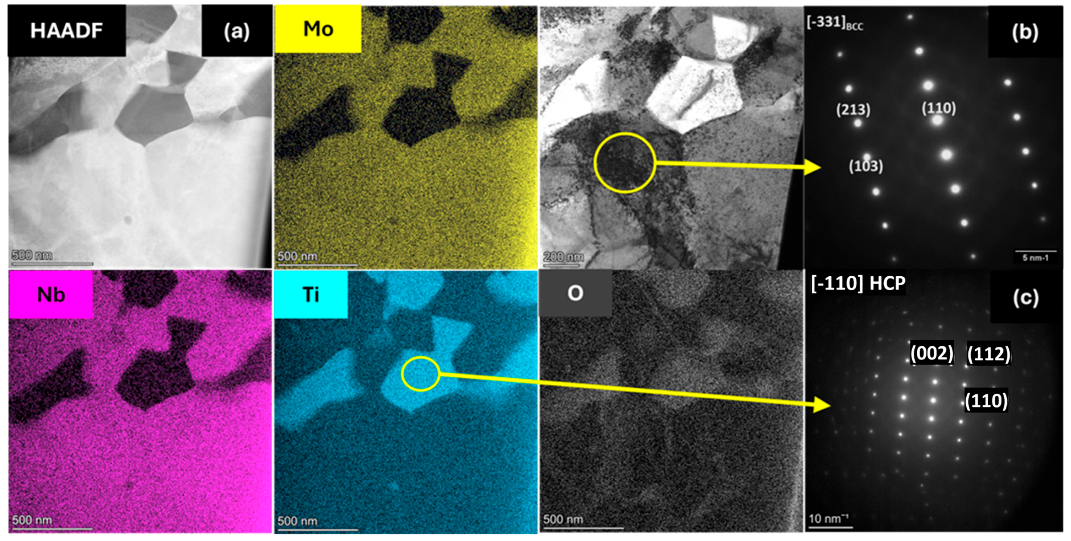
Figure 1. (a) Microstructural and microchemical analysis of MoNbTi alloy showing the existence of matrix and Ti-rich phases; (b,c) respective SAED analyses of matrix and Ti-rich phase.
Metals 15 00989 g001
Figure 2. Microstructural and microchemical analysis of MoNbTiZr alloy showing the existence of matrix and microsegregation of Ti along with Zr.
Metals 15 00989 g002
Figure 3. (a,d) STEM-EDS elemental maps of (base + CrV) alloy showing the existence of matrix, Ti- and Cr-rich phases; (b,c,e) respective SAED analyses of the matrix, the blue circle indicates the region from where the SAD pattern (e) was taken. Ti- and Cr-rich phases showing their BCC, FCC, and C15 structures.
Metals 15 00989 g003
Figure 4. (a) STEM-EDS elemental maps of (base + VZr) alloy showing the existence of matrix and TiZr-rich phases; (b,c) respective SAED analyses of the matrix and Ti-rich phases showing their BCC and HCP structures.
Metals 15 00989 g004
Figure 5. (a) Mean implantation depths calculated at selected energies for each RMPEA. The dashed line represents the calculated average implantation depths across all RMPEAs. (b) SRIM simulation performed for the base + VZr alloy irradiated with 10 MeV Si.
Metals 15 00989 g005
Figure 6. The first positron lifetime components and their associated intensities before irradiation (a,b) and after irradiation (c,d). For base + Zr, note that data points beyond 6 keV are missing due to beamline issues, however, since the lifetime begins to plateau, we assume τ 1 to be in the neighborhood of 203 ps.
Metals 15 00989 g006
Figure 7. Doppler broadening S(E) profiles for (a) as-cast and (b) irradiated samples representing defect content as a function of energy and depth.
Metals 15 00989 g007
Figure 8. τ 2 lifetimes for (a) as-cast and (c) irradiated samples and their intensities (b) and (d), respectively. In practice, about 2 or 3 lifetime components are measurable, however, the intensity components of base + Al and base + Zr appear to be weak but are non-zero.
Metals 15 00989 g008
Figure 9. Bulk normalized S-W curves for as-cast RMPEAs. The surface, sub-surface, and bulk labels serve as a guide for identifying distinct regions within the sample. The arrows indicate the direction of increasing positron implantation energy. The datum at (1, 1) marks positron implantation in the sample bulk, measured at 30.05 keV.
Metals 15 00989 g009
Figure 10. (a) Lifetime measurements featuring τ 1 and τ 2 lifetime components, plotted as a function of chemical complexity for as-cast and irradiated samples. (b) DBS S-parameter measurements as a function of chemical complexity.
Metals 15 00989 g010
Figure 11. TEM BF image of base alloy showing nanotwins along with STEM-EDS map showing Ti enrichment in the phase.
Metals 15 00989 g011
Figure 12. Change in overall defect content after irradiation plotted as a function of energy and depth.
Metals 15 00989 g012
Figure 13. S-W plots for as-cast samples and irradiated samples measured at e + implantation energy of 10   keV . The linear fits are calculated to highlight the evolution of defect structure as a result of damage induced by 10   MeV   Si + ions. Since S-W curves of both as-cast and irradiated samples have different slopes this indicates a change in defect structure after irradiation. Adapted from ref. [30].
Metals 15 00989 g013
Table 1. The elemental composition of the as-cast samples used in this study.
RMPEAMoNbTiVCrZrAl
MoNbTi32%31%37%
AlMoNbTi37%35%18% 10%
MoNbTiZr22%25%30% 23%
CrMonbTiV17%18%21%22%22%
MoNbTiVZr18%19%21%24% 18%
Table 2. Positron Lifetime values for defect-free constituent elements, compiled experimentally by Robles et al. and is adapted from Ref. [33]. The lifetimes of the pure elements are used to estimate bulk ( τ b , a v g ) and monovacancy ( τ m , a v g )   lifetimes of each RMPEA.
ElementBulk (ps)Monovacancy (ps)RMPEA Estimated   τ b , a v g (ps) Estimated   τ m , a v g (ps)
Mo106170MoNbTi126.62201.64
Nb120210MoNbTiZr136.04214.46
Ti150222AlMoNbTi124.72200.76
V124191MoNbTiVZr132.66208.32
Cr120150CrMoNbTiV124.80210.78
Zr164252
Al165244
Disclaimer/Publisher’s Note: The statements, opinions and data contained in all publications are solely those of the individual author(s) and contributor(s) and not of MDPI and/or the editor(s). MDPI and/or the editor(s) disclaim responsibility for any injury to people or property resulting from any ideas, methods, instructions or products referred to in the content.