Abstract
The keyhole defect located at the termination of the friction stir welding (FSW) seam of 6082 aluminum alloys was repaired utilizing the refilling friction stir spot technique. This study examined the impact of the plunge depths on the microstructure of the welding spot. The results show that under the action of shear stress introduced by the pin, the (111)[10] shear texture and (112)[11] Copper texture were formed. The formation of (001)[100] Cube and (001)[310] CubeND textures was due to the occurrence of discontinuous dynamic recrystallization. When the plunge depth of the sleeve was 1.0 mm, the volume fraction of deformed grains in the welding spot reached 45%, and the tensile strength of the welding spots was 184 MPa. When the plunge depth of the sleeve was 1.5 mm, the tensile strength of the repaired spot welding was 210 MPa, which was basically equal to the strength of the FSW seam.
1. Introduction
Utilizing lightweight aluminum alloys for structural components can contribute to a reduction in weight in structural parts. This approach may offer potential solutions to energy and environmental pollution challenges. The primary alloying constituents of the 6082 aluminum alloy were magnesium and silicon. Upon rolling, this alloy exhibited superior specific strength, machinability, and corrosion resistance, rendering it highly prevalent in both aerospace and automobile industries []. Friction stir welding (FSW) represents an innovative welding technique that facilitates material jointing in the solid phase state, utilizing frictional heat and plastic deformation. This method enabled the joining of a variety of materials, including aluminum alloys [], magnesium alloys [], titanium alloys [], steel materials [], and dissimilar metals []. During the welding process, dynamic recrystallization occurred, and the coarse grains of the base material were refined []. This process was similar to refilling friction stir spot welding (RFSSW) [,,] and linear friction welding [,,]. FSW, with its expansive potential applications in the industrial field, was significantly influenced by certain process parameters. These include the rotation speed, welding speed, and inclination angle. Notably, these parameters have a profound impact on the microstructure and mechanical properties of weld seam. As the rotation speed increased, there was a corresponding increase in the degree of dynamic recrystallization. Consequently, the grain size within the weld became finer, leading to an enhancement in tensile strength from 213 MPa to 227 MPa []. The flowability of the material during welding significantly influenced the strength of the weld seam. Notably, enhanced flowability and strain on the upper surface of the weld seam could restrict the proliferation of intermetallic compounds. This led to a tensile strength of 251.81 MPa at the top surface. In contrast, the tensile strength at the bottom of the weld seam was considerably lower, registering at 220 MPa []. Notably, the precipitate-free zone within the heat-affected zone (HAZ) was predominantly responsible for weld bead failure []. Kun Gao et al. [] demonstrated that enhancement in the properties of the weld resulted from increased uniformity of the weld’s microstructure, elimination of hook defects, reduction in stress concentration, and a decrease in the solid solubility of strengthening phases within the thermo-mechanically affected zone (TMAZ). Nevertheless, the presence of a keyhole diminished the load-bearing area of the weld seam during service, thereby reducing the joint performance. For straight welding seams, a backing plate can be added before welding and removed after welding (similar to the arc plate and arc extinguishing plate in fusion welding), and then, the backing plate can be cut off, eliminating the keyhole. For circular welding seams, it is difficult to eliminate the keyhole, so the repair of the keyhole is particularly important.
Bing Han [] utilized the friction bit joining technique with AA7075 as the drill bit material to rectify a keyhole in a 7.8 mm thick AA2219 aluminum alloy FSW. Post-repair, the tensile strength of the weld was equivalent to 96.6% of that of a defect-free joint. Xiangchen Meng [] employed a hybrid approach, combining tungsten inert gas arc welding and friction stir processing, to address the keyhole. Initially, the molten metal from the tungsten inert gas arc welding was utilized to fill the keyhole. Subsequently, the dynamic recrystallization during the friction stir processing refined the grain structure, enhancing the strength of the weld spot. Utilizing electromagnetic induction as a heat source, the selective cladding technique was employed in the rectification of keyhole defects []. Martin Reimann et al. [] employed the RFSSW technology to rectify keyhole defects in the FSW of both 7075 [] and 2219 [] aluminum alloys. This technique involves inserting a plug into the keyhole defect, with the pin and sleeve subsequently generating frictional heat on the plug and the upper surface of the weld seam. The next step entails pressing down the sleeve, prompting the plastic metal to flow into the cavity created by the rising pin. The process was concluded by pressing down the pin (and raising the sleeve) to refill the plastic metal into the weld seam, thereby effectively repairing the FSW keyhole defect [].
Crystal texture refers to the quantitative orientation distribution of grains within polycrystals. The specific type and volume composition of this texture can provide insights into the deformation mechanisms of polycrystals []. In aluminum alloys characterized by high stacking fault energy, slip on dislocations was more likely to occur under plastic deformation conditions. As the dislocation reaction progressed, there was a rapid restoration of the material’s microstructure, leading to alterations in the texture components []. The process of recrystallization can induce alterations in the texture of a crystal. Such modifications can be attributed to several factors, including variations in storage energy in grain, the migration of grain boundaries, and misorientation [,]. Therefore, it was particularly important to reveal the texture evolution process during RFSSW. This study employed the RFSSW technique to address keyhole defects located at the terminal of the FSW in a 2 mm thick 6082 aluminum alloy. The electron backscattered diffraction (EBSD) method was utilized to analyze the grain orientation, grain boundary configuration, and texture type across various regions of the welding spot. Furthermore, this study primarily investigated the influence of plunge depth on the microstructure of a repaired welding spot.
2. Materials and Methods
The base material (BM) used in this study was a 2 mm thick 6082-T6 aluminum alloy sheet, with the following chemical composition: Si 0.97, Mg 0.67, Cu 0.07, Ti 0.01, Fe 0.37, Cr 0.01, Zn 0.06, and balance Al (all in mass%). Table 1 presents the geometric dimensions of the tool utilized in FSW, along with the corresponding welding process parameters. Similarly, Table 2 delineates the tool dimensions and welding process parameters associated with RFSSW. A comprehensive schematic illustrating the keyhole repair process was depicted in Figure 1. First, the plug was placed in the keyhole, as shown in Figure 1a,b; the pin, sleeve, and clamping ring were pressed down to the upper surface of the workpiece, as shown in Figure 1c. Upon initiating the welding machine, both the pin and sleeve commence their rotation. They generate heat through frictional contact with the welding seam metal and plug metal, thus transitioning into the preheating phase, illustrated in Figure 1d. During the plunging stage, the sleeve begins to press down, forcing the newly formed plastic metal into the cavity created by the upward movement of the pin, as depicted in Figure 1e. In the retracting stage, the pin descends as the sleeve retracts, pushing the malleable metal into the cavity created by the sleeve’s withdrawal, as depicted in Figure 1f. Upon completion of the repair, the sleeve, pin, and clamping ring were lifting, as shown in Figure 1g. The solder joints, devoid of keyhole defects post-repair, were illustrated in Figure 1h. The rotational speed of both the sleeve and the pin remained consistent throughout the repair process. Consequently, there was no relative rotational motion between the sleeve and the pin in the direction of rotation. The speed at which the pin was plunged or retracted was contingent upon the geometric dimensions of both the sleeve and the pin in correlation to the sleeve itself. In the plunging stage of the sleeve, the volume of the cavity, which was formed by the retracting of the pin, equates to the volume of the plunging of the sleeve. Consequently, if the plunging speed of the sleeve was 1.2 mmps, then the corresponding retracting speed of the pin was 0.8 mmps. The plunge depth of the sleeve controlled the volume of plastic metal and the heat input during the welding process. In this study, the depths of the sleeve were set to 1 mm, 1.5 mm, and 2 mm, respectively. Preliminary experiments revealed that a plug volume slightly exceeding that of the keyhole yielded optimal repair results. The plug was fabricated from 6082 bar stock, boasting an original diameter of 10 mm. Subsequent to mechanical processing, the plug assumes a conical shape, featuring a diameter of 2.3 mm at the upper extremity, 2 mm at the lower extremity, and a height of 3.2 mm. For the weld spot that had been repaired, a wire cutting method was employed to procure metallographic and EBSD samples. Subsequently, the metallographic samples were ground using sandpaper and mechanically polished. Upon completion of these steps, they were etched with Keller reagent, prepared with 95 mL of water, 2.5 mL of HNO3, 1.5 mL of HCl, and 1.0 mL of HF. After corrosion with Keller’s reagent, the macroscopic metallography of the weld joint was observed using a binocular metallographic microscope (CaiKon 4XB, CaiKon, Shanghai, China). After rough sanding and mechanical polishing of the EBSD sample surface, electrolytic polishing was used in a 10% perchloric acid anhydrous ethanol solution at 20 V and −20 °C over 40 s. EBSD experiments were conducted using a scanning electron microscope (Quanta 450 FEG, FEI, Portland, OR, USA) with an EBSD probe (Oxford Instrument Symmetry S2, Oxford, UK ). In EBSD detection, the step size was 0.8 μm and the test voltage was 20 kv. The texture was represented as (h k l)[u v w], where (h k l) denoted the crystal plane orthogonal to the shear plane normal (SPD), and [u v w] indicated the crystal direction concomitant with the shear direction (SD). The average grain size was ascertained using the equivalent diameter method. To avoid confusion, the term “weld seam” in this paper refers to the FSW weld seam. The repaired weld seam was referred to as a “welding spot”, as shown in Figure 1.

Table 1.
Friction stir welding conditions.

Table 2.
Refilling friction stir spot welding conditions.

Figure 1.
FSSW keyhole closure process: (a) plug and keyhole of FSW; (b) plug in keyhole; (c,d) preheating stage; (e) plunging stage; (f) retracting stage; (g) pin, sleeve, and clamping ring lifting stage; (h) closed keyhole.
3. Results
3.1. Microstructure of Base Metal and Plug
Figure 2a depicts the grain morphology and grain boundary composition of the base material for the 6082 aluminum alloy. The average grain size of this base material was 25 μm. The microstructure of the plug is shown in Figure 2b, and the plug exhibits a banded structure after drawing.
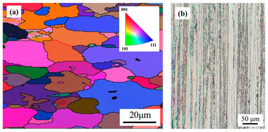
Figure 2.
Microstructure: (a) 6082 aluminum alloy sheet; (b) 6082 aluminum alloy plug.
3.2. Macrostructure of the Welding Spot with Closed Keyhole
Upon completion of FSW, the tool was positioned upwards, and the pin was withdrawn from the base material. This process results in a keyhole defect at the termination of the welding seam, as shown in Figure 3a. The technique of RFSSW was employed to repair the keyhole. This research examined the influence of the plunge depth on the surface formation and microstructure of the welding spot. As evidenced by Figure 3b–d, the formation of the upper surface of the welding spot exhibited high quality across all parameters. This phenomenon arises because the pin and sleeve, which rotate during the repair process, consistently contact the upper surface metal of the welding spot. This continuous interaction results in a high temperature at the upper surface of the welding spot and promotes strong material flow.
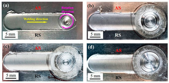
Figure 3.
Surface topography of welding spot at different plunge depths: (a) keyhole; (b) 1 mm; (c) 1.5 mm; (d) 2 mm.
Figure 4 depicts the macroscopic cross-sectional appearance of the welding spot following the repair of a keyhole defect using RFSSW. The microstructure of the advancing side (AS) and the retreating side (RS) of a FSW exhibited discernible differences, attributable to the asymmetric material flow on each side of the weld seam. The strain rate on the AS was notably higher than that on the RS. Consequently, the grain size gradient of the TMAZ on the AS was significantly larger, resulting in a more pronounced boundary of the TMAZ on the AS []. Figure 4 illustrates that the microstructures of the AS and RS in the welding spot were strikingly similar. This similarity could be attributed to the fact that, during the repair process, neither the pin nor the sleeve partakes in the traveling process. Consequently, the flow of plastic metal in the welding spot remains symmetrical. The welding spot can be divided into four different regions: stirred zone (SZ), HAZ, TMAZ, and base material. The SZ can be further divided into sleeve-SZ (S-SZ) and pin-SZ (P-SZ). The rotating pin consistently contacted the upper surface of the welding spot metal, resulting in a high temperature and substantial material fluidity on the welding spot upper surface. This process allowed for the thorough blending of the plug metal and welding seam metal, creating a mechanically interlocked structure. When the sleeve depth was 1.0 mm, the welding spot exhibited insufficient heat input at its base, leading to partial plasticization of the plug. Notably, there were discernible cracks at the interface between the plug metal and the weld seam metal situated at the bottom of the welding spot, as illustrated in Figure 4a. In the S-SZ, an onion ring structure similar to that in the FSW weld was revealed, as shown in Figure 4a. This phenomenon arose due to the high linear velocity and heat generation at the lower end of the sleeve during refilling. Consequently, the welding spot at the center of the sleeve’s action area exhibited the highest surface temperature. This leads to intense plastic metal flow while the surrounding metal, in contrast, remains at a lower temperature and exhibits inferior flow. The disparity in plastic flow gave rise to the formation of a distinct plastic flow layer. In the refilling process, the upper-layer metal drove the flow of the lower-layer metal, consequently forming an onion ring structure. As the sleeve plunge depth increased, there was a corresponding rise in the welding heat input. This resulted in a narrowing temperature difference between the S-SZ and the P-SZ. Consequently, the arc at the junction became smoother. This process gave the welding spot a distinct basin-shaped morphology, as illustrated in Figure 4b,c. When the sleeve depth was 1.5 mm, there was a notable increase in heat input, which led to an expansion in the volume of the plastic metal. This subsequently enhanced material flowability, allowing the plug metal to thoroughly amalgamate with the weld seam metal. Consequently, the flow range of the plug metal broadened, resulting in a layered structure at the bottom of the welding spot, where the plug metal interchanged with the weld seam metal. When the pressing depth of the sleeve increased to 2 mm, given that the base material thickness was also 2 mm, an aluminum alloy pad was incorporated between the welding seam and the welding platform. This measure was essential to prevent potential damage to the welding machine that could arise from the contact between the sleeve and the welding platform. During the repair process, some of the pad material was plasticized and flowed into the bottom of the weld spot, as shown in Figure 4c. When the plunge depth of the sleeve reached 2 mm, the plug metal was refilled into the upper layer of the welding spot, as illustrated in Figure 4c. It can be inferred that during the plunging stage, the heat output increased, the metal flow was strong, and the plasticized plug metal was extruded to the vicinity of the pin. During the retracting stage, the plug metal was reflowed into the upper layer of the welding spot, as shown in Figure 4c.
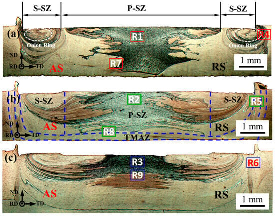
Figure 4.
Macroscopic cross-sectional images at different plunge depths: (a) 1 mm; (b) 1.5 mm; (c) 2 mm.
As the plunge depth of the sleeve increased, there was a corresponding rise in the heat input during the welding process []. This enhanced the fluidity of the metal material, causing the plug metal to converge towards the upper surface of the welding spot. As the temperature differential diminished between P-SZ and S-SZ, the lamellar structure within the S-SZ became notably smoother. Consequently, the lamellar plug metal interspersed with the welding seam metal in the welding spot, creating a mechanically interlocked structure.
3.3. Microstructure of the Welding Spot with Closed Keyhole
3.3.1. Stirring Zone of the Upper Layer
The microstructure of the three regions proximate to the upper surface in P-SZ, denoted as R1, R2, and R3, was analyzed using EBSD for welding spots subjected to varying plunging depths within the sleeve. This region was predominantly characterized by fine equiaxed grains, with adjacent grains exhibiting similar orientations, as depicted in Figure 5. This indicates that high-angle grain boundaries (HAGBs) were formed by increasing the orientation difference in sub-grains, which were formed by the aggregation and rearrangement of dislocations. This process was known as continuous dynamic recrystallization (CDRX), where dislocations annihilate at high speeds during the recrystallization process and develop into sub-grain boundaries and low-angle grain boundaries (LAGBs), forming HAGBs by further absorbing deformation storage energy []. In aluminum alloys characterized by high stacking fault energy, the extended dislocations were notably narrow and exhibit a propensity to bundle. This bundling made it challenging for the dislocations to decompose. Consequently, these dislocations were more likely to undergo mutual cancelation and annihilation via mechanisms such as cross-slip and climb. Such processes increased the probability of CDRX, leading to a distinct zigzag morphology at the grain boundaries []. The presence of serrated boundaries in the P-SZ, proximate to the upper surface, suggested that there was a CDRX of the plastic metal in this region during the refilling process. This was concomitant with the migration of grain boundaries []. The CDRX process closely resembles the geometric dynamic recrystallization (GDRX) process. Both processes were characterized by the transformation of LAGBs within grains into HAGBs. During GDRX, grains underwent elongation due to extrusion forces, resulting in lamellar grain structures with the long axis oriented perpendicular to the applied pressure [,]. This phenomenon of CDRX within the lamellar grains was termed GDRX. Notably, GDRX tends to be more prevalent at lower temperatures [,,]. Consequently, the fine equiaxed sub-grains, which emerged due to the process of GDRX, originate from the identical lamellar parent grain. This led to the same, or very similar, grain orientation among adjacent equiaxed grains, as shown in Figure 5a. When the plunge depth of the sleeve was 1.0 mm, the fine equiaxed grains were arranged in a necklace shape and have similar grain orientation, as shown by the black dotted line in Figure 5d. When the plunge depth of the sleeve reached 1.5 mm, the arrangement of grains in a necklace-like pattern became less pronounced, as shown in Figure 5b. This was attributed to the increased welding heat input corresponding to the increase plunge depth. Consequently, the primary mode of recrystallization shifted towards CDRX, resulting in an average grain size of approximately 8 μm. In region 2, an abnormal growth of grains was also observed, resulting in the formation of coarse grains with an approximate size of 33 μm highlighted by the black arrow in Figure 5f. This phenomenon arose from the dissolution of second-phase particles in the 6082 aluminum alloy during the welding process. As these particles dissolved into the weld metal, their pinning effect on grain boundary migration diminished. Consequently, this reduction led to the abnormal growth of individual grains [].
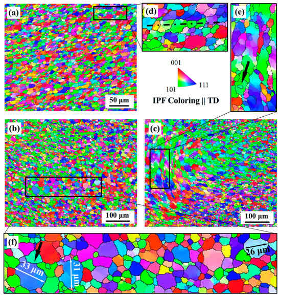
Figure 5.
Grain orientation mapping of upper layer at different plunge depths: (a) 1 mm; (b) 1.5 mm; (c) 2 mm; (d–f) show local amplification.
Upon increasing the plunge depth to 2.0 mm, an onion ring structure, a hallmark feature of the nugget zone in FSW, was observed in region 3, as shown in Figure 5c. There was a range of opinions regarding the causes of onion ring formation. It was generally believed that due to the periodic adhesion between this plastic metal layer and the adjacent plastic metal layer during the welding process, there was a large strain gradient within the plastic metal layer, leading to changes in the microstructure of the metal within the layer, further forming an onion ring structure []. The creation of onion rings was associated with the dynamic flow of materials that occurs during the welding process. The horizontal flow generated by the shoulder transitioned from AS to RS, while the convectional flow, induced by the threaded probe, preceded the tool. This resulted in the material in the upper plate being drawn downwards by the shoulder’s downforce. Consequently, an onion ring configuration emerged as a result of the loads exerted by both external and internal screws with each rotation [,]. The observation of an onion ring structure in region 3 indicated that, at a plunge depth of 2.0 mm for the sleeve, there was significant formation of plastic metal, accompanied by a high degree of plastic flow in the weld spot. In this region, elongated grains were still present. Notably, the long axis of these grains aligned with the vertical direction, contrasting with region 1 where the elongated grains were oriented along the horizontal direction. This phenomenon arose due to the dual motion of the pin during the refilling process, in which it not only exerts a downward pressure but also undergoes rotation. The impact of the pin’s bottom end on the upper surface of the plastic metal was twofold: it generated an extrusion force in the vertical direction and a frictional force tangential to the surface of the pin column. Furthermore, the frictional force progressively intensifies from the center to the periphery of the pin, with a larger diameter corresponding to an increased linear speed. At a plunge depth of 1.0 mm, there was a reduction in the formation of plastic metal at the welding spot. This impediment affected the transmission of friction force downward. Consequently, the dominant force became the extrusion force directed vertically. This results in the grains being compressed into a strip shape. Hence, the long axis of the strip-shaped grains in region 1 aligned along the horizontal direction. At a plunge depth of 2.0 mm, there was a noticeable increase in the heat input during welding, leading to the formation of a substantial amount of plastic metal at the welding spot. The pin, under the influence of frictional forces, induced rotation in the upper layer of metal. This rotating upper layer subsequently caused the adjacent lower layer of metal to rotate. The rotational speed of the plastic metal was governed by frictional forces. Figure 6a presented a schematic diagram illustrating the metallic force in proximity to the pin. Conversely, Figure 6b depicted the plastic flow of the metal on the upper surface of the welding spot. As one moves from the upper surface of the welding spot to the bottom, there was a sequential decrease in the rotational speed of the plastic metal. Notably, the rotational speed at the pin edge position surpasses that at the center position. The flow of plastic metal during refilling can be likened to a vortex, with its flow schematic diagram depicted in Figure 6c. As the plastic metal rotated, friction between the layers induced grain elongation along the vertical direction. This resulted in the long axis of the elongated grains in region 3 aligning with the vertical direction. The emergence of island-like grains within elongated grains was attributed to the presence of second-phase particles in the alloy, which inhibited the migration of grain boundaries []. Consequently, small grains proximate to the second phase were preserved within the larger grains, leading to the formation of island-like structures, as shown by the black arrow in Figure 5e.

Figure 6.
Schematic diagram of plastic metal stress and flow. (a) Force on the metal at the bottom of the pin; (b) plastic metal flow on the upper surface (first layer plastic metal flow); (c) plastic metal flow in the vertical direction.
The mean grain sizes for regions 1, 2, and 3 were found to be 8 um, 6 um, and 7.52 um, respectively. As the sleeve plunge depth augments from 1.0 mm to 1.5 mm, there is a concomitant increase in the degree of plastic deformation, which in turn hoards greater deformation energy within the grains. This surplus energy augments the driving force for recrystallization, culminating in an elevated degree of recrystallization and further refinement of the grains. As the plunge depth escalates from 1.5 mm to 2.0 mm, a concomitant rise in temperature was observed in the weld spot area, coupled with a trend towards grain growth []. Consequently, as the plunge depth of the sleeve intensifies, the grain size demonstrates an initial decrease, followed by a subsequent increase.
3.3.2. Thermo-Mechanically Affected Zone
Figure 7a–c show the grain orientation mapping of TMAZ at different plunge depths. The TMAZ, functioning as an intermediate region between the S-SZ and the HAZ, demonstrated elongated grains on the side bordering the HAZ. Conversely, the side closer to the S-SZ primarily consisted of fine equiaxed grains. Furthermore, the adjacent grains shared similar orientations, as shown in Figure 7. In the area surrounding the S-SZ region, the outer surface of the sleeve exhibited a higher linear velocity. During the refilling stage, the sleeve maintained a downward pressure on the plastic metal in the ND direction, while also generating a frictional force parallel to the tangent of the outer surface. As one moves from the S-SZ boundary to the HAZ, the force exerted on the metal within the TMAZ diminished progressively, creating a gradient effect. This resulted in the formation of a plastic metal flow layer. This layer of plastic metal was typically arc-shaped, plastic metal flow traces as shown by the black dotted lines in Figure 7a. The degree of recovery and recrystallization was determined by the magnitude of the distortion energy stored within the metal layer. Within the perimeter of the HAZ, the deformation of the metal was minimal, characterized by a low strain rate and inadequate shear force to reactivate the slip system. Consequently, there was a small amount of stored distortion energy, which led to a reduced degree of recrystallization and resulted in elongated grain structures. In the region adjacent to the S-SZ, the metal was directly compressed, and friction was created by the external edge of the sleeve, leading to a high strain rate and elevated temperature. This induced extensive recrystallization, characterized by the reformation of fine equiaxed grains within the elongated grains. Furthermore, the adjacent grains exhibit similar orientations, suggesting the occurrence of GDRX in this region. Due to the influence of welding thermal cycles, there has been additional growth in the grains within the HAZ. With the increased plunge depth, the heat input increased during the welding process, the temperature in the TMAZ rose, and the amount of plastic metal increased. The plastic metal cannot transfer the extrusion force and frictional force from the edge of the sleeve to the TMAZ. Therefore, as the plunge depth increased, the TMAZ became smaller, as shown in Figure 4 and Figure 7.
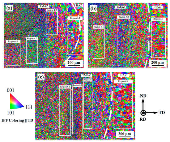
Figure 7.
Grain orientation mapping of TMAZ at different plunge depths: (a) 1 mm; (b) 1.5 mm; (c) 2 mm.
Heat and deformation can induce alterations not only in the microstructure but also in the morphology of texture evolution []. The evolution of texture can be indicative of the flow and strain experienced by plastic metal during the welding process []. The stress in the TMAZ gradually diminished from the adjacent S-PZ zone to the HAZ, subsequently leading to the formation of grains with varying orientations. Therefore, polar stereographic projections of grains at different positions in the TMAZ were conducted to observe the preferred orientation of grains. The specific positions were marked as region 4.1, region 4.2, region 4.3, and region 4.4 in region 4; region 5.1, region 5.2, and region 5.3 in region 5; and region 6.1, region 6.2, region 6.3, and region 6.4 in region 6, as shown in Figure 7. Within the TMAZ, the shear plane normal (SPN) was parallel to transverse direction (TD), and shear direction (SD) was parallel to rotation direction (RD) []. Figure 8a–c showed the polar stereographic projection of TMAZ at different plunge depths. The texture type of TMAZ was determined by comparison with the ideal pole figure, utilizing various symbols to denote the position of the ideal texture within the pole figure. For instance, a small square represents the (001)[100] standard texture, while a triangle symbolizes (111)[11], as shown in Figure 8. Through a comparative analysis, it was found that the primary textures present in TMAZ were (111)[11] shear texture and (001)[100] Cube texture (110)[001] Goss texture, (111)[10] shear texture, (001)[310] CubeND texture, (112)[11] Copper texture, and (001)[110] rotated Cubic texture. Texture formation was driven by two primary factors. The first involved energy change as dislocations coalesce and anneal, culminating in the creation of LAGBs. These subsequently evolved into HAGBs, leading to a decrease in both grain size and deformation storage energy. The second factor pertained to the preferential activation of slip systems throughout the recrystallization process []. In materials possessing a face-centered cubic (FCC) structure, shear texture was generated through the rotation of the lattice. The shear plane aligned parallel to the {111} crystal plane, while the SD was parallel to the <110> crystal orientation. In the FSW process, the SD aligned with the tangent direction of the pin’s surface, while the shear plane corresponds to the cutting plane along the rotational trajectory of the same surface. Consequently, distinct positions within the welding seam exhibited varied shear directions and planes. The SD and the SPN in the TMAZ of the RFSSW were similar to FSW []. In region 4, the SD aligned with RD, while SPN was oriented parallel to TD. In metals with FCC structure, the {111} <110> slip system was preferentially activated during plastic deformation []. Consequently, the (111)[10] shear texture was initially formed under the external shear action on the sleeve. The torsional stress within the crystal lattice can diminish the distortion energy within the grains, subsequently influencing the formation of the texture. As the sleeve continued to exert pressure, the grain rotated at a specific angle. When the (111)[10] texture rotated 45 deg along the [001] direction, it formed a (110)[001] Goss texture. When it rotated 18 deg along the [111] direction, it formed a (111)[11] shear texture. In the rolling process of aluminum alloys, the (111)[10] shear texture underwent a 45-degree rotation along the [001] direction, resulting in the formation of the (110)[001] Goss texture []. The presence of (110)[001] Goss texture indicated that the deformation behavior of the metal within the TMAZ resembled the characteristics of rolling. Thermoplastic metals underwent plastic deformation while also recrystallizing, with the processes of nucleation and grain growth occurring during the discontinuous dynamic recrystallization (DDRX) []. Given the benefits of (001)[100] Cube oriented grains in both nucleation and grain growth [,,], the formation of a recrystallized (001)[100] Cube texture in hot-worked metals was facilitated. During the recovery stage, equiaxed sub-grains with cubic orientation have already begun to form around the dislocation walls. Sub-grains with other orientations exist in the form of layers or triangles. Consequently, the cubic oriented grains exhibited a high nucleation rate []. The (001)[100] Cube oriented grains possessed minimal storage energy, and consequently, exhibited a high boundary migration rate. These grains grew primarily through the strain-induced boundary migration mechanism []. During this growth process, the Cube (001)[100] oriented grains consumed other oriented grains that had a higher storage energy []. During the welding thermal cycle process, sub-grains oriented towards (001)[100] Cube preferentially nucleate at grain boundaries and growth through grain boundary migration in the recovery stage. Under the action of welding thermal cyclic, sub-grains with (001)[100] Cube oriented were preferentially nucleate at grain boundaries. These sub-grains subsequently grow through the migration of the aforementioned boundaries. The appearance of Cube (001)[100] recrystallization texture indicated that DDRX occurs in the TMAZ. In hot-rolled aluminum alloy, nucleation was easy to occur at the second-phase hard particles through a particle-induced nucleation mechanism, and the deformation storage energy near the non-plastic particles enables the nucleation of non-cubic orientation sub-grains [], which in turn forms (001)[310] CubeND texture at the second-phase particles []. During the recrystallization process, the (001)[310] CubeND texture was formed through the consumption of the grains of other orientations.
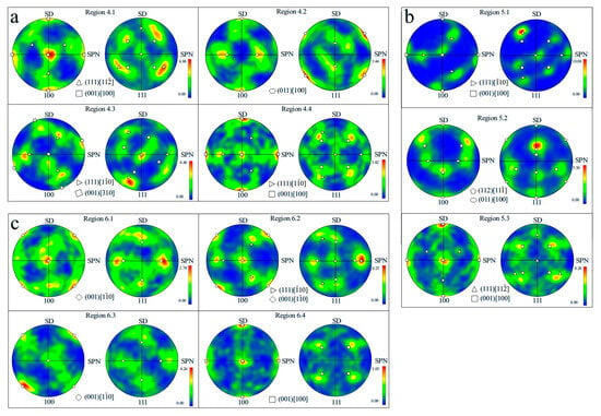
Figure 8.
Polar stereographic projection of TMAZ at different plunge depths: (a) 1 mm; (b) 1.5 mm; (c) 2 mm.
The shear stress diminished progressively from the S-SZ to the HAZ, correspondingly reducing the stored distortion energy within the plastic metal. This resulted in a (111)[10] shear texture in the TMAZ (region 4.4) at the periphery of the HAZ. In contrast, the (111)[10] oriented grains in the other three micro-zones underwent a certain degree of rotation, leading to the formation of (111)[11] shear texture and (110)[001] Goss texture. When the plunge depth was 1.5 mm, the (112)[11] Copper texture and (001)[110] rotation cubic texture appeared in region 5.2. In high-stacking fault energy aluminum alloys, the evolution of texture usually changes along the α-fiber line or the β-fiber line. The β-fiber line includes (112)[11] Copper texture, S texture, and Brass texture []. Konkova T et al. [] showed that aluminum alloys easily formed a (112)[11] Copper texture during hot rolling. This may be the main reason for the presence of (112)[11] Copper texture in region 5.2. Regions 5.3 and 6.4, situated within the HAZ, primarily exhibited the (001)[100] Cube texture under the influence of the welding thermal cycle. Notably, the minor presence of (111)[11] texture was also detected in region 5.3.
As the plunge depth of the sleeve increased, there was a corresponding rise in both the welding heat input and the temperature within the TMAZ. Consequently, the metal’s plastic deformation energy was enhanced. Notably, this plastic deformation was predominantly localized in the TMAZ. This localization made the demarcation between the TMAZ and the HAZ more pronounced and vertical. Furthermore, there was an observable trend of increasing average grain size within the TMAZ. The average grain sizes in regions 4, 5, and 6 were 11.36 μm, 12.74 μm, and 14.57 μm, respectively.
3.3.3. Stirring Zone of the Bottom Layer
The heat source in the welding process was derived from the frictional heat produced by the sleeve and the pin. As one moved from the upper surface to the bottom of the welding point (along the ND direction), there was a gradual decrease in both the extrusion force and the frictional force exerted by the pin on the metal. Consequently, the flowability of the plasticized metal diminished, leading to a reduction in temperature. This variation resulted in inconsistent degrees of recrystallization at different positions along the ND direction of the welding spot, which in turn resulted in the microstructure difference in the weld spot in the thickness direction. For this purpose, three distinct intervals, denoted as R7, R8, and R9, located at the bottom of the welding spot, were scrutinized using EBSD to examine the microstructure. The precise locations for these detections were illustrated in Figure 4.
When the plunge depth of the sleeve was 1.0 mm, a banded structure emerged at the bottom of the welding spot, with an approximate width of 450 μm, as shown in Figure 9a. The banded structure was a common characteristic of FSW seams. The width of this structure was roughly equivalent to the distance covered by the rotating pin after completing one revolution. The banded structure formation in the weld seam can be attributed to the intermittent, direct extrusion of the weld metal by the pin. This process activated various slip systems, resulting in the alternating appearance of grains with different orientations within the weld seam [,]. In the refilling stage, the pin did not directly exert pressure on the bottom metal at the welding spot. Instead, it transmitted both the extrusion and friction forces to the bottom metal via the plastic metal of the upper layer. The cause of the banded structure observed at the bottom of the welding spot was analogous to that in FSW, which was due to the alternating appearance of grains with different orientations formed by the initiation of different slip systems during the plastic deformation process. The distinction between the two processes was evident in that, during the FSW, the pin maintains direct contact with the plastic metal. This contact established a direct correlation between the width of the resulting banded structure and the welding process parameters. Conversely, in the RFSSW process, the pin did not engage directly with the metal at the bottom of the welding spot. Consequently, there was no direct linear relationship between the width of the banded structure and the process parameters. A distinct feature was also observed at the bottom of the welding spot, characterized by an alternating pattern of coarse and fine grains along the ND direction, as highlighted by the white dashed line in Figure 9d. The demarcation between the coarse-grained and fine-grained regions was starkly evident, as highlighted by the red dotted line in Figure 9b. The average grain size in the coarse-grained region was 16.82 μm, while that in the fine-grained region was only 9.23 μm. In the friction stir additive manufacturing process, there also existed a phenomenon of alternating coarse and fine grains [,]. This was due to the fact that, during the additive manufacturing process, the pin repeatedly stirred the interlayer region, and the shear force generated by the pin caused the grains in this region to break and form fine grains. In contrast, the intralayer region only experienced one stirring by the pin, resulting in coarse grains. The RFSSW was divided into two stages: the plunging stage and the refilling stage. During the plunging stage, the plastic metal moved upward along the movement direction of the pin, filling the transient cavity formed by the rising of the pin. When the plunge depth of the sleeve was 1.0 mm, only the upper metal of the weld seam extruded into the transient cavity. The plug functions as a unified entity, with the plastic metal on the plug’s upper layer prompting the unformed metal on the lower layer to ascend along the ND direction. This mechanism ensured the comprehensive involvement of all plug metal in the upward movement process. Consequently, the plug metal exhibited a higher degree of plastic deformation compared to the weld seam metal. In the refilling stage, the pin extruded the plastic metal into the transient cavity, formed by the lifting of the sleeve. The pin directly interacted with the plug metal. Under the combined effects of extrusion force and frictional force exerted by the pin, the grains of the plug metal were refined, predominantly consisting of deformed grains. This phenomenon was depicted in Figure 9c. Region 7 was located at the bottom of the welding spot, where the weld seam metal underwent minimal plastic deformation as it was only compressed by the plastic metal during the refilling stage. Consequently, the temperature in region 7 was relatively low, leading to a reduced degree of recrystallization and resulting in the presence of coarse grains. The primary transformation within the coarse-grained region was characterized by geometric dynamic recrystallization, a process during which new grains were generated by the pinching off of the elongated original grains along their long axis direction. This phenomenon was clearly illustrated by the white dotted lines in Figure 9e.
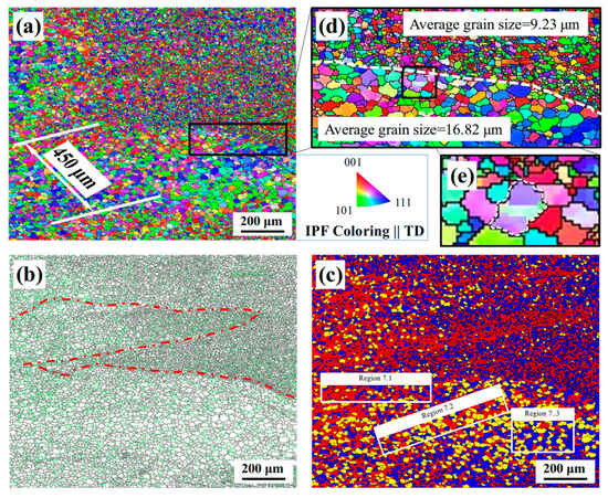
Figure 9.
EBSD images at a plunge depth of 1.0 mm: (a) grain morphology; (b) grain boundary components (green represents small-angle grain boundaries, while black represents large-angle grain boundaries); (c) recrystallized component (blue represents recrystallized grains, yellow represents sub-grains, and red represents deformed grains); (d,e) magnified view of the coarse-fine grained region.
In the Grain Orientation Spread (GOS) image, grains were categorized into three distinct groups based on the average orientation difference within each grain: “Recrystallized”, “Substructured”, and “Deformed”. Grains whose internal average misorientation exceeded 2° (the minimum angle to define a sub-grain boundary) were denoted by “deformed” grains. Also, the grains consisting of sub-grains whose internal misorientation was less than 2°, but in which the misorientation between two adjacent sub-grains was above 2°, were defined as “substructured” grains. All remaining strain-free grains were “recrystallized” [,]. When the plunge depth of the sleeve was 1.0 mm, the volume fraction of deformed grains reached 45%, as shown in Figure 10. As the plunge depth of the sleeve increased, there was a corresponding rise in the heat input during welding. This led to an enhancement in the plastic flow of the metal, resulting in a more uniform mixture of weld seam metal and plug metal. When the plunge depth of the sleeve was 1.5 mm, the fine grain region became a fine grain layer, and only two fine grain layers appear in region 8, as shown in Figure 11a,b. The layer above the fine-grained stratum primarily consisted of recrystallized grains, while the layer beneath it predominantly comprised sub-grains, as depicted in Figure 11c. This can be attributed to the increased plastic deformation and temperature of the upper-layer metal during refilling, leading to a more pronounced degree of recrystallization in this layer. In the region of coarse grains, adjacent grains exhibited similar orientations, as shown by white dotted lines in Figure 11d. This demonstrated that GDRX continued to take place in this region.
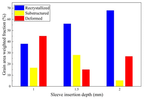
Figure 10.
Fraction of deformed, substructured, and recrystallized grains in the different welding spots.
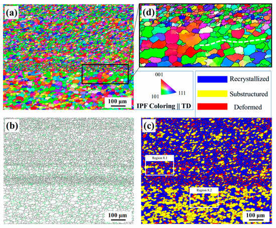
Figure 11.
EBSD images at a plunge depth of 1.5 mm: (a) grain morphology; (b) grain boundary components (green represents small-angle grain boundaries, while black represents large-angle grain boundaries); (c) recrystallized component (blue represents recrystallized grains, yellow represents sub-grains, and red represents deformed grains); (d) magnified view of the coarse–fine-grained region.
When the plunge depth of the sleeve extended to 2.0 mm, there was a more comprehensive intermixing of the plug metal and the weld seam metal. The resultant fine-grained area, which was composed of plug metal, was evenly dispersed within the coarse-grained area constituted by the weld seam metal, as illustrated in Figure 12a,b. From Figure 12a, it was evident that the grain orientation in region 9 differs significantly. Furthermore, the microstructure exhibited axial symmetry along the centerline of the welding spot. The most obvious feature was the appearance of grains with the same orientation (blue color represents the {111} plane of the grain parallel to the TD direction) at equal distances from the center of the weld spot in the upper part of Figure 12a. In the pole stereographic projection of the grains within this region, it was evident that the predominant texture was the (111)[10] shear texture, as shown in Figure 13c. This phenomenon arose from the pronounced fluidity of plastic metal during the refilling stage. For materials possessing an FCC structure, the {111} plane represented the close-packed plane, while the <110> direction identified the close-packed direction. Notably, the Burgers vector, when aligned with the close-packed direction on the close-packed plane, was minimized. This facilitated easy slippage, leading to the formation of a (111)[10] shear texture. At the center of the weld spot, the linear speed of the lower end of the pin was low, the friction force was small, and the plastic metal was mainly extruded by the pin to form elongated grains, with the long axis roughly parallel to TD, as shown in Figure 12d. The quality of plastic metal flow at the weld point’s center was inferior to that at the periphery. Subjected to the welding thermal cycle, the material underwent DDRX, which resulted in the formation of the (001)[100] Cube texture, as shown in Figure 13c. Utilizing the pole stereographic projection method, the grains in the bottom metal of the welding spot were projected under varying plunge depths of the sleeve. The analysis revealed that the primary textures present at the bottom of the welding spot were (111)[10] shear texture, (111)[2] shear texture, (001)[100] Cube, (110)[10] rotated Goss texture, and (011)[11] Brass texture, as depicted in Figure 13a,b.
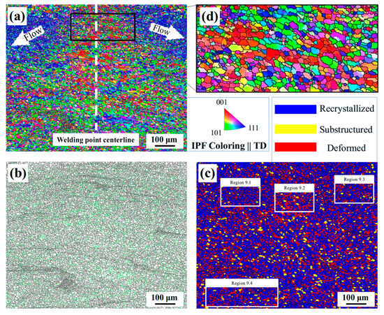
Figure 12.
EBSD images at a plunge depth of 2.0 mm: (a) grain morphology; (b) grain boundary components (green represents small-angle grain boundaries, while black represents large-angle grain boundaries); (c) recrystallized component (blue represents recrystallized grains, yellow represents sub-grains, and red represents deformed grains); (d) magnified view of region 9.
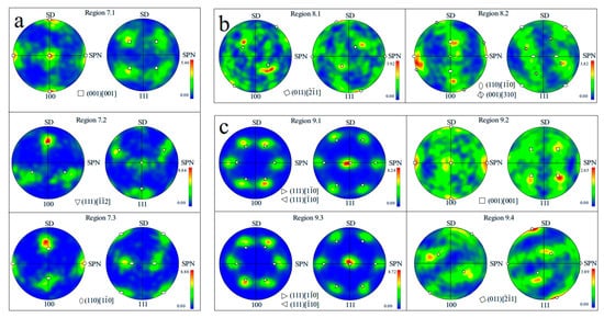
Figure 13.
Polar stereographic projection of bottom layer at different plunge depths: (a) 1 mm; (b) 1.5 mm; (c) 2 mm.
Thermoplastic metals experienced plastic deformation, which resulted in the storage of strain energy within the deformed grains. The presence of the (111)[10], (011)[11] Brass shear texture, and the (110)[10] rotated Goss texture suggested that the stored strain energy in the grains had not been fully released []. As the plunge depth of the sleeve increased, there was a corresponding increase in the welding heat input, leading to an increase in the volume of recrystallized grains, as depicted in Figure 10.
3.4. Tensile Property
Figure 14 showed the tensile properties of different specimens. The BM exhibited a tensile strength of 256 MPa, while the FSW welded seam demonstrated a tensile strength of 209 MPa. Upon examination, it was observed that the tensile strengths of the welding spots corresponded to the plunge depths of the sleeve. When the plunge depths of the sleeve were 1.0 mm, 1.5 mm, and 2.0 mm, the corresponding tensile strengths of the welding spots were 184 MPa, 210 MPa, and 183 MPa, respectively. With the increase in the plunge depth of the sleeve, the tensile strength initially exhibited an upward trend, followed by a decrease. This phenomenon arose due to the minimal heat input when the sleeve depth was 1.0 mm. Consequently, there was incomplete amalgamation between the plug metal and the weld metal at the bottom of the welding spot, leading to the formation of cracks at the interface. These cracks caused the welding spot to rapidly expand along this junction during the loading process, ultimately resulting in joint fracture. When the plunge depth of the sleeve was 1.5 mm, there was a notable increase in the plasticity of the metal. Concurrently, the degree of intermixing between the plug metal and the weld metal intensified. This resulted in a more homogenous microstructure of the weld spot, thereby enhancing its tensile strength. When the plunge depth of the sleeve was 2.0 mm, the heat input of the welding increased, the degree of recrystallization of the metal in the welding spot increased, and the grain size became larger. There were soft orientation factors such as recrystallized Cube textures [], which in turn reduced the performance of the welding spot. When the plunge depth of the sleeve was 1.5 mm, the tensile strength of the repaired welding spot was roughly equivalent to the strength of the FSW seam.
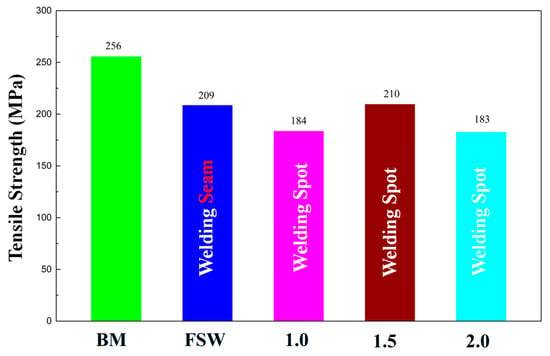
Figure 14.
Tensile properties of each specimen.
4. Conclusions
The keyhole defect located at the termination of the FSW seam was repaired utilizing the RFSSW technique. The grain morphology, orientation, and texture types at various positions within the welding spot were characterized through EBSD technology. An investigation into the impact of the plunge depth on the microstructure of the welding spot was conducted, and the following conclusions were drawn:
- (1)
- During the repairing process, the fluidity of the upper-layer metal in the solder joint was higher than that of the lower-layer metal. The lamellar plug metal alternated with the weld seam metal, forming a mechanically interlocked structure in the upper layer of the welding spot. When the plunge depth was 1.0 mm, the lower plug metal did not achieve complete plasticization due to inadequate heat input. This resulted in crack formation at the bottom of welding spot. As the plunge depth of the sleeve increased, there was a corresponding rise in heat input, which in turn enhanced the plasticity of metal flow. This caused the plug metal to converge towards the upper layer of the welding spot, leading to a reduction in the TMAZ. When the plunge depth of the sleeve reached 2.0 mm, an onion ring structure became apparent in the weld spot.
- (2)
- The shear force exerted by the pin and sleeve caused the plug and weld metal to undergo plastic deformation, thereby storing distortion energy within the grains. This process was further influenced by the welding thermal cycle, which promoted CDRX, resulting in the refinement of the grains. Due to the shear stress introduced by the sleeve, an (111)[10] shear texture was formed in the TMAZ, and an (001)[100] cubic texture and (001)[310] CubeND texture were formed due to the occurrence of DDRX. Within the TMAZ proximate to the weld nugget, there was a noted increase in metal plasticity and elevated temperatures. This environment promoted CDRX, leading to the formation of fine equiaxed grains. Conversely, in the TMAZ adjacent to the HAZ, the degree of recrystallization diminishes. Consequently, the elongated grains, which were formed following deformation, were preserved in this region.
- (3)
- The degree of plastic deformation in the plug metal surpassed that in the weld seam metal, resulting in a more pronounced recrystallization within the plug metal. Consequently, the grain size of the plug metal was reduced in comparison to that of the weld seam metal. This discrepancy gave rise to distinct coarse-grained and fine-grained regions at the bottom of the welding spot. With the increased plunge depth of the sleeve, the metal flow increased, and the mixing of the plug metal with the weld metal was more uniform. The fine-grained area composed of plug metal was evenly distributed in the coarse-grained area composed of weld seam metal.
- (4)
- When the plunge depths of the sleeve were 1.0 mm, 1.5 mm, and 2.0 mm, the corresponding tensile strengths of the welding spots were 184 MPa, 210 MPa, and 183 MPa, respectively. When the plunge depth of the sleeve was 1.5 mm, the tensile strength of the repaired welding spot was roughly equivalent to the strength of the FSW seam. This paper aims to provide a theoretical reference for the repair of keyhole defects in FSW and to accelerate the industrial application of FSW.
Author Contributions
L.Z.: investigation, data curation, and writing—original draft preparation. G.Y.: conceptualization, methodology, project administration, and supervision. All authors have read and agreed to the published version of the manuscript.
Funding
This work was supported by the Lanzhou Talent Innovation and Entrepreneurship Project (No. 2021-RC-51), Science and Technology Program of Gansu Province (No. 21JR7RA545).
Data Availability Statement
The original contributions presented in this study are included in the article. Further inquiries can be directed to the corresponding authors.
Conflicts of Interest
The authors declare no conflicts of interest.
Abbreviations
The following abbreviations are used in this manuscript:
| FSW | Friction stir welding |
| BM | Base materials |
| RFSSW | Refilling friction stir spot welding |
| HAZ | Heat-affected zone |
| TMAZ | Thermo-mechanically affected zone |
| SZ | Stirred zone |
| S-SZ | Sleeve-SZ |
| P-SZ | Pin-SZ |
| EBSD | Electron backscattered diffraction |
| HAGBs | High-angle grain boundaries |
| LAGBs | Low-angle grain boundaries |
| CDRX | Continuous dynamic recrystallization |
| GDRX | Geometric dynamic recrystallization |
| DDRX | Discontinuous dynamic recrystallization |
| RD | Rotation direction |
| TD | Transverse direction |
References
- Hu, D.C.; Wang, L.; Wang, H.J. Dynamic Recrystallization Behavior and Processing Map of the 6082 Aluminum Alloy. Materials 2020, 13, 1042. [Google Scholar] [CrossRef]
- Bush, R.; Feier, I.; Diercks, D. Precipitate Structure, Microstructure Evolution Modeling and Characterization in an Aluminum Alloy 7050 Friction Stir Weld. J. Mater. Eng. Perform. 2025, 34, 12849–12860. [Google Scholar] [CrossRef]
- Song, Y.; Li, W.; Zhang, L.; Wang, N.; Liu, B. Effect of Traveling Speed on Microstructure and Stress Corrosion Cracking of ATZ511 Magnesium Alloy Friction Stir Welded Joints. J. Mater. Eng. Perform. 2025, 34, 12508–12524. [Google Scholar] [CrossRef]
- Su, Y.; Zhou, M.; Li, W.; Yang, X.; Shi, Q.; Xiong, Y.; Wang, P.; Chen, G. Microstructural evolution and mechanical behavior of TA5 titanium alloy joint in low-temperature friction stir welding with various cooling rates. Eng. Fail. Anal. 2025, 176, 109667. [Google Scholar] [CrossRef]
- Dong, J.; Xie, Y.; Meng, X.; Wang, W.; Sun, X.; Wang, P.; Ma, X.; Wang, N.; Wang, Y.; Huang, Y. Microstructural evolution and corrosion responses of friction stir welded SUS301L stainless steel. Mater. Charact. 2024, 214, 114124. [Google Scholar] [CrossRef]
- Huang, W.; Ding, Z.; Li, P.; Zhao, P.; Zhou, D.; Huang, Y.; Meng, X.; Li, Y.; Ma, Y.; Dong, H. Defects response to precoated adhesive in Al/steel friction stir welded joint. J. Manuf. Process 2025, 141, 1109–1118. [Google Scholar] [CrossRef]
- Yu, P.; Wu, C.S.; Shi, L. Analysis and characterization of dynamic recrystallization and grain structure evolution in friction stir welding of aluminum plates. Acta Mater. 2021, 207, 116692. [Google Scholar] [CrossRef]
- Shen, Z.; Ding, Y.; Chen, J.; Amirkhiz, B.S.; Wen, J.Z.; Fu, L.; Gerlich, A.P. Interfacial bonding mechanism in Al/coated steel dissimilar refill friction stir spot welds. J. Mater. Sci. Technol. 2019, 35, 1027–1038. [Google Scholar] [CrossRef]
- Shen, Z.; Ding, Y.; Gopkalo, O.; Diak, B.; Gerlich, A.P. Effects of tool design on the microstructure and mechanical properties of refill friction stir spot welding of dissimilar Al alloys. J. Mater. Process Technol. 2018, 252, 751–759. [Google Scholar]
- Shen, Z.; Chen, Y.; Hou, J.S.C.; Yang, X.; Gerlich, A.P. Influence of processing parameters on microstructure and mechanical performance of refill friction stir spot welded 7075-T6 aluminium alloy. Sci. Technol. Weld. Join. 2015, 20, 48–57. [Google Scholar] [CrossRef]
- Yang, X.; Meng, T.; Su, Y.; Xu, R.; Guo, Z.; Xu, Y.; Ma, T.; Li, W. Effect of initial microstructure on performance and corrosion behavior of GH4169 superalloy joint produced by linear friction welding. Chin. J. Aeronaut. 2025, 38, 103226. [Google Scholar] [CrossRef]
- Dang, M.; Guo, Z.; Ma, T.; Yang, X.; Su, Y.; Li, W.; Li, J.; Vairis, A. Microstructure evolution and mechanical properties of a linear friction welded TC4-DT titanium alloy joint. Mater. Today Commun. 2025, 46, 112684. [Google Scholar] [CrossRef]
- Su, Y.; Yang, X.; Meng, T.; Wu, D.; Xu, R.; Xu, H.; Li, W.; Yin, S. Effect of linear friction welding process on microstructure evolution, mechanical properties and corrosion behavior of GH4169 superalloy. Chin. J. Aeronaut. 2024, 37, 504–520. [Google Scholar] [CrossRef]
- Kumaresh, D.; Venkatesan, S. The effects of tool rotational speed and post-weld heat treatment of friction stir welded AZ31-B magnesium alloy. Eng. Res. Express 2024, 6, 045513. [Google Scholar] [CrossRef]
- You, J.; Zhao, Y.; Miao, S.; Lin, Z.; Yu, F.; Dong, C.; Su, Y. Effects of welding physical fields on the microstructure evolution during dynamic-stationary shoulder friction stir welding. J. Mater. Res. Technol. 2023, 23, 3219–3231. [Google Scholar] [CrossRef]
- Tong, Y.; Dong, B.; Cai, X.; Zhang, H.; Lin, S. Friction stir welding of 2195 AlLi alloy Effect of microstructure on joint failure. Mater. Charact. 2025, 224, 115077. [Google Scholar]
- Gao, K.; Zhang, Z.; Wang, G.; Sun, X.; Zhang, Y. Enhancing metallurgical and mechanical properties of friction stir lap welding of aluminum alloys by microstructure reconstruction. Sci. Rep. 2024, 14, 31987. [Google Scholar] [CrossRef]
- Han, B.; Huang, Y.; Lv, S.; Wan, L.; Feng, J.; Fu, G. AA7075 bit for repairing AA2219 keyhole by filling friction stir welding. Mater. Des. 2013, 51, 25–33. [Google Scholar] [CrossRef]
- Meng, X.; Chen, X.; Han, Z.; Yuan, J.; Xie, Y.; Dong, J.; Xia, P.; Huang, Y. New Technique to Repair Keyhole of 2195 Al-Li Alloy Friction Stir Welding Joints. Materials 2024, 17, 3418. [Google Scholar] [CrossRef]
- Ramon, J.; Pal, M.; Das, B. Investigation of Induction Heating Process for Selective Melting of Aluminum Alloy for the Repair of Exit Hole Defect in Friction Stir Welding Process. Arab. J. Sci. Eng. 2023, 48, 12291–12311. [Google Scholar] [CrossRef]
- Reimann, M.; Goebel, J.; dos Santos, J.F. Microstructure Evolution and Mechanical Properties of Keyhole Repair Welds in AA 2219-T851 Using Refill Friction Stir Spot Welding. J. Mater. Eng. Perform. 2018, 27, 5220–5226. [Google Scholar] [CrossRef]
- Reimann, M.; Goebel, J.; Dos Santos, J.F. Microstructure and mechanical properties of keyhole repair welds in AA 7075-T651 using refill friction stir spot welding. Mater. Des. 2017, 132, 283–294. [Google Scholar] [CrossRef]
- Xie, Q.; Lian, J.; Sidor, J.J.; Sun, F.; Wang, Y. Crystallographic orientation and spatially resolved damage in a dispersion-hardened Al alloy. Acta Mater. 2020, 193, 138–150. [Google Scholar] [CrossRef]
- Mironov, S.; Masaki, K.; Sato, Y.S.; Kokawa, H. Texture Produced by Abnormal Grain Growth in Friction Stir-Welded Aluminum Alloy 1050. Metall. Mater. Trans. A 2013, 44, 1153–1157. [Google Scholar] [CrossRef]
- Kawasaki, M. Different models of hardness evolution in ultrafine-grained materials processed by high-pressure torsion. J. Mater. Sci. 2014, 49, 18–34. [Google Scholar] [CrossRef]
- Mao, D.R.Z. On the dependence of in-grain subdivision and deformation texture of aluminum on grain interaction. Acta Mater. 2002, 50, 4379–4394. [Google Scholar] [CrossRef]
- Liu, X.C.; Wu, C.S. Material flow in ultrasonic vibration enhanced friction stir welding. J. Mater. Process Technol. 2015, 225, 32–44. [Google Scholar] [CrossRef]
- Yuan, Y.; Wu, Z.; Chen, K.; Liu, H.; Huang, H.; Li, Y. Effects of plunge depth on macro-/microstructure and mechanical properties of refill friction stir spot welded 2195-T6 Al–Li alloy. J. Mater. Res. Technol. 2025, 35, 6026–6041. [Google Scholar] [CrossRef]
- Dai, Q.; Ou, S.; Deng, Y.; Fu, P.; Zhang, J. Microstructure evolution and grain size model of 5083 aluminum alloy during hot deformation. Mater. Rep. B 2017, 031, 143–146. [Google Scholar]
- Li, J.; Wu, X.; Guo, J.; Jiang, H. Prediction model of dynamic recrystallization and deformation grain of 6016 aluminum alloy. J. Plast. Eng. 2025, 32, 160–168. [Google Scholar]
- Zhong, H.; Shi, Q.; Dan, C.; You, X.; Zong, S.; Zhong, S.; Zhang, Y.; Wang, H.; Chen, Z. Resolving localized geometrically necessary dislocation densities in Al-Mg polycrystal via in situ EBSD. Acta Mater. 2024, 279, 120290. [Google Scholar] [CrossRef]
- Kassner, M.E.; Barrabes, S.R. New developments in geometric dynamic recrystallization. Mater. Sci. Eng. A 2005, 410, 152–155. [Google Scholar] [CrossRef]
- Mcnelley, T.R.; Swaminathan, S.; Su, J.Q. Recrystallization mechanisms during friction stir welding/processing of aluminum alloys. Scr. Mater. 2008, 58, 349–354. [Google Scholar] [CrossRef]
- Kalinenko, A.; Mishin, V.; Shishov, I.; Malopheyev, S.; Zuiko, I.; Novikov, V.; Mironov, S.; Kaibyshev, R.; Semiatin, S.L. Mechanisms of abnormal grain growth in friction-stir-welded aluminum alloy 6061-T6. Mater. Charact. 2022, 194, 112473. [Google Scholar]
- Ambrosio, D.; Morisada, Y.; Ushioda, K.; Fujii, H. Material flow in friction stir welding: A review. J. Mater. Process. Technol. 2023, 320, 118116. [Google Scholar]
- Yoon, T.J.; Kang, C.Y. Observations on metallurgical phenomena and formation of onion ring nugget during friction stir lap welding of dissimilar aluminum by a new 3D technique. Mater. Lett. 2015, 142, 253–257. [Google Scholar] [CrossRef]
- Yoon, T.J.; Yun, J.G.; Kang, C.Y. Formation mechanism of typical onion ring structures and void defects in friction stir lap welded dissimilar aluminum alloys. Mater. Des. 2016, 90, 568–578. [Google Scholar] [CrossRef]
- Lee, S.; Baek, S.; Lee, S.J.; Chen, C.; Nishijima, M.; Suganuma, K.; Utsunomiya, H.; Ma, N.; Yu, H.Y.; Kim, D. Driving forces of solid-state Cu-to-Cu direct bonding suppressing the work-hardening loss by refill friction stir spot welding. Mater. Sci. Eng. A 2024, 915, 147147. [Google Scholar]
- Chen, S.; Li, Z.; Xiao, J.; Pu, J.; Han, Y.; Gai, S.; Wang, D.; Jiang, X. Experimental investigation of material flow behavior during refill friction stir spot welding. J. Mater. Process Technol. 2025, 337, 118730. [Google Scholar]
- Cao, J.Y.; Wang, M.; Kong, L.; Zhao, H.X.; Chai, P. Microstructure, texture and mechanical properties during refill friction stir spot welding of 6061-T6 alloy. Mater. Charact. 2017, 128, 54–62. [Google Scholar] [CrossRef]
- Li, Y.; Sun, G.; Zhang, Z.; Zhou, L.; Guo, N.; Meng, Q.; Dong, J.; Zhao, H. Texture evolution of refill friction stir spot welding in alclad 2A12-T42 aluminum alloy. Mater. Charact. 2023, 205, 113289. [Google Scholar] [CrossRef]
- Fonda, R.W.; Knipling, K.E. Texture development in friction stir welds. Sci. Technol. Weld. Join. 2011, 16, 288–294. [Google Scholar] [CrossRef]
- Kim, H.W.; Kang, S.B.; Tsuji, N.; Amino, Y.M. Deformation textures of AA8011 aluminum alloy sheets severely deformed by accumulative roll bonding. Met. Mater. Trans. A 2005, 36, 3151–3163. [Google Scholar] [CrossRef]
- Radhakrishnan, B.; Sarma, G.B. Coupled simulations of texture evolution during deformation and recrystallization of fcc and bcc metals. Mater. Sci. Eng. A 2008, 494, 73–79. [Google Scholar] [CrossRef]
- Bennett, T.A.; Kalu, P.N.; Rollett, A.D. Strain-induced selective growth in 1.5% temper-rolled Fe;1%Si. Microsc. Microanal. 2011, 17, 362–367. [Google Scholar] [CrossRef]
- Wang, W.; Helbert, A.L.; Baudin, T.; Brisset, F.O.; Penelle, R. Reinforcement of the Cube texture during recrystallization of a 1050 aluminum alloy partially recrystallized and 10% cold-rolled. Mater. Charact. 2012, 64, 1–7. [Google Scholar] [CrossRef]
- Sidor, J.J.; Petrov, R.H.; Kestens, L.A.I. Microstructural and texture changes in severely deformed aluminum alloys. Mater. Charact. 2011, 62, 228–236. [Google Scholar] [CrossRef]
- Naseri, M.; Alvand, M.; Ahmadi, E.; Hosseini, S.; Gholami, D.; Mourad, A.H.I.; Borhani, E. Effect of cube texture on local softening of friction stir welded joints for nanostructured AA2024 processed by accumulative roll bonding. J. Mater. Res. Technol. 2024, 28, 3507–3513. [Google Scholar] [CrossRef]
- Sidor, J.; Miroux, A.; Petrov, R.; Kestens, L. Microstructural and crystallographic aspects of conventional and asymmetric rolling processes. Acta Mater. 2008, 56, 2495–2507. [Google Scholar] [CrossRef]
- Konkova, T.; Korznikov, A.; Mironov, S.; Semiatin, S. Microstructural response of pure copper to cryogenic rolling. Acta Mater. 2010, 58, 5262–5273. [Google Scholar] [CrossRef]
- Liangliang, Z.; Zhiyuan, L.; Xiang, C. Evolution of Grain Orientation in front of the Pin during FSW of the 6082-T6 Aluminium Alloy. Mater. Res. 2022, 25, e20220355. [Google Scholar] [CrossRef]
- Ji, Y.; Zhang, L.; Dong, Q.; Song, X.; Yang, B. Microstructure and tensile properties of 6061 aluminum alloy prepared by friction rolling additive manufacturing. J. Mater. Res. Technol. 2025, 35, 5464–5474. [Google Scholar] [CrossRef]
- Ji, Y.; Zhang, L.; Dong, Q.; Yang, B. Microstructure, texture and mechanical properties of FRAM-6061 aluminum alloy under rolling at different temperatures. Mater. Sci. Eng. A 2025, 942, 148713. [Google Scholar] [CrossRef]
- Field, D.P.; Bradfordand, L.T.; Nowell, M.M.; Lillo, T.M. The role of annealing twins during recrystallization of Cu. Acta Mater. 2007, 55, 4233–4241. [Google Scholar] [CrossRef]
- Zhang, L.; Yuan, S.; Wang, J.; Chen, L.; Jin, P. Hot Deformation Behavior, Processing Map, Microstructure Evolution and Dynamic Recrystallization Mechanism of Mg-5al-0.6sc Alloy. J. Alloys Compd. 2022, 922, 166244. [Google Scholar] [CrossRef]
- Sarkari Khorrami, M.; Saito, N.; Miyashita, Y. Texture and strain-induced abnormal grain growth in cryogenic friction stir processing of severely deformed aluminum alloy. Mater. Charact. 2019, 151, 378–389. [Google Scholar] [CrossRef]
- Wang, Y.; Xu, B.; Dai, H.; Jia, R.; Liu, P.; Kang, J.; Li, H. Effect of cold rolling deformation on microstructure and mechanical properties of Al-0.84Fe-0.59Si alloy sheets. Chin. J. Nonferrous Met. 2025, 35, 1139–1153. [Google Scholar]
Disclaimer/Publisher’s Note: The statements, opinions and data contained in all publications are solely those of the individual author(s) and contributor(s) and not of MDPI and/or the editor(s). MDPI and/or the editor(s) disclaim responsibility for any injury to people or property resulting from any ideas, methods, instructions or products referred to in the content. |
© 2025 by the authors. Licensee MDPI, Basel, Switzerland. This article is an open access article distributed under the terms and conditions of the Creative Commons Attribution (CC BY) license (https://creativecommons.org/licenses/by/4.0/).