Article

Microstructure and Performance of Body-Centered Cubic-Based Dual-Phase Composite Eutectic High-Entropy Alloys Prepared by Si Doping

State Key Laboratory of Metastable Materials Science and Technology, Yanshan University, Qinhuangdao 066004, China
*
Author to whom correspondence should be addressed.
Metals 2025, 15(2), 207; https://doi.org/10.3390/met15020207
Submission received: 15 January 2025 / Revised: 6 February 2025 / Accepted: 15 February 2025 / Published: 16 February 2025
(This article belongs to the Special Issue Design and Development of Metal Matrix Composites)

Abstract

:
AlCrFeNi-based high-entropy alloys (HEAs) have emerged as a prominent research system, attracting significant interest due to their compositional diversity and the tunability of their phase structures. However, in practical applications, single-phase AlCrFeNi-based HEAs often face a trade-off between toughness and strength. Therefore, designing multi-phase composite eutectic high-entropy alloys (EHEAs) to optimize their mechanical properties and microstructure has become a key research focus. Si, a common non-metallic element, plays a significant role in strengthening metal materials. In this paper, AlCrFeNi with Si doping strengthening (AlCrFeNi)100-xSix composite EHEAs were successfully fabricated. A systematic analysis was conducted to investigate the impacts of Si doping on the microstructure and mechanical properties of AlCrFeNi-based composite EHEAs. This study shows that with increasing Si content, the biphasic lamellar composite structure at the grain boundaries gradually expands, forming flower petals. The precipitate structure within the grains evolves into flower disks, which form a sunflower-like composite structure in the alloy. The volume fraction of lamellar structures increases in the petals, accompanied by grain refinement. Furthermore, the yield strength of the alloy increases from 1131 MPa to 1360 MPa with increasing Si content. This provides guidance for the design of high-performance composite EHEAs.

1. Introduction

High-entropy alloys (HEAs) contain multiple principal elements in significant proportions, with their concentrations evenly distributed, resulting in a significantly higher configurational entropy [1]. This high entropy helps suppress grain boundary formation and enhances the stability of the alloy [2,3,4]. Moreover, due to the unique multi-principal-element composition, HEAs exhibit more complex phase stability and microstructural characteristics [4,5,6,7,8]. For instance, traditional alloys are generally composed of a single element (iron, aluminum, or copper), and properties are enhanced by adding small amounts of alloying elements [9]. In contrast, HEAs form simple solid-solution phases (such as body-centered cubic (BCC) or face-centered cubic (FCC) phases) under the influence of high-entropy effects. This solid-solution structure is responsible for the superior mechanical properties of HEAs, high strength [10,11,12,13], excellent high-temperature property [14,15,16,17,18,19], and outstanding corrosion resistance [20,21]. However, single-phase HEAs often struggle to achieve a balance between strength and toughness. Therefore, designing high-performance multi-phase composite HEAs has become both a key focus and a challenge in materials science.
AlCrFeNi-based HEAs, a prevalent research system, have attracted significant attention due to their compositional diversity and the tunability of their phase structures. This system typically exhibits simple solid-solution phases such as BCC or FCC, which are closely related to the high-entropy effect and sluggish diffusion [22]. However, single-phase AlCrFeNi-based HEAs encounter difficulties in balancing strength and toughness. Therefore, the design of AlCrFeNi-based HEAs with multi-phase composite structures has become a key area of research. EHEAs, due to the formation of a regular eutectic structure during solidification, allow for a uniform distribution of different phases at the microscale, thereby significantly enhancing the material’s strength, toughness, and stability [23]. The ordered BCC structure, known as the B2 phase, effectively enhances the alloy hardness through solid-solution strengthening [24]. In contrast, the disordered BCC structure, known as the A2 phase, contributes to the alloy’s excellent plasticity [25], improving its ductility. Among multi-phase composite structures, the B2/A2 dual-phase system has attracted considerable interest due to its favorable balance of strength and toughness [26]. The AlCrFeNi-based HEA system, with its complex interactions among the constituent elements, provides a strong foundation for designing B2/A2 dual-phase eutectic structures. Si, a commonly used non-metallic element, plays a crucial role in strengthening metal materials. The addition of Si not only improves the stability of the B2 phase but also refines the eutectic microstructure and enhances the interface bonding strength, thus improving both the strength and ductility of the material [27]. The atomic radius of Si significantly affects the crystal structure, phase composition, and microstructure of the alloy. In Al0.3CoCrFeNi HEAs, increasing Si content causes a transformation of the alloy microstructure from a single FCC phase to a mixed FCC + BCC phase [28]. Our previous studies have shown that Si doping in various HEA systems can significantly alter their phase structures and properties [29]. In CoCrFeNi-based HEAs, an optimal Si content enhances the formation of the BCC phase, thereby improving both the hardness and corrosion resistance of the material [29,30]. However, the specific effects of Si doping at different concentrations on AlCrFeNi-based dual-phase composite eutectic high-entropy alloys (EHEAs) are not yet fully understood, especially concerning systematic studies on crystal structure, microstructure, and mechanical properties, which are still relatively limited.
In the (AlCrFeNi)100-xSix dual-phase composite EHEA system, varying Si contents may induce complex microstructural evolutions [31], including changes in the stability of the solid-solution phase, the formation and distribution of precipitates, and grain size variation. These microstructural changes directly affect the strength, hardness, plasticity, and fracture toughness. Therefore, a systematic study of the effects of Si doping on the microstructure and mechanical properties of AlCrFeNi-based dual-phase composite EHEAs is essential for elucidating the inherent relationship between composition and microstructure in multi-principal–element systems.

2. Experimental Materials and Methods

2.1. Alloy Preparation

The (AlCrFeNi)100-xSix (x = 0, 1, 2, 3, denoted as AlSi0, AlSi1, AlSi2, AlSi3) composite EHEAs were prepared using vacuum induction melting. The raw materials included Al, Cr, Fe, Ni, and Si (purity > 99.95 wt.%). The alloy ingots were subjected to melting in a vacuum induction furnace under an argon atmosphere. Each ingot was remelted at least six times to ensure a uniform component in the resulting alloy ingots.

2.2. Material Characterization and Testing

X-ray diffraction (XRD) was performed using a D/max-2500/PCX X-ray diffractometer with a Cu target. The operating conditions were set to a voltage of 40 KV and a current of 200 mA. The scan rate was 4°/min, and the X-ray wavelength was 1.54056 Å. The microstructure of the alloy samples was observed using the Hitachi S-3400 tungsten filament SEM. The energy dispersive X-ray spectroscopy (EDS) attached to the SEM was used for phase composition analysis. The microstructural analysis at the nanoscale was conducted using a Talos F200X transmission electron microscope (TEM). Mechanical properties were tested using an INSTRON-5982 universal testing machine to evaluate the room-temperature compression behavior of the alloys. The strain rate during the compression tests was set to 5 × 10⁻⁴ s−1, and the elongation of the sample during the compression was measured using an extensometer. At least three tests were conducted for each alloy to ensure data accuracy. Vickers hardness was measured using a FM-ARS 9000 automatic Vickers hardness tester, with a loading force of 1.96133 N and a hold time of 10 s. Each sample had 10 points measured, and the average was taken as the hardness value. Nano-hardness testing of the dendritic region in the alloy microstructure was conducted using a TriboIndenter Ti-900 nanoindentation system (Hysitron, Minneapolis, MN, US). The instrument has a load range of 1 μN to 10 mN, with a maximum indentation depth of 20 μm, a displacement resolution of 0.0002 nm, and a thermal drift of less than 0.05 nm/s. The drive-loading mode used in this study was the constant loading rate mode, with both the loading and unloading rates set at 1000 μN/s, and the loading time was 8 s. To minimize experimental errors, 20 points were tested for each phase of the sample, and the average value was taken as the nano-hardness for that phase.

3. Results and Discussion

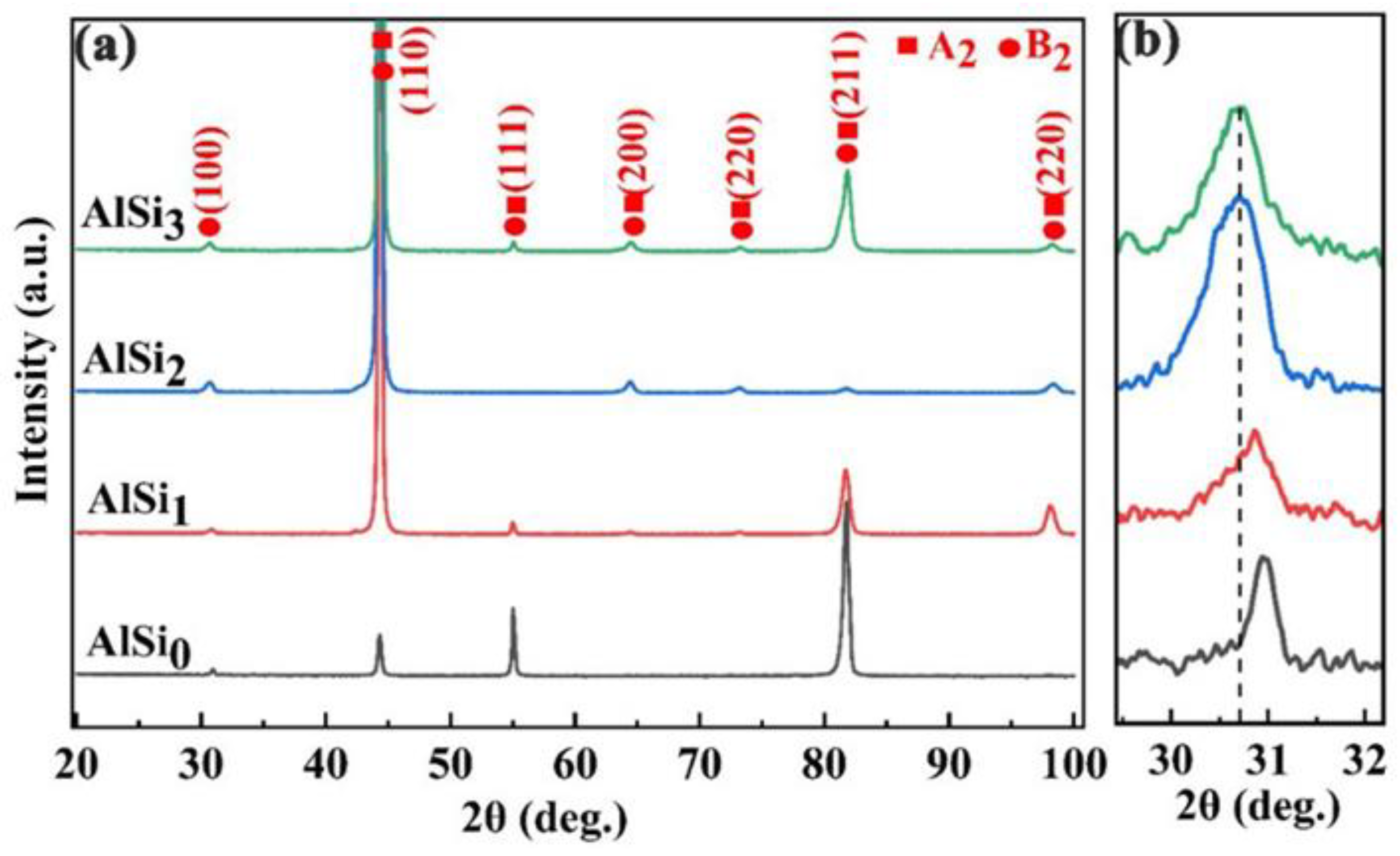
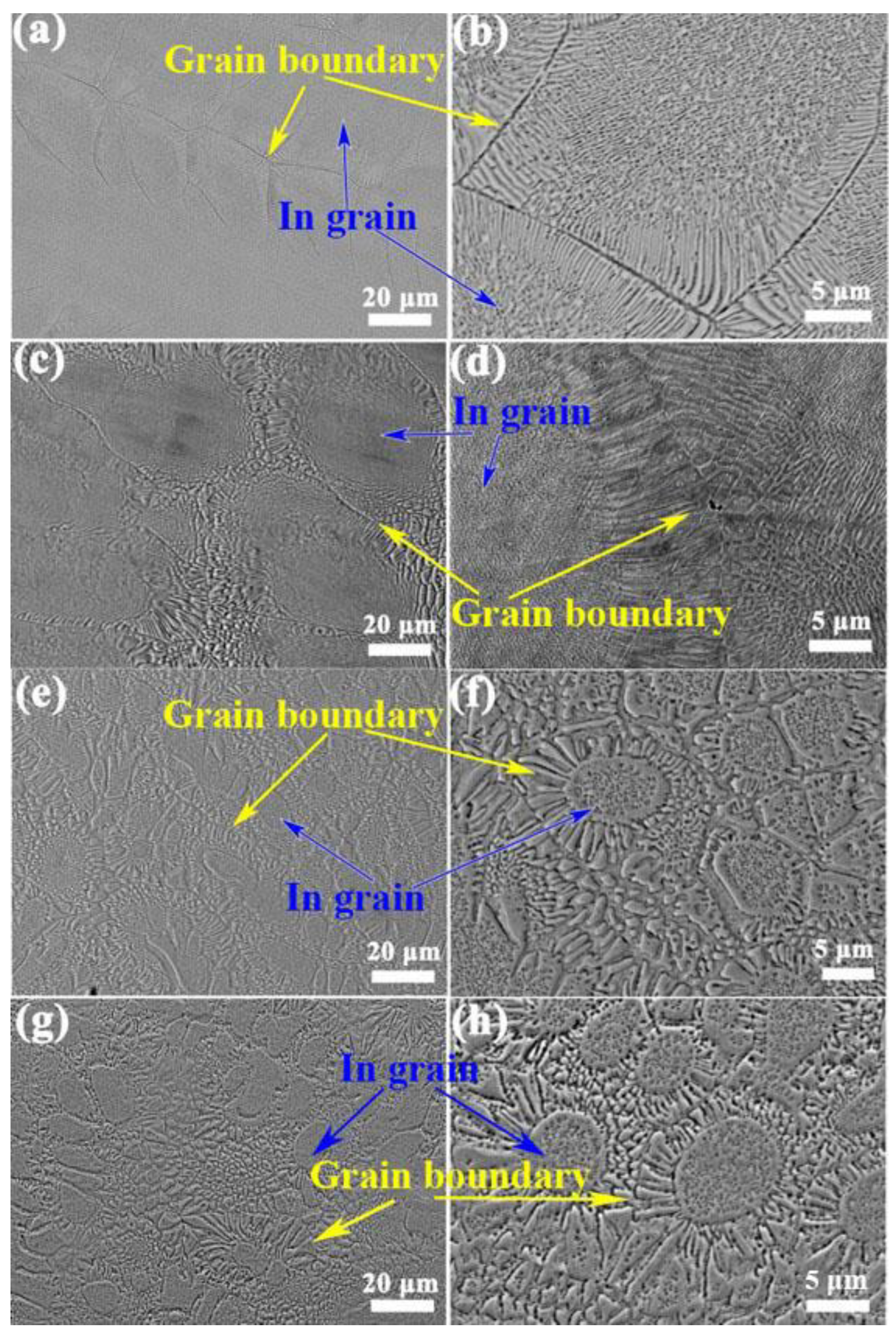
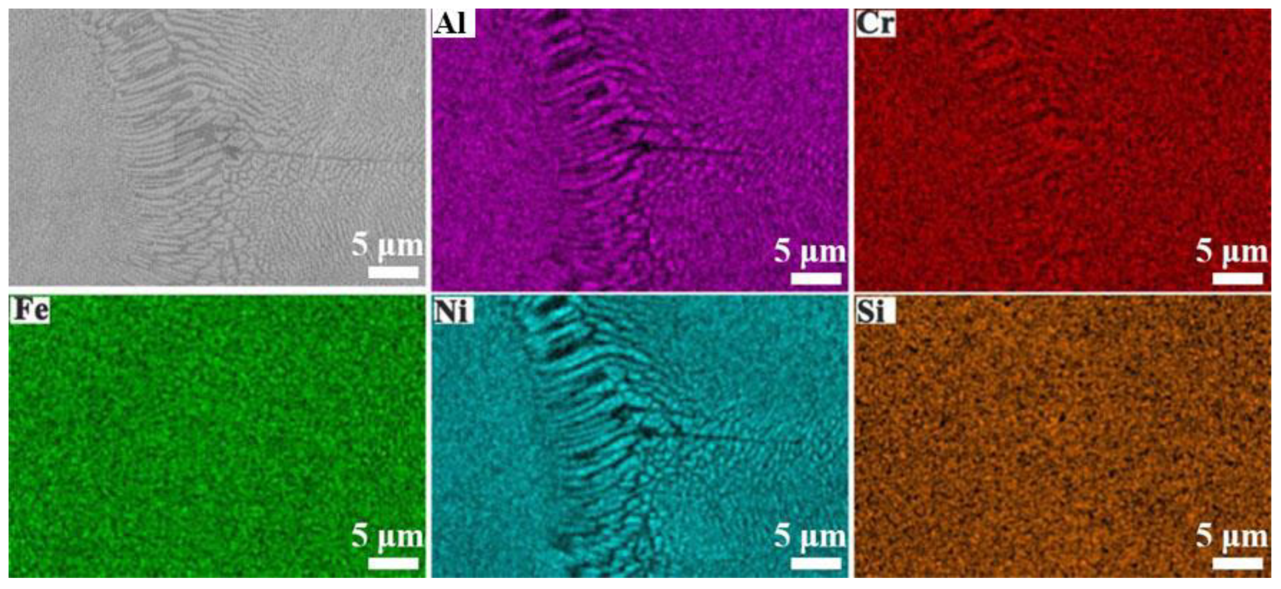
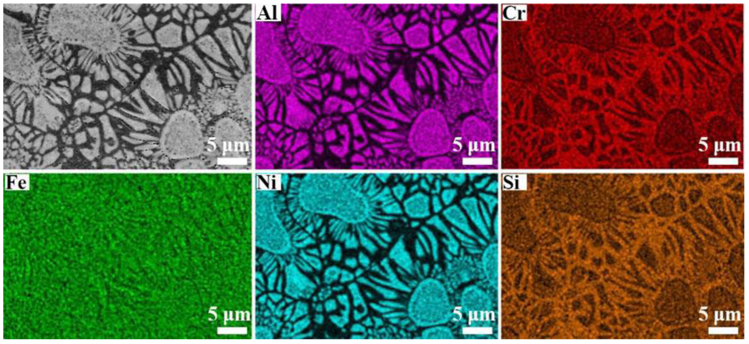
3.1. Phase and Microstructure

Figure 1 shows the XRD patterns of (AlCrFeNi)100-xSix (x = 0, 1, 2, and 3) composite EHEAs with varying Si contents. The results reveal diffraction peaks corresponding to both the B2 and A2 crystal structures in all the alloys. Overlapping peaks are observed in the XRD patterns, suggesting that the ordered Ni-Al (B2) phase and the disordered Fe-Cr (A2) phase have similar crystal structures. According to previous studies, this phenomenon can be attributed to spinodal decomposition [32,33]. The content of B2 phase in the alloy can be characterized by the characteristic peak at (100). As demonstrated in Figure 1b, the intensity of the (100) diffraction peak increases with the addition of Si, while shifting toward smaller angles. This suggests that the large atomic radius mismatch between Si and other elements in the AlCrFeNi HEAs cause lattice distortion, leading to changes in the diffraction angle. Additionally, the increase in the lattice constant of the B2 phase in AlCrFeNi HEAs due to Si addition is also evident. Therefore, the doping of Si increases the B2 phase content in the AlCrFeNi HEAs, indicating that as the Si content increases, the B2 unit cell volume also expands. The lattice parameters and microstrain of the A2 and B2 phases of the AlSi alloy were estimated based on the position of the diffraction peaks, and the results are shown in Table 1.
Figure 2 presents the SEM images of the as-cast (AlCrFeNi)100-xSix (x = 0, 1, 2, 3) composite EHEAs. In Figure 2a, the AlSi0 alloy exhibits a nearly identical lamellar eutectic structure. The high-magnification SEM image of the alloy, shown in Figure 2b, reveals dense lamellae near the grain boundaries. A substantial quantity of rod-shaped lamellar precipitates, distributed uniformly throughout the alloy, is evident. An XRD analysis indicates that these rod-shaped precipitates correspond to the B2 structure, while the matrix consists of BCC phases. Furthermore, it is evident that with an increase in Si content, the lamellar structure at the grain boundaries expands. As shown in Figure 2a,e,g, the grain size of the AlSi2 and AlSi3 alloys is smaller than that of the AlSi0 alloy.
To analyze the distribution of the B2 phase and the Cr-Fe-rich A2 phase in the grains, SEM-EDS surface analyses were conducted on the AlSi1 and AlSi3 alloys. As shown in Figure 3 and Figure 4, the lamellar composite structure at the grain boundaries consists of alternating layers of the B2 phase enriched in Al-Ni and the A2 phase enriched in Cr-Fe. In the flower disk structure of Figure 4, there are particle-like Cr-Ni-rich phases surrounded by Al-Ni-rich phases. Comparing the grains in Figure 3 and Figure 4, it can be observed that with increasing Si content, the B2 lamellar structure enlarges as the grain boundary regions expand, which is consistent with the shift in the (100) diffraction peak of the B2 phase to smaller angles. In the AlSi1 alloy, the distribution of elements at the grain boundaries is uniform, with no distinct B2 or A2 phases. In the AlSi3 alloy, a well-defined alternation of the A2 and B2 phases is observed in both the grains and the grain boundaries. The central particles and the petal-shaped lamellae radiating outward from the center are Cr-Fe-rich A2 phases, while the other parts of the center and the non-radiating lamellae are B2 phases. Moreover, the volume fraction of lamellar structures at the grain boundaries increases, leading to an overall increase in the grain boundary regions with higher Si content. This corresponds to an increase in the B2 phase content, which aligns with the XRD phase analysis results.
The Si element is primarily distributed around the B2 particles at the grain boundaries. Therefore, the addition of Si in AlCrFeNi HEAs promotes precipitation of the B2 phase at these boundaries, which is consistent with the increase in the intensity of the (100) diffraction peak. The expansion of the lamellar composite structure at the grain boundaries, along with the reduction in grain size and its tendency to become more rounded, ultimately leads to the formation of a sunflower-like composite structure (as shown in Figure 2f,h). The petal-like lamellar composite structure radiates outward from the central disc region, while sunflower-seed-like precipitates are uniformly distributed within the central disc. According to the literature, the formation of such structures can be attributed to the spinodal decomposition process [32,33], where the A2 and B2 phases grow in a lamellar form from the boundaries perpendicular to the previously precipitated phase after grain formation.
To further analyze and identify the microstructure, phase composition, and element distribution of the alloy, a TEM analysis was performed on the AlSi3 alloy as an example. Figure 5 shows the TEM images of the sunflower structure in the AlSi3 alloy and the corresponding selected area electron diffraction (SAED) patterns. Figure 5a presents a low-magnification TEM bright-field image, revealing that the alloy structure consists of two regions: the sunflower-like disk and petal regions. Figure 5b shows a high-angle annular dark-field (HAADF) TEM image at the boundary between the sunflower disk and petal regions. The alternating light and dark bands in the petal region indicate that adjacent lamellae have different phase structures. A considerable quantity of submicron-sized sunflower seed-like particles are precipitated in the sunflower disk region. Figure 5c shows a high-magnification image of rod-shaped precipitates in the petal region, showing a significant number of nanoscale precipitates of the B2 phase on the A2 phase lamellae. Figure 5d is a high-magnification TEM image of the petal region, and Figure 5e–h present the SAED patterns along the crystal zone axis. In Figure 5a, the light gray region in the sunflower disk separates all the elliptical grains. The enlarged view in Figure 5b shows that the disk region contains spherical or elliptical-shaped precipitates, while the rod-shaped precipitates in the petal region alternate. Figure 5d provides an enlarged view of the rod-shaped precipitates in the petal region. A diffraction analysis confirms that the grains in the sunflower disk region correspond to the A2 phases (Figure 5e), while the rest are characterized by the B2 phases (Figure 5f). The compositions of adjacent rod-shaped precipitates in the petal region differ, with the diffraction spots in Figure 5g,h showing that these rod-shaped precipitates are the B2 and A2 phases, respectively.
The TEM-EDS elemental analysis was conducted on the region shown in Figure 5b, and the resulting elemental distribution map is presented in Figure 6. The analysis reveals that the two phases are enriched in different elements: the bright A2 phase is rich in Fe and Cr, while the darker B2 phase is primarily composed of Ni and Al. Both phases contain Si, but the Si content is notably higher in the B2 phase than in the A2 phase.

3.2. Mechanical Properties

3.2.1. Compression Properties and Vickers Hardness of (AlCrFeNi)100-xSix Composite EHEAs

Figure 7a shows the compression stress–strain curves for the as-cast (AlCrFeNi)100-xSix composite EHEAs with varying Si content. As illustrated, compared to the AlSi0 alloy, the other three alloys exhibit minimal changes in plasticity and toughness but show a significant increase in yield strength (YS). Notably, the YS of the AlSi3 alloy reaches 1360 MPa.
Figure 7b illustrates the variation in Vickers hardness (HV) and YS (σy) with respect to the Si content (x) in the as-cast (AlCrFeNi)100-xSix composite EHEAs. It is evident that both HV and YS follow a similar increasing trend with increasing Si content. From the AlSi0 to AlSi3 alloys, HV and YS show a steady rise. Specifically, there is a sharp increase from AlSi0 to AlSi1, a moderate increase from AlSi1 to AlSi2, and a more pronounced increase from AlSi2 to AlSi3. These four alloys can be divided into two groups: one group includes AlSi0 and AlSi1, while the other consists of AlSi2 and AlSi3. The most salient structural characteristic of the latter group is the presence of a substantial quantity of sunflower composite eutectic structures. This suggests that the addition of an appropriate amount of Si in the (AlCrFeNi)100-xSix composite EHEAs system promotes the formation of sunflower composite structures, which significantly enhance the mechanical properties. Previous studies on sunflower composite structures have also indicated their positive effect on improving the compressive properties of alloys [34].
Table 2 summarizes the mechanical properties of the four alloys. The compression test results show that the YS of the AlSi0, AlSi1, AlSi2, and AlSi3 alloys are 1131 MPa, 1241 MPa, 1272 MPa, and 1360 MPa, respectively. The alloys fracture strengths are 3135 MPa, 3259 MPa, 3261 MPa, and 3019 MPa, with corresponding fracture strain values of 35.6%, 33.3%, 33.8%, and 34.3%, respectively. The HV values of these four alloys range from 445 HV to 469 HV (445 HV, 460 HV, 461 HV, and 469 HV, respectively). Overall, the AlSi3 alloy exhibits superior mechanical properties.

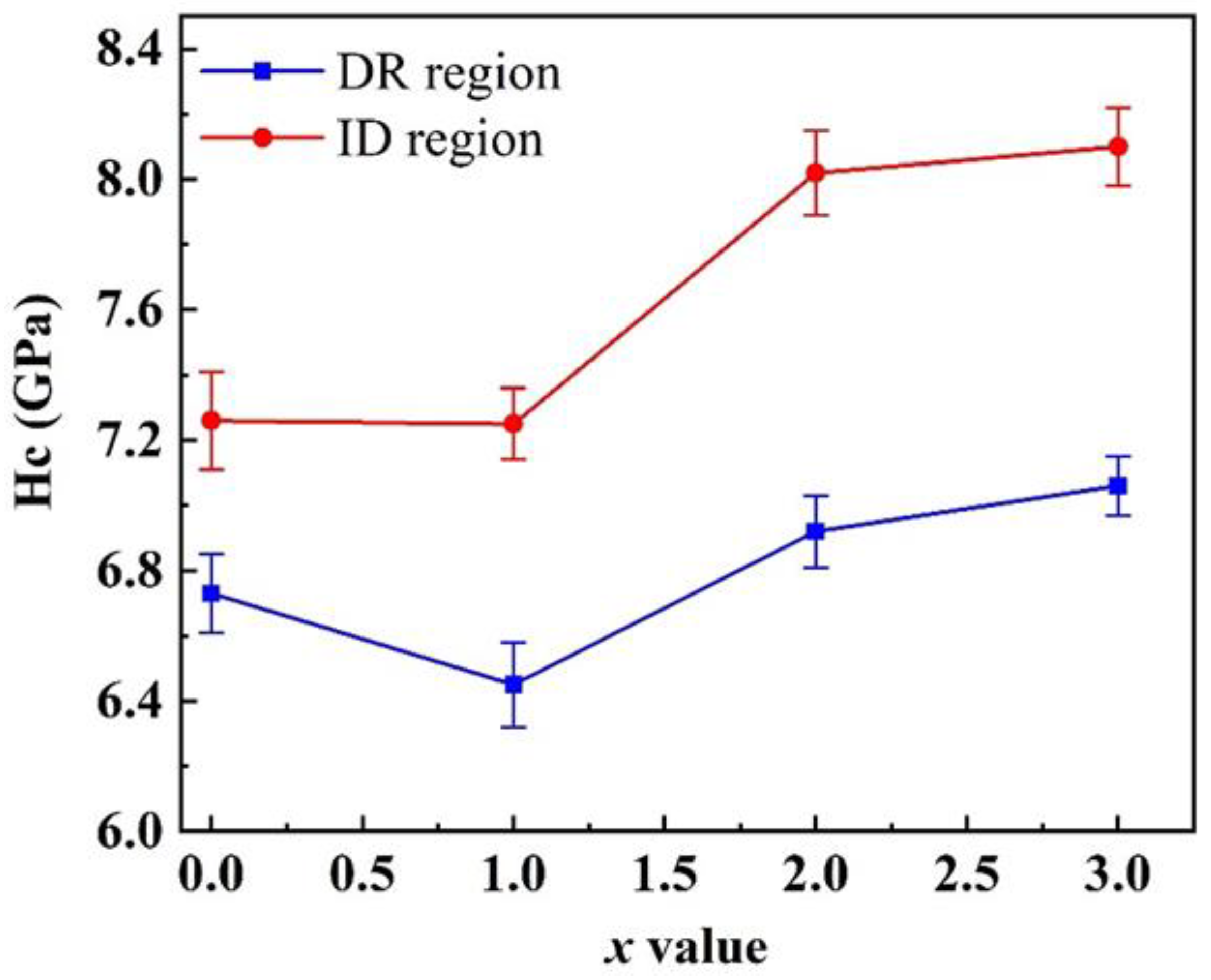
3.2.2. Nanoindentation Testing of (AlCrFeNi)100-xSix Composite EHEAs

To further investigate the micro-mechanical properties of different regions in the as-cast (AlCrFeNi)100-xSix composite EHEAs, nanoindentation tests were performed on both the grain boundary (petal) and the grain interior (flower disk) of each alloy. To ensure accuracy, 20 indents were made in each phase, and the average value was taken as the nano-hardness for that phase. The results of these tests are shown in Figure 8 and Table 3. Figure 8a,b show typical nanoindentation load–displacement curves for the grain interior and grain boundary regions of the as-cast (AlCrFeNi)100-xSix (x = 0, 1, 2, 3) composite EHEAs. It is clear that the hardness values of the grain interior and grain boundary regions of the AlSi3 alloy are the highest, measuring 7.06 GPa and 8.10 GPa, respectively. The hardness values of the AlSi2 alloy are close to those of AlSi3, with hardness values of 8.02 GPa and 6.92 GPa at the grain boundary and grain interior, respectively. The hardness values at the grain boundary of AlSi0 and AlSi1 alloys are nearly identical, at 7.26 GPa and 7.25 GPa, whereas their hardness values in the grain interior are 6.73 GPa and 6.45 GPa, respectively. Figure 8c shows the atomic force microscope (AFM) image used to identify suitable locations for indentation on the alloy surface, in conjunction with the nano-indenter. The positions of the sunflower disk and petal regions were determined from the AFM image for indentation testing.
Figure 9 shows the trend of hardness values in the grain interior and grain boundary regions of the experimental alloys as a function of Si content. The results indicate that the hardness in the grain boundary regions is higher than in the grain interior regions for all four alloys. This can be attributed to the addition of Si, which causes a significant amount of lamellar B2 phase precipitation at the grain boundaries, thereby enhancing hardness through a precipitation strengthening effect. Additionally, Figure 9 indicates a significant increase in hardness for both regions when x = 2. This substantial hardness increase occurs just after the formation of the sunflower composite structure. The sunflower composite structure refines the microstructure of the alloy, leading to higher hardness values for the AlSi2 and AlSi3 alloys compared to AlSi0 and AlSi1.

3.3. Strengthening Mechanisms of (AlCrFeNi)100-xSix Composite EHEAs

It is assumed here that precipitation strengthening induced by uniformly distributed, ordered B2 precipitate phases enhances the YS of as-cast (AlCrFeNi)100-xSix composite EHEAs. Previous studies have shown [35,36] that precipitation strengthening of the solid-solution matrix can occur through either the Orowan dispersion mechanism or the dislocation shear mechanism, with the effectiveness of the Orowan mechanism relying on the interaction between moving dislocations and the precipitate phase. Typically, the dominance of the shear mechanism and the Orowan mechanism is governed by the size of the precipitates and their compatibility with the matrix, respectively [37]. In AlSi2 and AlSi3 alloys with graded B2 precipitates embedded in an A2 matrix, the shear mechanism prevails in the nanoscale B2 precipitates, while the Orowan dispersion mechanism dominates in the submicron B2 precipitates.
The enhancement in YS from the precipitation shear mechanism in nanoscale precipitates is attributed to three factors: coherency strengthening (ΔσCS), modulus strengthening (ΔσMS), and ordering strengthening (ΔσOS). The classical equations for calculating their contributions are given in [36,38]:
Δ σ CS = M α ε G ε c 3 2 rf 0.5 Gb 1 2
Δ σ MS = 0.0055 M Δ G 3 2 r b 3 m 2 - 1
Δ σ OS = 0.81 M γ apb 2 b 3 π f 8 1 2
In the equation, M = 2.73 (M is the Taylor factor [36]). αε = 2.6 [39]. εc is the lattice misfit under constraint, defined as εc = 2ε/3. The expression ε = ∆α/α = 0.0038 is utilized to represent the misfit between the matrix and the precipitate phase [40]. b is the magnitude of the Burgers vector, which is expressed as 3α/2. R denotes the average radius of the nanoscale B2 precipitates, measured at 11 nm. F represents the volume fraction of the nanoscale precipitates [41], which is 15.8%. The shear modulus G (using α-Fe) is 83 GPa, while ΔG denotes the shear modulus mismatch between the A2 matrix and the B2 precipitates, valued at 3 GPa (for the B2-NiAl phase, G = 80 GPa) [42]. It has been established that the constant for edge dislocations is m = 0.85 [43]. The anti-phase boundary energy for the B2 phase is represented by γapb, which is equivalent to 0.25 J/m−2 [44]. It is important to note that these strengthening processes are sequential, with the first two factors (ΔσCS and ΔσMS) acting before dislocation shear of the precipitates, while the last factor (ΔσOS) contributes during the shear process. In this case, the overall strength increase from the shear mechanism is determined by the sum of (ΔσCS + ΔσMS) or ΔσOS. The strength increases from (ΔσCS + ΔσMS) in the A2 matrix due to the 22 nm B2 nano-dispersions were found to be ΔσCS = 487 MPa, ΔσMS = 100.9 MPa, and ΔσOS = 276.3 MPa. The total shear mechanism strength increase is thus 587.9 MPa.
When the particles are large or incoherent with the matrix, the Orowan dispersion mechanism becomes dominant. The Orowan-type mechanism (ΔσOrowan) can be calculated using the following equation [45]:
Δ σ Orowan = 0.4 MGb ln ( 2 2 r 3 / b ) λ P π 1 - ν
In this equation, ν is the Poisson’s ratio of the BCC metal, with a value of 0.3, where r = 208 n, f = 26.5%, and λP denotes the precipitation spacing of the submicron-sized precipitates, defined as follows:
λ P = 2 2 3 r π 4 f - 1
By incorporating these values into the above equation, the YS increase induced by the submicron B2 precipitates was obtained, with ΔσOrowan = 263.5 MPa.
On this basis, the strengthening due to precipitate hardening is estimated to be approximately 851.4 MPa, and the true YS of the as-cast AlSi2 alloy (~1272 MPa) is primarily attributed to approximately 66.93%. With precipitation strengthening, the remaining strength is mainly attributed to mechanisms such as the lattice friction strength of the A2 matrix, solid-solution strengthening, and grain boundary strengthening. The analysis reveals that shear mechanism strengthening contributes a stress increment of about 440.8 MPa, while Orowan dispersion strengthening contributes a stress increment of 518.1 MPa.

4. Conclusions

This paper prepared cast ingots of (AlCrFeNi)100-xSix (x = 0, 1, 2, 3) composite EHEAs, with varying Si contents and systematically investigated the effect of Si doping on the microstructure and mechanical properties of AlCrFeNi-based composite EHEAs. The following conclusions were drawn:
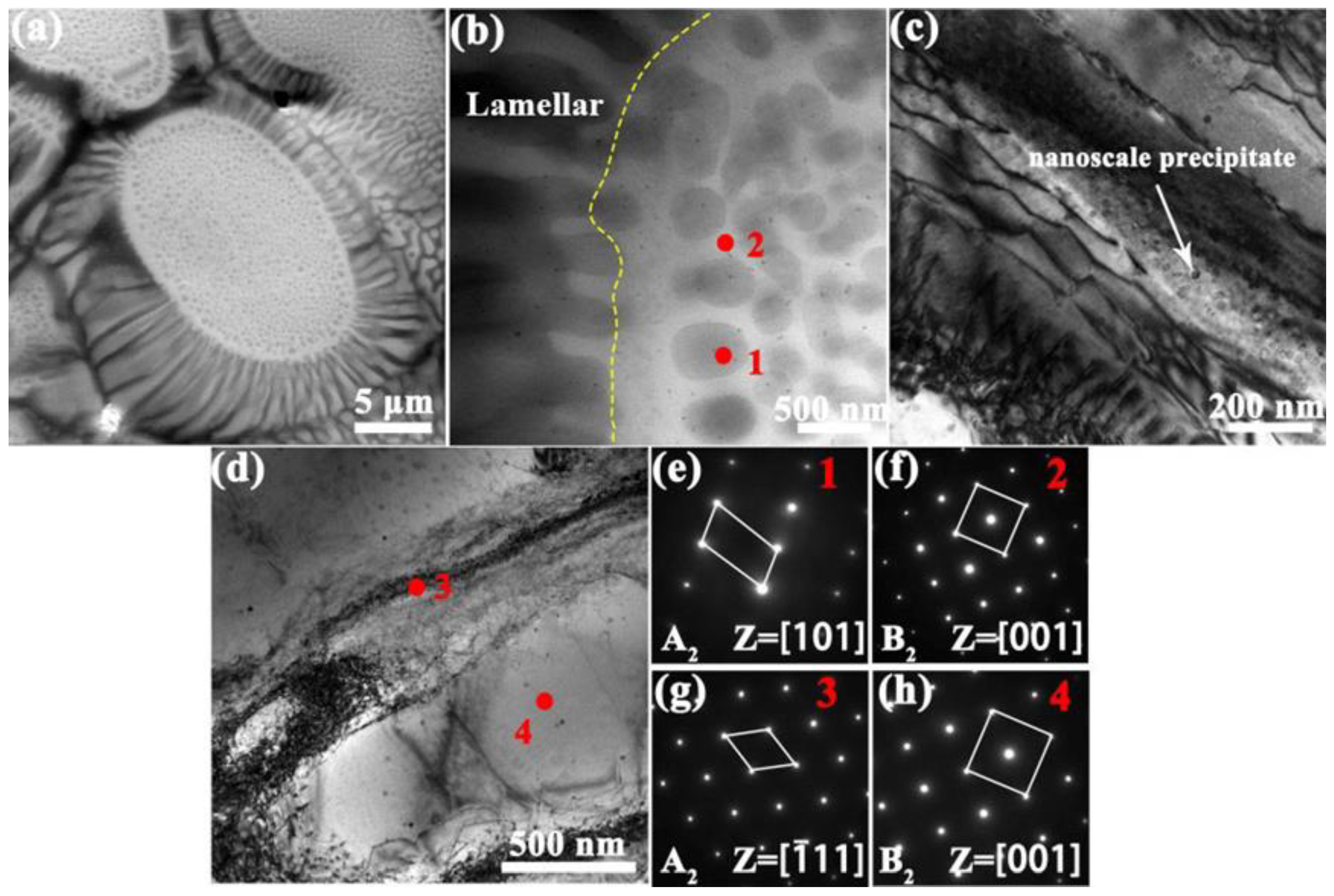
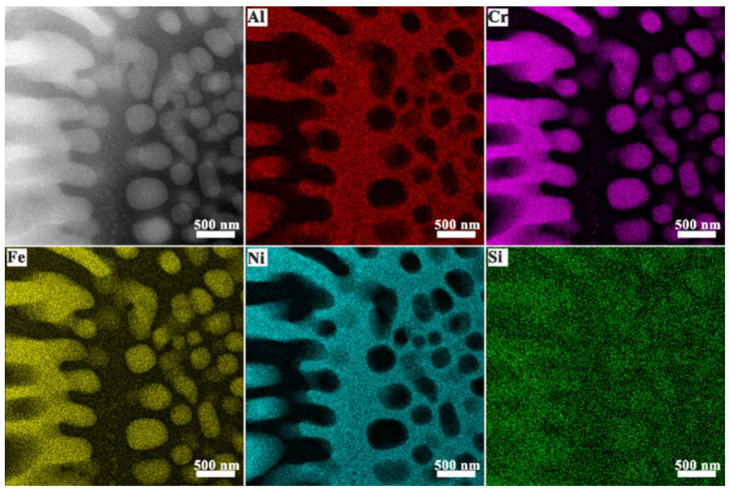
  • The microstructure of (AlCrFeNi)100-xSix (x = 0, 1, 2, 3) composite EHEAs consists of two regions: the grain interior (flower disk) and grain boundaries (flower petals). The grain interior exhibits an alternating A2/B2 lamellar composite structure with B2 phase nano-dispersed precipitates. As the Si content increases, the lamellar structure at the grain boundaries expands, forming flower petals, while the precipitates within the alloys evolve into flower disks and the alloy exhibits a sunflower-like composite structure. The volume fraction of lamellar structures increases in the petals, accompanied by grain refinement.
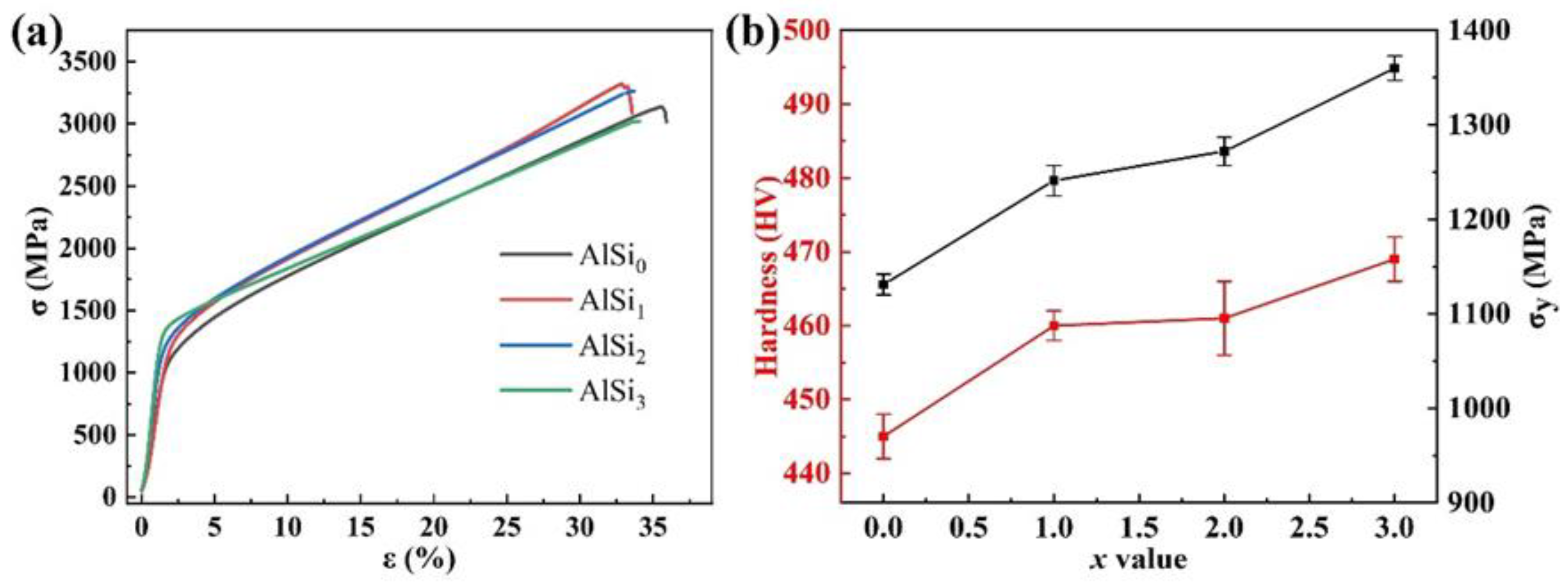
  • With increasing Si content, the yield strength of the alloy increases from 1131 MPa for the AlSi0 alloy to 1360 MPa for the AlSi3 alloy. The shear strengthening mechanism caused by nano-precipitates and the Orowan dispersion strengthening caused by sub-micron precipitates contribute approximately 587.9 MPa and 267.5 MPa, respectively.
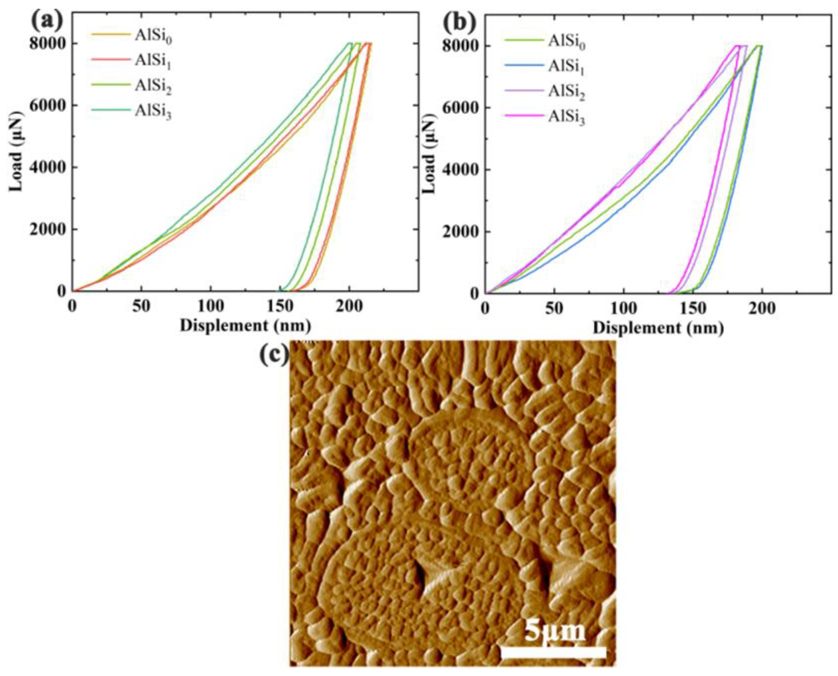
  • A significant number of nano/sub-micron precipitates on lamellar structures at grain boundaries enhance precipitation strengthening, resulting in greater hardness at the grain boundaries compared to the grain interiors in (AlCrFeNi)100-xSix (x = 0, 1, 2, 3) composite EHEAs. The formation of the sunflower-like composite structure refines the alloy’s microstructure, leading to higher hardness in AlSi2 and AlSi3 alloys compared to the AlSi0 and AlSi1 alloys.

Author Contributions

Conceptualization, Y.J., B.Z. and Y.L.; Methodology, S.L., A.L., K.K., J.Z., D.H., C.C., Y.J. and M.X.; Software, D.H., C.C., Y.J., M.X., B.Z. and Y.L.; Formal analysis, S.L., A.L. and J.Z.; Investigation, S.L. and A.L.; Resources, G.L.; Writing—original draft, S.L.; Writing—review and editing, G.L.; Supervision, K.K.; Funding acquisition, G.L. All authors have read and agreed to the published version of the manuscript.

Funding

This research was funded by National Key Research and Development Program of China (grant number 2022YFA1603800), National Natural Science-Foundation of China (grant number 12274362), and Songshan Lake Materials Laboratory (grant number 2022SLABFK01).

Data Availability Statement

The original contributions presented in this study are included in this article. Further inquiries can be directed to the corresponding author.

Conflicts of Interest

The authors declare no conflicts of interest.

References

  1. Wu, Y.; Liaw, P.K.; Li, R.; Zhang, W.; Geng, G.; Yan, X.; Liu, G.; Zhang, Y. Relationship between the unique microstructures and behaviors of high-entropy alloys. Int. J. Miner. Metall. Mater. 2024, 31, 1350–1363. [Google Scholar] [CrossRef]
  2. Yadav, Y.K.; Shaz, M.A.; Mukhopadhyay, N.K.; Yadav, T.P. Formation of B2 phase and its stability in equiatomic Al-Cu-Fe-Ni-Ti high entropy alloy. J. Alloys Metall. Syst. 2024, 8, 100137. [Google Scholar] [CrossRef]
  3. Rao, K.R.; Mohan, M.; Dewangan, S.K.; Nagarjuna, C.; Lee, K.; Ahn, B. Microstructural characterization and thermal stability of AlCrFeNiTi + Y2O3 high-entropy alloy nanocomposites prepared by mechanical alloying. Mater. Lett. 2024, 372, 137018. [Google Scholar]
  4. Kotan, H.; Koç, R.C.; Batıbay, A.B. Remarkable thermal stability of nanocrystalline CoCrFeNi high entropy alloy achieved through the incorporation of rare-earth element samarium. Intermetallics 2025, 178, 108608. [Google Scholar] [CrossRef]
  5. Zhang, J.; Yoon, K.N.; Kim, M.S.; Ahn, H.S.; Kim, J.Y.; Ryu, W.H.; Park, E.S. Manipulation of Microstructure and Mechanical Properties in N-Doped CoCrFeMnNi High-Entropy Alloys. Metals 2021, 11, 1487. [Google Scholar] [CrossRef]
  6. Kovalenko, E.; Krasanov, I.; Valdaytseva, E.; Stankevich, S.; Klimova-Korsmik, O.; Gushchina, M. Microstructure and Mechanical Properties of High-Entropy Alloy FeCoNiCr(X) Produced by Laser Directed Energy Deposition Process: Effect of Compositional Changes. Metals 2024, 15, 26. [Google Scholar] [CrossRef]
  7. Pourmohammadi, S.; Mohammadnejad, A.; Bahrami, A.; Anijdan, S.H.M.; Park, N.; Ghosh, M.; Stability, P. Microstructure, and Mechanical Properties of Spark Plasma Sintered Nanocrystalline Boron-Doped AlCoFeMnNi High-Entropy Alloy. Metals 2023, 13, 1025. [Google Scholar] [CrossRef]
  8. Jiang, B.; Huang, Z.; Liu, C.; Wang, H.; Shu, F.; Zhao, Y.; Lei, H. Optimization of Process Parameters and Microstructure of CoCrFeNiTiAl High-Performance High-Entropy Alloy Coating. Metals 2024, 14, 1384. [Google Scholar] [CrossRef]
  9. Zhang, H.; Zhang, G.-H. Preparation and performances of molybdenum—Copper alloy with additions of tungsten, nickel, iron and cerium dioxide. Int. J. Refract. Met. Hard Mater. 2024, 121, 106691. [Google Scholar] [CrossRef]
  10. Pan, Y.; Li, B.; Xu, Y.; Wu, D.; Hou, X.; Gao, Y.; Bai, P.; Liang, C. Effect of Sigma and L21 phases co-precipitation on the mechanical properties of CoCr0.6NiV0.6Al0.35Tix high entropy alloy. Mater. Sci. Eng. A 2025, 923, 147689. [Google Scholar] [CrossRef]
  11. Tan, M.; Meng, L.; Lin, C.; Ke, L.; Liu, Y.; Qu, J.; Qi, T. Variation of microstructures and properties of Co0.2CrAlNi high entropy alloy doped Si. J. Alloys Compd. 2022, 927, 167081. [Google Scholar] [CrossRef]
  12. Huang, L.; Wang, X.; Jia, F.; Zhao, X.; Huang, B.; Ma, J.; Wang, C. Effect of Si element on phase transformation and mechanical properties for FeCoCrNiSix high entropy alloys. Mater. Lett. 2021, 282, 128809. [Google Scholar] [CrossRef]
  13. Liao, L.; Cheng, Y.; Dai, S.; Khan, M.A.; Zhang, H.; Li, F. Effect of cold-rolling and annealing temperature on microstructure, texture evolution and mechanical properties of FeCoCrNiMn high-entropy alloy. J. Mater. Res. Technol. 2024, 33, 683–697. [Google Scholar] [CrossRef]
  14. Odabas, O.; Ozgurluk, Y.; Karaoglanli, A.C. Microstructural evolution and high temperature hot corrosion behaviour of AlCoCrFeNiTi high-entropy alloy coatings. Mater. Today Commun. 2024, 41, 110910. [Google Scholar] [CrossRef]
  15. Yi, H.; Zhang, Y.; Xie, R.; Bi, M.; Wei, D. High-Temperature Deformation Behaviors of the C-Doped and N-Doped High Entropy Alloys. Metals 2021, 11, 1517. [Google Scholar] [CrossRef]
  16. Liu, D.; Jin, X.; Yang, H.; Qiao, J.; Zhang, Y. High-Temperature Mechanical Behavior of Cobalt-Free FeMnCrNi(Al) High-Entropy Alloys. Metals 2023, 13, 1885. [Google Scholar] [CrossRef]
  17. Wang, Y.; Li, D.; Wang, S.; Zhang, M.; Gong, P.; Hu, Z.; Li, B. Effect of Cr content on the high temperature oxidation behavior of FeCoNiMnCr porous high-entropy alloys. J. Mater. Res. Technol. 2024, 33, 3324–3333. [Google Scholar] [CrossRef]
  18. Wang, M.; Lu, Y.; Lan, J.; Wang, T.; Zhang, C.; Cao, Z.; Li, T.; Liaw, P.K. Lightweight, ultrastrong and high thermal-stable eutectic high-entropy alloys for elevated-temperature applications. Acta Mater. 2023, 248, 118806. [Google Scholar] [CrossRef]
  19. Wang, M.; Lu, Y.; Wang, T.; Zhang, C.; Cao, Z.; Li, T.; Liaw, P.K. A novel bulk eutectic high-entropy alloy with outstanding as-cast specific yield strengths at elevated temperatures. Scr. Mater. 2021, 204, 114132. [Google Scholar] [CrossRef]
  20. Samoilova, O.; Pratskova, S.; Suleymanova, I.; Shaburova, N.; Moghaddam, A.O.; Trofimov, E. Effect of Pt Addition on the Oxidation and Corrosion Resistance of Al0.25CoCrFeNi High-Entropy Alloy. Metals 2023, 13, 1709. [Google Scholar] [CrossRef]
  21. Qi, W.; Wang, W.; Yang, X.; Xie, L.; Zhang, J.; Li, D.; Zhang, Y. Effect of Zr on phase separation, mechanical and corrosion behavior of heterogeneous CoCrFeNiZrx high-entropy alloy. J. Mater. Sci. Technol. 2022, 109, 76–85. [Google Scholar] [CrossRef]
  22. Zhou, Y.; Liu, X.; Chen, J.; Wang, A.; Fu, H.; Zhang, H.; Zhu, Z. Strategies for optimizing mechanical properties of refractory high entropy alloys induced by solid solution strengthening mechanism. Mater. Sci. Eng. A 2025, 923, 147696. [Google Scholar] [CrossRef]
  23. Ye, X.; Diao, Z.; Lei, H.; Wang, L.; Li, Z.; Li, B.; Feng, J.; Chen, J.; Liu, X.; Fang, D. Multi-phase FCC-based composite eutectic high entropy alloy with multi-scale microstructure. Mater. Sci. Eng. A 2024, 889, 145815. [Google Scholar] [CrossRef]
  24. Chen, Y.; Tang, C.; Jiang, J.-Z. Bulk metallic glass composites containing B2 phase. Prog. Mater. Sci. 2021, 121, 100799. [Google Scholar] [CrossRef]
  25. Aizenshtein, M.; Strumza, E.; Brosh, E.; Hayun, S. Precipitation kinetics, microstructure, and equilibrium state of A2 and B2 phases in multicomponent Al2.75CoCrFeNi alloy. J. Mater. Sci. 2020, 55, 7016–7028. [Google Scholar] [CrossRef]
  26. Aizenshtein, M.; Hayun, S. Synthesis of A2 and B2 phases in AlxCoCrFeNi multi-component system. Metallogr. Microstruct. Anal. 2020, 9, 305–311. [Google Scholar] [CrossRef]
  27. Callegari, B.; Lima, T.N.; Coelho, R.S. The influence of alloying elements on the microstructure and properties of Al-Si-based casting alloys: A review. Metals 2023, 13, 1174. [Google Scholar] [CrossRef]
  28. Gu, X.; Zhuang, Y.-X.; Jia, P. Evolution of the microstructure and mechanical properties of as-cast Al0.3CoCrFeNi high entropy alloys by adding Si content. Mater. Sci. Eng. A 2022, 840, 142983. [Google Scholar] [CrossRef]
  29. Yang, H.; Liu, X.; Li, A.; Li, R.; Xu, S.; Zhang, M.; Yu, P.; Yu, S.; Jiang, M.; Huo, C.; et al. Effect of silicon addition on the corrosion resistance of Al0.2CoCrFe1.5Ni high-entropy alloy in saline solution. J. Alloys Compd. 2023, 964, 171226. [Google Scholar] [CrossRef]
  30. Luo, W.; Yuan, X.; Zhang, Z.; Cheng, C.; Liu, H.; Qiu, H.; Cheng, X. Effect of volumetric energy density on the mechanical properties and corrosion resistance of laser-additive-manufactured AlCoCrFeNi2.1 high-entropy alloys. J. Alloys Compd. 2025, 1010, 178032. [Google Scholar] [CrossRef]
  31. Erdogan, A.; Sunbul, S.E.; Icin, K.; Doleker, K.M. Microstructure, wear and oxidation behavior of AlCrFeNiX (X= Cu, Si, Co) high entropy alloys produced by powder metallurgy. Vacuum 2021, 187, 110143. [Google Scholar] [CrossRef]
  32. Yang, T.; Deng, H.; Wang, Y.; Feng, J.; Meng, Q.; Qi, J.; Wei, F.; Hu, Z.; Meng, D.; Sui, Y. Study on the Microstructure and Mechanical Properties of AlCr1.6FexNi(3.2-X)Si0.2 High-Entropy Alloys. SSRN 2024, 4705447. [Google Scholar] [CrossRef]
  33. Yue, K.; Yang, X.; Wang, L.; Su, L.; Xu, Q.; Xu, Z.; Cheng, C.; Wang, Y.; Wang, Z.; Chen, Z. Effect of Ti content on spinodal decomposed microstructure and properties of AlCoCrFeNiTix high-entropy alloy coatings prepared by laser cladding. J. Mater. Res. Technol. 2025, 34, 1120–1129. [Google Scholar] [CrossRef]
  34. Li, S.; Lv, J.; Xu, K.; Lou, M.; Hu, X.; Xiao, X.; Liu, S.; Chang, K. Manipulation of the spinodal decomposition behavior in a multicomponent system. Scr. Mater. 2022, 219, 114893. [Google Scholar] [CrossRef]
  35. Wei, X.; Zhang, L.; Zhang, C.; Li, G. A sunflower-like eutectic microstructure in the AlCrFeMnNi2 high-entropy alloy with excellent compressive mechanical properties. Mater. Lett. 2023, 339, 134107. [Google Scholar] [CrossRef]
  36. Ma, Y.; Wang, Q.; Jiang, B.B.; Li, C.L.; Hao, J.M.; Li, X.N.; Dong, C.; Nieh, T.G. Controlled formation of coherent cuboidal nanoprecipitates in body-centered cubic high-entropy alloys based on Al2(Ni,Co,Fe,Cr)14 compositions. Acta Mater. 2018, 147, 213–225. [Google Scholar] [CrossRef]
  37. Seidman, D.N.; Marquis, E.A.; Dunand, D.C. Precipitation strengthening at ambient and elevated temperatures of heat-treatable Al (Sc) alloys. Acta Mater. 2002, 50, 4021–4035. [Google Scholar] [CrossRef]
  38. Nembach, E. Precipitation hardening caused by a difference in shear modulus between particle and matrix. Phys. Status Solidi (A) 1983, 78, 571–581. [Google Scholar] [CrossRef]
  39. Jansson, B.; Melander, A. On the critical resolved shear stress from misfitting particles. Scr. Metall. 1978, 12, 497–498. [Google Scholar] [CrossRef]
  40. Courtney, T.H. Mechanical Behavior of Materials; Waveland Press: Long Grove, IL, USA, 2005. [Google Scholar]
  41. Hudok, D. Properties and Selection: Irons, Steels, and High-Performance Alloys; Metals Handbook; ASM Press: Washington, DC, USA, 1990; Volume 1, pp. 200–211. [Google Scholar]
  42. Wasilewski, R. Elastic constants and youngs modulus of NiAl. AIME Met Soc. Trans. 1966, 236, 455–457. [Google Scholar]
  43. Melander, A.; Persson, P.Å. The strength of a precipitation hardened AlZnMg alloy. Acta Metall. 1978, 26, 267–278. [Google Scholar] [CrossRef]
  44. Hong, T.; Freeman, A. Effect of antiphase boundaries on the electronic structure and bonding character of intermetallic systems: NiAl. Phys. Rev. B 1991, 43, 6446. [Google Scholar] [CrossRef]
  45. Martin, J.W. Particle strengthening of metals and alloys. Mater. Sci. Technol. 1997, 13, 705. [Google Scholar]
Figure 1. The as-cast (AlCrFeNi)100-xSix composite EHEAs. (a) XRD patterns, (b) magnified view of the (100) diffraction peak.
Metals 15 00207 g001
Figure 2. SEM images of the as-cast (AlCrFeNi)100-xSix composite EHEAs. (a,b) AlSi0, (c,d) AlSi1, (e,f) AlSi2, (g,h) AlSi3.
Metals 15 00207 g002
Figure 3. SEM images and EDS elemental maps of the as-cast AlSi1 alloy.
Metals 15 00207 g003
Figure 4. SEM images and EDS elemental maps of the as-cast AlSi3 alloy.
Metals 15 00207 g004
Figure 5. TEM images of the as-cast AlSi3 alloy: (a) low-magnification image, (b) high-magnification image of the boundary between the flower disk and petal regions, (c) high-magnification image of the nanometer-sized precipitates within the rod-shaped precipitates in the petal region, (d) high-magnification image of the boundary of the rod-shaped precipitates in the petal region, (eh) SAED patterns from the corresponding regions.
Metals 15 00207 g005
Figure 6. HAADF image and EDS elemental maps of the as-cast AlSi3 alloy.
Metals 15 00207 g006
Figure 7. (a) Compression curves of the as-cast (AlCrFeNi)100-xSix composite EHEAs, (b) variation trends of hardness (HV) and YS (σy) as a function of the Si content (x).
Metals 15 00207 g007
Figure 8. Nanoindentation load–displacement curves of the as-cast (AlCrFeNi)100-xSix (x = 0, 1, 2, 3) composite EHEAs for (a) the DR region and (b) the ID region. (c) Atomic force microscopy image showing the selected indentation points in the flower disk and petal regions.
Metals 15 00207 g008
Figure 9. Line graph showing the variation trends of hardness values in the crystal interior and grain boundary regions of the as-cast (AlCrFeNi)100-xSix (x = 0, 1, 2, 3) composite EHEAs as a function of x.
Metals 15 00207 g009
Table 1. The lattice parameters and micro-strain of the A2 and B2 phases of the AlSi alloy.
AlloysLattice Constant
(Å)
Micro-Strain
(%)
A2B2A2B2
AlSi02.888 ± 0.0052.9990 ± 0.0050.197 ± 0.03670.186 ± 0.0353
AlSi12.889 ± 0.0052.989 ± 0.0050.196 ± 0.03820.181 ± 0.0365
AlSi22.887 ± 0.0052.998 ± 0.0050.192 ± 0.03250.152 ± 0.0320
AlSi32.887 ± 0.0052.998 ± 0.0050.220 ± 0.03020.214 ± 0.0302
Table 2. Mechanical properties of the as-cast (AlCrFeNi)100-xSix composite EHEAs.
AlloysVickers
Hardness (HV)
Yield Strength σy (MPa)Fracture Strength σf (MPa)Fracture Strain εf (%)
AlSi0445 ± 31131 ± 113135 ± 2135.6 ± 0.3
AlSi1460 ± 21241 ± 163259 ± 2533.3 ± 0.7
AlSi2461 ± 51272 ± 153261 ± 2442.3 ± 0.5
AlSi3469 ± 31360 ± 133019 ± 2746.5 ± 0.2
Table 3. Nanoindentation test results of the as-cast (AlCrFeNi)100-xSix (x = 0, 1, 2, 3) composite EHEAs for the crystal interior and grain boundary regions.
AlloysHc (GPa)
DR RegionID Region
AlSi06.73 ± 0.127.26 ± 0.15
AlSi16.45 ± 0.137.25 ± 0.11
AlSi26.92 ± 0.118.02 ± 0.13
AlSi37.06 ± 0.098.10 ± 0.12
Disclaimer/Publisher’s Note: The statements, opinions and data contained in all publications are solely those of the individual author(s) and contributor(s) and not of MDPI and/or the editor(s). MDPI and/or the editor(s) disclaim responsibility for any injury to people or property resulting from any ideas, methods, instructions or products referred to in the content.

