Abstract
In this study, slow strain rate tensile tests (SSRT) were performed on T91 in lead-bismuth eutectic (LBE) with saturated oxygen to investigate the effects of temperature (350 °C, 450 °C, and 550 °C), strain rate (1 × 10⁻⁵/s and 2 × 10⁻⁶/s) and pre-exposure conditions (time, oxygen concentration) on the sensitivity to liquid metal embrittlement (LME). The results revealed that the embrittlement sensitivity of T91 in LBE is significantly influenced by temperature. LME was observed in T91 at 350 °C and disappeared when the temperature increased to 550 °C. Additionally, T91 exhibited increased sensitivity to LME at low strain rates, indicating that low strain rates promoted the occurrence of LME. Finally, through different pre-exposure conditions, it was found that the obvious LME phenomenon would only occur when the oxygen concentration was poor and the pre-exposure time was long (48 h), indicating that pre-exposure conditions have a crucial impact on the occurrence of LME.
1. Introduction
Lead-cooled fast reactors (LFRs) are notable for their capabilities in nuclear waste transmutation and fuel proliferation, classifying them as Gen IV fast spectrum reactors [1]. Due to their superior nuclear, thermo-physical, and chemical properties, LBE has become the preferred coolant for LFRs and accelerator-driven systems (ADS) [2,3,4]. Compared to sodium, LBE exhibits more stable chemical properties and does not react violently with water or air [5]. Additionally, LBE can efficiently cool the reactor core through natural circulation. However, the compatibility between structural materials and LBE remains a critical issue, with liquid metal corrosion (LMC) and LME being major engineering challenges for the development of LFRs [6].
Ferritic/martensitic (F/M) steels are susceptible to LMC in high-temperature LBE environments, which significantly reduces their service life. The main forms of LMC include dissolution-corrosion, intergranular corrosion, oxidation-corrosion, and erosion-corrosion [7]. The oxygen concentration in the LBE directly influences the material’s corrosion behavior. Low oxygen concentration in LBE (below 10−7 wt.%) primarily causes dissolution-corrosion, while high oxygen concentration (above 10−5 wt.%) leads to oxidation-corrosion [8]. The formation of the oxide films plays a dual role in the corrosion resistance of the material in LBE: a thin, dense protective oxide film is formed, and it can prevent direct contact between the substrate and LBE, effectively inhibiting LMC and protecting the substrate; conversely, a thicker, less dense, non-protective oxide film accelerates material corrosion by LBE, posing a serious threat to the material [9].
Extensive research indicates that 9-12Cr F/M steels are highly susceptible to the LME effect when exposed to LBE under stress [10,11]. LME can lead to premature failure of structural materials, severely compromising their service life and potentially causing catastrophic accidents in nuclear reactors. The LME phenomenon involves a decrease in the plasticity of structural materials due to the interaction between stress and liquid metal corrosion, resulting in material failure [12]. This leads to a transition from ductile to brittle fracture, reducing total elongation, fatigue life, and fracture toughness [13,14,15]. Not all solid/liquid couples exhibit LME, and this phenomenon, which causes brittle fractures, only occurs in specific solid/liquid pairs such as Pb, Bi and its alloys, Li and its alloys, Na and its alloys, Hg, Ga and its alloys, etc.
Existing research has shown that there are many factors affecting the sensitivity of materials to LME in LBE environments, which can be broadly categorized into external and internal factors. External factors include temperature, oxygen concentration, strain rate, and pre-exposure, while internal factors encompass material composition, hardness, and surface defects. Temperature, strain rate, and pre-exposure have a direct impact on the occurrence and severity of LME. For F/M steels, LME occurs only within a certain temperature range, known as the “ductility trough”. Outside this range, the material’s plasticity is restored, and LME does not occur [16]. The strain rate is also a critical factor affecting LME performance [17]. Additionally, wetting is essential for LME, making it crucial to study the contact conditions between F/M steels and LBE. Auger et al. obtained different contact conditions between T91 and LBE using various surface preparation methods [18]. When T91 and LBE are in indirect contact, they exhibit a ductile fracture mode, while close contact between T91 and LBE, achieved through physical vapor deposition, leads to brittle fractures. This suggests that the LME of T91 depends on the contact state between solid and liquid metals. Vogt et al. studied the fatigue performance of T91 pre-exposed to LBE with different dissolved oxygen concentrations, finding that low oxygen pre-exposure significantly reduced fatigue life [19]. These studies indicate that pre-exposure critically influences LME in F/M steels, though specific parameters and their effects on LME severity require further evaluation.
This study aims to evaluate the LME sensitivity of T91 under varying wetting, temperature, and strain rate conditions. The different LME phenomena of T91 are compared under these conditions, and the reasons why different parameters affect the LME embrittlement effect are analyzed. SSRT was conducted on T91 at different temperatures (350 °C, 450 °C, 550 °C), strain rates (1 × 10⁻⁵/s, 2 × 10⁻⁶/s) and pre-exposure conditions (0 h, 24 h, 48 h, saturated oxygen, depleted oxygen) in saturated oxygen LBE. The fracture surface was examined using scanning electron microscopy (SEM). Electron backscattering diffraction (EBSD) was used to analyze the fracture mode of the specimens.
2. Methods
2.1. Materials
F/M steel T91 was used in this present study. The chemical compositions are shown in Table 1. T91 was normalized at 1050 °C for 20 min and then tempered at 780 °C for 60 min. The specimens used in the SSRT were standard circular tensile specimens with dimensions shown in Figure 1. Each specimen had a total length of 66 mm, with a diameter of 5 mm, a parallel section of 30 mm, and a gauge section of 25 mm. The measurement error of the parallel length of the specimens was ±0.1 mm, and the measurement error of the diameter was ±0.01 mm. The ends of the specimen were threaded clamping parts with a length of 12.5 mm for installation and removal. The LBE alloy consisted of 44.5 wt.% lead and 55.5 wt.% bismuth, with total impurity content below 100 ppm.

Table 1.
Chemical composition of T91 steel (wt.%).
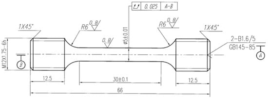
Figure 1.
Technical drawing of the tensile specimens (mm).
2.2. Slow Strain Rate Tensile Test
The susceptibility of T91 to LBE embrittlement was evaluated using the SSRT test. The equipment used to perform the SSRT test is a lead-bismuth liquid metal tensile fracture toughness testing system with a rated load of 50 kN. SSRT tests were performed in LBE and argon (Ar) environments with saturated oxygen concentrations at strain rates of 2 × 10⁻⁶/s and 1 × 10⁻⁵/s and test temperatures of 350 °C, 450 °C and 550 °C, respectively. The LME susceptibility of T91 in LBE was determined by comparing their tensile properties and fracture morphologies in both LBE and Ar at the same temperature. To evaluate the effect of the surface contact state between the specimen and the LBE on LME susceptibility, specimens were pre-exposed to low-oxygen LBE at 350 °C for 24 h and 48 h prior to the SSRT test to enhance surface wettability.
During the pre-exposure and SSRT tests, the dissolved oxygen concentration in the LBE was monitored by an electrochemical lead-bismuth alloy oxygen sensor. The reference electrode was Bi/Bi2O3, and the solid electrolyte was a YSZ ceramic tube (8 mol.% Y2O3 stabilized ZrO2), which had the characteristic of oxygen ion conduction at high temperatures. The lead wire of the reference electrode was Mo wire (diameter 0.5 mm). The dissolved oxygen content in LBE was calculated by measuring the oxygen concentration potential between the positive and negative electrodes of the electrochemical oxygen sensor using the following formula [20]:
where E is the electromotive force (V) measured by the oxygen sensor, T is the temperature in Kelvin (K), and CO is the oxygen concentration dissolved in LBE (wt.%).
E = −0.34756 + 2.5217 × 10⁻⁴T − 4.3086 × 10⁻⁵TlnCO
2.3. Microstructure Characterization
The initial microstructure of T91 was observed using metallographic microscopy. The phase compositions of T91 were analyzed by XRD (Bruker D8-Advance, BRUKER AXS GMBH, Karlsruhe, Germany). After the SSRT testing, LBE deposits on the fracture surface need to be cleaned. Cleaning with a chemical solution consisting of acetic acid (CH3COOH), ethanol (CH3CH2OH), and hydrogen peroxide (H2O2) with a volume ratio of 1:1:1. SEM (ZeissSupra55, Cael Zeiss AG, Jena, Germany) was used to observe the fracture morphology and surface cracks of the specimens; energy spectrometer (EDS, Bruker Quantax200, BRUKER AXS GMBH, Karlsruhe, Germany) was utilized to characterize the elemental composition of the specimens. The other parts of the specimens were not cleaned but embedded in conductive resin. The embedded specimens were polished along their longitudinal direction step by step using abrasive papers of 600, 1000, 1200, and 2000 grits, followed by fine polishing with 0.7 mm alumina and 0.05 mm silica suspension solutions.
3. Result
3.1. As-Received Microstructure
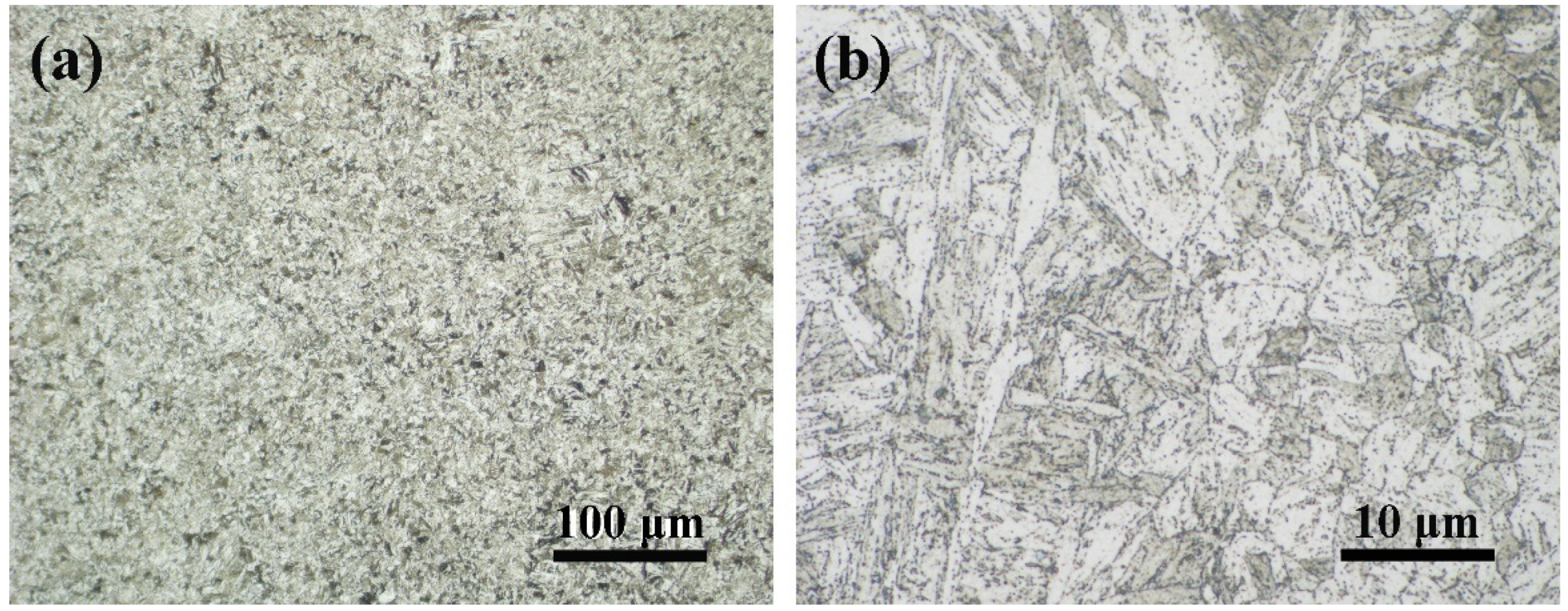
The initial structures of T91 can be seen from the optical microscope images shown in Figure 2. The specimens have a typical martensite lath structure, and the average size of the primary austenite grains is about 20 μm.
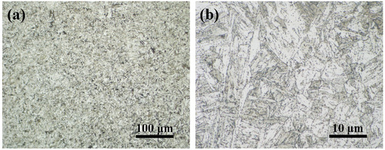
Figure 2.
Metallographic micrographs of T91, (a) 100 μm, (b) 10 μm.
3.2. Tensile Mechanical Behavior
3.2.1. Tested After Different Pre-Exposure
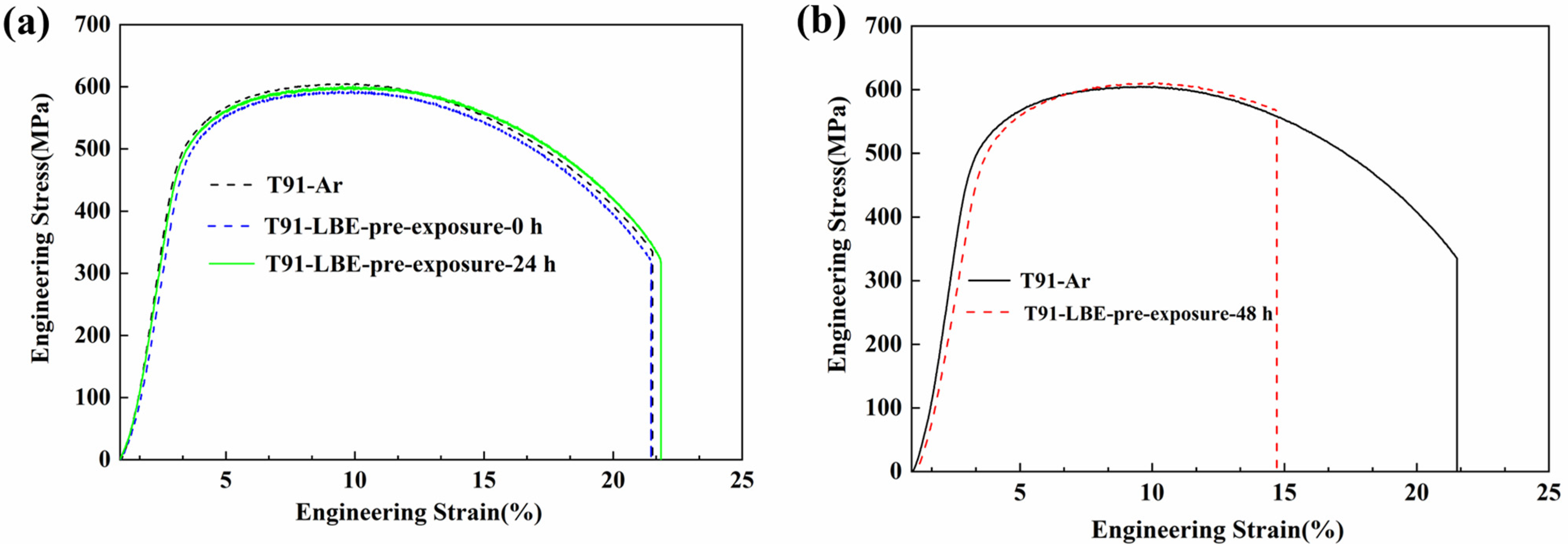
The engineering stress–strain tensile curves of T91 steel tested in Ar and oxygen-saturated LBE at 350 °C, both without pre-exposure and with pre-exposure in low-oxygen LBE (24 h, 48 h), are shown in Figure 3. The tests conducted in the LBE are nearly identical to those conducted in the Ar environment. The yield strength, tensile strength, and uniform elongation are essentially unaffected by the LBE environment. The only notable difference is a reduction in total elongation after 48 h of exposure to LBE compared to those of Ar environment, un-exposure (0 h), and short-term exposure (24 h) specimens.
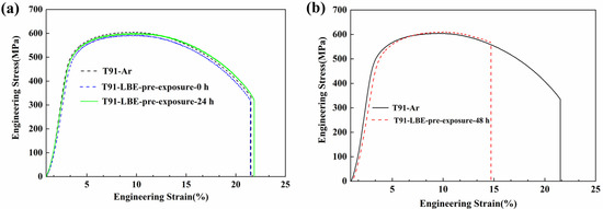
Figure 3.
Stress–strain curve of T91 steel in Ar and saturated oxygen LBE under different pre-exposure times, (a) 0 h and 24 h, (b) 48 h. The strain rate is 2 × 10⁻⁶/s.
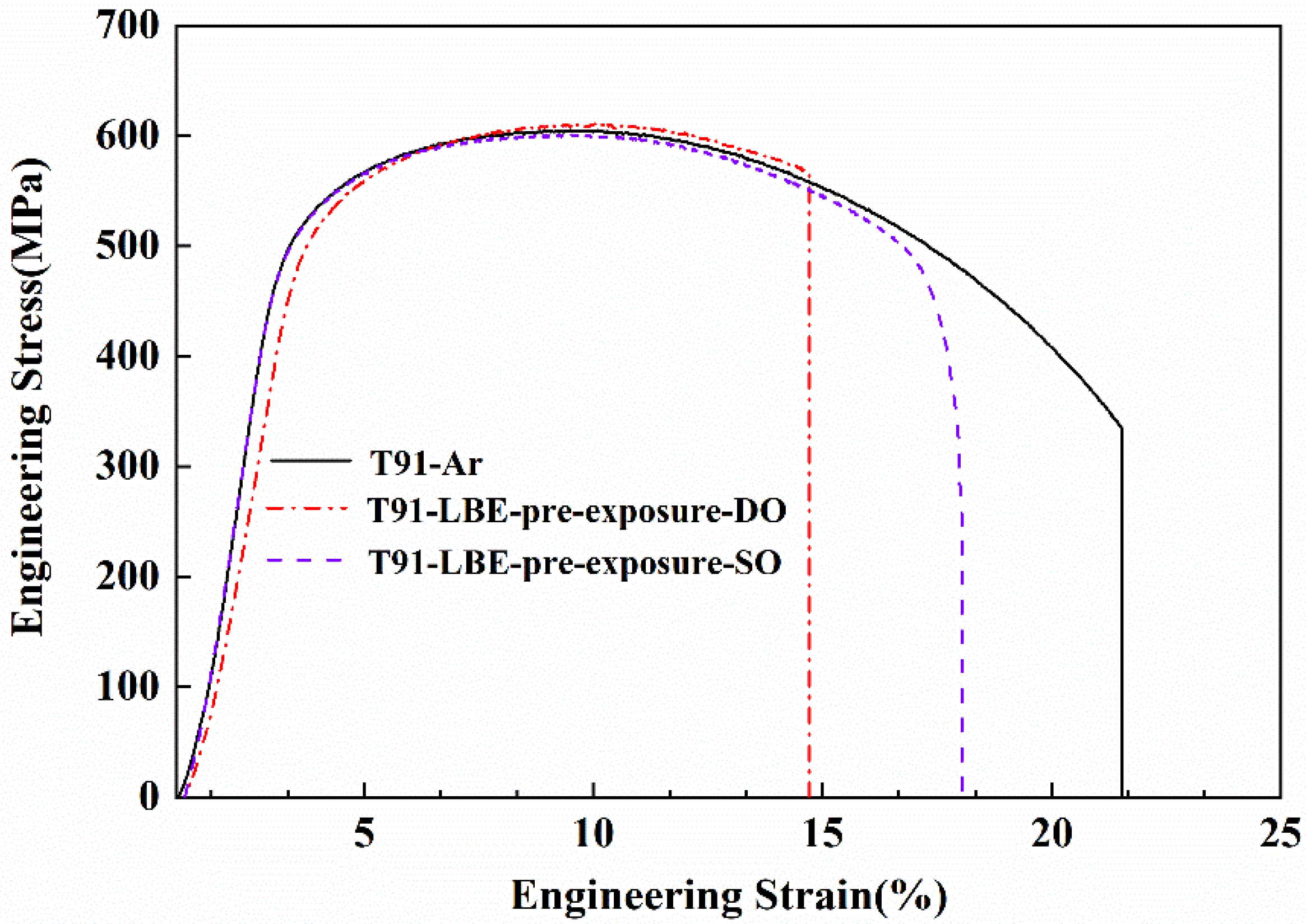
Figure 4 shows the effect of pre-exposure oxygen concentration on the tensile behavior of T91 steel tested in saturated oxygen LBE. When the pre-exposure oxygen concentration is depleted oxygen, the total elongation of the specimens in LBE is significantly lower than that in Ar, which is a typical LME phenomenon. However, when the pre-exposure oxygen concentration is saturated oxygen, the difference in total elongation between the specimens in Ar and LBE decreases, indicating that the LME phenomenon is weakened currently.
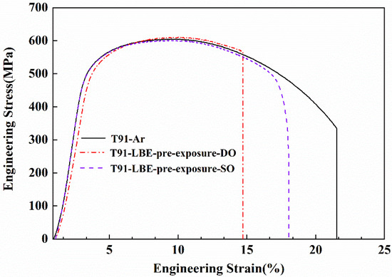
Figure 4.
Stress–strain curve of T91 steel in 350 °C Ar and saturated oxygen LBE under different pre-exposure oxygen concentrations. Saturated oxygen concentration (SO); depleted oxygen concentration (DO). The strain rate is 2 × 10⁻⁶/s.
3.2.2. Test at Different Temperature
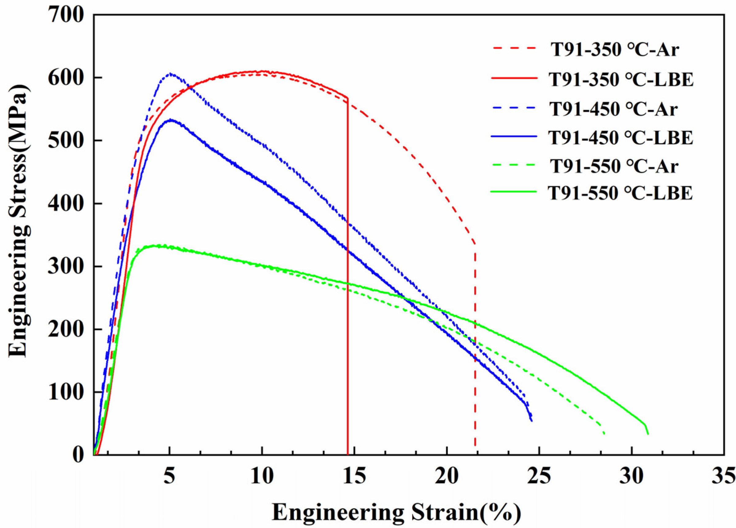
Figure 5 shows the engineering stress–strain curves of T91 steel tested in LBE at temperatures ranging from 350 °C to 550 °C. The total elongation of T91 shows a notable variation with temperature. At 350 °C, the total elongation in Ar is 21.2 %, whereas in LBE, it is 14.8%, suggesting premature fracture and a pronounced LME effect. As the temperature further increases to 450 °C and 550 °C, its elongation in Ar and LBE remains unchanged, and LME disappears. The above results indicate that the LME effect is most pronounced at 350 °C. When the temperature is further increased, the impact on total elongation diminishes, and the material’s plasticity is restored.

Figure 5.
Stress–strain curves (strain rate is 2 × 10⁻⁶/s) of T91 steel in Ar and saturated oxygen LBE at different temperatures (350 °C, 450 °C and 550 °C).
3.2.3. Test with Different Strain Rate
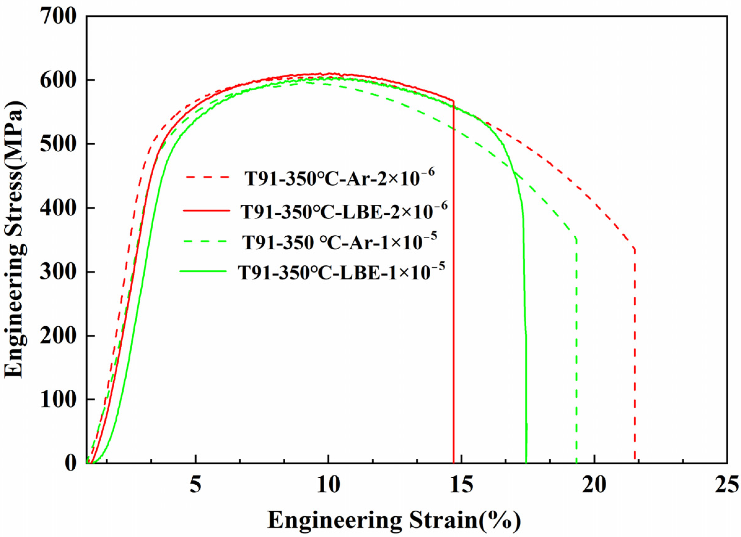
Figure 6 illustrates the impact of strain rate on the tensile behavior of T91 tested in saturated oxygen LBE. The figure demonstrates that the yield strength and ultimate tensile strength of T91 remain constant across different strain rates, indicating that these properties are not influenced by the strain rate.
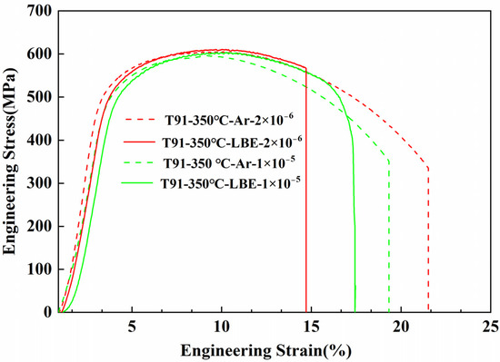
Figure 6.
Stress–strain curves of T91 steel at different strain rates (2 × 10⁻⁶/s and 1 × 10⁻⁵/s) in Ar and saturated oxygen LBE at 350 °C.
However, the total elongation of T91 steel is affected by the strain rate to some extent, especially in the liquid LBE environment, and the strain rate will significantly affect the LME sensitivity of the material. When the strain rate is low (2 × 10⁻⁶/s), the total elongation of the specimens in the Ar and LBE environment is significantly different (21.5% in Ar and 14.8% in LBE), indicating the existence of the LME effect. When the strain rate of the tensile test is increased (1 × 10⁻⁵/s), the difference between the total elongation of the specimens in Ar and LBE environments decreases significantly (19.1% in Ar and 17.4% in LBE). This indicates that the LME effect weakens or may disappear when the strain rate is larger. However, it needs to be further confirmed by SEM fracture analysis of the specimens.
3.3. SEM Fractography
Figure 7 shows the SEM fracture analysis results of T91 tested in Ar and LBE. In Ar, the specimens exhibit necking and numerous dimples, indicating ductile fracture (Figure 7a,b). In LBE, in LBE both with and without pre-exposure (24 h), the fracture characteristics of the specimens are like those in Ar (Figure 7c–f), also indicating ductile fracture.
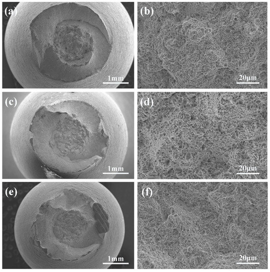
Figure 7.
SEM fractographic images of the specimens without pre-exposure tested in Ar (a,b) and LBE (c,d) and the specimens pre-exposure for 24 h tested in LBE (e,f).
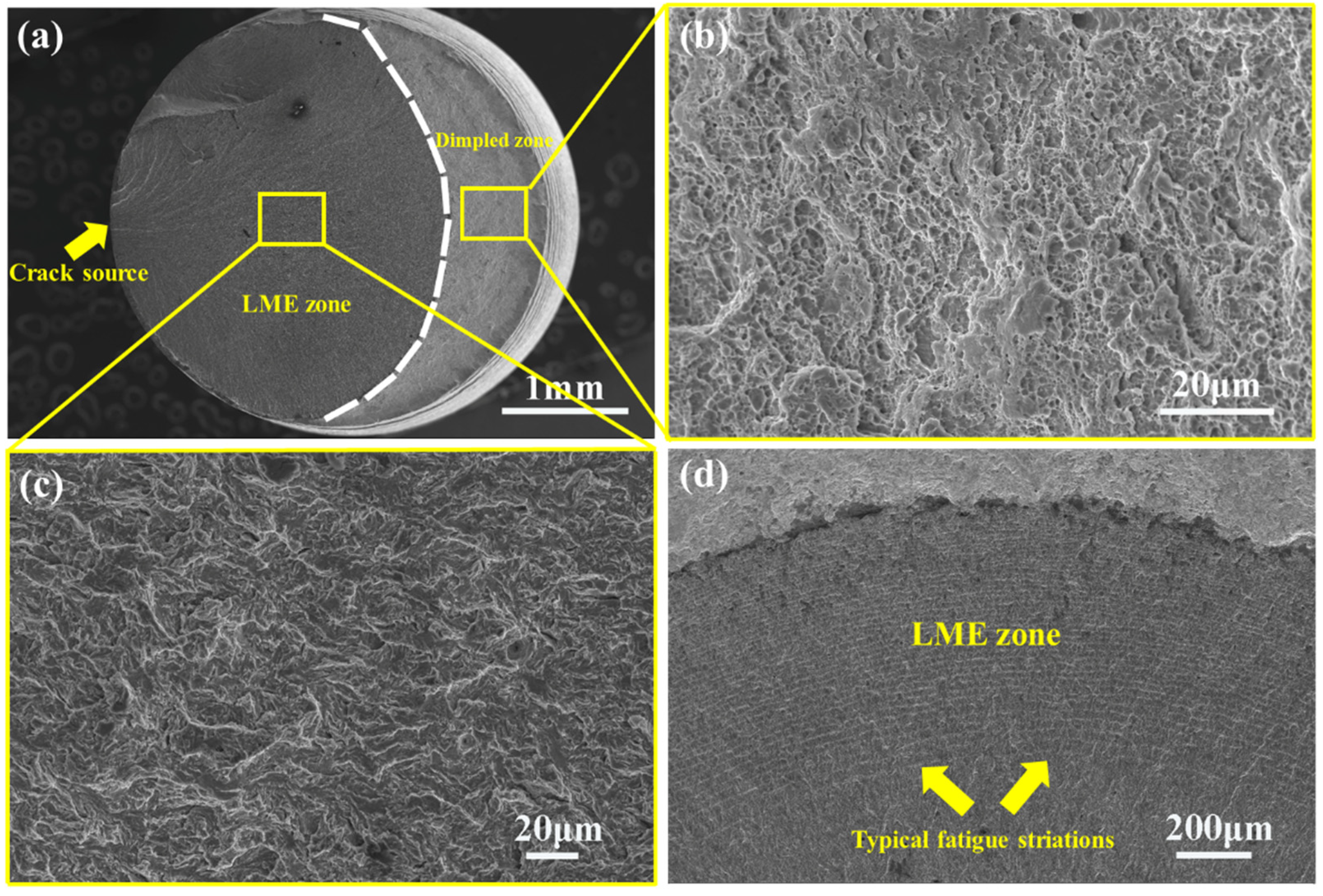
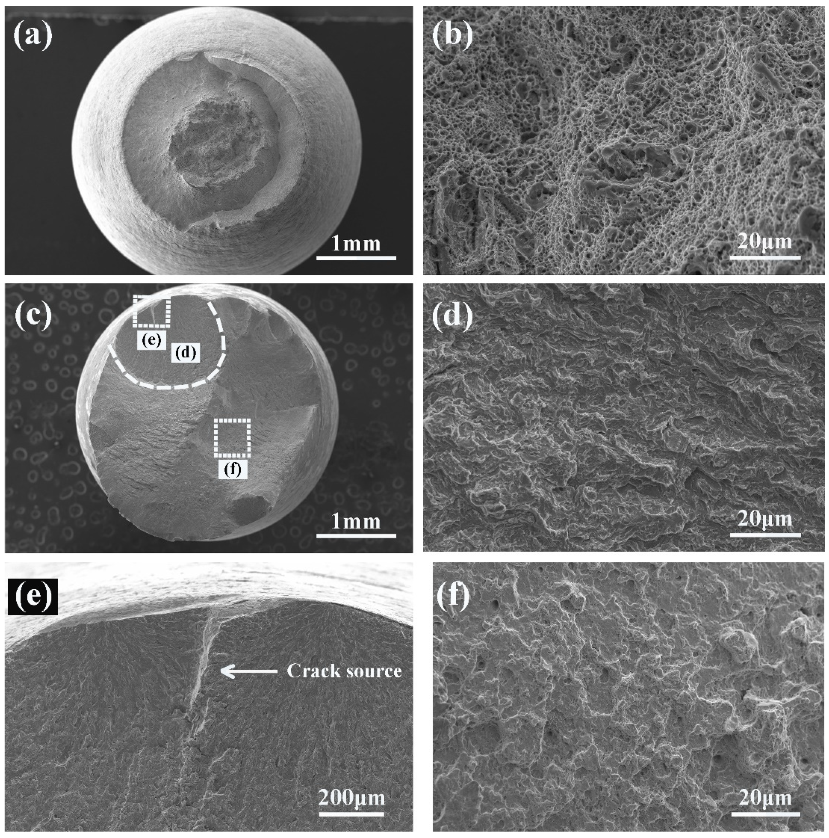
For specimens pre-exposed to LBE for 48 h, the fracture morphology changes significantly (see Figure 8). Figure 8a indicates that the specimen exhibits almost no necking prior to fracture, and a small part of the fracture surface shows dimples (Figure 8b), but the size and density of dimples are much smaller than those of the specimen tested in Ar and in LBE both with (24 h) and without pre-exposure. Most of the fracture surface was affected by LBE and showed river patterns (Figure 8c), which is a typical LME feature, indicating that the LME phenomenon occurred in the specimen. The crack source point of the specimen originates from the edge region (the direction indicated by the arrow in Figure 8a). The SEM images of the fracture surface suggest a pronounced LME effect that initiates at the surface and propagates inward, while competitive ductile fracture initiates internally and progresses through micropore coalescence, resulting in dimple formation.
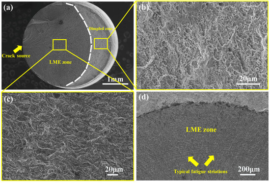
Figure 8.
Scanning electron microscope micrograph of the specimen pre-exposure to poor oxygen LBE for 48 h tested in LBE; (a) is a panoramic view, (b–d) are partial views.
Additionally, Figure 8d shows “striations” in the LME zone, resembling those found in fatigue fractures. These stripes may be due to the short pre-exposed time. At the beginning of tensile loading, the oxide film has not broken, and the crack initiation is delayed, while the ductile fracture mode of cavity agglomeration is taking place in the matrix [21]. Meanwhile, a large amount of elastic energy was gradually stored in the load line of the tensile machine, as the loading line was elastically deformed during the tensile loading process. At a certain moment of tensile loading, under the combined action of stress and LBE, the oxide film on the specimen surface is destroyed, and the close contact between the matrix and LBE results in the initiation of brittle cracks. The LME crack propagation was prompt and required little energy in the brittle fracture mode, leading to a sudden stress drop in the specimen. This drop in stress slows crack growth temporarily; as the stress increases again due to the resumed crack growth, the crack reinitiates, creating a “cyclic loading” effect like fatigue, thereby forming the striations observed on the fracture surface [22].
The fracture morphology results of T91 indicate that pre-exposure in the LBE environment significantly influences the LME effect. The LME effect on the material is most pronounced after 48 h of pre-exposure to the low-oxygen LBE.
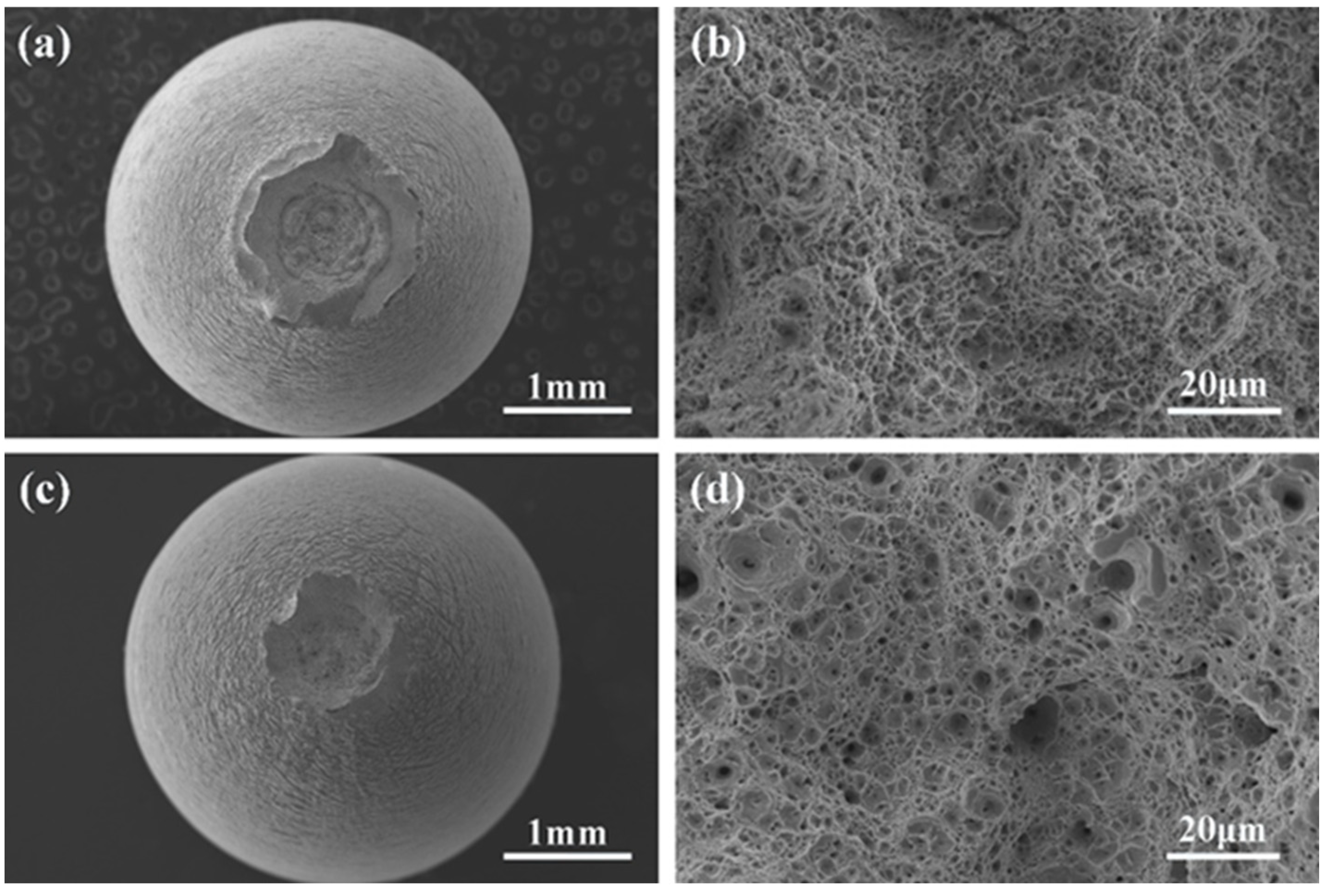
Figure 9 is the SEM image of the fracture specimens after LBE pre-exposure with saturated oxygen for 48 h. The crack source also started from the edge area, distributed like a river, and the fracture mode was a quasi-cleavage fracture. There are dimples in the central area of the specimens, but the number of dimples is greater than that of the specimen in poor oxygen LBE, as shown in Figure 9c. Unlike the pre-exposure specimen in low oxygen LBE, which did not undergo necking before fracture, the pre-exposure specimen in saturated oxygen LBE experienced slight necking before fracture. Most importantly, the brittle fracture area of the pre-exposure specimen in saturated oxygen LBE is significantly reduced. This result is consistent with the stress–strain curve, indicating that the LME phenomenon of T91 will be inhibited when the pre-exposure concentration is saturated oxygen.
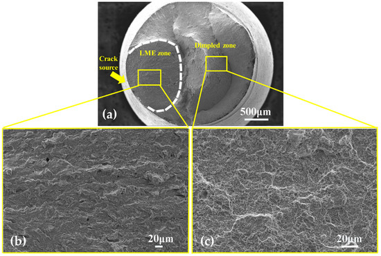
Figure 9.
Scanning electron microscope micrograph of the specimen pre-exposure to rich oxygen LBE for 48 h tested in LBE, (a) is a panoramic view, (b) is LME areas, (c) is dimple areas.
The fracture morphology of T91 changes significantly with increasing temperature, specifically at 450 °C and 550 °C. Figure 10 presents SEM images of the fracture surfaces of test specimens in LBE 48 h of pre-exposure at these elevated temperatures. Post-testing in LBE at 450 °C and 550 °C, the brittle fracture characteristics observed at lower temperatures are no longer present, and pronounced necking is evident. The higher the temperature, the more obvious necking, indicating a more ductile fracture behavior. The entire fracture surface is characterized by dimples, indicative of typical ductile fracture.

Figure 10.
Scanning electron microscope micrograph of the specimen after being tested in LBE at different temperatures shows that (a,b) is 450 °C and (c,d) is 550 °C.
This observation suggests that at a test temperature of 450 °C, ductile fracture predominates, and the LME phenomenon is not evident. LME effects in T91 occur primarily at the lower test temperature of 350 °C in LBE. This behavior aligns with the results observed in the stress–strain curves, confirming the temperature dependency of fracture mechanisms in T91 under LBE exposure.
Figure 8 and Figure 11 show the morphology of the tensile fracture at strain rates of 2 × 10⁻⁶/s and 1 × 10⁻⁵/s, respectively. In an Ar environment at 350 °C, when the strain rate is 1 × 10⁻⁵/s, the fracture surface of T91 shows obvious necking and dimples, which are typical ductile fracture characteristics. However, in an LBE environment at 350 °C, the fracture surface of T91 shows a central area with dimples and an edge region with a crack source, displaying a river-like fracture pattern. As shown in Figure 11c, when compared to the fracture morphology at the strain rate of 2 × 10⁻⁶/s, the brittle fracture area of T91 is noticeably smaller at the higher strain rate. This indicates that the lower strain rate promotes the LME phenomenon in T91.

Figure 11.
Scanning electron microscope micrograph of T91 steel after being tested in Ar and LBE at 350 °C when the strain rate is 1 × 10⁻⁵/s, (a,b) in Ar, (c–f) in LBE.
3.4. Surface Crack
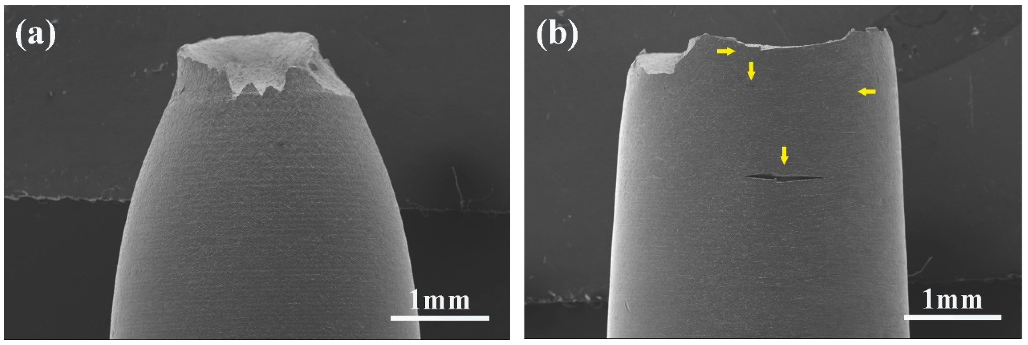
The surface cracking of T91 after testing in Ar and LBE environments is shown in Figure 12. The specimens tested in Ar do not exhibit significant surface cracks, as the ductile fracture mode involves void nucleation and coalescence in this environment. In contrast, T91 tested in LBE shows evident surface cracks (marked with yellow arrows in Figure 12b). This indicates that LBE contributes to the fracture of T91 [23].
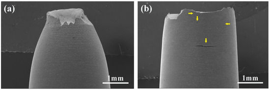
Figure 12.
SEM micrographs of the surface appearances of the T91 tested in Ar (a), LBE (b) (strain rate 2 × 10⁻⁶/s).
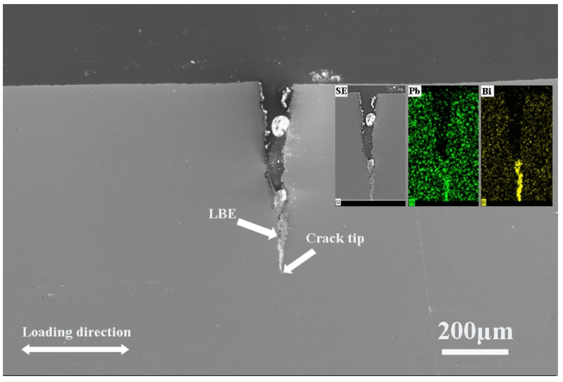
Figure 13 is a morphology diagram of the T91 after the tensile test in LBE, in which the specimens were longitudinally sectioned for SEM morphology observation and EDS surface scanning analysis. Obvious cracks were found near the fracture of the specimens and within the gauge length section. From the figure, Pb and Bi exist at the crack tip, indicating that during the tensile process, lead or bismuth fully contacts the specimen surface and expands along the crack in the direction of crack development, fully infiltrating the crack.

Figure 13.
Cracks near the fracture surface of T91 specimens in LBE at 350 °C (strain rate is 2 × 10⁻⁶/s).
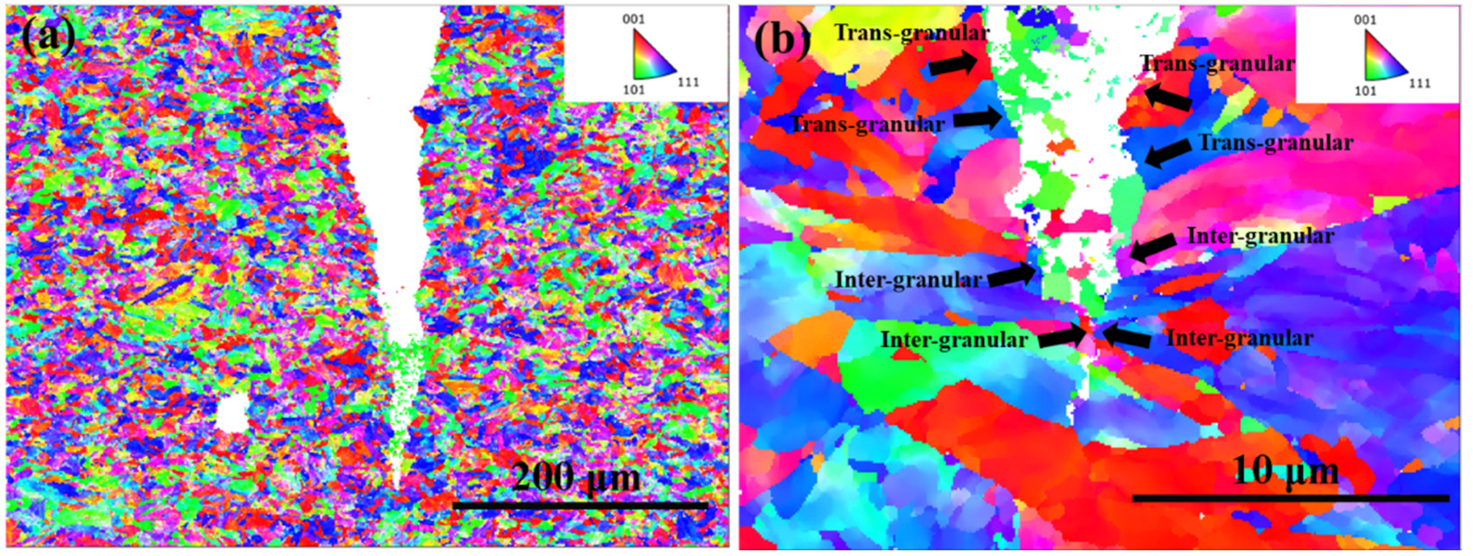
Figure 14 is the EBSD grain orientation map of T91 on both sides at 350 °C LBE. The crack tip of T91 specimens is smooth and has a wide crack width. It can be observed from Figure 14a,b that the crack propagation mode of T91 in LBE is a mixed propagation mode of intergranular and transgranular.

Figure 14.
EBSD grain orientation diagram of cracks in T91 specimens in LBE at 350 °C, (a) 200 μm, (b) 10 μm. (strain rate is 2 × 10⁻⁶/s).
4. Discussion
4.1. Effect of Pre-Exposure
The phenomenon of LME has garnered significant attention from researchers worldwide. Numerous studies have investigated various solid metal/liquid metal systems, proposing different mechanisms and models to explain the LME phenomenon [24,25,26,27]. However, no single model comprehensively covers all observed cases. Despite this, certain factors contributing to LME sensitivity are widely accepted. One such factor is the wettability between the material surface and the liquid metal, which is considered crucial for LME occurrence [18].
In this experiment, the total elongation of T91 in oxygen-saturated LBE was significantly lower than that in Ar after 48 h of pre-exposure in low oxygen LBE at 350 °C. The fracture surface analysis revealed a cleavage fracture, indicating a strong LME effect. Conversely, specimens without pre-exposure and those pre-exposed for 24 h showed no significant changes in total elongation, and their fracture surfaces indicated only ductile fracture, with no evidence of LME.
One of the necessary conditions for the LME of materials is the close contact between the metal matrix and LBE. T91, containing 9% chromium, easily forms an oxide layer on the surface, which will prevent close contact between matrix steel and liquid LBE. If the oxide layer can remain intact during the mechanical loading of steel, the LME phenomenon will not occur.
The absence of LME in the non-pre-exposed specimens and the specimens pre-exposed to low-oxygen LBE for 24 h suggests that the steel substrate was not wetted by LBE. However, specimens pre-exposed for 48 h exhibited a clear LME effect after SSRT, indicating that the steel matrix was in direct contact with LBE. Figure 13 shows that Pb and Bi exist at the crack tip, indicating that during the tensile process, lead or bismuth fully contacts the specimen surface and expands along the crack in the direction of crack development, fully infiltrating the crack.
Figure 12 shows that T91 pre-exposed for 48 h has more surface cracks and longer lengths after the SSRT test. The fracture SEM image shows that the crack source is located at the edge of the fracture. This is because under the tensile stress, the weak points in the oxide layer are easily broken and no longer play a protective role. Hence, the fresh matrix is directly exposed to LBE, which promotes the initiation of surface cracks. Therefore, T91 has an obvious LME effect after being pre-exposed to low-oxygen LBE for 48 h.
In addition, the cleavage fracture area of the specimens tested in saturated oxygen LBE was significantly smaller than that of the specimens pre-exposure to low oxygen LBE, indicating that the specimens pre-exposure in saturated oxygen LBE also had an LME effect, but its LME sensitivity was lower than that of the specimens pre-exposure in low oxygen LBE. This shows that pre-exposure under saturated oxygen conditions can only delay or inhibit the occurrence of LME but cannot completely avoid the LME phenomenon.
4.2. Effect of Temperature and Strain Rate
Despite extensive research over the past few decades, the potential mechanism of the LME remains not fully elucidated due to its complexity. One important reason for this is that LME sensitivity is influenced by numerous parameters, including temperature, strain rate, oxygen concentration, and material composition. Among these, temperature and strain rate are the key factors affecting LME sensitivity, and their specific impacts have yet to be fully resolved.
In oxygen-saturated LBE at 350 °C, the total elongation of T91 significantly decreases when the strain rate of T91 is 2 × 10⁻⁶/s. However, increasing the temperature to 450 °C and 550 °C results in a clear increase in total elongation. SEM images of the fracture surfaces show typical quasi-cleavage characteristics after testing in LBE at 350 °C, indicating the occurrence of the LME effect at this temperature. At 450 °C and 550 °C, the fracture mode shifts to ductile fracture, suggesting that the LME phenomenon disappears at these higher temperatures. This indicates that the LME effect occurs only within a specific temperature range. Previous literature also demonstrates that LME sensitivity is highly temperature-dependent. For total strain, there is a “ductility trough” where LME sensitivity is highest; beyond this range, LME becomes weak or absent [16,28,29,30]. Our experimental results support this conclusion.
There are two primary reasons for the disappearance of the LME phenomenon at high temperatures. First, dislocation mobility increases with temperature, which blunts the crack tip and restores ductility [31]. This is evident in Figure 10, where T91 shows more pronounced necking at 550 °C. Second, the adsorption kinetics of LBE atoms at the crack tip are temperature-dependent. At high temperatures, desorption and adsorption compete, with desorption processes inhibiting the close contact between LBE and the crack tip [32], potentially leading to restored material ductility [30].
The effect of strain rate on LME is influenced by three competing factors. Firstly, the wetting of the steel surface or crack tip by LBE is time-dependent, with lower strain rates facilitating more extensive interaction between LBE and the crack tip, thereby promoting LME [17]. Secondly, low strain rates allow more time for oxygen to diffuse into the damaged area, healing the oxide layer and making it more stable, which can limit LME occurrence [33]. Lastly, stress relaxation at the crack tip can occur at a lower strain rate, making it difficult to reach the threshold stress required for crack initiation, thus preventing LME [34].
From the stress–strain curve and fracture morphology, it is evident that at a low strain rate, the total elongation of T91 in LBE significantly decreases compared to that in Ar, while the cleavage fracture area increases, indicating a predominance of brittle fracture. This suggests that the degree of brittle fracture in T91 decreases with increasing strain rates. These findings align with the first case, where a low strain rate allows for full wetting of the LBE and crack tip, effectively promoting the LME effect.
5. Conclusions
LME sensitivity studies were carried out on T91 in oxygen-saturated LBE under various temperatures, pre-exposure conditions, and strain rates. The following conclusions can be drawn:
- (1)
- Effect of pre-exposure on LME
- T91 steel pre-exposure in low oxygen LBE for 48 h showed a significant LME effect in the LBE environment at 350 °C, which was characterized by a sharp decrease in elongation and brittle fracture.
- There were many long cracks on the surface of the specimens, and the SEM images of the fracture surface showed that the crack source was located at the edge of the fracture surface. This was because the pre-exposure caused the T91 steel matrix to be in close contact with LBE, which promoted the initiation of surface cracks, resulting in the LME phenomenon.
- (2)
- Effect of temperature on LME
- T91 exhibits LME sensitivity at 350 °C. When the temperature is increased to 450 °C and 550 °C, the LME phenomenon disappears.
- This is attributed to increased dislocation mobility at higher temperatures, which blunts the crack tip and restores material ductility. Additionally, the adsorption kinetics of LBE atoms at the crack tip and desorption at high temperatures contribute to this effect.
- (3)
- Effect of strain rate on LME
- LME sensitivity in T91 increases at lower strain rates. Low strain rates allow for thorough wetting of the LBE and crack tip, thus promoting LME phenomena.
The present study highlights the critical role of pre-exposure, temperature, and strain rate in influencing the LME behavior of T91 in an LBE environment, which provides an important basis for optimizing the selection of structural materials and operating parameters in lead-bismuth cooling system.
Author Contributions
Conceptualization, J.Z.; methodology, J.Z. and B.Q.; validation, J.Z.; formal analysis, J.Z. and B.Q.; investigation, J.Z.; resources, J.Z. and B.Q.; data curation, J.Z.; writing—original draft preparation, J.Z.; writing—review and editing, B.L.; visualization, J.Z.; supervision, B.L. All authors have read and agreed to the published version of the manuscript.
Funding
This work was supported by China National Nuclear Corporation’s Pioneer Research Project (Project Name: Study on Micro-interface and Mass Exchange Characteristics of PbO Based on Solid-state Oxygen Control of Pb-Bi Alloy, No. FJ222508000702).
Data Availability Statement
The data presented in this study are openly available in [Effect of contact conditions on embrittlement of T91 steel by lead–bismuth] at [https://doi.org/10.1016/j.jnucmat.2004.07.025], reference number [18].
Conflicts of Interest
The authors declare no conflicts of interest.
References
- Khan, M.S.; Bai, Y.; Chen, Z.; Huang, Q.; Zou, X. Conceptual design and numerical assessment of compact heat exchanger for lead-based reactor. Prog. Nucl. Energy 2020, 124, 103348. [Google Scholar] [CrossRef]
- Zrodnikov, A.V.; Toshinsky, G.I.; Komlev, O.G.; Stepanov, V.S.; Klimov, N.N. SVBR-100 module-type fast reactor of the IV generation for regional power industry. J. Nucl. Mater. 2011, 415, 237–244. [Google Scholar] [CrossRef]
- Lorusso, P.; Bassini, S.; Del Nevo, A.; Di Piazza, I.; Giannetti, F.; Tarantino, M.; Utili, M. GEN-IV LFR development: Status & perspectives. Prog. Nucl. Energy 2018, 105, 318–331. [Google Scholar]
- Gong, X.; Li, R.; Sun, M.; Ren, Q.; Liu, T.; Short, M.P. Opportunities for the LWR ATF materials development program to contribute to the LBE-cooled ADS materials qualification program. J. Nucl. Mater. 2016, 482, 218–228. [Google Scholar] [CrossRef]
- Lu, Y.; Zhu, R.; Fu, Q.; Wang, X.; An, C.; Chen, J. Research on the structure design of the LBE reactor coolant pump in the lead base heap. Nucl. Eng. Technol. 2019, 51, 546–555. [Google Scholar] [CrossRef]
- Van den Bosch, J.; Bosch, R.W.; Sapundjiev, D.; Almazouzi, A. Liquid metal embrittlement susceptibility of ferritic–martensitic steel in liquid lead alloys. J. Nucl. Mater. 2008, 376, 322–329. [Google Scholar] [CrossRef]
- Zhang, J.; Li, N. Review of the studies on fundamental issues in LBE corrosion. J. Nucl. Mater. 2008, 373, 351–377. [Google Scholar] [CrossRef]
- Schroer, C.; Wedemeyer, O.; Skrypnik, A.; Novotny, J.; Konys, J. Corrosion kinetics of Steel T91 in flowing oxygen-containing lead–bismuth eutectic at 450 °C. J. Nucl. Mater. 2012, 431, 105–112. [Google Scholar] [CrossRef]
- Martinelli; Jean-Louis; Fanny, B.C. Oxidation of steels in liquid lead bismuth: Oxygen control to achieve efficient corrosion protection. Nucl. Eng. Des. 2011, 241, 1288–1294. [Google Scholar] [CrossRef]
- Beal, C.; Kleber, X.; Fabregue, D.; Bouzekri, M. Liquid zinc embrittlement of twinning-induced plasticity steel. Scr. Mater. 2012, 66, 1030–1033. [Google Scholar] [CrossRef]
- Nicaise, G.; Legris, A.; Vogt, J.B.; Foct, J. Embrittlement of the martensitic steel 91 tested in liquid lead. J. Nucl. Mater. 2001, 296, 256–264. [Google Scholar] [CrossRef]
- Hojna, A.; Di Gabriele, F.; Chocholousek, M.; Spirit, Z.; Halodova, P.; Lorincik, J. Initiation of LME crack in ferritic martensitic steel in liquid lead-bismuth. J. Nucl. Mater. 2018, 511, 459–472. [Google Scholar] [CrossRef]
- Dai, Y.; Long, B.; Groeschel, F. Slow strain rate tensile tests on T91 in static lead–bismuth eutectic. J. Nucl. Mater. 2006, 356, 222–228. [Google Scholar] [CrossRef]
- Hojna, A.; Di Gabriele, F. On the kinetics of LME for the ferritic–martensitic steel T91 immersed in liquid PbBi eutectic. J. Nucl. Mater. 2011, 413, 21–29. [Google Scholar] [CrossRef]
- Gong, X.; Chen, J.; Xiang, C.; Yu, Z.; Gong, H.; Yin, Y. A comparative study on liquid metal embrittlement susceptibility of three FeCrAl ferritic alloys in contact with liquid lead-bismuth eutectic at 350 °C. Corros. Sci. 2021, 183, 109346. [Google Scholar] [CrossRef]
- Liu, J.; Yan, W.; Sha, W.; Wang, W.; Shan, Y.; Yang, K. Effects of temperature and strain rate on the tensile behaviors of SIMP steel in static lead bismuth eutectic. J. Nucl. Mater. 2016, 473, 189–196. [Google Scholar] [CrossRef]
- Ye, C.; Vogt, J.B.; Serre, I.P. Liquid metal embrittlement of the T91 steel in lead bismuth eutectic: The role of loading rate and of the oxygen content in the liquid metal. Mater. Sci. Eng. A 2014, 608, 242–248. [Google Scholar] [CrossRef]
- Auger, T.; Lorang, G.; Guérin, S.; Pastol, J.L.; Gorse, D. Effect of contact conditions on embrittlement of T91 steel by lead–bismuth. J. Nucl. Mater. 2004, 335, 227–231. [Google Scholar] [CrossRef]
- Vogt, J.B.; Proriol-Serre, I. Fatigue behaviour of a martensitic and an austenitic steel in heavy liquid metals. Procedia Eng. 2013, 55, 812–818. [Google Scholar] [CrossRef]
- Chen, G.; Zhang, Z.; Feng, S.; Jiang, K.; Yu, J.; Wu, H.; Shi, S.; Lin, Q. Improvement of low-cycle fatigue behavior of modified 9Cr-1Mo steels at 450 °C in liquid LBE environment by the addition of Si element. Nucl. Eng. Design 2023, 413, 112570. [Google Scholar] [CrossRef]
- Liu, J.; Xiao, Z.; Jiang, Z.; Luo, L. Liquid lead–bismuth eutectic embrittlement effect on the tensile properties of T91 steel at 350 °C. Mater. Corros. 2022, 73, 207–216. [Google Scholar] [CrossRef]
- Gong, X.; Stergar, E.; Marmy, P.; Gavrilov, S. Tensile fracture behavior of notched 9cr-lmo ferritic-martensitic steel specimens in contact with liquid lead-bismuth eutectic at 350 °C. Mater. Sci. Eng. A 2017, 692, 139–145. [Google Scholar] [CrossRef]
- Van den Bosch, J.; Coen, G.; Hosemann, P.; Maloy, S.A. On the LME susceptibility of Si enriched steels. J. Nucl. Mater. 2012, 429, 105–112. [Google Scholar] [CrossRef]
- Stoloff, N.S.; Johnston, T.L. Crack propagation in a liquid metal environment. Acta Metall. 1963, 11, 251–256. [Google Scholar] [CrossRef]
- Westwood, A.R.; Kamdar, M.H. Concerning liquid metal embrittlement, particularly of zinc monocrystals by mercury. Philos. Mag. 1963, 8, 787–804. [Google Scholar] [CrossRef]
- Fernandes, P.J.; Jones, D.R. Mechanisms of liquid metal induced embrittlement. Int. Mater. Rev. 1997, 42, 251–261. [Google Scholar] [CrossRef]
- Kolman, D.G. A review of recent advances in the understanding of liquid metal embrittlement. Mater. Corros. 2019, 75, 42–57. [Google Scholar] [CrossRef]
- Long, B.; Tong, Z.; Gröschel, F.; Dai, Y. Liquid Pb–Bi embrittlement effects on the T91 steel after different heat treatments. J. Nucl. Mater. 2008, 377, 219–224. [Google Scholar] [CrossRef]
- Long, B.; Dai, Y. Investigation of LBE embrittlement effects on the fracture properties of T91. J. Nucl. Mater. 2008, 376, 341–345. [Google Scholar] [CrossRef]
- Hadjem-Hamouche, Z.; Auger, T.; Guillot, I. Temperature effect in the maximum propagation rate of a liquid metal filled crack: The T91 martensitic steel/Lead–Bismuth Eutectic system. Corros. Sci. 2009, 51, 2580–2587. [Google Scholar] [CrossRef]
- Gong, X.; Hu, F.; Chen, J.; Wang, H.; Gong, H.; Xiao, J.; Wang, H.; Deng, Y.; Pang, B.; Huang, X.; et al. Effect of temperature on liquid metal embrittlement susceptibility of an Fe10Cr4Al ferritic alloy in contact with stagnant lead-bismuth eutectic. J. Nucl. Mater. 2020, 537, 152196. [Google Scholar] [CrossRef]
- Gong, X.; Marmy, P.; Qin, L.; Verlinden, B.; Wevers, M.; Seefeldt, M. Temperature dependence of liquid metal embrittlement susceptibility of a modified 9Cr–1Mo steel under low cycle fatigue in lead–bismuth eutectic at 160–450 °C. J. Nucl. Mater. 2016, 468, 289–298. [Google Scholar] [CrossRef]
- Gong, X.; Marmy, P.; Yin, Y. The role of oxide films in preventing liquid metal embrittlement of T91 steel exposed to liquid lead-bismuth eutectic. J. Nucl. Mater. 2018, 509, 401–407. [Google Scholar] [CrossRef]
- Gorse, D.; Auger, T.; Vogt, J.B.; Serre, I.; Weisenburger, A.; Gessi, A.; Agostini, P.; Fazio, C.; Hojna, A.; Di Gabriele, F.; et al. Influence of liquid lead and lead–bismuth eutectic on tensile, fatigue and creep properties of ferritic/martensitic and austenitic steels for transmutation systems. J. Nucl. Mater. 2011, 415, 284–292. [Google Scholar] [CrossRef]


Disclaimer/Publisher’s Note: The statements, opinions and data contained in all publications are solely those of the individual author(s) and contributor(s) and not of MDPI and/or the editor(s). MDPI and/or the editor(s) disclaim responsibility for any injury to people or property resulting from any ideas, methods, instructions or products referred to in the content. |
© 2025 by the authors. Licensee MDPI, Basel, Switzerland. This article is an open access article distributed under the terms and conditions of the Creative Commons Attribution (CC BY) license (https://creativecommons.org/licenses/by/4.0/).