Abstract
This study proposed a new method for homogenizing continuous casting blooms based on solidification simulation calculations and industrial tests. The text describes a theoretical analysis of the solidification route of a cast billet of high-carbon alloy steel (B300A) under different process conditions. It summarizes the changing law of different under-pressure process parameters and under-pressure efficiency. The text also presents a solution to the seriousness of center shrinkage defects in the continuous casting of a large square billet of high-carbon alloy steel with the synergistic control technology of mixed light and heavy mixing under pressure. The study indicates that the center carbon segregation index of a high carbon steel continuous casting billet is 1.05, with a carbon extreme difference of not more than 0.08% and a proportion of 98.4%. Additionally, the center shrinkage is not more than a 0.5 level with a proportion of 99.5%. Meanwhile, the internal quality of cast billets has been improved, allowing for the rolling of large-size bars with a low consolidation ratio. The pass rate for internal ultrasonic flaw detection using the GB/T4162A grade is now higher than 99.95%, significantly reducing process costs and improving production efficiency for continuous casting and rolling.
1. Introduction
High-carbon alloy steel usually contains 0.6–1.3% carbon, which refines the domains of martensite (packet) and bar bundles (block), resulting in improved strength and excellent mechanical properties. This has attracted the attention of scholars worldwide and has been widely applied [1]. However, steel with a high carbon content can lead to a wider solidification range, resulting in a larger paste zone. These large billet sections are more prone to macro segregation, which can cause center segregation, sparsity, and shrinkage during the continuous casting process. Billets with a side length greater than 220 mm are commonly referred to as ‘big billets’. This results in an uneven chemical composition, which is difficult to eliminate or improve to a greater extent in subsequent rolling and heat treatments. As a result, this is the main problem affecting the internal quality of the billet [2,3].
Macro segregation is the phenomenon in which the concentration of solute elements in the solid-liquid two-phase solubility differs, leading to a redistribution of elements during the solidification process and resulting in a concentration difference between the solid-liquid two phases [4,5,6]. The formation of billet segregation is typically attributed to the solidification process. If the columnar crystal growth rate of the billet is too fast, it can result in the formation of a lap bridge at the center of the billet during solidification due to non-uniform heat transfer during the casting process of high carbon steel. This can prevent the upper part of the steel from replenishing the lower part of the steel in a timely manner, leading to segregation at the center of the lower part of the steel [7,8].
The term ‘soft reduction’ refers to the reduction that occurs at the end of solidification. This technique can improve the effect of central segregation by compensating for solidification shrinkage and preventing solute enrichment [9,10,11]. The process of implementing soft reduction involves applying pressure through the pinch roller and straightening roller at the solidification end of continuous casting billet. The residual liquid phase between dendrites is caused by pressure, which gathers and moves upstream. This process compensates for solidification shrinkage and alters the solidification process in the central region, inhibiting segregation and internal defects such as looseness. As a result, the billet casting’s internal quality improves [12]. The effect of soft reduction technology is impacted by various process parameters. The reduction interval, generally between 0.2 and 0.8, is related to the solid phase rate of the cast billet [13,14,15,16]. Researchers have identified two intervals in the solidification front of the cast billet: the liquid-phase complementary shrinkage zone and the crack-generating zone. When the solid phase rate in the center of the billet is between 0.4 and 0.8, it is the liquid-phase complementary shrinkage zone. In this zone, the solute can more effectively fill the cracks, preventing their formation. Zones with solid phase ratios ranging from 0.8 to 0.99 are known to generate cracks due to dendritic arms impeding the filling of the steel, which can result in reduction cracks.
When selecting the reduction interval, it is important to avoid the crack-sensitive zone. The study has shown that to achieve better results with the light compression technique, it is necessary to consider the amount of compression.
Reasonable undercutting of the big billet at the end of the solidification can compensate for the solidification shrinkage in the paste zone, effectively reducing center loosening and center segregation within the cast billet. It should be noted that the two-phase region of medium and high carbon steel is wider, making it more susceptible to defects such as center segregation, shrinkage, and porosity [17,18]. However, when dealing with large cross-section blooms, center mass defects are more likely to occur, requiring a larger reduction to compensate for solidification shrinkage. To address this issue, researchers have proposed a continuous forging technique for the continuous casting of blooms [19,20]. This technique involves squeezing the solute-rich steel upstream through continuous forging at the solidification end. For light pressing, the reduction volume includes solidification shrinkage and the plastic deformation of the billet shell in the thickness direction during pressing. In contrast, continuous forging requires squeezing out the high concentration of liquid phase by crushing the solid phase in the two-phase region. The reduction volume of this process is much larger than that of light pressing. Therefore, heavy pressing technology, which applies greater pressure, is gradually being implemented to enhance the quality of the billet’s center [21,22,23].
This paper proposes the end light and heavy mixed reduction technology for the production of a 250 mm × 280 mm rectangular bloom continuous casting machine based on the production line of short-flow high-carbon alloy steel. The study shows that industrial test verification has effectively solved the problem of segregation and center quality of continuous casting bloom. This text describes a new homogenization path or reference for continuous casting lines of various steel grades and sizes.
2. Background
2.1. Continuous Casting Equipment
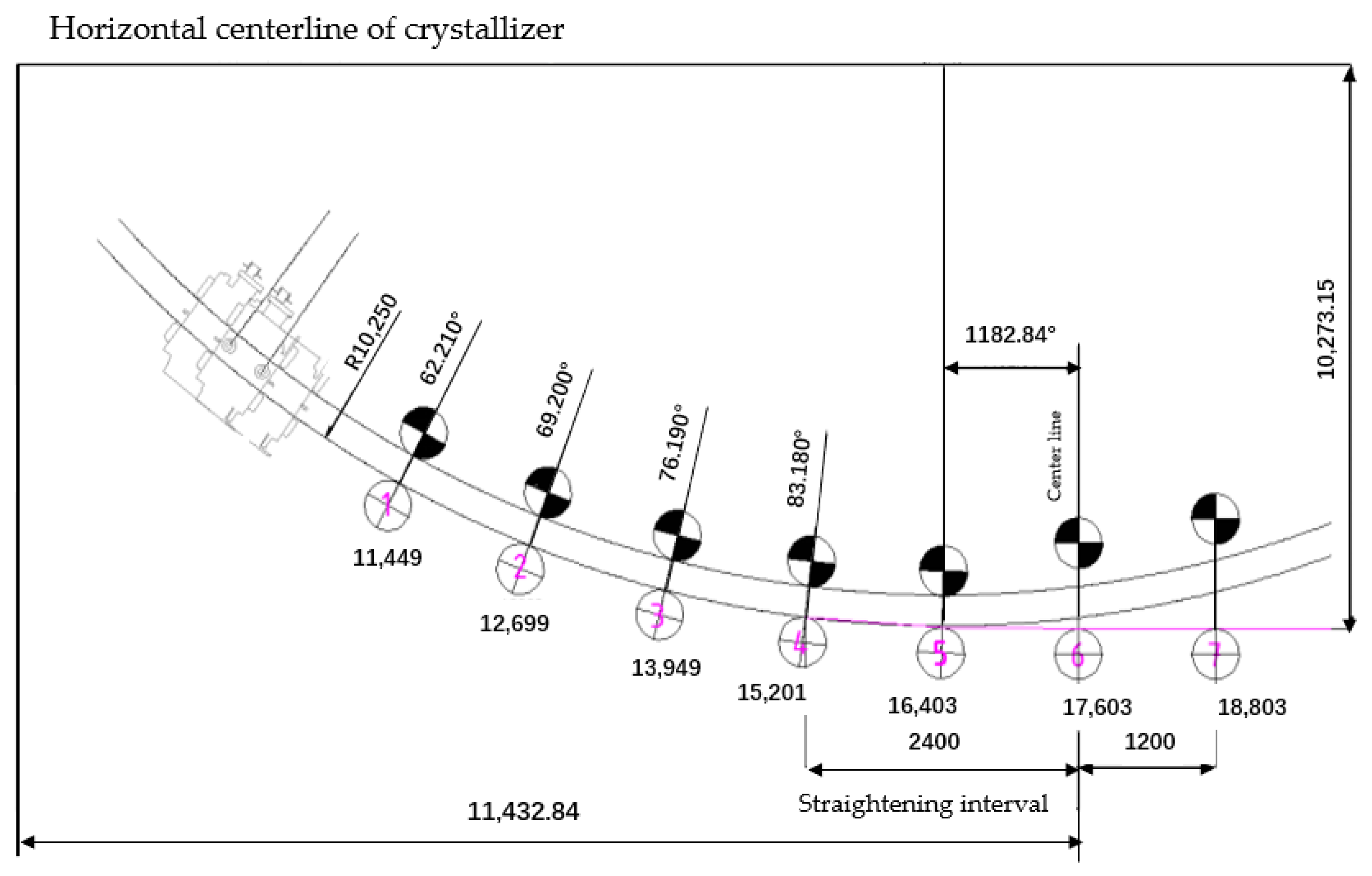
Figure 1 illustrates the arrangement of straightening machines with dense rows of racks spaced at 1250 mm, enabling precise alignment with the liquid core. Each stream is equipped with seven straightening machines. The cylinder diameter must be greater than or equal to 250 mm, and the roll diameter must be greater than or equal to 420 mm. The maximum output power should be 5.5 kW, with a maximum output pressure of 15 MPa and a maximum reduction of 5.0 mm. The theoretical total reduction should be between 20–35 mm, meeting the technical requirements for light and heavy mixed reduction. The seven drawing and straightening machines used in light pressing are controlled by a proportional servo system. This system forms a closed-loop control with the position sensor on the hydraulic cylinder when a light pressing position control is required, and with the pressure sensor when pressure control is necessary. The first to fourth drawing machines are also used for clamping ingot rods, and their motors are equipped with brakes. The remaining three frames are also equipped with brakes to facilitate the interchangeability of spare parts and to increase the clamping force when the middle pack is changed quickly.

Figure 1.
The layout of the straightening machine.
2.2. Solidification Characteristics of High-Carbon Alloy Steel for Continuous Casting
High carbon alloy steel is a type of steel with a carbon content ranging from 0.6% to 1.0%, manganese content ranging from 0.7% to 1.0%, and chromium content ranging from 0.5% to 1.5%. Some types may also contain varying amounts of silicon and molybdenum. The composition of the steel directly affects the characteristics of continuous casting solidification. This paper presents an example of a high-carbon alloy steel, B300A, and its main components are listed in Table 1. This paper focuses on B300A, whose physical parameters vary depending on the physical phase during solidification. Table 2 displays the thermal conductivity, specific heat capacity, and density values of B300A in the solid phase region, liquid phase region, and solid-liquid two-phase region at different temperatures.

Table 1.
Chemical composition of steel grade studied in weight%.
Table 2.
Physical parameters of B300A steel.
The thermal conductivity of the liquid-phase zone is m times that of the liquid steel at rest, λl = mλ, taking into account the effect of liquid steel flow. Table 3 shows the values of m in different cooling zones and the thermal conductivity of each zone.
Table 3.
Values of m taken in each cooling zone and liquid phase thermal conductivity, W/(m·K).
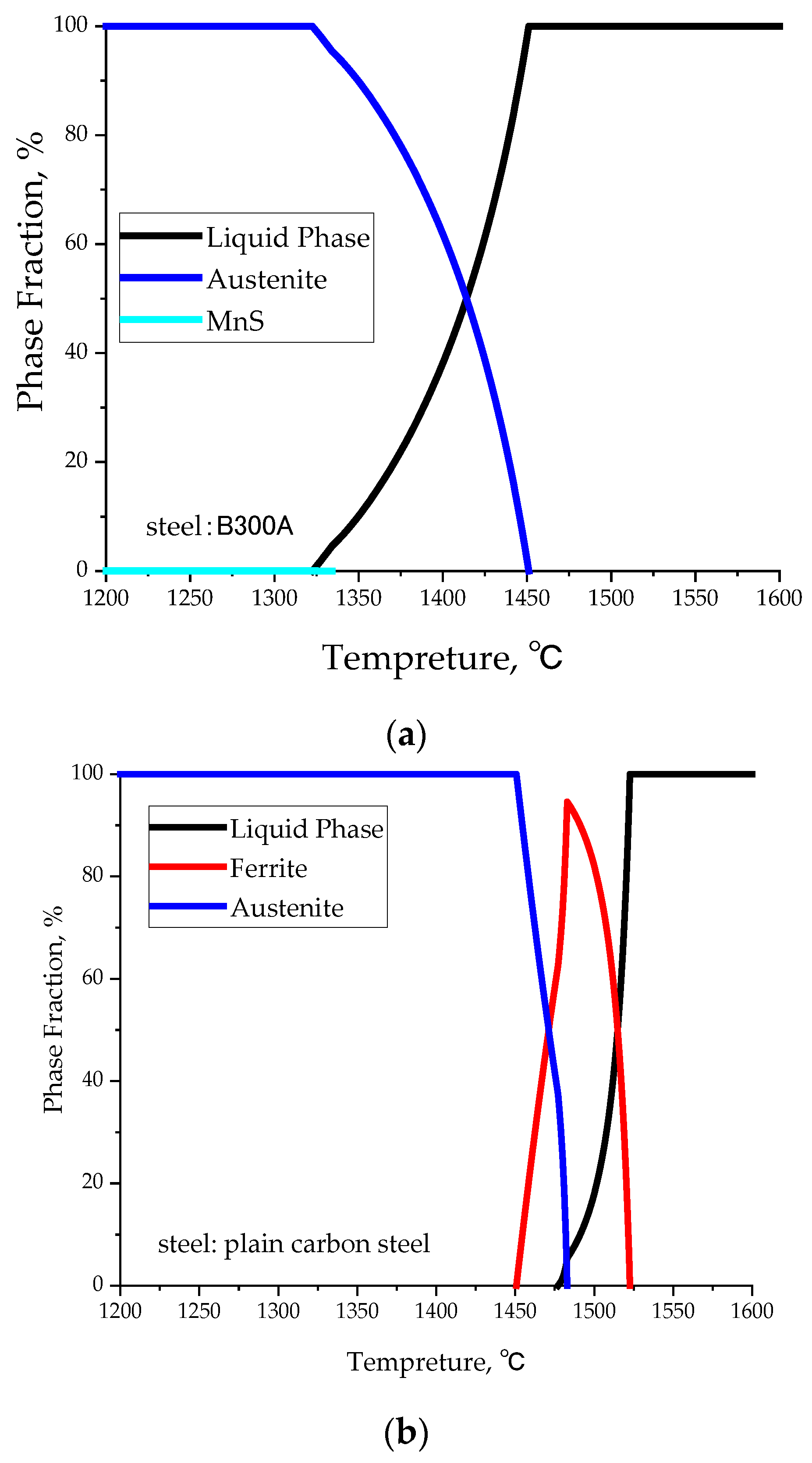
Figure 2 and Table 4 displays the solidification path, temperature of the solidified two-phase region, and volume shrinkage rate when the solid phase ratio is 80%. It is worth noting that volume shrinkage grows with an increasing solid phase ratio. The initial phase solidification is austenite with an FCC lattice due to the steel’s higher carbon content, which has a dense row structure. This leads to a more significant redistribution of solutes and poorer diffusion capacity of alloying elements during the solidification process. Furthermore, solute micro-partitioning is more severe than in the ferrite mode. Some steel grades with a higher alloy content also have a wide two-phase zone up to 140 °C, resulting in a solidification shrinkage that is 1.3 times that of plain carbon steels. The formation of a large negative pressure while pumping thickened steel causes significant contraction, leading to serious center shrinkage. This is the fundamental reason for the difficulty in controlling the quality of the center of high-carbon steel during continuous casting. In the continuous casting process, the width of the two-phase zone solidification increases with the distance from the centerline of the paste zone (TL to TS). The paste area is where solid and liquid phases coexist, and elective crystallization and solute redistribution occurs. It is important to note that the length of the paste area affects the solidification end and the negative pressure pumping of liquid steel alloy content. The longer the paste area, the higher the content of the alloy in the liquid steel, and the more significant the segregation in the center. If the liquid steel is not pumped correctly, shrinkage holes may form in the center. The wider the range of the two-phase zone, the more units of the drawing and straightening machine can be implemented under light pressure, and the regulation window is wider. To improve matrix homogeneity, it is necessary to fully consider the solidification and continuous casting characteristics of high-carbon steel from the source.
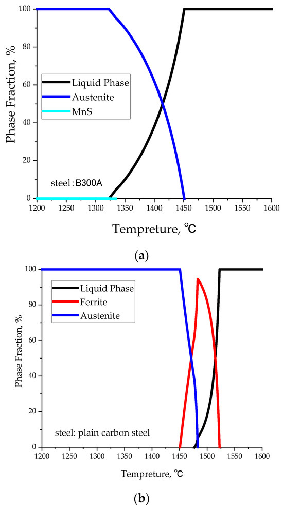
Figure 2.
Solidification path of typical high carbon alloy steel (a) B300A and (b) plain carbon steel.
Table 4.
Solidification characteristics of typical high carbon alloy steel and ordinary carbon steel.
3. Methods
3.1. Simulation Methodology
This paper analyses the use of high-carbon wear-resistant steel B300A in the continuous casting press-down process using numerical simulation technology. The temperature field and thickness of the solidified billet shell are calculated, followed by the billet stress field. The causes of billet quality defects are analyzed based on the stress and temperature fields.
- A
- Basic assumptions
Because the solidification heat transfer process of continuous casting billet is described by a three-dimensional unsteady differential equation with an internal heat source, the calculation is complicated. In order to simplify the calculation, this paper makes reasonable assumptions about the continuous casting process, and the basic assumptions of the model are as follows: Firstly, as the heat dissipation in the direction of billeting is much smaller than that in the circumferential direction of the cross-section, accounting for about 3% to 6% of the total heat, the heat transfer in the direction of billeting can be ignored, and the heat transfer of solidification can be simplified to a two-dimensional heat transfer problem; Secondly, steel is an incompressible fluid; Thirdly, we ignore the bending effect of the billet and mechanical equipment caused by relevant transmission phenomena; Fourthly, we assume uniform release of solidification latent heat in the two-phase region.
- B
- Solidification heat transfer model
According to the law of conservation of energy, the solidification heat transfer of large square billets for continuous casting is analyzed, and combined with the above assumptions, the two-dimensional unsteady state heat transfer model equation is obtained as shown in Equation (1)
In the above equation:
- λ—Thermal conductivity of cast billets, W/(m·°C);
- ρ—Billet density, kg/m3;
- C—Equivalent specific heat, J/(kg·°C);
- T—Casting temperature,·°C;
- x, y—Coordinate axis, m.
- C
- Cooling Shrinkage Model
The replenishment of solidification shrinkage by steel in the continuous casting process is related to the ratio of solid phase. Research findings suggest that when the solid phase rate exceeds the flow critical value of 0.3, dendrites connect to the veins, causing an increase in steel viscosity, resulting in poor fluidity and more difficult complementary shrinkage. When the solid phase rate exceeds the viscous critical value of 0.9, the steel almost completely stops flowing, and any shrinkage holes formed will be retained. Therefore, the calculation of theoretical shrinkage requires a statistical analysis of the solidification heat state of the continuous casting billet. This paper presents a theoretical derivation of the solidification process of a large square billet of high-carbon steel with center shrinkage. Sugimaru et al. [24] proposed a formula (Formula (2)) that considers the efficiency of engineering calculations and precision to simplify the theoretical shrinkage formula.
where is the shrinkage at the ith draw-straightener, W and Th are the width and thickness, respectively, and is the central solid phase rate at the ith draw-straightener.
3.2. Main Parameters
- A
- Structural parameters
The schematic diagram of the mathematical model for the continuous casting machine under pressure for big square billets is presented in Figure 3. Figure 3a,b represent the pressure and temperature field distributions of the cast billet, respectively. Table 5 displays the basic geometric parameters of the continuous casting machine, while Table 6 illustrates the distribution of cooling water in its five sections.
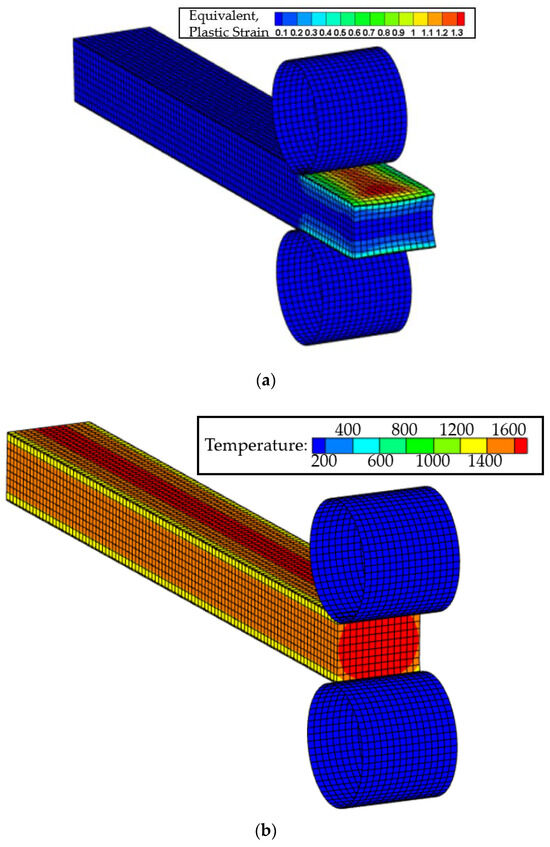
Figure 3.
Mathematical model of continuous casting under pressure. (a) The pressure field; (b) the pressure field.
Table 5.
Basic parameters of the bloom continuous caster.
Table 6.
Water distribution parameters for each subzone of the second cooling, L/min.
- B
- Process parameters for the B300A casting process
Table 7 displays the selected thermodynamic parameters for the continuous casting simulation process.
Table 7.
Process parameters for B300A casting process.
3.3. Verification of Continuous Casting Heat Transfer Mold Accuracy
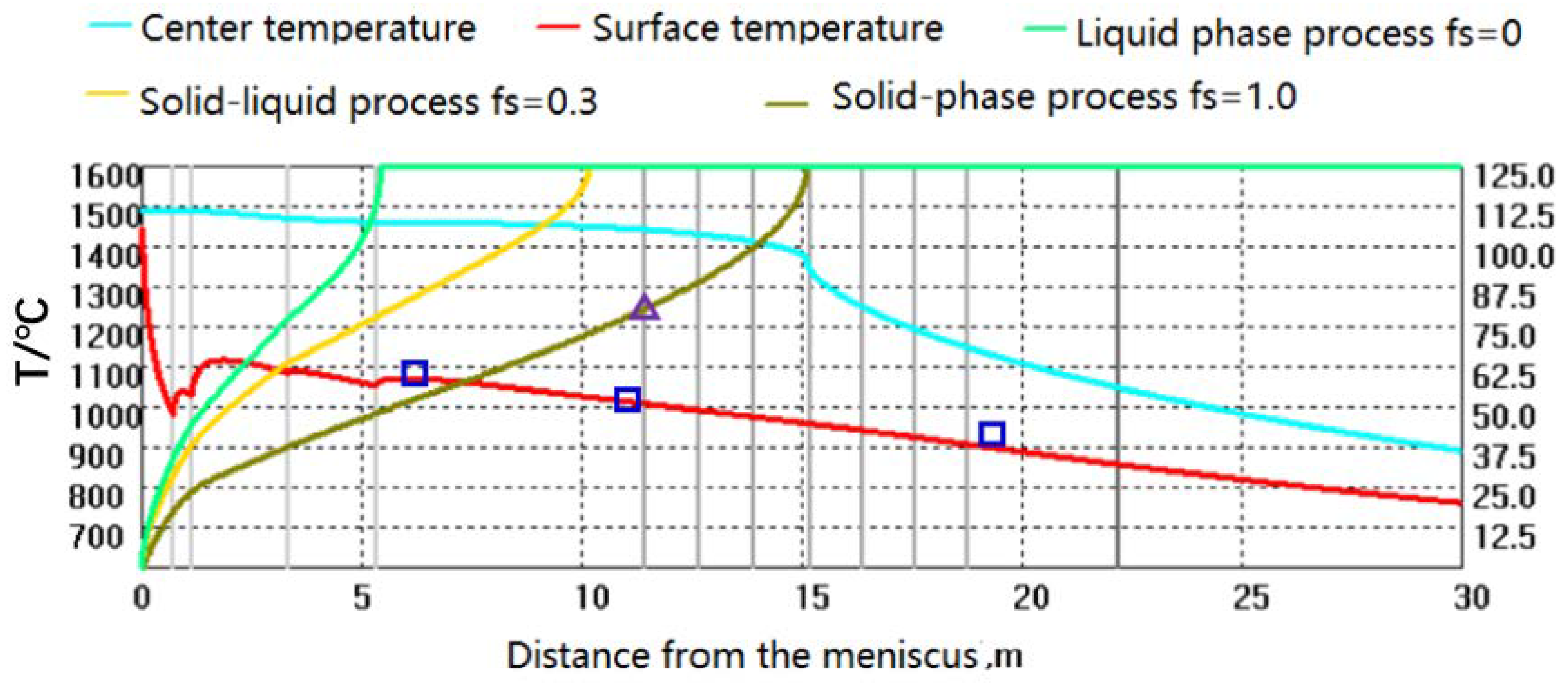
Mathematical modelling is a dependable technique for revealing the solidification process of bloom continuous casting [25,26,27]. The model, which has been validated by field data, can accurately predict the thermal state of continuous casting under different working conditions. This prediction serves as the basis for determining the process parameters under reasonable light pressure. Figure 4 displays the phase rate curves for three different frequencies: fs = 0, fs = 0.3, and fs = 1.0. The surface temperatures (hollow squares) and billet shell thicknesses (hollow triangles) of HM2 high-carbon steel were measured under various working conditions to verify the model’s predictions. The difference between the model-calculated billet surface temperature and the measured value is less than 20 °C, and the difference in billet thickness is less than 2 mm. The model validation results demonstrate that the simulation study can produce more accurate experimental results. This provides a guiding basis for subsequent industrial tests.

Figure 4.
Model prediction results and measured data.
3.4. Industrial Test Methods
In order to assess the impact of continuous casting undercutting technology on the center quality of high-carbon steel blooms, a sampling scheme was developed as shown in Figure 5. To evaluate solute segregation, 5–10 transverse specimens were continuously cut along the direction of billet pulling. Furthermore, a longitudinal specimen with a length of 500 mm was cut for low-fold detection. The billet surface was acid-washed to check for cracks and depressions. A φ4 mm drill was used to extract a ‘米’-shaped chip sample from the transverse specimen. The carbon content was determined using a carbon and sulfur analyzer. It is important to note the volatility of billet center segregation and shrinkage. The carbon content of 63 chip samples taken from the transverse specimen using a φ4 mm drill bit was determined using a carbon and sulfur analyzer.
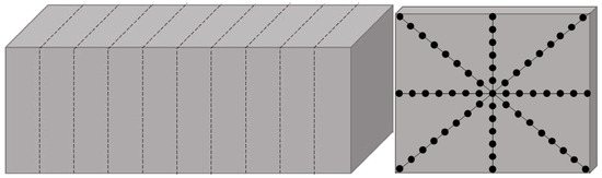
Figure 5.
Sampling locations for low doubling and carbon segregation in high carbon steel continuous casting billets.
4. Simulation Results and Discussion
4.1. Influence of Key Process Parameters on the End of Solidification
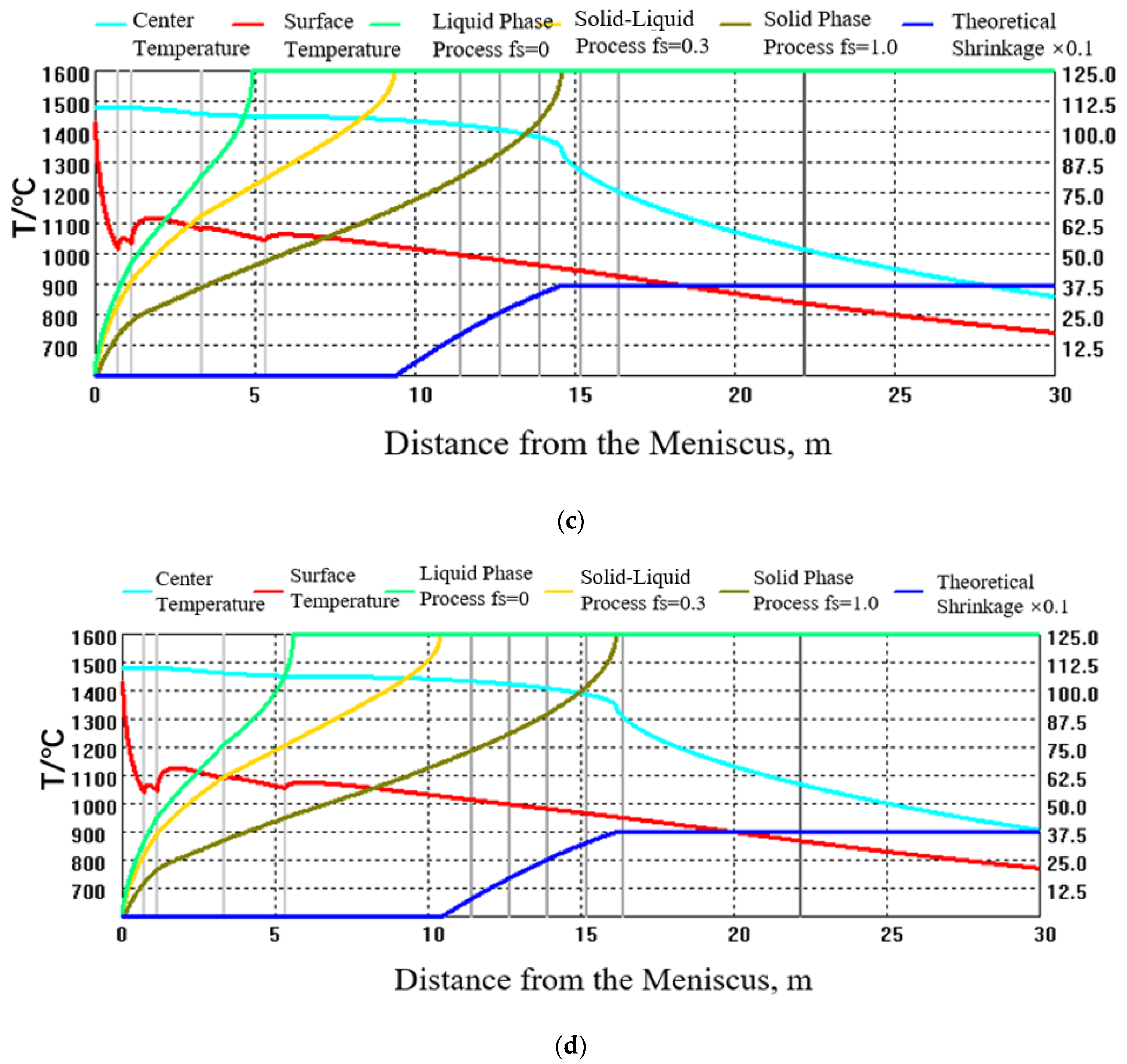
A simulation study was conducted on the solidification characteristics of the 250 mm × 280 mm big square solidification process and the shrinkage change rule of law under different process conditions, based on the big square billet continuous casting solidification heat transfer model and cooling contraction model. Figure 6 illustrates the solidification characteristics under different pulling speed conditions. When the pulling speed is less than or equal to 0.47 m/min, the solidification endpoint occurs before the pressable unit of the drawing and straightening machine. As a result, the liquid core length is too small to compensate for the solidification shrinkage by soft pressing down, and the theoretical shrinkage is 6.55 mm2. When the pulling speed is 0.52 m/min, the solidification endpoint occurs between the number two and number three drawing and straightening machines. At this point, two to three rolls of soft pressing down can be carried out, and the theoretical shrinkage is six. At a pulling speed of 0.57 m/min, the solidification end point falls between the number three and number four drawing and straightening machines. At this point, it is possible to carry out three to four rolls of soft pressing down, resulting in a theoretical shrinkage of 6.86 mm2. If the pulling speed exceeds 0.62 m/min, the solidification end point approaches the number five drawing and straightening machine. At this point, it is possible to carry out four to five rolls of sot pressing down, resulting in a theoretical shrinkage of 6.98 mm2. For optimal billet center quality, the drawing speed should be no less than 0.47 m/min.
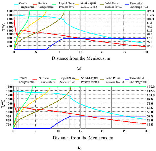
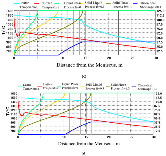
Figure 6.
Solidification process of B300A continuous casting under different drawing speeds: (a) 0.47 m/min, (b) 0.52 m/min, (c) 0.57 m/min, (d) 0.62 m/min.
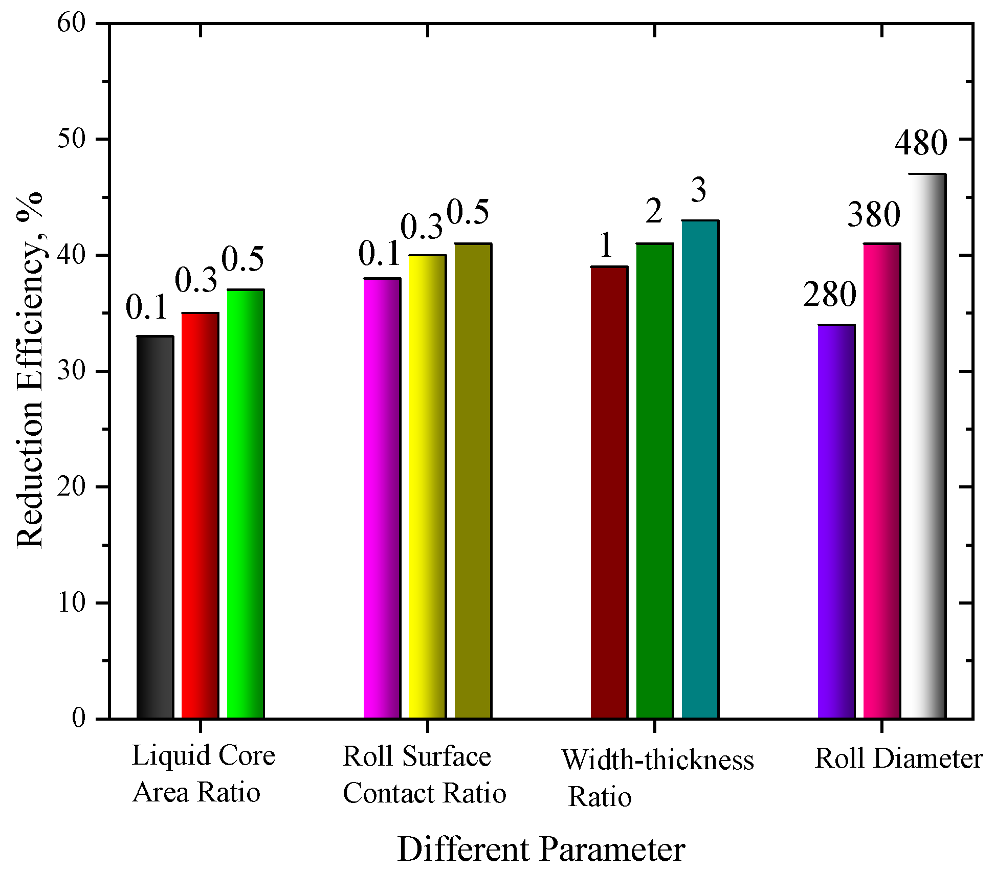
Reduction efficiency is a crucial factor for determining the effectiveness of pressing implementation [28]. If the efficiency is too low, it may lead to an increase in central deformation and the potential occurrence of reduction cracks. Conversely, if it is excessively high, it may result in insufficient central deformation, thereby failing to effectively address defects such as segregation and shrinkage. The study investigated the effects of liquid core area ratio, mill contact ratio, width-to-thickness ratio, and rolling diameter on the undercutting efficiency in the continuous casting process of 250 mm × 280 mm large-size billet high-carbon steel, based on the formula proposed by Ito [28]. Figure 7 shows that as the liquid core area ratio, roll surface contact ratio, and width-thickness ratio increase, the reduction efficiency also increases. Additionally, increasing the rolling diameter significantly increases the reduction efficiency. Generally, the soft pressing efficiency of the continuous casting billet under conventional conditions ranges from 35% to 45%. However, in actual production, different steel grades, sections, and process conditions can result in varying theoretical shrinkage amounts, reduction efficiencies, and apparent reduction amounts. Therefore, it is crucial to establish accurate reduction process parameters based on the solidification characteristics of continuous casting.

Figure 7.
Effect of different parameters on efficiency at soft pressure.
4.2. Evaluation of Soft-Pressure Process Parameters Considering Factors Affecting Depression Efficiency
A process model for the soft reduction of a 250 mm × 280 mm large-sized billet has been established, taking into account the calculation of solidification shrinkage between neighboring drawing machines and the influence of liquid core area ratio, roll surface contact ratio, width-to-thickness ratio, and roll diameter on reduction efficiency. The process parameters for B300A high-carbon steel under different drawing speeds have been designed, including basic process parameters, total reduction, and reduction distribution, as shown in Table 8. The pulling speed of 0.52 m/min resulted in a large reduction amount for rolls number one and number two, which cannot be compensated for solidification shrinkage. Additionally, the equipment cannot meet this speed. At a speed of 57 m/min, the distribution of solidification shrinkage is more reasonable, and the reduction amount for rolls one to three can be set to 3.1 mm, 4.2 mm, and 5.0 mm, respectively. At a pulling speed of 0.62 m/min, the reduction amount for rolls one to four can be set to 1.1 mm, 4.2 mm, and 5.0 mm, respectively. Due to the high-carbon alloy composition of wear-resistant steel, it has a tendency towards solidification shrinkage. To compensate for this, a larger rate of reduction is used to improve deformation permeability. In this case, a pulling rate of 0.57 m/min and its corresponding reduction parameters were selected for the industrial test program.
Table 8.
Process parameters for B300A under soft reduction.
4.3. Influence of Continuous Casting Heavy Reduction Process on Casting Billet Quality
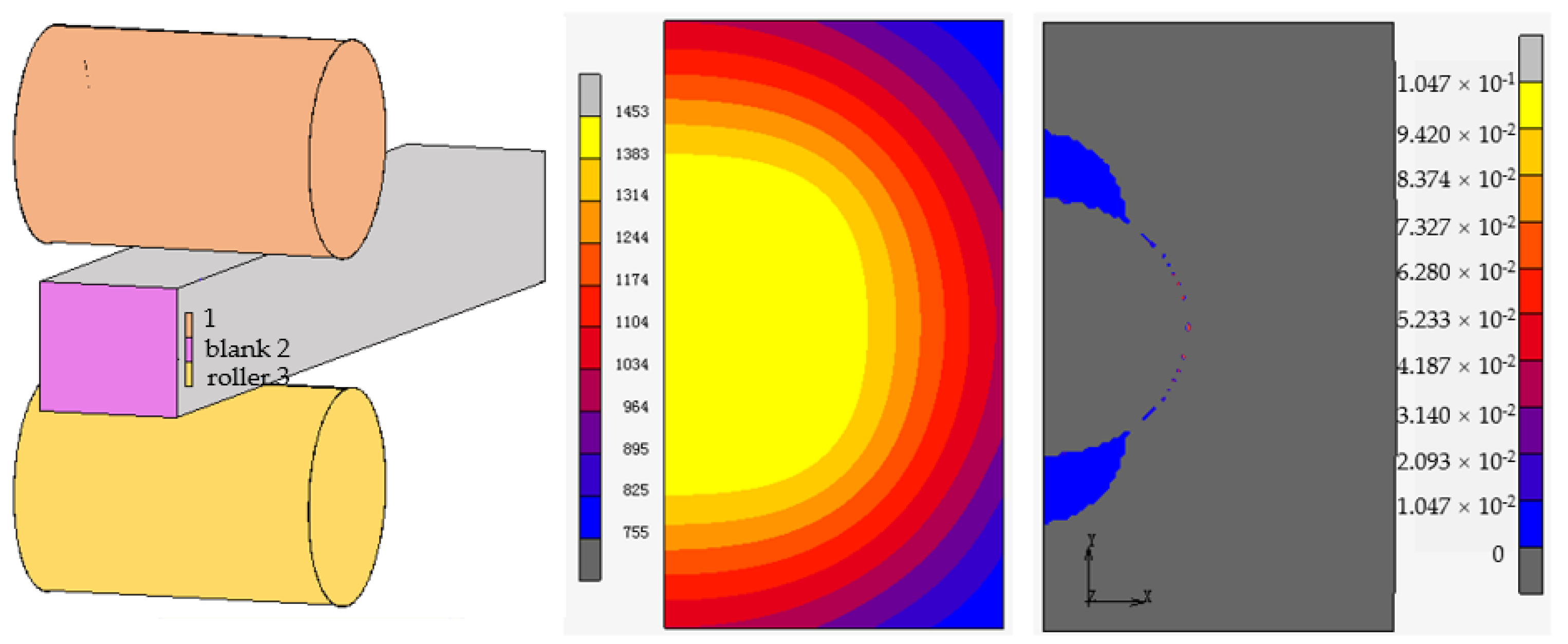
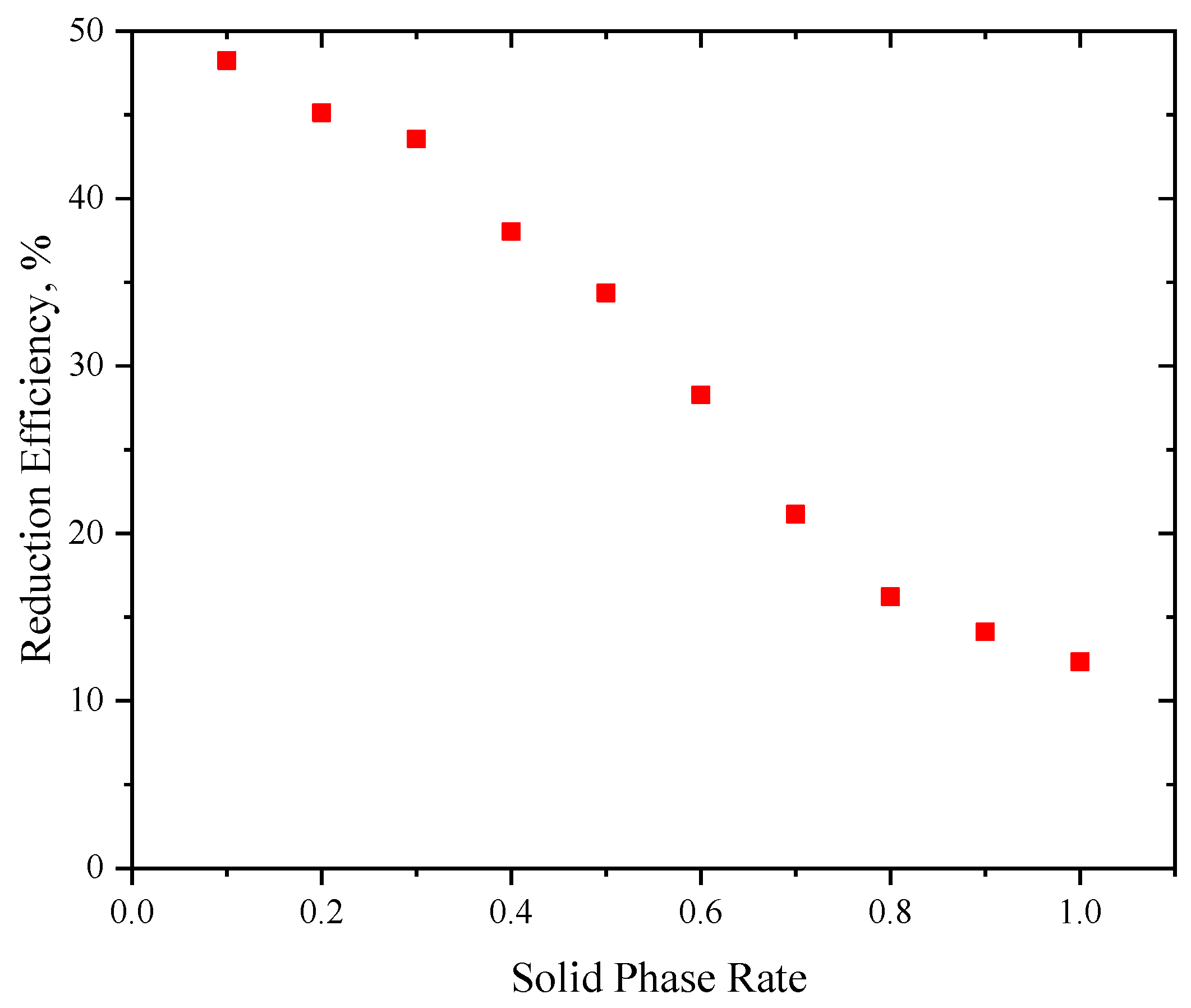
The issues of center segregation and shrinkage in high-carbon steel continuous casting are primarily linked to solidification shrinkage. Although the application of soft pressure has significantly enhanced the quality of the center in high-carbon steel 250 mm × 280 mm large square billets, there still remains a level 1.0 sparsity and shrinkage in the center, and a level 1.5 V-type segregation. In order to meet the GB/T4162A [29] level of flaw detection requirements for bars with a diameter of ≥φ70 mm, it is necessary to cooperate with the long high temperature diffusion time and high compression ratio rolling of the casting billet. This process can affect production efficiency and the casting of billets when expanding the specifications of material production [30]. Based on the continuous casting solidification cooling contraction model established previously, a large square billet process model under heavy pressure was developed. The model takes into account the austenite volume contraction after cumulative solidification and the size of the shrinkage holes left behind under the soft pressure of 0.5–1.0 mm, as shown in Figure 8. The purpose of this model is to predict the theoretical cumulative reduction and single-roll reduction required to completely weld together shrinkage holes under heavy pressing. At heavy reduction, the billet is fully solidified, so it is necessary to evaluate the difference between the reduction efficiency and the solid phase rate to clarify the characteristics of heavy and soft reduction. Figure 9 shows that when the billet is fully solidified, with a central solid phase rate of 1, the reduction efficiency is between 10% and 15%. This is approximately one-quarter to one-third of the efficiency of soft reduction when the solid phase rate is 0.3.

Figure 8.
The finite element model and its temperature field and strain distribution in 1/2 of the region of reduction deformation at the solidification end of bloom continuous casting.
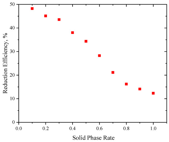
Figure 9.
Pressing efficiency of large square billet continuous casting with different solid phase ratios.
The implementation process of heavy reduction can directly impact the distribution of alloying elements at the center of the casting billet [31]. As shown in Figure 10, when applied under heavy pressure after solidification, the main deformation is concentrated in the high temperature area of the core of the continuous casting billet because of the characteristics of being hot before and cold after solidification, and hot outside and cold inside the continuous casting billet. After solidification, the temperature at the center of the region decreases rapidly, causing a rapid increase in strength and resistance to deformation. Plastic rheology is affected by a heavy reduction in the opposite direction of pulling speed. This means that the high-temperature ‘fluid’ at the center is forced to the direction of the meniscus. Due to the large deformation, the solid liquid phase zone of casting billet’s center will be squeezed, resulting in a concentration of dendritic crystals. The steel between the dendritic crystals flows into the liquid phase cavity at the front end, resulting in forced solidification there. Selective crystallization can cause negative segregation during solidification. This happens because the solid phase dendrites have a low solute content, while the liquid phase between the dendrites has a high solute content. As a result, heavy pressure pushes the liquid steel into the liquid-phase cavity, leaving the solid phase with insufficient solute content on average. In particular, the electromagnetic stirring at the end homogenizes the concentrated steel, weakening the solute enrichment between the dendrites and resulting in more significant negative segregation under heavy-pressure conditions. To improve the quality of cast billets, it may be important to use both soft and heavy reduction processes together.
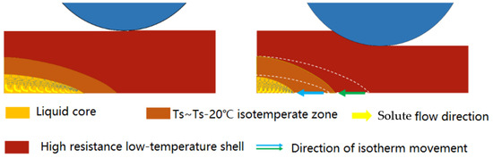
Figure 10.
Mechanism of negative segregation in central region under heavy pressure in continuous casting.
5. Industrial Tests under Soft and Heavy Mixed Pressure in Continuous Casting
5.1. Experimental Methods
Table 9 presents an analysis of the solidification process, theoretical shrinkage, and unit apparent reduction of the drawing and straightening machine of high carbon steel at different drawing speeds, based on the previously established soft and heavy reduction models. Increasing the pulling speed from 0.48 m/min to 0.63 m/min leads to an increase in liquid core length from 11.5 m to 16.2 m. To ensure that both soft and heavy pressure can be applied simultaneously, the end of the solidification must fall within the range of the tension leveler unit. Therefore, a pulling speed of less than 0.48 m/min is unsuitable. At a pulling speed of 0.53 m/min, the executive racks for soft reduction are number one and number two. The theoretical reduction for both racks exceeds the rated value. The compensation for reduction can be optimized for the subsequent tension leveler. The three to seven tension leveler can perform heavy reduction, with a reduction of 5.0 mm, 5.0 mm, 5.0 mm, and 3.0 mm. The one to three tension leveler can perform soft reduction to execute the desired amount of press down at pulling speeds of 0.58 m/min, but the preset value of the number three machine exceeds the rated value. The numbers four the seven tension levelers can perform heavy reductions, with reduction amounts of 4.0 mm, 4.0 mm, 3.0 mm, and 3.0 mm respectively. When the tension speed is 0.63 m/min, the tension levelers from one to four can perform light reductions, with reduction amounts close to the set value of 2.0 mm, 3.0 mm, 5.0 mm, and 5.0 mm, respectively. The tension levelers from 5 to 7 also perform heavy reductions, with reduction amounts of 5.0 mm, 3.0 mm, and 3.0 mm respectively. The drawing and straightening machine applies significant pressure during different operations, with 5.0 mm, 3.0 mm, and 3.0 mm of force. The comparison indicates that as the pulling speed increases, the reduction distribution gradually matches the equipment capacity. We have developed a 250 mm × 280 mm high carbon bloom billet for soft and heavy mixed reduction testing with a pulling speed of 0.63 m/min, based on the previous results of the soft under pressure test and considering the matching problem between the furnace and the machine.
Table 9.
Process parameters of heavy and soft mixed reduction for high carbon steel.
5.2. Results
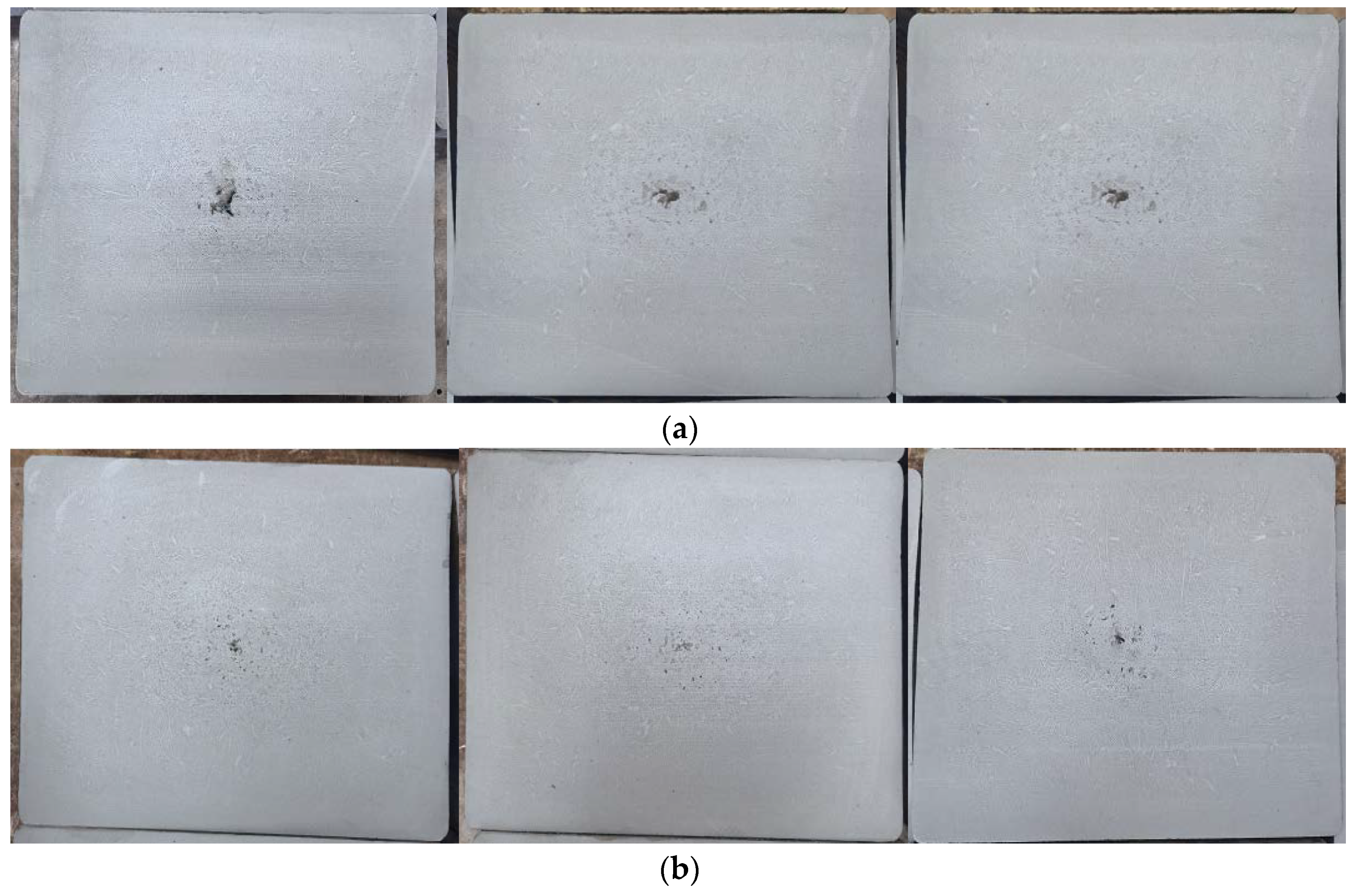
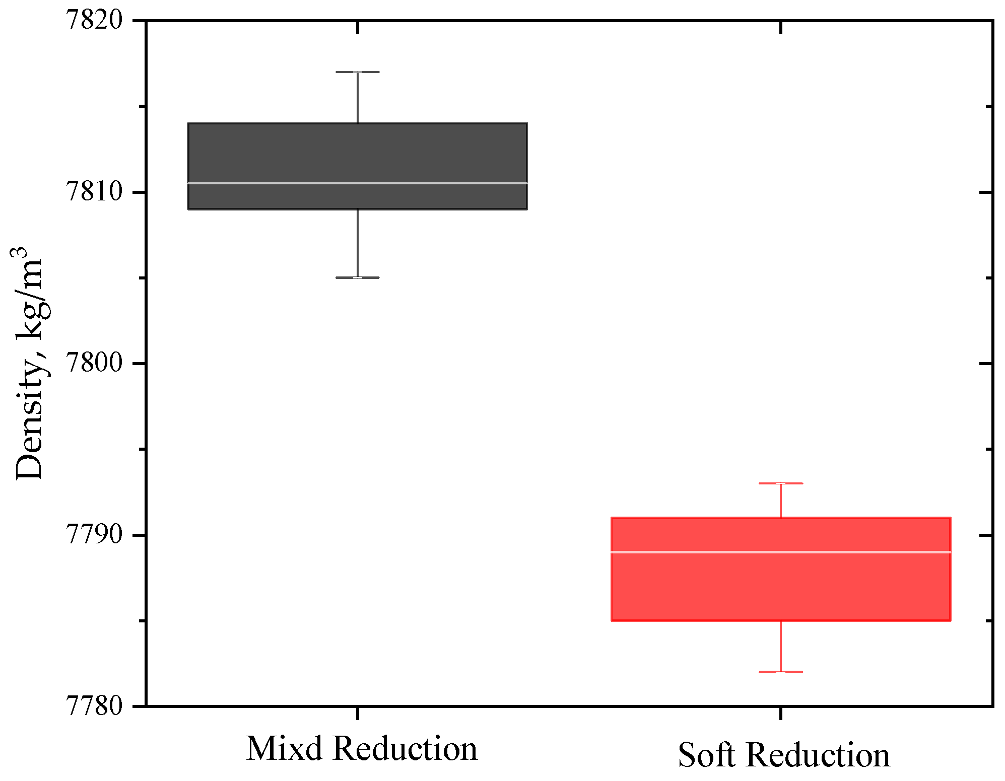
Figure 11 shows that the center segregation and shrinkage ratings of the cast billet reached 0~0.5, and the center sparsity improved to 0.5~1.0 when mixed soft and heavy reduction was used, which is 0.5~1.0 higher than when only soft reduction was used. The density inspection results of the center region of the continuous casting billet were compared between soft and mixed soft and heavy reduction. Figure 12 shows that after applying hybrid reduction, in situ analysis was used to examine the matrix core densities. The average density increased from 92.82% to 93.52%, an increase of 0.7%. This increase is due to the high efficiency of compensating for center shrinkage under heavy reduction [32]. Figure 13 displays the results of carbon segregation under different reduction conditions. There is an obvious positive effect on the enrichment of carbon solutes in the central region by applying soft and heavy reduction. This results in a reduction of the center segregation ratio from 1.27 to 1.08, center deviation control in the range of 0.95~1.08, meeting all overall product control requirements.
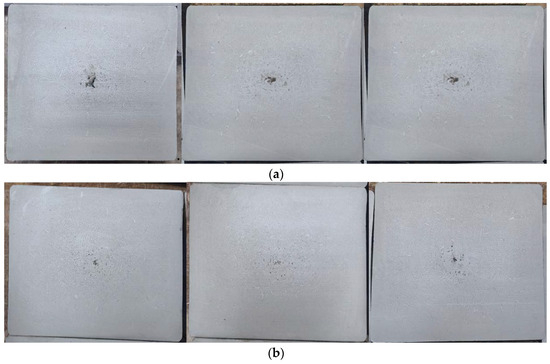
Figure 11.
Low power contrast of B300A before and after soft reduction: (a) normal reduction, (b) soft–heavy combined reduction.

Figure 12.
The density of the matrix in the central region of the continuous casting billet varies with the casting process.
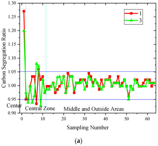
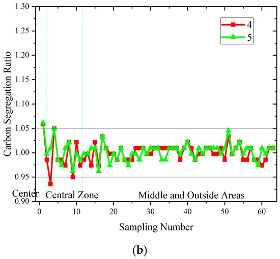
Figure 13.
Segregation index of B300A before and after soft reduction: (a) normal reduction, (b) soft–heavy combined reduction.
6. Conclusions
(1) A mathematical model revealing the solidification process of large billet continuous casting is proposed, and the model is validated using field data with high accuracy. The mathematical model can better predict the process of continuous casting.
(2) Based on the numerical simulation, the effect of different pulling speeds on the solidification process is revealed, and the pulling speed should not be less than 0.47 m/min; this can effectively improve the center quality of bloom. Furthermore, the difference of reduction efficiency under heavy reduction and soft pressure was evaluated. At heavy reduction, when the billet is fully solidified, with a central solid phase rate of 1, the reduction efficiency is between 10% and 15%. This is approximately one-quarter to one-third of the efficiency of soft reduction when the solid phase rate is 0.3.
(3) The center segregation and shrinkage of the casting bloom were improved to a level of 0.5~1.0 by the mixed treatment of soft and heavy reduction compared to soft reduction alone. Also, the matrix core density was improved by 0.7%. After the mixed soft and heavy reduction treatment in the center of the carbon solute-rich zone, the center segregation was reduced from 1.27 to 1.08, resulting in the overall achievement of product control requirements.
Author Contributions
A.D.: design and completion of the experiment, and analysis of characterization, data processing, chart drawing, manuscript writing, and delivery; M.W.: writing—review and editing; H.W.: support for testing, support for manuscript writing; X.F.: provision of raw materials, review of manuscripts; W.L.: review of manuscripts. All authors have read and agreed to the published version of the manuscript.
Funding
This research was funded by National Natural Science Foundation of China, grant number 52374320.
Data Availability Statement
The original contributions presented in the study are included in the article, further inquiries can be directed to the corresponding author.
Conflicts of Interest
Aiguo Dang, Haida Wang and Xiaoming Feng were employed by the Jianlong Beiman Special Steel Co., Ltd. The remaining authors declare that the research was conducted in the absence of any commercial or financial relationships that could be construed as a potential conflict of interest.
References
- Ren, J.; Mao, D.; Gao, Y.; Chen, J.; Liu, Z.Y. High carbon alloyed design of a hot-rolled high-Mn austenitic steel with excellent mechanical properties for cryogenic application. Mater. Sci. Eng. A 2021, 827, 141959. [Google Scholar] [CrossRef]
- Gao, Y.; Bao, Y.; Wang, M.; Zhang, M. On the Macrosegregation of Continuous Casting of High Carbon Steel Billet with Strand Reduction Process. Metals 2024, 14, 157. [Google Scholar] [CrossRef]
- Dou, K.; Yang, Z.; Liu, Q.; Huang, Y.; Dong, H. Influence of secondary cooling mode on solidification structure and macro-segregation behavior for high-carbon continuous casting bloom. High Temp. Mater. Process. 2017, 36, 741–753. [Google Scholar] [CrossRef]
- Ludlow, V.; Normanton, A.; Anderson, A.; Thiele, M.; Ciriza, J.; Laraudogoitia, J.; Van Der Knoop, W. Strategy to minimise central segregation in high carbon steel grades during billet casting. Ironmak. Steelmak. 2005, 32, 68–74. [Google Scholar] [CrossRef]
- Senuma, T.; Okayasu, M.; Mohrbacher, H. Microstructural Control and Alloy Design for Improving the Resistance to Delayed Fracture of Ultrahigh-Strength Automotive Steel Sheets. Metals 2023, 13, 1368. [Google Scholar] [CrossRef]
- Ludwig, A.; Wu, M.; Kharicha, A. On macrosegregation. Metall. Mater. Trans. A 2015, 46, 4854–4867. [Google Scholar] [CrossRef]
- Ueshima, Y.; Mizoguchi, S.; Matsumiya, T.; Kajioka, H. Analysis of solute distribution in dendrites of carbon steel with δ/γ transformation during solidification. Metall. Trans. B 1986, 17, 845–859. [Google Scholar] [CrossRef]
- Clyne, T.; Wolf, M.; Kurz, W. The effect of melt composition on solidification cracking of steel, with particular reference to continuous casting. Metall. Trans. B 1982, 13, 259–266. [Google Scholar] [CrossRef]
- ZoNg, N.; JiNg, T.; Liu, Y. Comparative studies on a chamfer technology and a convex roll technology during the soft reduction process. Arch. Metall. Mater. 2021, 66, 819–829. [Google Scholar] [CrossRef]
- Han, Y.; Yan, W.; Zhang, J.; Chen, J.; Chen, W.; Liu, Q. Comparison and integration of final electromagnetic stirring and thermal soft reduction on continuous casting billet. J. Iron Steel Res. Int. 2021, 28, 160–167. [Google Scholar] [CrossRef]
- Li, X.; Ding, H.; Tang, Z.; He, J. Formation of internal cracks during soft reduction in rectangular bloom continuous casting. Int. J. Min. Met. Mater. 2012, 19, 21–29. [Google Scholar] [CrossRef]
- Brimacombe, J. The challenge of quality in continuous casting processes. Metall. Mater. Trans. A 1999, 30, 1899–1912. [Google Scholar] [CrossRef]
- Moon, C.; Oh, K.; Lee, J.; Lee, S.; Lee, Y. Effect of the roll surface profile on centerline segregation in soft reduction process. ISIJ Int. 2012, 52, 1266–1272. [Google Scholar] [CrossRef]
- Yim, C.; Park, J.; You, B.; Yang, S. The effect of soft reduction on center segregation in CC slab. ISIJ Int. 1996, 36, S231–S234. [Google Scholar] [CrossRef] [PubMed]
- Thome, R.; Harste, K. Principles of billet soft-reduction and consequences for continuous casting. ISIJ Int. 2006, 46, 1839–1844. [Google Scholar] [CrossRef]
- Liu, K.; Sun, Q.; Zhang, J.; Wang, C. A study on quantitative evaluation of soft reduction amount for CC bloom by thermo-mechanical FEM model. Metall. Res. Technol. 2006, 113, 504. [Google Scholar] [CrossRef]
- Chen, Y.; Li, G.; Yang, S.; Zhu, M. Dynamic soft reduction for continuously cast rail bloom. J. Iron Steel Res. Int. 2007, 14, 13–17. [Google Scholar] [CrossRef]
- Ali, N.; Zhang, L.; Sui, Z.; Zhou, H.; Zhang, C.; Nian, Y. Spatial Characterization of Internal Defects in Medium Carbon Steel via X-Ray Computed Tomography. Steel Res. Int. 2022, 93, 2100777. [Google Scholar] [CrossRef]
- Nabeshima, S.; Nakato, H.; Fujii, T.; Fujimura, T.; Kushida, K.; Mizota, H. Control of centerline segregation in continuously cast blooms by continuous forging process. ISIJ Int. 1995, 35, 673–679. [Google Scholar] [CrossRef]
- Kawamoto, M. Recent development of steelmaking process in Sumitomo metals. J. Iron Steel Res. Int. 2011, 18, 28–35. [Google Scholar]
- Ji, C.; Li, G.; Wu, C.; Zhu, M. Design and application of CSC-roll for heavy reduction of the bloom continuous casting process. Metall. Mater. Trans. B 2019, 50, 110–122. [Google Scholar] [CrossRef]
- Dong, Q.; Zhang, J.; Wang, B.; Zhao, X. Shrinkage porosity and its alleviation by heavy reduction in continuously cast strand. J. Mater. Process. Technol. 2016, 238, 81–88. [Google Scholar] [CrossRef]
- Zhao, X.; Zhang, J.; Lei, S.; Wang, Y. Finite-element analysis of porosity closure by heavy reduction process combined with ultra-heavy plates rolling. Steel Res. Int. 2014, 85, 1533–1543. [Google Scholar] [CrossRef]
- Sugimaru, S.; Nakashima, J.; Miyazawa, K.; Ogibayashi, S. Theoretical analysis of the suppression of solidification shrinkage flow in continuously cast steel blooms. Mater. Sci. Eng. A 1993, 173, 305–308. [Google Scholar] [CrossRef]
- Yang, B.; Zhang, H.; Wang, M. Modelling of continuous casting processes parameters on the shrinkage cavity formation in bearing steel blooms. Ironmak. Steelmak. 2023, 50, 1169–1180. [Google Scholar] [CrossRef]
- Avatar, K.; Mazumdar, D.; Agnihotri, A. Considerations Concerning Numerical Modelling of Flow and Heat Transfer Phenomena in Continuous Casting of Steel. ISIJ Int. 2023, 63, 596–600. [Google Scholar] [CrossRef]
- Wang, Z.; Wang, E.; Fautrelle, Y.; Zhai, Z. Numerical Simulation of Melt Flow, Heat Transfer and Solidification in Final Solidification Zone of Bloom Continuous Casting with Vertical Linear Electromagnetic Stirring. Metall. Mater. Trans. A 2024, 55, 1482–1496. [Google Scholar] [CrossRef]
- Ito, Y.; Yamanaka, A.; Watanabe, T. Internal reduction efficiency of continuously cast strand with liquid core. Metall. Res. Technol. 2000, 97, 1171–1176. [Google Scholar] [CrossRef]
- GB/T 4162-2022; Forged and Rolled Steel Bars—Method for Uitrasonic Testing. State Administration for Market Regulation: Beijing, China, 2022.
- Li, R.; Li, H.; Wang, L.; Wang, G.; Li, J.; Li, J. Influence of hot-core heavy reduction rolling on microstructure uniformity of casting billet. Ironmak. Steelmak. 2023, 50, 273–285. [Google Scholar] [CrossRef]
- Huang, B.; Hung, F. Effect of High Temperature and Thermal Cycle of 4043 Al Alloy Manufactured through Continuous Casting Direct Rolling. Materials 2023, 16, 7176. [Google Scholar] [CrossRef] [PubMed]
- Jiang, M.; Yao, T.; Yang, E.; Wang, X. Decreasing central porosities in a continuous casting thick slab by heavy mechanical reduction near the solidification end. Metall. Mater. Trans. B 2022, 53, 3322–3333. [Google Scholar] [CrossRef]


Disclaimer/Publisher’s Note: The statements, opinions and data contained in all publications are solely those of the individual author(s) and contributor(s) and not of MDPI and/or the editor(s). MDPI and/or the editor(s) disclaim responsibility for any injury to people or property resulting from any ideas, methods, instructions or products referred to in the content. |
© 2024 by the authors. Licensee MDPI, Basel, Switzerland. This article is an open access article distributed under the terms and conditions of the Creative Commons Attribution (CC BY) license (https://creativecommons.org/licenses/by/4.0/).