Article

Finite Element Simulation and Experimental Study of U-Bending Forming of High-Strength Mg-Gd-Y-Zn-Zr Alloy

1
Education Ministry Key Laboratory of Advanced Forging & Stamping Technology and Science, Yanshan University, Qinhuangdao 066004, China
2
State Key Laboratory of Metastable Materials Science and Technology, Yanshan University, Qinhuangdao 066004, China
*
Author to whom correspondence should be addressed.
Metals 2023, 13(8), 1477; https://doi.org/10.3390/met13081477
Submission received: 29 June 2023 / Revised: 11 August 2023 / Accepted: 14 August 2023 / Published: 16 August 2023
(This article belongs to the Special Issue Metal Plastic Deformation and Forming)

Abstract

:
In this study, the constitutive equation of the high-strength Mg-Gd-Y-Zn-Zr alloy sheet was established by tensile tests at different temperatures and different tensile rates. The U-shape bending forming process of the sheet was simulated under different process conditions by the DEFORM software. The variation rules of the stress field, strain field and free bending force of the formed parts were analyzed, and the accuracy of the finite element simulation was verified by the U-shaped bending test. Studies have shown that the equivalent stress, equivalent strain and free bending force decreased with the increase in forming temperature. With an increase in the stamping speed, the equivalent stress and free bending force increased, while the equivalent strain did not change significantly. Notably, the maximum difference in the free bending force between the test and simulation was less than 10%. The results of this study can provide guidance for the stamping forming of high-strength Mg-Gd-Y-Zn-Zr alloy sheets.

1. Introduction

Magnesium alloys have high specific strength and excellent electromagnetic shielding performance; in addition, they are lightweight. They are widely used in high-tech fields such as aerospace vehicles, military, and national defense [1,2]. The stamping process is one of the basic processes used for material processing, and it has the advantages of high production efficiency, high material utilization rate, and good product consistency; furthermore, it can be easily mechanized and automated. It has been widely used in industrial production [3,4,5]. At the same time, stamping parts made of high-strength magnesium alloy are thin, uniform, lightweight, and strong. Therefore, the use of the stamping process to manufacture high-strength magnesium alloy ready-to-use parts can replace the machined parts to a certain extent, and has broad prospects in engineering applications [6,7,8].
Zhang et al. [9] repeatedly conducted unidirectional bending tests on the AZ31B magnesium alloy to study its effect on the cold stamping formability of magnesium alloy sheets. Han et al. [10] studied the effects of the V-bending process and continuous bending process on the microstructure, mechanical properties, and formability of an AZ31 magnesium alloy sheet. Studies have shown that V-bending and continuous bending processes can effectively improve the mechanical properties and formability of materials. Wang et al. [11] systematically studied the formability of an AZ31B magnesium alloy sheet. At the same time, an accurate numerical model of magnesium alloy warm forming was established, and a composite forming limit diagram was constructed to intuitively reflect the anisotropy of the material. Chen et al. [12] studied the formability of a stamped AZ31 magnesium alloy sheet under high-temperature conditions. The results showed that when the sheet was heated above 200 °C, the yield stress of the material was significantly reduced, showing good high-temperature formability. At present, the research of magnesium alloy sheet bending process is mainly focused on the AZ series magnesium alloy, and most of the research is the AZ31 magnesium alloy, while the research of rare earth magnesium alloy is less prominent [13,14].
While AZ series magnesium alloys have many advantages, they also have shortcomings, including low strength, unstable quality, and poor heat resistance, and the addition of rare-earth elements can improve their performance significantly [15,16,17]. Therefore, researchers have developed a large number of Mg-Gd-, Mg-Y-, Mg-Nd-based magnesium alloys. The high-strength Mg-Gd-Y-Zn-Zr alloy is a typical rare-earth magnesium alloy, which is currently being studied. Research in the field of forming has mainly focused on smelting forming, die-casting, and forging forming. However, the research on sheet metal stamping has not been reported [18,19,20,21,22].
In this study, a constitutive equation based on the deformation of the Mg-Gd-Y-Zn-Zr alloy under tensile stress was established. By simulating and testing the U-bending process of a high-strength Mg-Gd-Y-Zn-Zr alloy sheet, the U-bending law of high-strength Mg-Gd-Y-Zn-Zr alloy was studied.

2. Finite Element Simulation of U-Bending of High-Strength Mg-Gd-Y-Zn-Zr Alloy

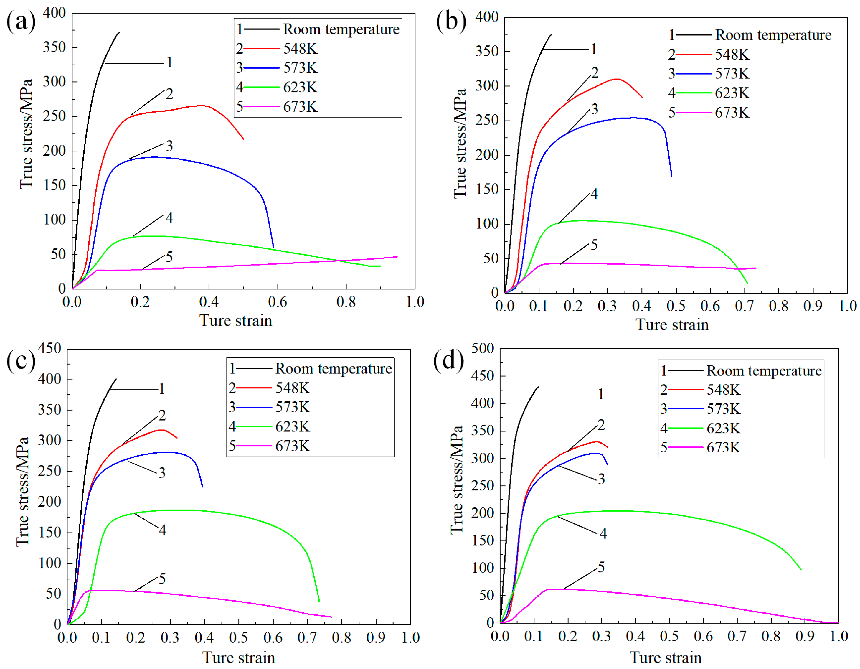
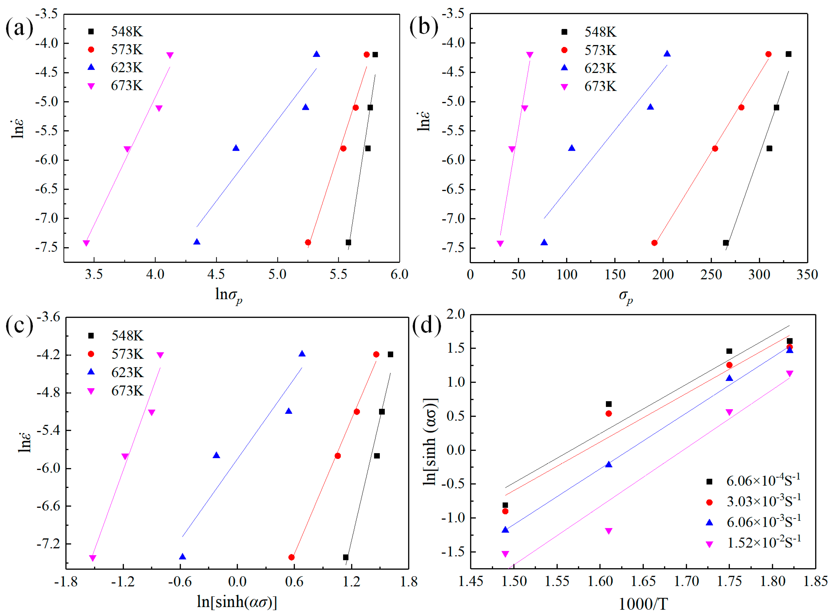
2.1. Construction of Constitutive Equation

Figure 1 shows the true stress–strain curves of high-strength Mg-Gd-Y-Zn-Zr alloy under different tensile deformation conditions. From the room temperature tensile conditions, the tensile strength of the Mg-Gd-Y-Zn-Zr alloy exceeds 300 MPa at different strain rates, and the tensile strength increases with the increase in strain rate, which is 372, 375, 401, 430 MPa, respectively. Therefore, the Mg-Gd-Y-Zn-Zr alloy can be defined as a high-strength magnesium alloy.
Under the condition of warm deformation, the strain rate has a great influence on the stress–strain curve of magnesium alloy. It can be seen from Figure 1 that the stress level of the material increases with the increase in strain rate. At the same time, the stress–strain curves at different strain rates show obvious recrystallization softening characteristics. In this regard, the hyperbolic sine equation proposed by Sellars [14,15] can be used to express the relationship between the flow stress of the material and the strain rate and temperature during the deformation process, as shown in Formula (1),
ε ˙ = A sinh α σ n exp Q / R T
where ε ˙ is strain rate (s−1); σ is stress (MPa); A and n are material constants; Q is hot deformation activation energy (J/mol); T is the absolute temperature (K); R is the gas constant, R = 8.314 J/(mol·K).
In this study, the peak stress was used as the basis for the construction of the constitutive model of high-strength Mg-Gd-Y-Zn-Zr alloy. Figure 2 shows the linear regression curve of each related parameter. Combined with the slope and intercept of the regression curve in the diagram, the relevant parameters in the constitutive equation were obtained: α = 0.007, n = 4.092573, Q = 255,257 J/mol, A = 1.1337 × 10¹⁹.
The constitutive equation of high-strength Mg-Gd-Y-Zn-Zr alloy can be obtained by substituting the relevant parameters obtained by the above calculation into Formula (1), as shown in Formula (2).
ε ˙ = 1.1337 × 10 19 sinh 0.007 σ 4.092573 exp 255257 R T

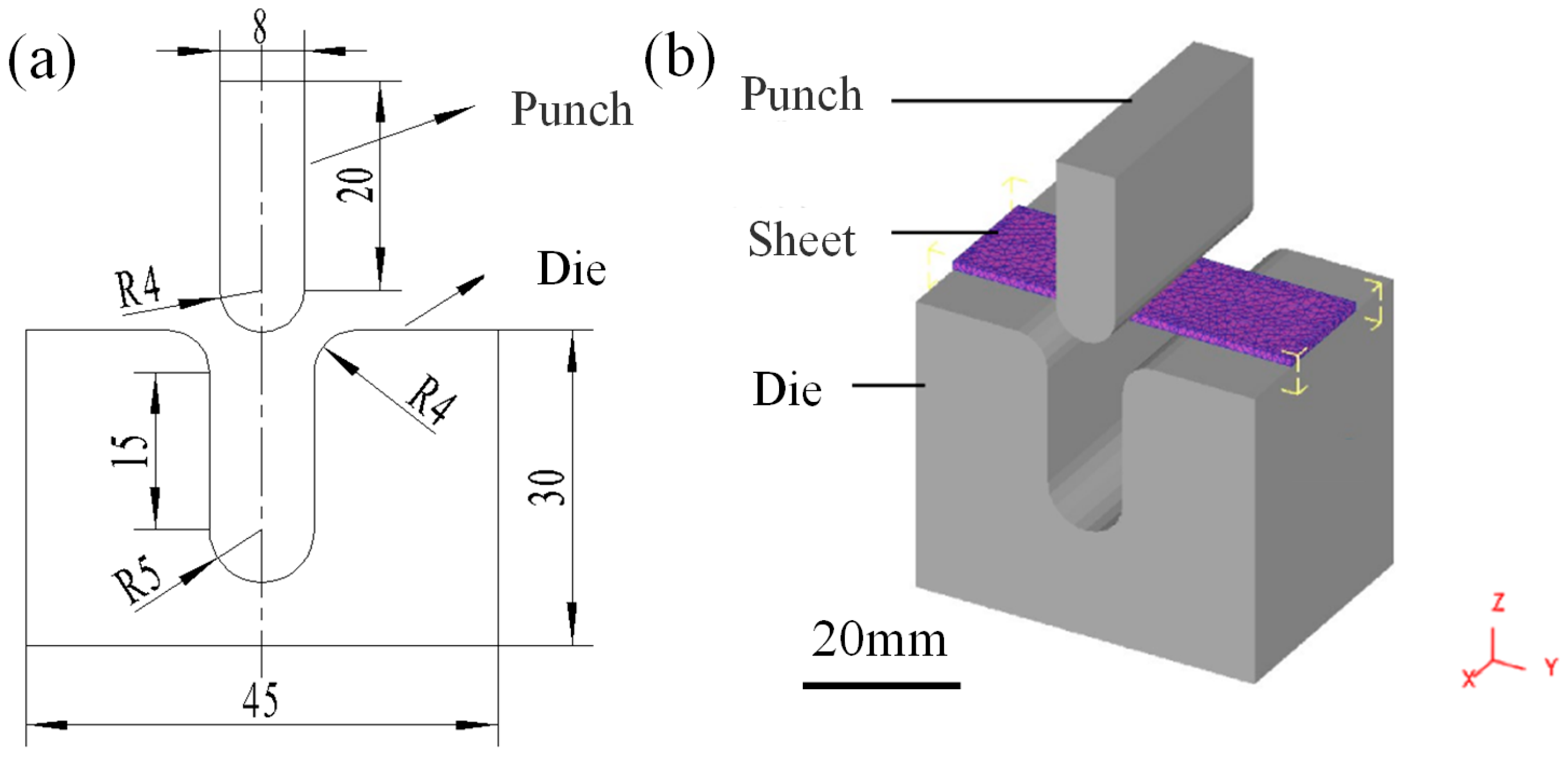
2.2. Establishment of Finite Element Model

Figure 3 shows the finite element geometric model of the sheet U-shaped bending. The dimensions of the magnesium alloy sheet were 45 mm × 15 mm × 1 mm. The size of the cavity die was 45 mm × 30 mm × 30 mm, the radius of the die fillet was 5 mm, the length of the die straight wall was 15 mm, and the transition zone between the flange and the straight wall was 4 mm. The sheet can be freely divided into 12,000 tetrahedral meshes, and the minimum edge length of a mesh is 0.5813 mm. The mold was set as a rigid body. The friction coefficient between the sheet and the die was set to 0.3.
During the deformation process, the mold and the sheet were in an isothermal state and did not exchange heat with the outside environment. The material parameters of the high-strength Mg-Gd-Y-Zn-Zr alloy can be input based on the constitutive model constructed by the above tensile test, as shown in Equation (2).
The loading method adopted was displacement loading. Boundary constraints were imposed on the punch, and it was allowed to move only along the negative Z axis; the displacement of the punch was 23 mm. In order to avoid the rigid body displacement of the sheet, a constraint was imposed on the centerline of the upper surface of the sheet: it could move only along the negative Z axis. The die was set to be fully fixed.

2.3. Analysis of Finite Element Results

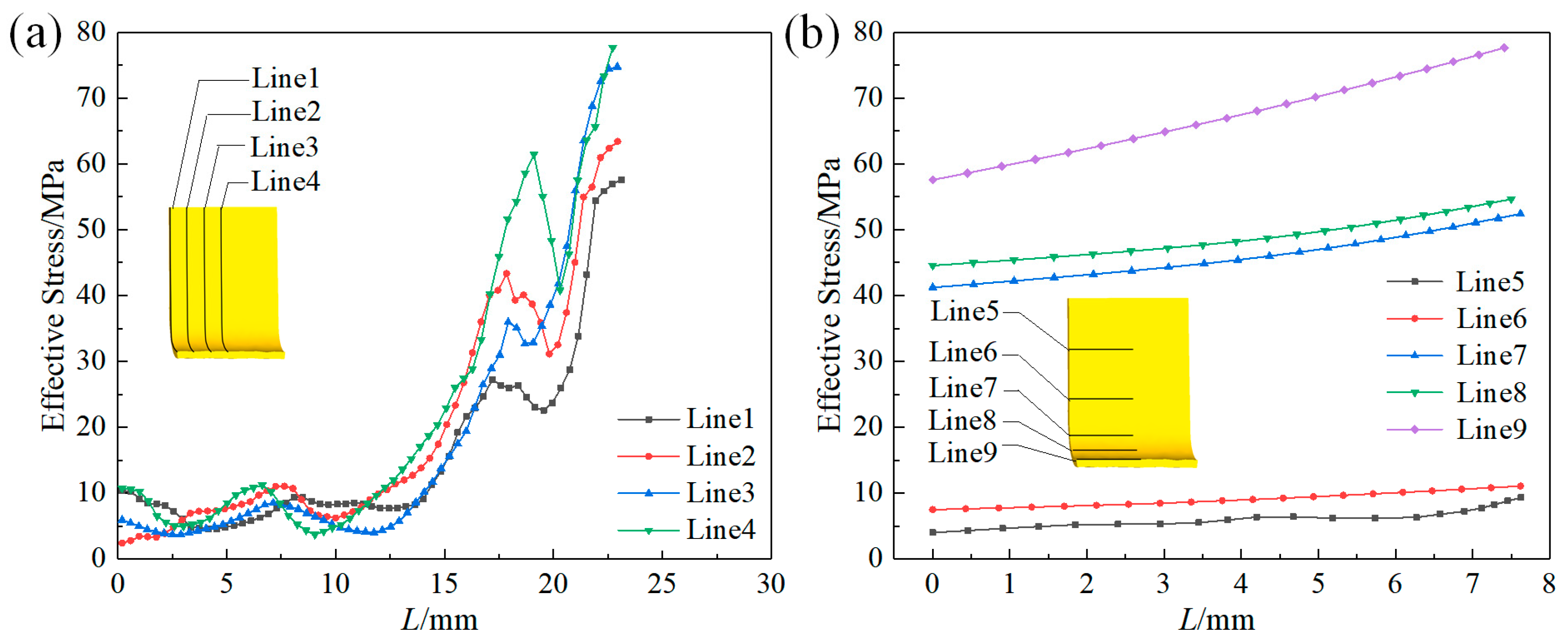
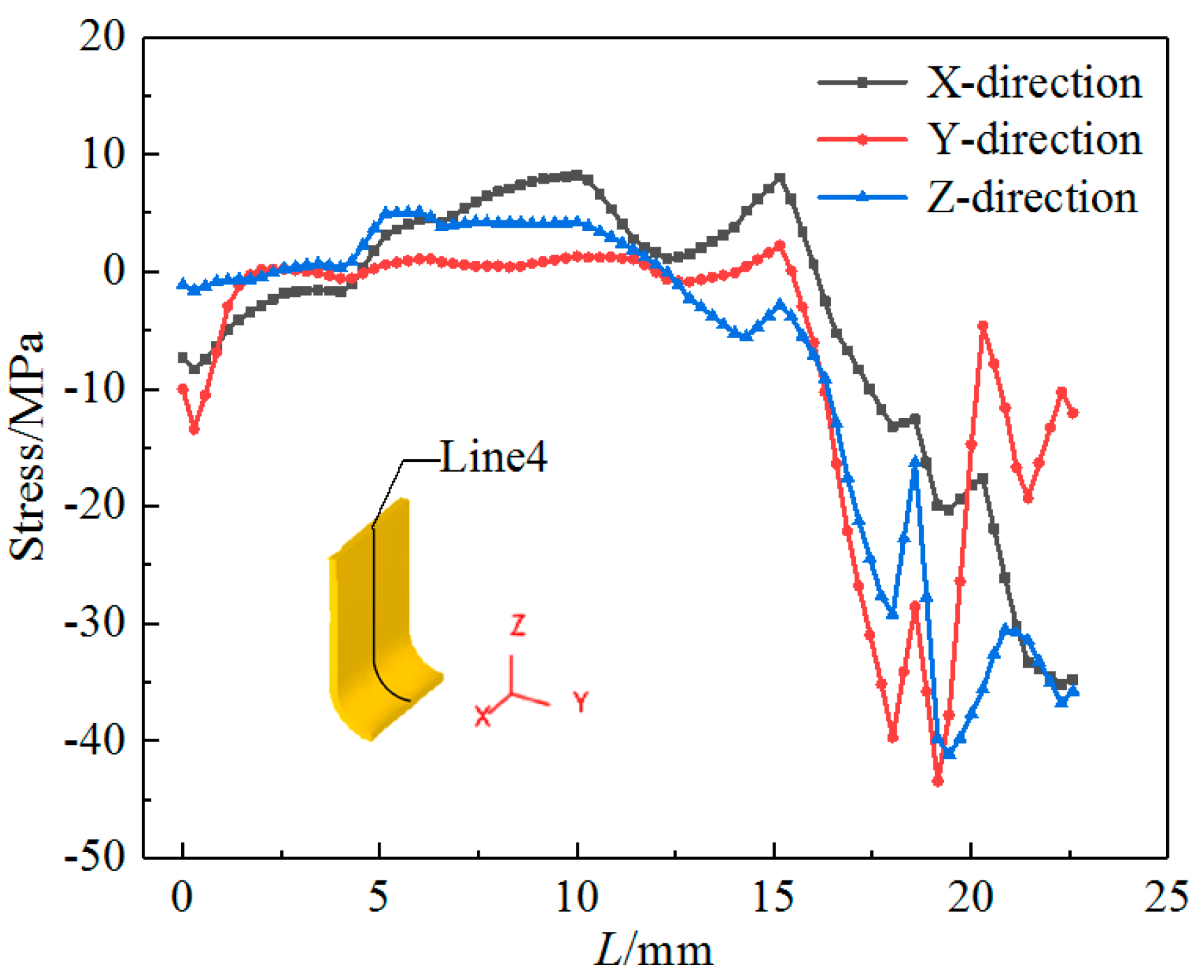
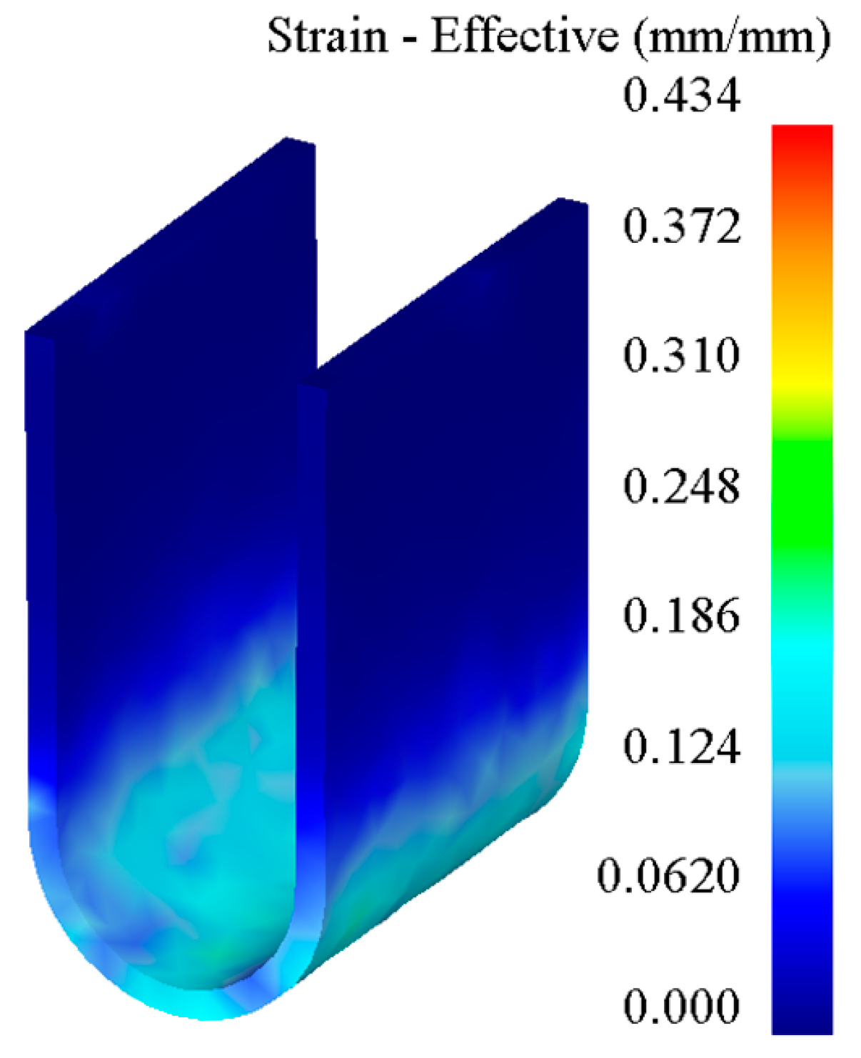
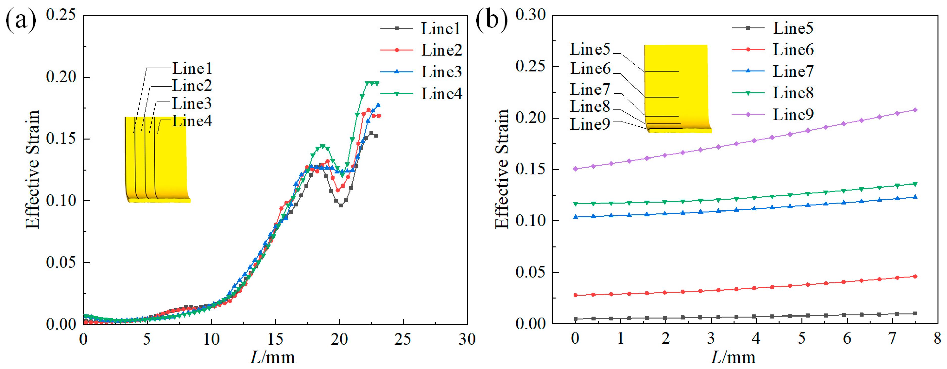
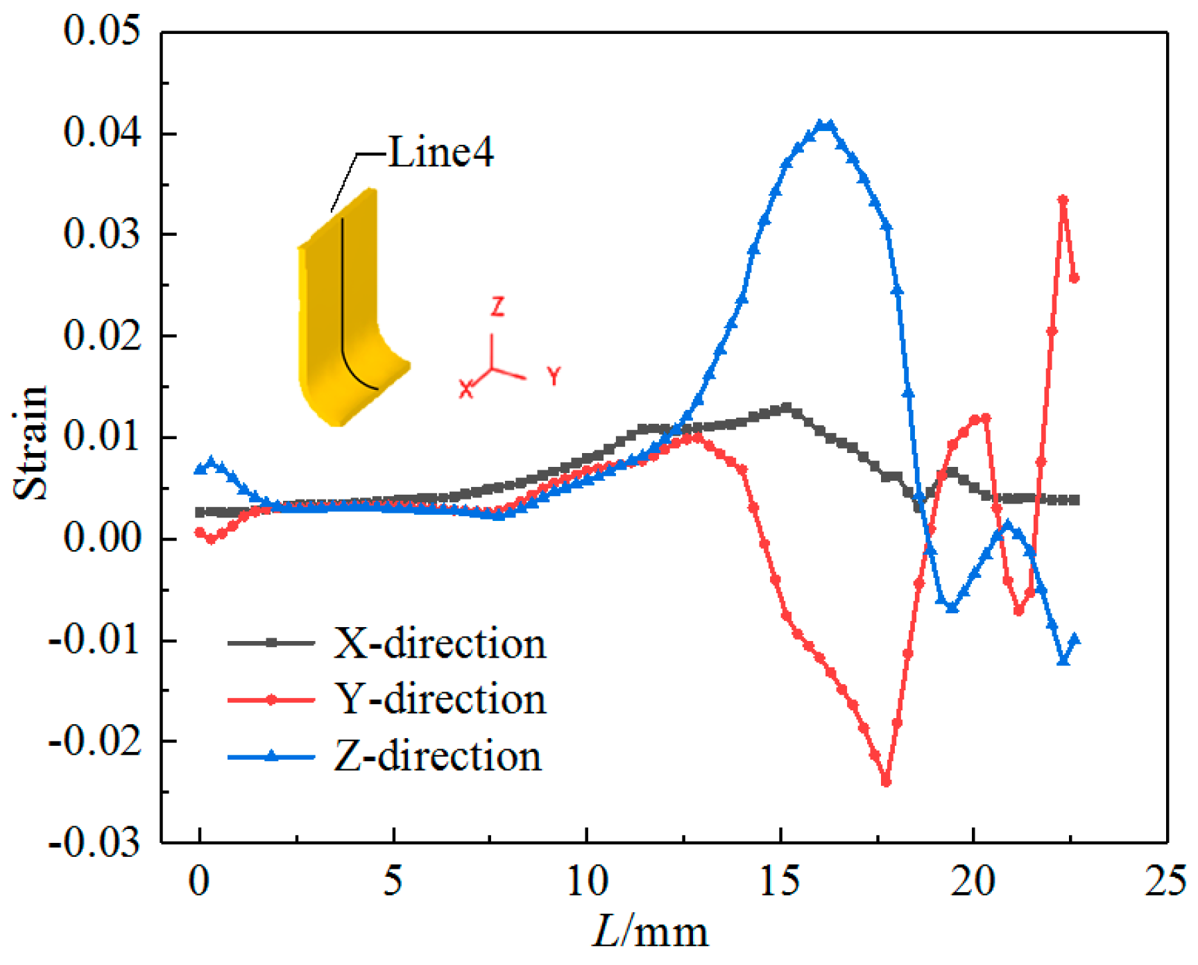
2.3.1. Stress–Strain Analysis

Considering the bending part at a forming temperature of 300 °C and a stamping speed of 20 mm/min as an example, the equivalent stress, equivalent strain, and free bending force of the bending part were analyzed.
Figure 4 shows the equivalent stress cloud diagram of the formed part. The equivalent stress of the straight wall area of the formed part is apparently very small, and the equivalent stress of the bottom end of the curved fillet is the largest, with a maximum value of 108 MPa. Figure 5 depicts the equivalent stress distribution curve of the formed part in different directions. Abscissa ‘L’ in the figures is the length of the vertical/horizontal distance from the edge of the straight wall area of the U-shaped part. In the vertical direction of Figure 5a, it is apparent that the equivalent stress value of the straight wall area is 5–12 MPa, and no plastic deformation occurs. From the straight wall area to the curved fillet area, the equivalent stress value gradually increases. The value reaches a distinct peak in the middle region of the curved fillet and then decreases, and the equivalent stress rapidly increases to a maximum in the bottom region of the curved fillet. In the horizontal direction of Figure 5b, the equivalent stress gradually increases from the edge to the core of the formed part. Among them, the increase in equivalent stress in the straight wall area is small, about 11 MPa, while the equivalent stress at the bottom of the bending fillet increases greatly; it is about 20 MPa.
Figure 6 shows a three-direction stress distribution curve diagram of the sheet material for the vertical direction. Clearly, in the later stage of the U-shaped bending of the sheet metal, the punch fillet and the middle area of the die bending fillet first extruded the sheet, resulting in an increase in the compressive stress in the Y and Z directions in this area. In the central region of the bending fillet, a distinct peak in the stress is apparent. In the bottom area of the curved fillet, the compressive stress in the X and Z directions increases, and the Y direction shows tensile stress during the extrusion action of the middle area of the curved fillet.
Figure 7 shows the equivalent strain cloud diagram of the formed part. Evidently, the equivalent strain of the straight wall area of the forming part is very small, and the equivalent strain of the bottom end of the curved fillet is the largest, with a maximum value of 0.434. This is because, during the forming process, the maximum amount of metal deformation occurred in the deformation zone of the curved fillet.
Figure 8 shows the equivalent strain distribution curve of formed parts for different directions. It can be seen from the vertical direction of Figure 8a that the equivalent strain value of the straight wall region is between 0.01 and 0.07. From the straight wall area to the curved fillet area, the equivalent strain value increases. The variation trend of the equivalent strain in the curved fillet area is basically the same as that of the equivalent stress. There is an apparent peak in the middle area of the curved fillet. The equivalent strain at the bottom end of the curved fillet is the largest. From the horizontal direction of Figure 8b, it is apparent that the equivalent strain increases gradually from the edge to the core of the formed part. Among them, the increase in equivalent strain in the straight wall area is very small, about 0.02, and the increase at the bottom of the curved fillet is the largest, about 0.06.
Figure 9 shows the three-direction strain distribution curve of the sheet material in the vertical direction. Clearly, in the later stage of the U-shaped bending of the sheet material, under the extrusion effect of the punch fillet and the middle area of the die bending fillet, the sheet produces a large compressive strain in the Y direction and a large tensile strain in the Z direction in this area, which leads to the generation of peaks. At the bottom end of the bending part, the deformation of the sheet material in the Y direction is severe, resulting in a large tensile strain. Owing to the large tensile strain, the largest equivalent strain occurs in this region.

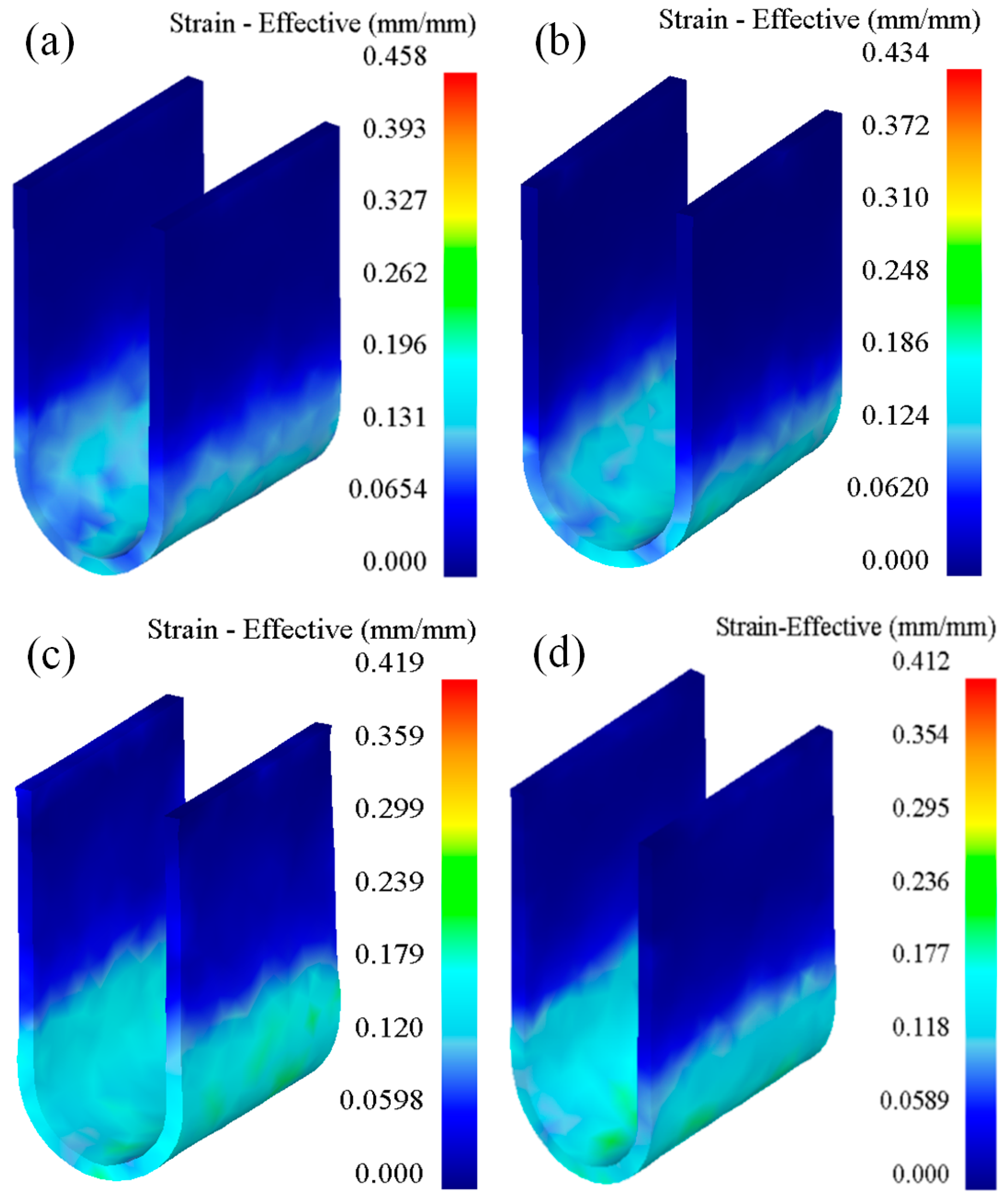
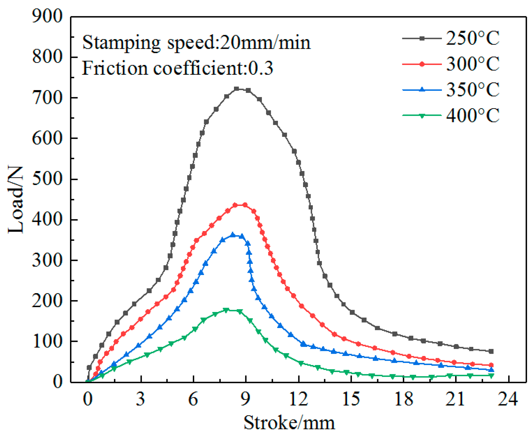
2.3.2. Effect of Temperature on Forming

The forming temperature strongly influences the plastic deformation ability of magnesium alloys. Studies have shown that when the forming temperature is above 250 °C, the plastic deformation ability can meet the forming requirements. If the forming temperature is greater than 400 °C, the magnesium alloy is easily oxidized and overburned, which severely affects the surface quality and mechanical properties of the formed parts. Under the premise of ensuring the excellent performance of the formed parts, the simulation temperature for the U-shape bending forming of high-strength Mg-Gd-Y-Zn-Zr alloy was set between 250 °C and 400 °C. In order to study the effect of the forming temperature on the formability of magnesium alloys, we considered four temperatures—250, 300, 350, and 400 °C—for finite element simulation, and the punching speed was set to 20 mm/min.
Figure 10 depicts the equivalent stress cloud diagrams of the formed parts for different temperatures. Clearly, with an increase in the forming temperature, the maximum value of the equivalent stress decreases; the maximum values are 268, 108, 94.7, and 28.9 MPa for 250, 300, 350, and 400 °C, respectively. This is mainly because the plastic deformation ability of magnesium alloys increases with the deformation temperature. When the temperature is close to 400 °C, the strain hardening phenomenon of the material is basically nonexistent, and hence the deformation resistance is very small.
Figure 11 shows the equivalent strain cloud diagrams of the formed parts for different temperatures. Apparently, with an increase in the forming temperature, the maximum value of the equivalent strain decreases; the maximum values are 0.458, 0.434, 0.419, and 0.412 for 250, 300, 350, and 400 °C, respectively. This is mainly because of the enhancement of the plastic deformation ability of the Mg-Gd-Y-Zn-Zr alloy sheet during the forming process, and the increase in the fluidity and deformation uniformity of the material, which result in a decrease in the maximum equivalent strain with an increase in the forming temperature.
Figure 12 shows the relationship between free bending force and stroke for different temperatures. Apparently, the variation of the curves for different temperatures is roughly similar: the free bending force first increases, then decreases, and finally tends to a constant value. With an increase in the forming temperature, the maximum value of the free bending force decreases; the maximum values are 722.49, 436.59, 362.22, and 178.15 N for 250, 300, 350, and 400 °C, respectively. Thus, as the forming temperature increases, the deformation resistance of the material decreases during bending.

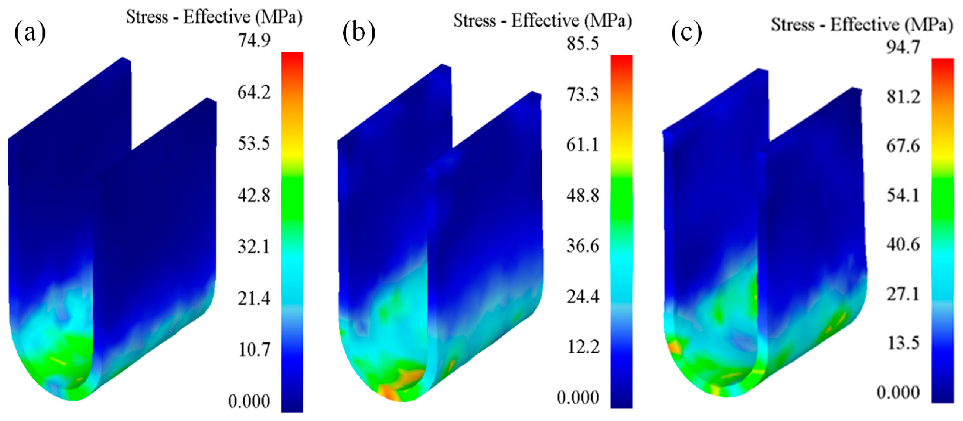
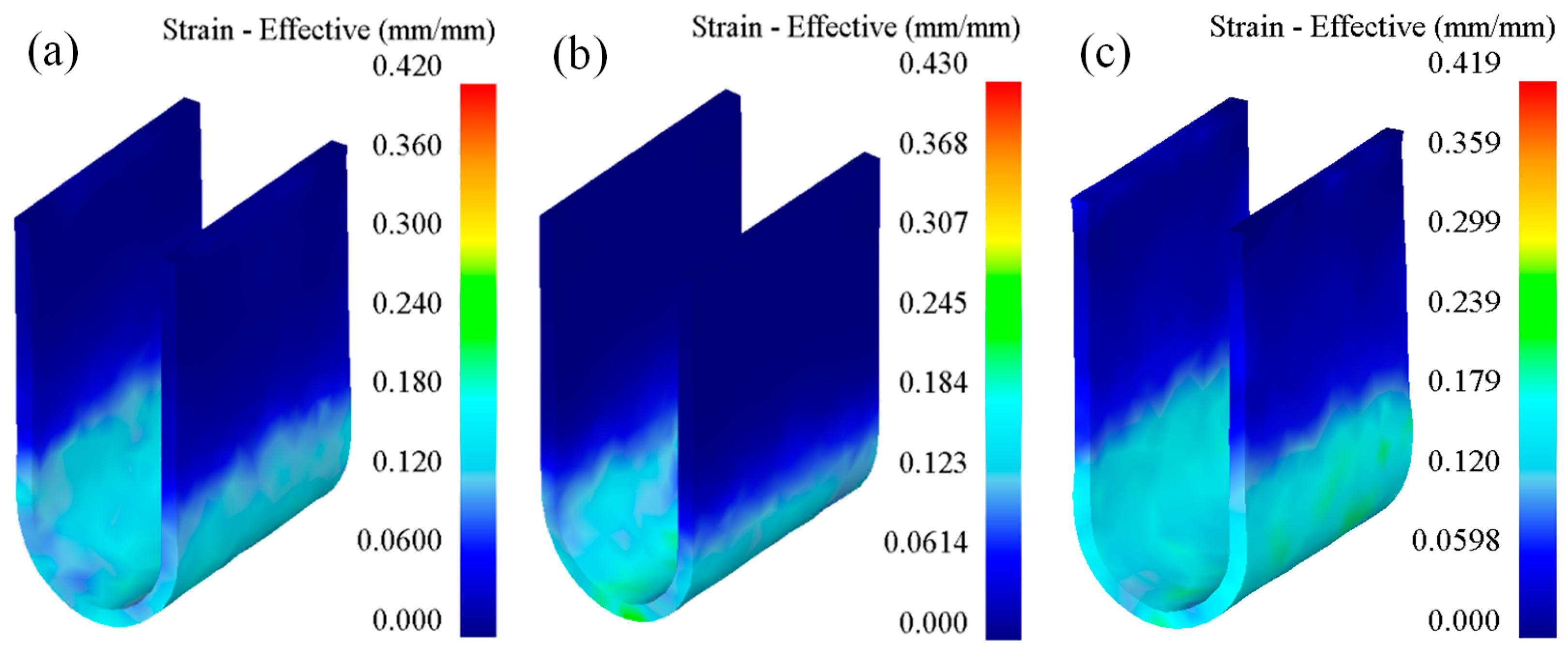
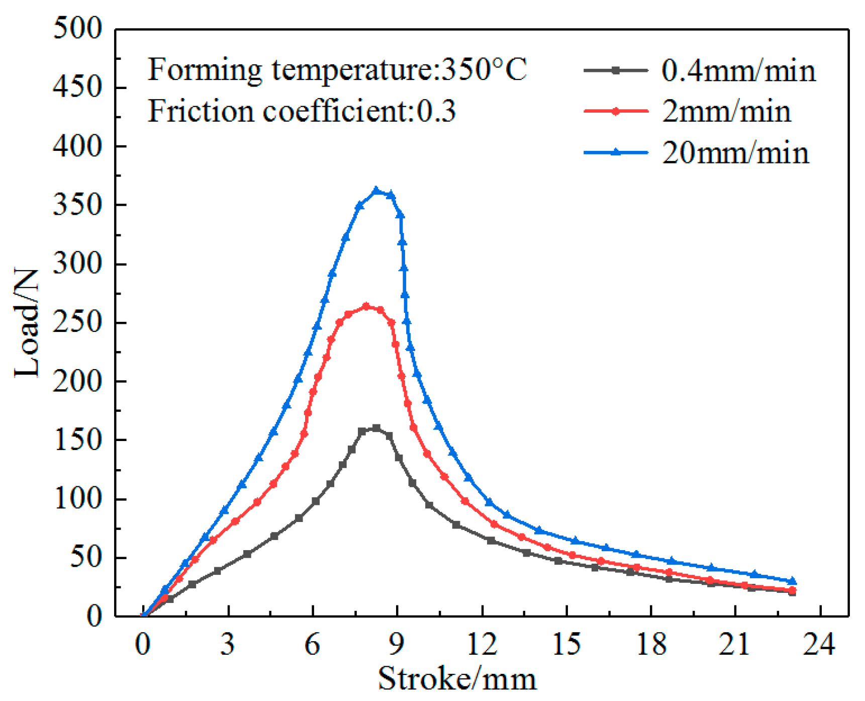
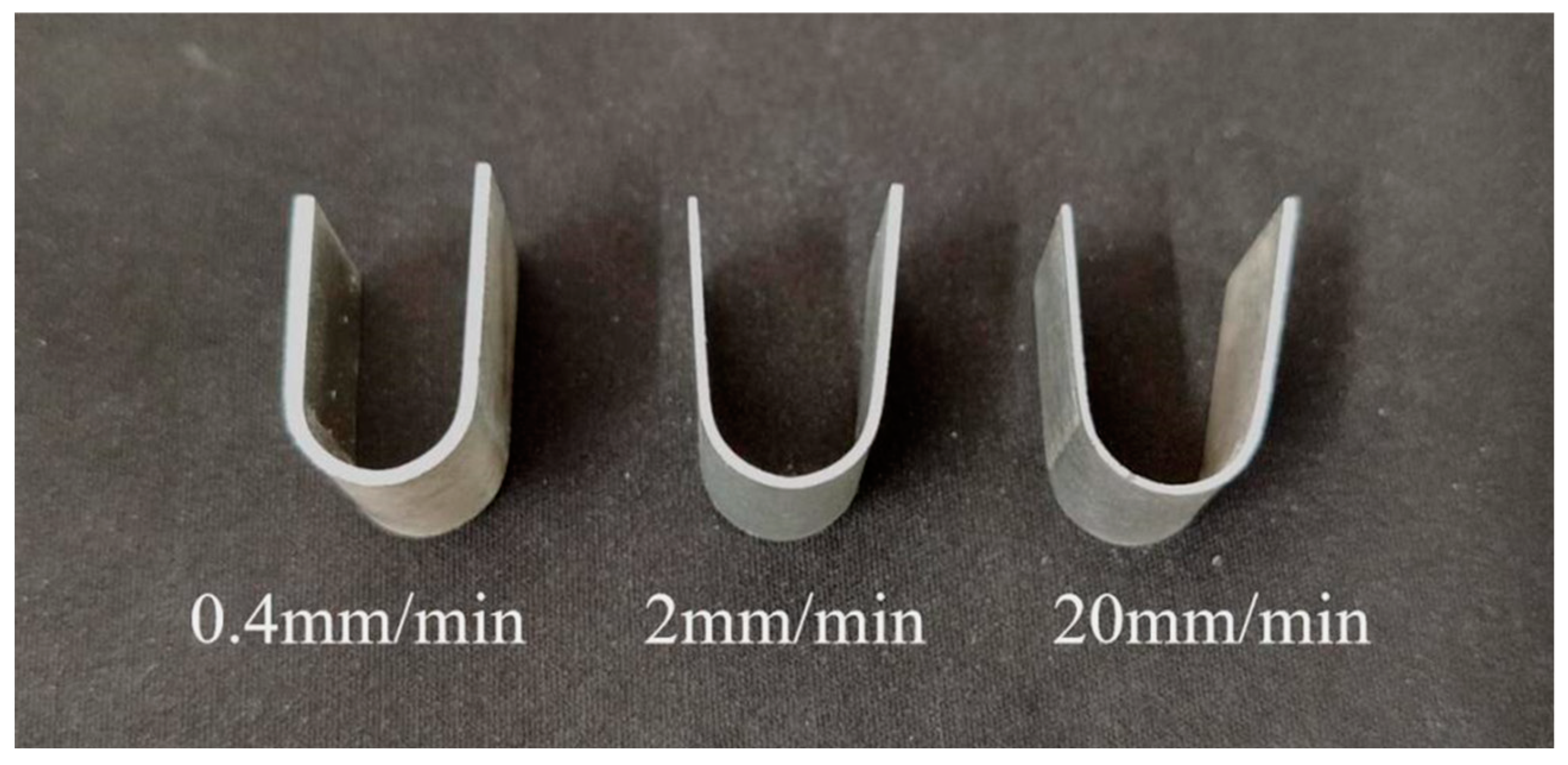
2.3.3. Effect of Stamping Speed on Forming

The deformation speed of the sheet during the stamping process is reflected macroscopically, as the speed of the punch is pressing down, namely the stamping speed. Under the premise of the same reduction, the higher the stamping speed, the shorter the time required for U-shaped bending, and hence the production efficiency is higher. However, the higher the stamping speed, the shorter the time available for the Mg-Gd-Y-Zn-Zr alloy sheet to recover, recrystallize, and soften; the degree of work hardening increases, and the formed parts are prone to fractures and other defects. Therefore, the forming temperature was set to 350 °C, and three different stamping speeds, namely 0.4, 2, and 20 mm/min, were chosen for the finite element simulation performed to study the effect of the stamping speed on the formability of magnesium alloys.
Figure 13 shows the equivalent stress cloud diagram of the formed parts for different stamping speeds. With an increase in the stamping speed, the maximum value of the equivalent stress increases; the maximum values are 74.9, 85.5, and 94.7 MPa for 0.4, 2, and 20 mm/min, respectively. With an increase in the stamping speed, the high-strength Mg-Gd-Y-Zn-Zr alloy sheet does not have sufficient time to recover, recrystallize, and soften. Consequently, the degree of work hardening increases and the ability of the material to resist plastic deformation increases, resulting in an increase in the maximum equivalent stress.
Figure 14 shows the equivalent strain cloud diagram of the formed parts for different stamping speeds. For the stamping speeds of 0.4, 2, and 20 mm/min, the maximum equivalent strains are 0.42, 0.43, and 0.419, respectively, and the maximum equivalent strain does not change significantly, which shows that the stamping speed has little effect on the equivalent strain of the bent part.
Figure 15 shows the relationship between the free bending force and the stroke of the formed part for different stamping speeds. Evidently, the variation of the free bending force is identical for the different stamping speeds. With an increase in the stamping speed, the free bending force increases. The values of the force are 160.73, 264.01, and 362.22 N for stamping speeds of 0.4, 2, and 20 mm/min, respectively, which shows that under the conditions suitable for ensuring the quality of the formed parts, choosing the appropriate stamping speed can reduce the tonnage of the pressure equipment.

3. U-Bending Test

The test sheet was an Mg-Gd-Y-Zn-Zr alloy sheet with a thickness of 1 mm, a width of 15 mm, and a length of 45 mm. The warm U-bending test parameters are presented in Table 1, and the bending forming die designed according to the sheet size is shown in Figure 16. The bending and forming equipment was the Inspekt Table-100 kN electronic universal material testing machine. The main parameters of the equipment were as follows: the maximum test force was 100 kN, the beam speed was 0.01–400 mm/min, the return speed was 400 mm/min, and the stroke measurement resolution was less than 1 μm.
Figure 17 shows the U-shaped parts formed at a stamping speed of 20 mm/min and different temperatures, and Figure 18 shows the U-shaped parts formed at a forming temperature of 350 °C and different stamping speeds.
The U-shaped bending of the sheet was roughly the combination of two V-shaped bendings. The bending stroke h has the following relationship with the bending angle α:
When h < rp + rd + t, the relationship between the free bending force and the stroke is shown in Formula (3).
P = μ s i n α + c o s α b t 2 σ S 2 μ t + h + r p + r d 1 c o s α t / s i n α .
When h > rp + rd + t, the relationship between the free bending force and the stroke is shown in Formula (4).
P = μ s i n α + c o s α b t 2 σ S 2 μ t + h r p + r d + t 1 c o s α / c o s α ,
where, μ is the friction coefficient, α is the bending angle, P is the free bending force, rp is the punch fillet radius, rd is the die fillet radius, h is the bending stroke, t is the thickness of the sheet, and σS is the yield strength of the sheet.
Figure 19 shows the relationship between the free bending force and the stroke. Apparently, when the punch lowers, the free bending force gradually increases first, then gradually decreases after reaching a peak value, and then tends to be constant. When the sheet lowers to 9 mm, the free bending force test value reaches 404 N, the theoretical value of the free bending force becomes 416 N, the simulated value of the free bending force becomes 430 N, and the error becomes less than 10%. That is, the simulated value of the free bending force > the theoretical value of the free bending force > the experimental value. At 13 mm, the error between the experimental value and the simulated value is the largest, namely 122 N, but the change trends of the experimental value, theoretical value, and simulation value are consistent, which indicates that the established material constitutive model can accurately characterize the U-bending of high-strength Mg-Gd-Y-Zn-Zr alloys.

4. Conclusions

(1)
In this study, a constitutive model for the Mg-Gd-Y-Zn-Zr alloy sheet was established on the basis of tensile tests, and the U-shape bending forming of the sheet under different process conditions was simulated using the finite element software DEFORM. Variation rules of the equivalent stress, equivalent strain, and free bending force of the formed parts were obtained at different temperatures and stamping speeds.
(2)
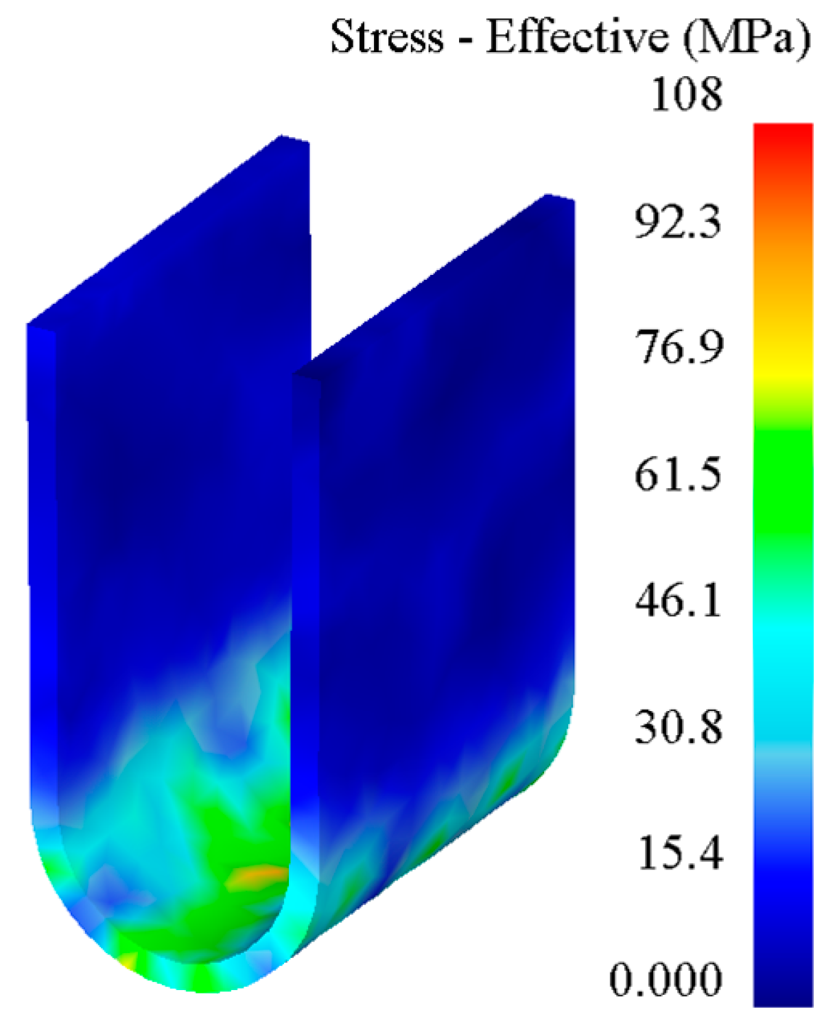
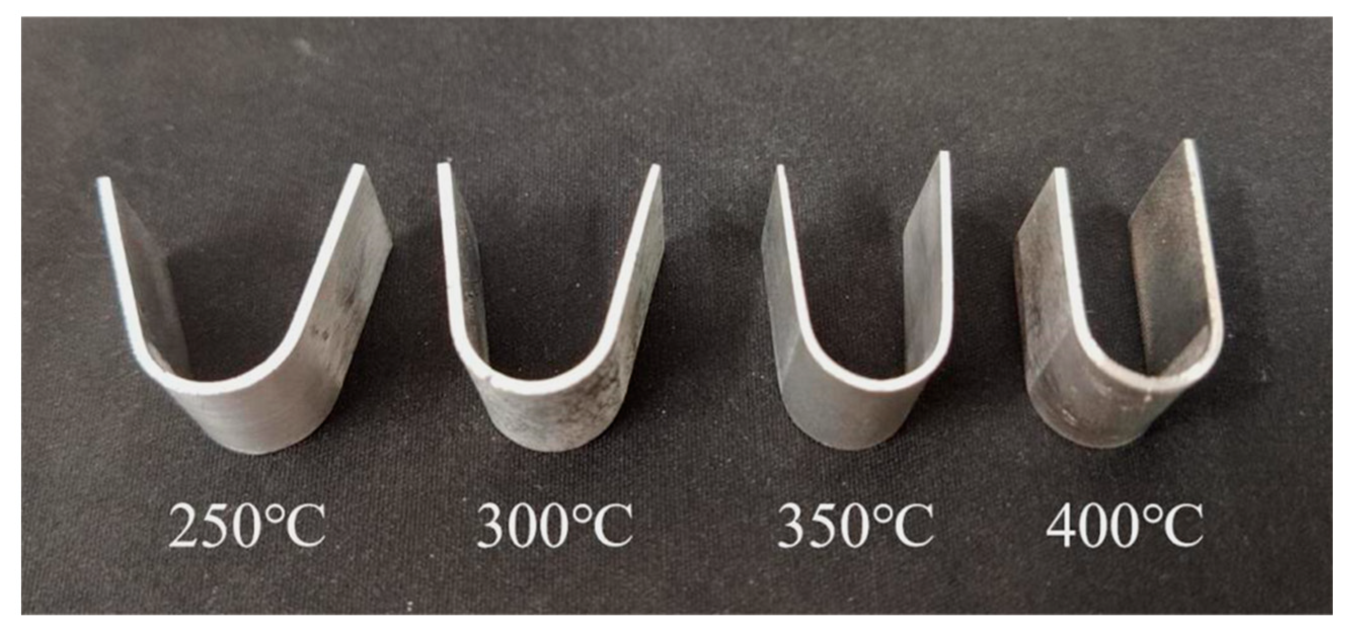
In the bending forming of U-shaped parts, from the straight wall area to the curved corner area and from the edge to the core, the equivalent stress and equivalent strain of the formed part gradually increased. As the forming temperature increased, the equivalent stress, equivalent strain, and free bending force of the formed part decreased. With an increase in the stamping speed, the equivalent stress and free bending force of the formed parts increased, but the equivalent strain did not change significantly.
(3)
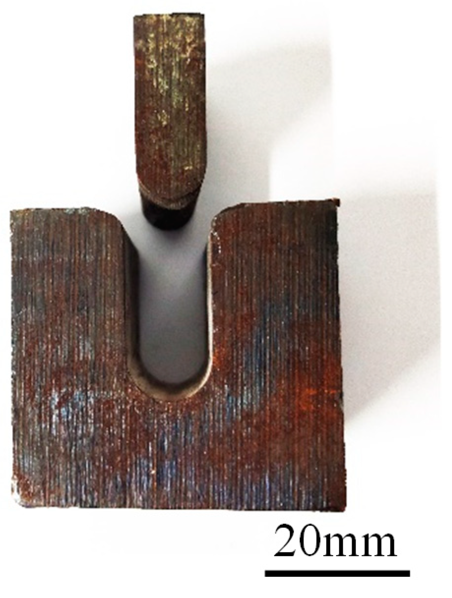
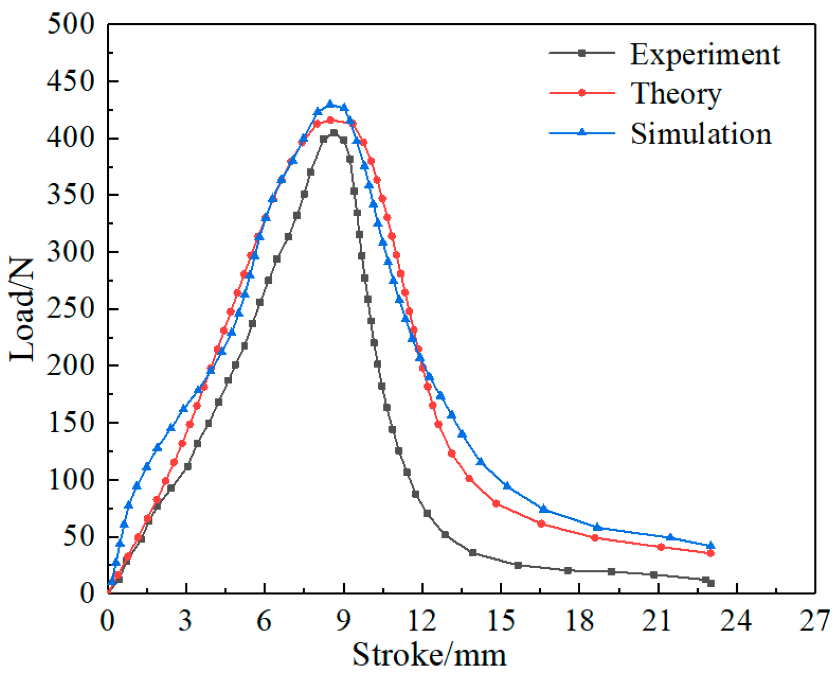
The error in the maximum free bending force between the test and simulation results was less than 10%. The established material constitutive model can accurately characterize the U-shape bending forming of high-strength Mg-Gd-Y-Zn-Zr alloys. The present research results can provide guidance for the stamping forming of high-strength Mg-Gd-Y-Zn-Zr alloy sheets. However, the influence mechanism between the forming process of U-shaped parts and the microstructure and mechanical properties of materials needs to be further studied.

Author Contributions

All authors contributed to the study conception and design. Material preparation, data collection and analysis were performed by H.W., A.H., S.X. and C.Z. The first draft of the manuscript was written by H.W. and J.L. All authors commented on previous versions of the manuscript. All authors have read and agreed to the published version of the manuscript.

Funding

This research received no external funding.

Data Availability Statement

Not applicable.

Conflicts of Interest

The authors declare no conflict of interest.

References

  1. Wu, G.H.; Wang, C.L.; Sun, M.; Ding, W.J. Recent developments and applications on high-performance cast magnesium rare-earth alloys. J. Magnes. Alloys 2021, 9, 1–20. [Google Scholar] [CrossRef]
  2. Song, J.F.; Chen, J.; Xiong, X.M.; Peng, X.D.; Chen, D.L.; Pan, F.S. Research advances of magnesium and magnesium alloys worldwide in 2021. J. Magnes. Alloys 2022, 10, 863–898. [Google Scholar] [CrossRef]
  3. Tong, C.P.; Rong, Q.; Yardley, V.A.; Li, X.T.; Luo, J.M.; Zhu, G.S.; Shi, Z.S. New developments and future trends in low-temperature hot stamping technologies: A Review. Metals 2020, 10, 1652. [Google Scholar] [CrossRef]
  4. Zhang, R.Q.; Shi, Z.S.; Yardley, V.A.; Lin, J.G. Experimental studies of necking and fracture limits of boron steel sheet under hot stamping conditions. J. Mater. Process. Technol. 2022, 302, 117481. [Google Scholar] [CrossRef]
  5. Atxaga, G.; Arroyo, A.; Canflanca, B. Hot stamping of aerospace aluminium alloys: Automotive technologies for the aeronautics industry. J. Manuf. Process. 2022, 81, 817–827. [Google Scholar] [CrossRef]
  6. Zhao, P.J.; Wu, Q.; Yang, Y.L.; Chen, Z.H. Process Optimization of the Hot Stamping of AZ31 Magnesium Alloy Sheets Based on Response Surface Methodology. Materials 2023, 16, 1867. [Google Scholar] [CrossRef] [PubMed]
  7. Wang, H.T.; Ma, L.F.; Jia, W.T.; Xie, H.B.; Lu, L.W. Analysis of room-temperature stamping formability of complex features of AZ31 magnesium alloy variable-curvature plate shell. Int. J. Adv. Manuf. Technol. 2022, 123, 3159–3169. [Google Scholar] [CrossRef]
  8. Luo, A.A.; Shi, R.H.; Miao, J.S.; Avey, T. Review: Magnesium Sheet Alloy Development for Room Temperature Forming. JOM 2021, 73, 1403–1418. [Google Scholar] [CrossRef]
  9. Zhang, L.; Huang, G.S.; Zhang, H.; Song, B. Cold stamping formability of AZ31B magnesium alloy sheet undergoing repeated unidirectional bending process. J. Mater. Process. Technol. 2011, 211, 644–649. [Google Scholar] [CrossRef]
  10. Han, T.Z.; Huang, G.S.; Wang, Y.G.; Wang, G.G.; Zhao, Y.C.; Pan, F.S. Enhanced mechanical properties of AZ31 magnesium alloy sheets by continuous bending process after V-bending. Prog. Nat. Sci. 2016, 26, 97–102. [Google Scholar] [CrossRef]
  11. Wang, W.R.; Huang, L.; Tao, K.H.; Chen, S.C.; Wei, X.C. Formability and numerical simulation of AZ31B magnesium alloy sheet in warm stamping process. Mater. Des. 2015, 87, 835–844. [Google Scholar] [CrossRef]
  12. Chen, F.K.; Huang, T.B. Formability of stamping magnesium-alloy AZ31 sheets. J. Mater. Process. Technol. 2003, 142, 643–647. [Google Scholar] [CrossRef]
  13. Berge, F.; Winderlich, H.; Krbetschek, C.; Ullmann, M.; Kawalla, R. The effect of sheet thickness, loading rate and punch diameter on the deformation behaviour of AZ31 during 3-point bending. Mater. Sci. Forum 2016, 854, 65–72. [Google Scholar] [CrossRef]
  14. Wei, Y.H.; Lu, L.W.; Li, M.H.; Ma, M.; Huang, W.Y.; Zhao, X.; Wu, R.Z. Effect of 90° route on microstructure of AZ31 magnesium alloy sheets by forging-bending repeated deformation. J. Alloys Compd. 2023, 948, 169720. [Google Scholar] [CrossRef]
  15. Chen, Y.F.; Zhu, Z.Q.; Zhou, J.X. Study on the strengthening mechanism of rare earth yttrium on magnesium alloys. Mater. Sci. Eng. A 2022, 850, 143513. [Google Scholar] [CrossRef]
  16. Deng, J.F.; Tian, J.; Zhou, Y.C.; Chang, Y.Y.; Liang, W.; Ma, J.Y. Plastic deformation mechanism and hardening mechanism of rolled Rare-Earth magnesium alloy thin sheet. Mater. Des. 2022, 218, 110678. [Google Scholar] [CrossRef]
  17. Calado, L.M.; Carmezim, M.J.; Montermor, M.F. Rare Earth Based Magnesium Alloys -A Review on WE Series. Front. Mater. 2022, 9, 804906. [Google Scholar] [CrossRef]
  18. Wang, Y.J.; Jiang, H.T.; Liu, C.M.; Zhang, Y.; Guo, W.Q.; Kang, Q.; Xu, Z.; Wang, P.P. Effect of Ca-addition on hot deformation behavior and workability of Mg-Gd-Y-Zn-Zr alloy. Rare Metal Mat. Eng. 2020, 49, 1650–1656. [Google Scholar]
  19. Liu, H.L.; Meng, Y.Z.; Yu, H.S.; Xu, W.L.; Zhang, S.Y.; Jia, L.C.; Wu, G.Q. The role of long period stacking ordered phase in dynamic recrystallization of a Mg-Gd-Y-Zn-Zr Alloy during multi-directional forging process. Materials 2020, 13, 3290. [Google Scholar] [CrossRef]
  20. Zhou, X.J.; Liu, C.M.; Gao, Y.H.; Jiang, S.N.; Chen, Z.Y. Improved workability and ductility of the Mg-Gd-Y-Zn-Zr alloy via enhanced kinking and dynamic recrystallization. J. Alloys Compd. 2018, 749, 878–886. [Google Scholar] [CrossRef]
  21. Li, B.; Teng, B.G.; Chen, G.X. Microstructure evolution and mechanical properties of Mg-Gd-Y-Zn-Zr alloy during equal channel angular pressing. Mater. Sci. Eng. A 2019, 744, 396–405. [Google Scholar] [CrossRef]
  22. Ramezani, S.M.; Zarei-Hanzaki, A.; Anoushe, A.S.; Abedi, H.R.; Minarik, P.; Máthis, K.; Horváth, F.K. A new insight into LPSO transformation during multi-axial forging in Mg-Gd-Y-Zn-Zr alloy. Mater. Lett. 2020, 269, 127625. [Google Scholar] [CrossRef]
Figure 1. The true stress–strain curves of high-strength Mg-Gd-Y-Zn-Zr alloy under different tensile deformation conditions: (a) 6.06 × 10⁻⁴ s−1; (b) 3.03 × 10⁻³ s−1; (c) 6.06 × 10⁻³ s−1; (d) 1.52 × 10⁻² s−1.
Metals 13 01477 g001
Figure 2. Linear regression curves of the constitutive-equation-related parameters: (a ln σ p ln ε ˙ ; (b σ p ln ε ˙ ; (c ln sinh α σ ln ε ˙ ; (d 1000 / T ln [ sinh ( α σ ) ] .
Metals 13 01477 g002
Figure 3. Finite element model of the sheet U-shaped bending: (a) 2D schematic, (b) 3D model.
Metals 13 01477 g003
Figure 4. Equivalent stress cloud diagram of the formed part.
Metals 13 01477 g004
Figure 5. Equivalent stress distribution curve of the formed part in different directions; (a) vertical direction, (b) horizontal direction.
Metals 13 01477 g005
Figure 6. Three-dimensional stress distribution curve of sheet metal for the vertical direction.
Metals 13 01477 g006
Figure 7. Equivalent strain cloud diagram of the formed part.
Metals 13 01477 g007
Figure 8. Equivalent strain distribution curve of formed parts for different directions; (a) vertical direction, (b) horizontal direction.
Metals 13 01477 g008
Figure 9. Three-dimensional strain distribution curve of sheet metal for the vertical direction.
Metals 13 01477 g009
Figure 10. Cloud chart of equivalent stress of formed parts for different temperatures; (a) 250 °C, (b) 300 °C, (c) 350 °C, and (d) 400 °C.
Metals 13 01477 g010
Figure 11. Cloud chart of equivalent strain of formed parts for different temperatures; (a) 250 °C, (b) 300 °C, (c) 350 °C, and (d) 400 °C.
Metals 13 01477 g011
Figure 12. Relationship curves between free bending force and stroke for different temperature conditions.
Metals 13 01477 g012
Figure 13. Equivalent stress cloud diagram of the formed parts for different stamping speeds; (a) 0.4 mm/min, (b) 2 mm/min, and (c) 20 mm/min.
Metals 13 01477 g013
Figure 14. Equivalent strain cloud diagram of the formed parts for different stamping speeds; (a) 0.4 mm/min, (b) 2 mm/min, and (c) 20 mm/min.
Metals 13 01477 g014
Figure 15. Relationship curve between free bending force and stroke for different stamping speeds.
Metals 13 01477 g015
Figure 16. Physical drawing of die.
Metals 13 01477 g016
Figure 17. U-shaped parts formed at different temperatures and at a stamping speed of 20 mm/min.
Metals 13 01477 g017
Figure 18. U-shaped parts formed at different stamping speeds and at a temperature of 350 °C.
Metals 13 01477 g018
Figure 19. Relation curve between the free bending force and the stroke.
Metals 13 01477 g019
Table 1. Warm U-bending test parameters for Mg-Gd-Y-Zn-Zr alloy.
Process ParametersForming Temperature/°C
250300350400
Stamping speed mm/min----0.4--
----2--
20202020
Disclaimer/Publisher’s Note: The statements, opinions and data contained in all publications are solely those of the individual author(s) and contributor(s) and not of MDPI and/or the editor(s). MDPI and/or the editor(s) disclaim responsibility for any injury to people or property resulting from any ideas, methods, instructions or products referred to in the content.

