Abstract
The failure of resistance spot welds through the fusion zone along the sheet/sheet interface (i.e., interfacial failure) is critical for automotive crashworthiness. This paper investigates the effect of fusion zone hardness on the interfacial failure behavior of resistance spot welds during the tensile–shear test. AISI 1040 medium carbon steel, producing a high level of hardness mismatch during resistance spot welding, was selected as the base metal. By ex situ tempering heat treatment, various levels of fusion zone hardness are achieved in the welds with constant fusion zone size. It is shown that the interfacial failure of the spot welds is a competition between ductile shear failure and rapid crack propagation. It is found that there is a critical fusion zone hardness beyond which the interfacial failure mechanism transitions from ductile shear failure to rapid crack propagation. In welds with high fusion zone hardness, the mechanism of interfacial failure is rapid crack growth, and fusion zone fracture toughness is the governing factor for the interfacial failure load. Conversely, in welds with low FZ hardness, the mechanism of interfacial failure is a ductile shear failure, and fusion zone hardness would be the governing factor for the interfacial failure load.
1. Introduction
Steel has long been the primary material of choice for automotive manufacturers due to its capability to meet the requirements of the automotive industry, such as performance flexibility, low cost, weight reduction, crash safety, fuel economy, durability, and recyclability. Typically, more than 50% of the total weight of a modern vehicle consists of steel. Most of this steel is found in the skeleton structure of the automobile, which is called body-in-white (BIW). A newer generation of automotive steel grades called advanced high strength steel (AHSS) with an excellent combination of strength and ductility has been introduced to reduce vehicle components’ weight by up to 25% without compromising crashworthiness [1,2,3,4,5].
BIW assembly is the process where various sheet metal components are welded together. Among different welding methods, resistance spot welding (RSW) is the primary joining method to assemble steel car body components due to its low cost, high-speed operation, and automation possibility. Generally, BIW in a modern vehicle contains thousands of spot welds [6,7]. However, the RSW of AHSS is accompanied by metallurgical challenges. The specialized multiphase microstructure of AHSS is destroyed due to RSW thermal cycle. Extremely rapid cooling rate induced by water-cooled copper electrodes leads to martensite formation in the fusion zone (FZ) of AHSS RSWs (except for 2nd generation AHSS) [8,9,10]. The brittleness of the hard martensite can result in an overmatched hardness in the FZ of spot welds affecting weld ductility and failure mode transition [7,8,11,12]. Although an overmatched nugget is beneficial from the failure mode point of view, an excessive hardness in FZ could result in brittle cleavage fracture [13,14]. Moreover, Zhang et al. [15] showed that the hardnessmismatch factor (i.e., hardness ratio of the fusion zone to the base metal) directly affects the degree of strength loss caused by LME cracks in RSW of Zn-coated AHSS. It was found that LME cracks have a far more detrimental impact on RSW strength under a low hardness ratio compared to when the hardness ratio is high.
Another challenging issue that was reported for AHSS RSWs is their high susceptibility to fail in interfacial mode (IF) while exposed to mode II loading conditions (e.g., tensile–shear loading) [14,16,17]. According to Pouranvari [18], there are two distinct mechanisms for the interfacial failure of AHSS spot welds during tensile–shear loading:
- (i)
- Ductile shear failure: interfacial failure occurs when the induced shear stress at the sheet/sheet interface exceeds the ultimate shear strength of the FZ (). Under such circumstances, the failure load in IF mode can be expressed as Equation (1):
- (ii)
- Rapid crack propagation: interfacial failure occurs when stress intensity factor KI at the notch tip reaches the critical stress intensity factor KC or fracture toughness of the FZ. Under such circumstances, Equation (3) can be applied to estimate the failure load in IF mode.
Therefore, interfacial failure strength in the ductile shear failure mechanism is governed by the FZ hardness, while interfacial failure in the second mechanism is dictated by the FZ fracture toughness [18].
In the previous study by Pouranvari [18], the ratio of the fracture toughness to the hardness of the FZ was introduced as the critical governing factor determining the interfacial failure mechanism. However, experimental determination of fracture toughness of RSW nuggets is impossible by traditional methods. Therefore, the FZ hardness value is the main criterion governing the interfacial failure mechanism in the current study. This study aims to determine in what range of hardness values the interfacial failure load is dictated by FZ hardness and in what range it is governed by FZ fracture toughness. For this purpose, examining interfacial failure behavior in a wide range of FZ hardness is necessary. AISI 1040 steel, containing a relatively high amount of carbon, can produce high hardness after martensitic transformation. By conducting ex situ tempering heat treatment after RSW, it is possible to achieve different hardness levels in the FZ. This characteristic enables us to study the effect of FZ hardness on interfacial failure behavior while the nugget size is constant.
2. Materials and Methods
2.1. Materials
A 2 mm thick uncoated AISI 1040 steel sheet was selected as the base metal for this study. The chemical composition and room-temperature mechanical properties of this steel were determined by quantometer analysis and tensile test (based on ASTM E8 standard), the results of which are given in Table 1. Figure 1a illustrates the engineering stress–strain curve of the as-received AISI 1040 steel showing discontinued yielding behavior. This grade of steel was selected due to its high hardenability leading to a high level of hardness mismatch after resistance spot welding. The relatively high carbon concentration in this steel (0.4%wt.) enabled us to produce a high level of hardness mismatch after RSW that can be reduced to various levels by ex situ tempering heat treatment, as will be discussed later. AISI 1040 steel exhibits a ferrite–pearlite microstructure, as illustrated in Figure 1b. This microstructure does not undergo any phase transformation while exposed to tempering heat treatment.

Table 1.
Chemical composition and mechanical properties of the investigated AISI 1040 steel.
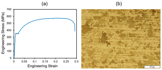
Figure 1.
(a) Engineering stress–strain curve, and (b) Light optical micrograph of the investigated AISI 1040 steel.
2.2. Resistance Spot Welding Procedure
The steel sheet was cut into 100 × 25 mm coupons along the transverse direction. Sheet specimens were overlapped by 25 mm, and a resistance spot was welded at the center of the overlapped region, as seen in Figure 2. RSW was performed using a PLC-controlled, 120 kVA AC pedestal-type RSW machine. 45-degree truncated-cone RMWA class two electrodes with an 8 mm face diameter were used for spot welding. Since this research aims to investigate the interfacial failure of spot welds, welding parameters must be optimized to produce a weld to fail in IF mode during the tensile–shear test and simultaneously be larger than the 4t0.5 weld sizing criterion. The best welding schedule that can produce such a weld with a nugget diameter of 6.5 mm is given in Table 2. These parameters were kept constant for all specimens to produce the same weld nugget sizes.
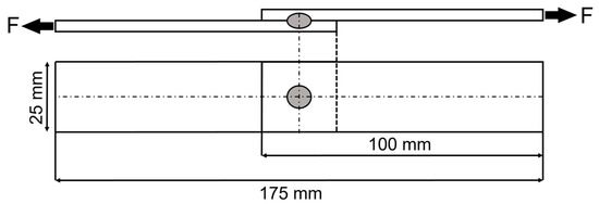
Figure 2.
Schematic of specimen dimensions for tensile–shear test.
Table 2.
Welding parameters applied in RSW process.
2.3. Ex Situ Tempering Heat Treatment
After welding, the tensile–shear and metallographic specimens were subjected to tempering heat treatment in a salt bath furnace. They were tempered within the 250–650 °C temperature range with a dwell time of 15 min by being immersed in a molten salt bath. It is well known that heat treatment in salt bath furnaces can lead to more accurate and reproducible results due to the fact that the heat transfer rate in molten salt is much greater than in other heating mechanisms, such as radiation or convection through the gas. Owing to the wide tempering temperature range in this study, three combinations of salt types with different operating temperatures were chosen following their melting and decomposition points, as shown in Table 3. Note that the listed mole fractions for KNO3-NaNO3 and NaCl-CaCl2 refer to their eutectic compositions according to the phase diagrams of the corresponding salts. Temperature checks were frequently made with a laser thermometer. Specimens subsequently cooled down to room temperature in the air. Specimens were coded as AW and PT; the former refers to the as-weld condition, and the latter refers to the post-weld tempered condition. Two tensile–shear specimens and one metallographic specimen were prepared for each condition.
Table 3.
Tempering heat treatment condition of each specimen after RSW.
2.4. Microstructure and Micro-Hardness Characterization
As-weld and tempered specimens were cut at the middle section, followed by a conventional metallographic procedure including mounting, grinding, polishing, and chemical etching (2% Nital reagent). Optical microscopy (OM) was used to observe the FZ microstructure of spot welds. In addition, micro-hardness tests were carried out on metallographic specimens to measure the FZ hardness in as-weld and tempered conditions. A Buehler Vickers micro-hardness tester did these measurements with an applied load of 500 g and a dwell time of 15 s. These measurements were conducted at six points with a spacing of 0.5 mm located at the center of the nugget, as seen in Figure 3. The mean of the six values was calculated and reported as the FZ hardness of the welds.
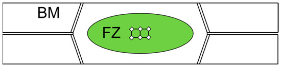
Figure 3.
Schematic positioning of the hardness measuring points (FZ: fusion zone, BM: base metal).
2.5. Mechanical Testing and Post-Failure Analysis
To compare the mechanical properties of spot welds in as-weld and tempered conditions, tensile–shear tests were carried out at a crosshead speed of 5 mm/min using an Instron universal testing machine. Figure 4 shows a typical load–displacement curve obtained from an experimental tensile–shear test along with the corresponding specimen gripped into the testing machine. To describe the mechanical performance of the welds, two important parameters were extracted from the corresponding load–displacement curves, including peak load (Pmax) and failure energy (Wmax). Pmax is measured as the peak point in the load–displacement curve, and Wmax is measured as the area under the load–displacement curve up to the peak load. An Olympus stereograph microscopy was used to examine the interfacial fracture surfaces after the tensile–shear test. Field emission scanning electron microscopy (FESEM) fractography was also conducted to determine the failure mechanisms of spot welds.
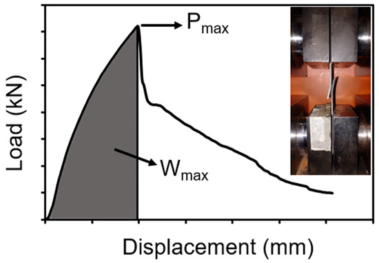
Figure 4.
Typical load–displacement curve of spot welds during tensile shear test.
3. Results and Discussion
3.1. Microstructure and Hardness Characteristics
Figure 5a illustrates the overall macrostructure of the AISI 1040 steel resistance spot weld made at 9 kA, indicating a microstructural gradient across the weldment. It can be divided into three different regions, including fusion zone (FZ), heat-affected zone (HAZ), and base metal (BM). It can be seen that FZ consists of columnar grains which grow directionally from the fusion boundary toward the weld centerline. Figure 5b shows a needle-like martensitic structure inside the columnar grains due to the quenching effect of water-cooled copper electrodes and the short welding cycle. Due to the formation of medium-carbon martensite in the FZ, the average hardness of this zone reached 610 HV, which is more than triple that of BM hardness (190 HV). Figure 5c shows the transition zone between HAZ and BM at a closer view. The HAZ is divided into inter-critical HAZ (ICHAZ) and upper-critical HAZ (UCHAZ). ICHAZ exhibits a dual-phase microstructure consisting of ferrite and martensite, while UCHAZ exhibits a fully martensitic structure with coarse grains. The hardness of UCHAZ was similar to that of FZ. Note that no significant phase transformation occurred in the sub-critical HAZ (SCHAZ) of the investigated steel since it has a ferritic–pearlitic structure.
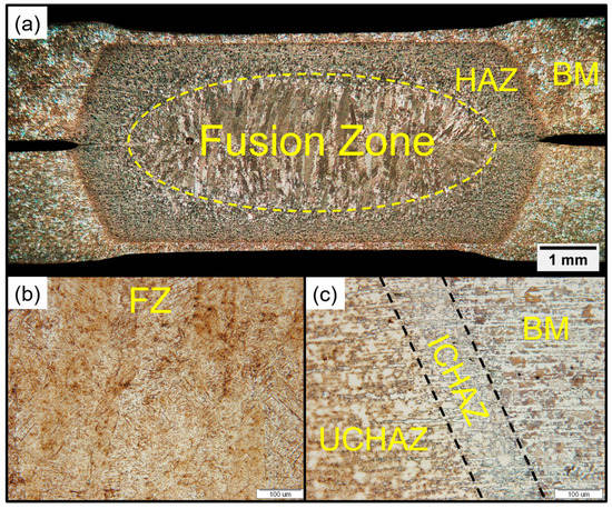
Figure 5.
(a) Overall macrostructure of AISI 1040 steel resistance spot weld made at 9 kA, (b) FZ microstructure, and (c) HAZ/BM microstructure.
Tempering spot welds at different tempering temperatures creates FZ microstructures consisting of martensite with different degrees of tempering. The degree of tempering is fundamentally determined by carbon diffusion, controlled by time and temperature. The latter one is variable in this study. Figure 6 shows the effect of tempering temperature on the extent of martensite tempering. FZ microstructure of the as-weld specimen consists of an entire lath martensitic structure (Figure 6a). Martensite laths have been somewhat recovered at 300 °C (Figure 6b). FZ microstructure of the PT7 specimen, tempered at 550 °C, shows fine dispersion of cementite precipitates (Figure 6c). Tempering at an even higher temperature (650 °C) leads to a coarsening of cementite particles, as seen in Figure 6d.
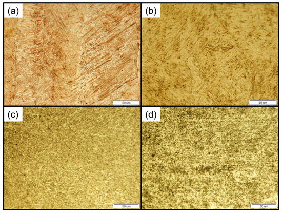
Figure 6.
Optical micrographs of FZ microstructure in (a) AW, (b) PT2, (c) PT7, and (d) PT9 conditions.
Figure 7a shows the average FZ hardness values for as-weld and tempered specimens. As expected, the FZ hardness decreased gradually by increasing the tempering temperature. The average FZ hardness of the PT9 Specimen, which is heavily tempered, became equal to the hardness of the base metal. Figure 7b illustrates the tempering temperature effect on the FZ hardness of AISI 1040 steel spot welds. It can be seen that the hardness drop is sharper in temperature ranges of 300–400 °C and 500–650 °C.
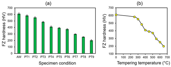
Figure 7.
(a) Variation in FZ hardness for different tempering conditions, and (b) effect of tempering temperature on average FZ hardness of AISI 1040 steel spot welds.
3.2. The Tensile–Shear Properties
Figure 8a shows the tensile shear load–displacement curves of the as-weld and tempered specimens. To avoid overlapping, the load–displacement curves of PT2, PT4, PT6, and PT8 specimens have not been plotted. The failure mode of all specimens under various conditions during the tensile shear test was interfacial or partial interfacial. As can be seen, tempering heat treatment and reduction in FZ hardness have a profound effect on the load–displacement characteristics of the welds. Peak load and failure energy values for each specimen condition were plotted in Figure 8b. The former parameter is an indication of weld strength, while the latter is an indication of the toughness and energy absorption capability of the weld. As illustrated, the mechanical properties of the as-weld condition in terms of Pmax and Wmax are the least compared to heat-treated specimens. By tempering at 250 °C, the mechanical properties start to enhance but interestingly decrease slightly at 300 °C. This loss in mechanical properties can be attributed to tempered martensite embrittlement (TME) at this temperature. TME is an irreversible phenomenon during tempering at 260–350 °C. There are conflicting reports in the literature regarding the precise mechanism of this phenomenon. The most common mechanism for TME is cementite precipitation on prior austenite grain boundaries or interlath boundaries due to the thermal decomposition of retained austenite. It has also been reported that the segregation of impurities such as phosphorous and nitrogen at prior austenite grain boundaries can increase the level of embrittlement. Therefore, it is suggested that the combined effects of these two factors must be considered for TME [19,20]. The susceptibility of medium carbon steels to this kind of embrittlement during tempering has been reported by several researchers [21,22,23,24].
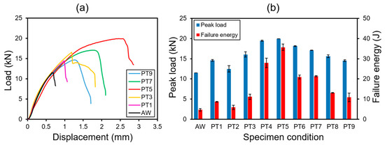
Figure 8.
(a) Load–displacement characteristics of the welds under various conditions, and (b) variation in mechanical properties in terms of peak load and failure energy for different tempering conditions.
As the tempering process continues at higher temperatures, the mechanical properties enhance sharply until they reach their optimum values at the tempering temperature of 450 °C (PT5 specimen). The average hardness of FZ in this condition was measured as 392 HV. However, the mechanical properties show a downward trend by further decreasing FZ hardness from 400 HV to 200 HV through tempering treatment. This conflicting behavior is due to the transition in the interfacial failure mechanism discussed in the following.
To better understand the effect of FZ hardness on the mechanical properties of the welds, another graph was plotted in Figure 9a, showing Pmax and Wmax versus FZ hardness. It can be seen that in FZ hardness less than 450 HV, peak load and FZ hardness have an almost linear relationship. This indicates that interfacial failure of spot welds with FZ hardness less than 450 HV would follow the hardness-based approach model in Equation (2). To confirm this point, the PIF of AISI 1040 steel spot welds, along with other data extracted from the literature [7,12,14,25,26,27,28,29,30,31,32,33,34,35,36,37,38], was plotted against D2HFZ in Figure 9b. In this plot, the D of the AISI 1040 spot welds is constant and equals 6.5 mm, while HFZ ranges from 200–410 HV. As illustrated, the data points of AISI 1040 spot welds with FZ hardness less than 450 HV lie approximately along the hardness-based model. It can be concluded that the interfacial failure driving force of these welds is the shear stress at the sheet/sheet interface.
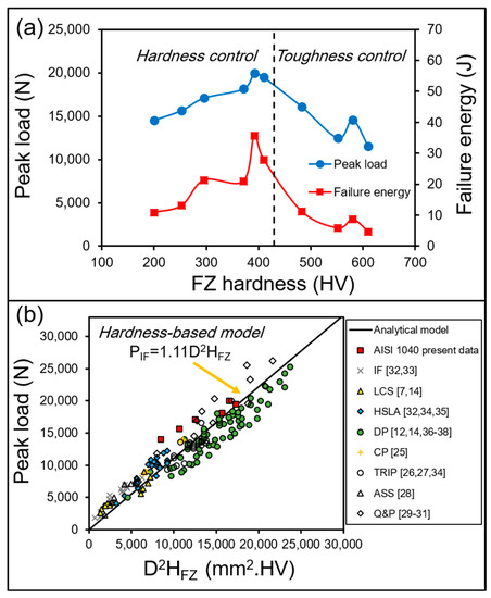
Figure 9.
(a) Peak load and failure energy vs. FZ hardness, and (b) correlation between failure load in interfacial failure mode (PIF) and D2HFZ in various automotive steel grades.
According to Figure 9a, there is no correlation between interfacial failure load and FZ hardness in those spot welds with hardness exceeding 450 HV (AW, PT1, PT2, and PT3 specimens). Therefore, interfacial failure of these spot welds can be potentially related to their FZ fracture toughness. Under this circumstance, stress concentration at the notch tip plays an important role in interfacial failure behavior. In RSWs, the sharp notch between the overlapped sheets acts as a pre-crack, making it a preferential site for crack propagation under loading conditions. Due to the hard martensitic phase ahead of the notch tip, the crack propagates in a brittle manner leading to low mechanical properties. Figure 10 shows the morphology of a sharp notch in the AISI 1040 resistance spot weld in AW condition.
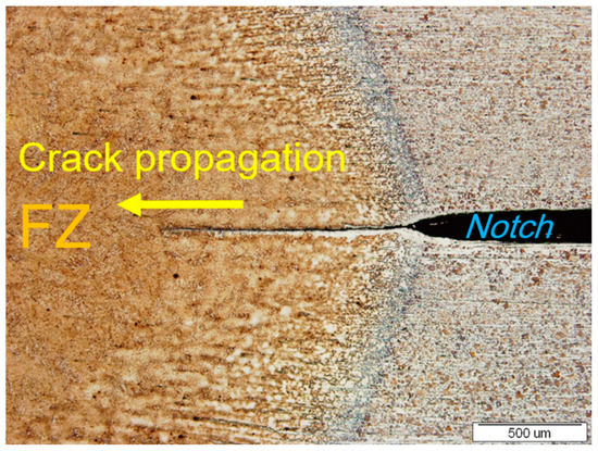
Figure 10.
Geometry of the sharp notch at the sheet/sheet interface of AISI 1040 steel spot weld.
The preceding discussions imply that conducting tempering heat treatment, whether in situ or ex situ, cannot constantly improve the tensile–shear properties due to the dual failure mechanisms during IF mode (ductile shear failure vs. rapid crack propagation). When spot welds fail via rapid crack propagation in interfacial mode, tempering heat treatment can enhance the mechanical properties by producing a tougher microstructure in the FZ. However, when spot welds fail via a ductile-shear mechanism in interfacial mode, tempering heat treatment can reduce the peak load of the welds by producing a softer microstructure in the FZ. Therefore, a deep understanding of interfacial failure mechanisms is necessary before designing a proper post-weld heat treatment to enhance mechanical properties. FESEM fractographic analysis in the following section can shed light on these failure mechanisms during IF mode.
3.3. Fracture Surface Analysis
Figure 11 shows the fracture surfaces of the welds under various tempering conditions taken by a stereo microscope. In as-weld and low-temperature-tempered specimens with high FZ hardness levels (AW, PT1, and PT2), the fracture surface has a shiny granular appearance and contains some secondary cracks. These secondary cracks in the fracture surface are attributed to the brittleness of the fracture path. On the other hand, the fracture surface of high-temperature-tempered specimens with low hardness levels (PT5, PT7, and PT9) have a ductile appearance with no sign of secondary cracks.
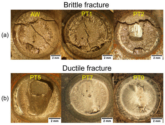
Figure 11.
Stereo micrographs of the fracture surfaces in various tempering conditions show both (a) brittle fracture and (b) ductile fracture.
To gain insight into the brittle and ductile fracture mechanisms, the fracture morphology of AW and PT specimens was examined by FESEM. Figure 12 shows the FESEM fractographs of AW, PT1, and PT2 specimens, which failed in a brittle manner due to high levels of weld hardness. The fracture surface of these specimens is predominantly intergranular, which is recognizable by its rock candy appearance. This fracture type occurs by decohision along weakened grain boundaries and is typically associated with tempered martensite embrittlement (TME) or temper embrittlement (TE) in medium carbon steels [39]. Because the AW specimens, experiencing no treatment, also failed in an intergranular fashion, the incidence of such fracture can be related to quench embrittlement. This embrittlement is found in quenched steels with carbon content as low as 0.5% due to transformational and residual stresses developed during the quenching process [40,41]. The fracture surface of the PT2 specimen, which is partially tempered at 250 °C, appears as a mixture of intergranular and micro void coalescence (Figure 12e,f). On the other hand, the fracture surface of the PT3 specimen that had undergone TME at 300 °C showed intergranular fracture along with transgranular fracture, including cleavage facets (Figure 12h,i). This can be attributed to formation of interlath cementite due to thermal decomposition of interlath retained austenite during tempering. In summary, the interfacial failure of those welds with high hardness values (more than 450 HV) has a brittle nature and is controlled by the fracture toughness of the fusion zone.
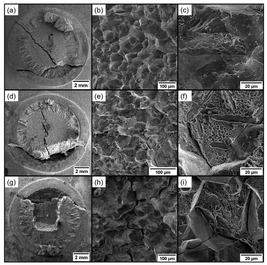
Figure 12.
FESEM images of the fracture surface of (a–c) as-weld specimen, (d–f) PT2 specimen tempered at 250 °C, and (g–i) PT3 specimen tempered at 300 °C.
Figure 13 shows the FESEM fractographs of high-temperature-tempered specimens (PT5, PT7, and PT9), which failed in a ductile manner due to low FZ hardness values (200–400 HV). The fracture surface of these specimens is predominately covered by elongated dimples created by microvoid coalescence. The elongated dimples indicate that interfacial failure of these welds occurred by the shear plastic deformation mechanism controlled by the shear strength of the FZ.
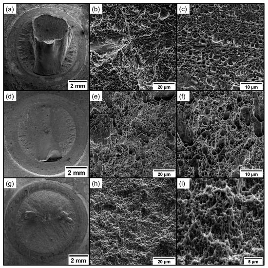
Figure 13.
FESEM images of the fracture surface of (a–c) PT5 specimen tempered at 450 °C, (d–f) PT7 specimen tempered at 550 °C, and (g–i) PT9 specimen tempered at 650 °C.
4. Conclusions
Interfacial failure of resistance spot welds during the tensile–shear loading is a competitive process between ductile shear failure and rapid crack propagation. This paper investigated the effect of FZ hardness value on the interfacial failure mechanism transition of resistance spot welds. Various welds of the same nugget size with various FZ hardness levels were produced. It is found that decreasing fusion zone hardness from 610 HV down to 400 HV enhances the interfacial failure load and failure energy of the spot welds due to improvement in FZ fracture toughness. However, further reduction in fusion zone hardness from 400 HV to 200 HV shows an inverse effect on peak load and failure energy. This contradicting behavior is attributed to the transition in the interfacial failure mechanism from ductile shear failure to rapid crack propagation. It was found that there is a critical FZ hardness beyond which the interfacial failure mechanism transitions from ductile shear failure to rapid crack propagation. The critical FZ hardness depends on the level of nugget toughness. In this paper, the interfacial failure of spot welds with FZ hardness higher than 450 HV shows a brittle intergranular fracture surface indicating rapid crack growth. FZ fracture toughness plays a major role in determining interfacial failure strength in this situation. In contrast, a fracture surface covered by elongated dimples was observed for spot welds with FZ hardness lower than 450 HV, confirming the incidence of shear plastic deformation during interfacial failure. In this situation, interfacial failure strength is controlled by FZ hardness.
Author Contributions
Conceptualization, M.P.; methodology, N.N.; investigation, N.N.; writing—original draft preparation, N.N.; writing—review and editing, M.P., Supervision, M.P. All authors have read and agreed to the published version of the manuscript.
Funding
This research received no external funding.
Institutional Review Board Statement
Not applicable.
Informed Consent Statement
Not applicable.
Data Availability Statement
The datasets used and/or analyzed during the current study are available from the corresponding author upon reasonable request.
Conflicts of Interest
The authors declare no conflict of interest.
Nomenclature
| AHSS | Advanced high-strength steel |
| RSW | Resistance spot welding |
| FZ | Fusion zone |
| HAZ | Heat affected zone |
| UCHAZ | Upper-critical heat-affected zone |
| ICHAZ | Inter-critical heat-affected zone |
| SCHAZ | Sub-critical heat-affected zone |
| BM | Base metal |
| LME | Liquid metal embrittlement |
| IF | Interfacial failure |
| AW | As weld condition |
| PT | Post-weld tempered condition |
| TME | Tempered martensite embrittlement |
| TE | Temper embrittlement |
| AISI | American Iron and Steel Institute |
| IF | Interstitial Free steel |
| LCS | Low carbon steel |
| HSLA | High strength low alloy steel |
| DP | Dual-phase steel |
| CP | Complex phase steel |
| TRIP | Transformation-induced plasticity steel |
| ASS | Austenitic stainless steel |
| Q&P | Quench and partitioning steel |
| Interfacial failure load (N) | |
| Ultimate shear strength of the fusion zone (MPa) | |
| Hardness of the fusion zone (HV) | |
| Fracture toughness of the fusion zone (MPa.m0.5) | |
| D | Nugget diameter (mm) |
| t | Sheet thickness (mm) |
| Pmax | Peak load (N) |
| Wmax | Failure energy (J) |
References
- Czerwinski, F. Current Trends in Automotive Lightweighting Strategies and Materials. Materials 2021, 14, 6631. [Google Scholar] [CrossRef]
- Tisza, M. Three Generations of Advanced High Strength Steels in the Automotive Industry. In Vehicle and Automotive Engineering 3; Lecture Notes in Mechanical Engineering; Springer: Singapore, 2021; Volume 22, pp. 81–94. [Google Scholar] [CrossRef]
- Gupta, M.K.; Singhal, V. Review on Materials for Making Lightweight Vehicles. Mater. Today Proc. 2022, 56, 868–872. [Google Scholar] [CrossRef]
- De Moor, E. Advanced High-Strength Sheet Steels for Automotive Applications. In High-Performance Ferrous Alloys; Springer: Cham, Swizerland, 2021; pp. 113–151. [Google Scholar]
- Tisza, M. Development of Lightweight Steels for Automotive Applications. In Engineering Steels and High Entropy-Alloys; IntechOpen: London, UK, 2020. [Google Scholar]
- Soomro, I.A.; Pedapati, S.R.; Awang, M. A Review of Advances in Resistance Spot Welding of Automotive Sheet Steels: Emerging Methods to Improve Joint Mechanical Performance. Int. J. Adv. Manuf. Technol. 2022, 118, 1335–1366. [Google Scholar] [CrossRef]
- Pouranvari, M.; Asgari, H.R.; Mosavizadch, S.M.; Marashi, P.H.; Goodarzi, M. Effect of Weld Nugget Size on Overload Failure Mode of Resistance Spot Welds. Sci. Technol. Weld. Join. 2007, 12, 217–225. [Google Scholar] [CrossRef]
- Pouranvari, M.; Marashi, S.P.H. Critical Review of Automotive Steels Spot Welding: Process, Structure and Properties. Sci. Technol. Weld. Join. 2013, 18, 361–403. [Google Scholar] [CrossRef]
- Den Uijl, N.; Okada, T.; Moolevliet, T.; Mennes, A.; Van Der Aa, E.; Uchihara, M.; Smith, S.; Nishibata, H.; Van Der Veldt, T.; Fukui, K. Performance of Resistance Spot-Welded Joints in Advanced High-Strength Steel in Static and Dynamic Tensile Tests. Weld. World 2012, 56, 51–63. [Google Scholar] [CrossRef]
- Wei, S.; Li, Y.; Lu, S. Similar and Dissimilar Resistance Spot Weldability of Q&P980 and TWIP1180 Steels. Sci. Technol. Weld. Join. 2022, 27, 77–83. [Google Scholar]
- Akulwar, S.; Akela, A.; Satish Kumar, D.; Ranjan, M. Resistance Spot Welding Behavior of Automotive Steels. Trans. Indian Inst. Met. 2021, 74, 601–609. [Google Scholar] [CrossRef]
- Pouranvari, M.; Marashi, S.P.H. Key Factors Influencing Mechanical Performance of Dual Phase Steel Resistance Spot Welds. Sci. Technol. Weld. Join. 2010, 15, 149–155. [Google Scholar] [CrossRef]
- Chuko, W.L.; Gould, J.E. Development of Appropriate Resistance Spot Welding Practice for Transformation-Hardened Steels. Weld. J. 2002, 81, 1–7. [Google Scholar]
- Pouranvari, M.; Marashi, S.P.H.; Safanama, D.S. Failure Mode Transition in AHSS Resistance Spot Welds. Part II: Experimental Investigation and Model Validation. Mater. Sci. Eng. A 2011, 528, 8344–8352. [Google Scholar] [CrossRef]
- Zhang, S.; DiGiovanni, C.; He, L.; Zhou, N.Y. Weld Hardness Ratio and Liquid Metal Embrittlement Crack’s Detrimental Effect on Resistant Spot Weld Strength. Sci. Technol. Weld. Join. 2021, 26, 58–67. [Google Scholar] [CrossRef]
- Pouranvari, M. Susceptibility to Interfacial Failure Mode in Similar and Dissimilar Resistance Spot Welds of DP600 Dual Phase Steel and Low Carbon Steel during Cross-Tension and Tensile-Shear Loading Conditions. Mater. Sci. Eng. A 2012, 546, 129–138. [Google Scholar] [CrossRef]
- Pouranvari, M.; Marashi, S.P.H. Failure Mode Transition in AHSS Resistance Spot Welds. Part I. Controlling Factors. Mater. Sci. Eng. A 2011, 528, 8337–8343. [Google Scholar] [CrossRef]
- Pouranvari, M. Understanding the Factors Controlling the Interfacial Failure Strength of Advanced High-Strength Steel Resistance Spot Welds: Hardness vs. Fracture Toughness. Sci. Technol. Weld. Join. 2018, 23, 520–526. [Google Scholar] [CrossRef]
- Horn, R.M.; Ritchie, R.O. Mechanisms of Tempered Martensite Embrittlement in Low Alloy Steels. Metall. Trans. A 1978, 9, 1039–1053. [Google Scholar] [CrossRef]
- Peters, J.A.; Bee, J.V.; Kolk, B.; Garrett, G.G. On the Mechanisms of Tempered Martensite Embrittlement. Acta Metall. 1989, 37, 675–686. [Google Scholar] [CrossRef]
- Euser, V.K.; Williamson, D.L.; Findley, K.O.; Clarke, A.J.; Speer, J.G. The Role of Retained Austenite in Tempered Martensite Embrittlement of 4340 and 300-M Steels Investigated through Rapid Tempering. Metals 2021, 11, 1349. [Google Scholar] [CrossRef]
- Zia-Ebrahimi, F.; Krauss, G. Mechanisms of Tempered Martensite Embrittlement in Medium-Carbon Steels. Acta Metall. 1984, 32, 1767–1778. [Google Scholar] [CrossRef]
- Costa, J.E.; Thompson, A.W. Effect of Hydrogen on Fracture Behavior of a Quenched and Tempered Medium-Carbon Steel. Metall. Trans. A 1981, 12, 761–771. [Google Scholar] [CrossRef]
- Clarke, A.J.; Klemm-Toole, J.; Clarke, K.D.; Coughlin, D.R.; Pierce, D.T.; Euser, V.K.; Poplawsky, J.D.; Clausen, B.; Brown, D.; Almer, J.; et al. Perspectives on Quenching and Tempering 4340 Steel. Metall. Mater. Trans. A 2020, 51, 4984–5005. [Google Scholar] [CrossRef]
- Kong, J.P.; Han, T.K.; Chin, K.G.; Park, B.G.; Kang, C.Y. Effect of Boron Content and Welding Current on the Mechanical Properties of Electrical Resistance Spot Welds in Complex-Phase Steels. Mater. Des. 2014, 54, 598–609. [Google Scholar] [CrossRef]
- Park, S.-S.; Choi, Y.-M.; Nam, D.-G.; Kim, Y.-S.; Yu, J.-H.; Park, Y.-D. Evaluation of Resistance Spot Weld Interfacial Fractures in Tensile-Shear Tests of TRIP 1180 Steels. J. Weld. Join. 2008, 26, 81–91. [Google Scholar] [CrossRef]
- Oikawa, H.; Murayama, G.; Hiwatashi, S.; Matsuyama, K. Resistance Spot Weldability of High Strength Steel Sheets for Automobiles and the Quality Assurance of Joints. Weld. World 2007, 51, 7–18. [Google Scholar] [CrossRef]
- Marashi, P.; Pouranvari, M.; Sanaee, S.M.H.; Abedi, A.; Abootalebi, S.H.; Goodarzi, M. Relationship between Failure Behaviour and Weld Fusion Zone Attributes of Austenitic Stainless Steel Resistance Spot Welds. Mater. Sci. Technol. 2008, 24, 1506–1512. [Google Scholar] [CrossRef]
- Shojaee, M.; Midawi, A.R.H.; Barber, B.; Ghassemi-armaki, H.; Worswick, M.; Biro, E. Mechanical Properties and Failure Behavior of Resistance Spot Welded Third-Generation Advanced High Strength Steels. J. Manuf. Process. 2021, 65, 364–372. [Google Scholar] [CrossRef]
- Chen, T.; Ling, Z.; Wang, M.; Kong, L. Effect of a Slightly Concave Electrode on Resistance Spot Welding of Q&P1180 Steel. J. Mater. Process. Technol. 2020, 285, 116797. [Google Scholar] [CrossRef]
- Nadimi, N.; Yadegari, R.; Pouranvari, M. Resistance Spot Welding of Quenching and Partitioning (Q&P) Third-Generation Advanced High-Strength Steel: Process—Microstructure—Performance. Metall. Mater. Trans. A 2023, 54, 577–589. [Google Scholar]
- Ghassemi-Armaki, H.; Bhat, S.; Kelley, S.; Sadagopan, S. Quasi-Static Spot Weld Strength of Advanced High-Strength Sheet Steels. Weld. J. 2017, 96, 104–112. [Google Scholar]
- Rao, S.S.; Chhibber, R.; Arora, K.S.; Shome, M. Resistance Spot Welding of Galvannealed High Strength Interstitial Free Steel. J. Mater. Process. Technol. 2017, 246, 252–261. [Google Scholar] [CrossRef]
- Burgmann, P.; Cobb, S.; Davis, J.; Miller, M.; Smith, M.; Findley, K.O.; Liu, S. Weldability, Processing, Microstructure and Mechanical Behavior Relationships in Advanced High-Strength Steel. Iron Steel Technol. 2010, 7, 76–85. [Google Scholar]
- Pouranvari, M. On the Failure Mode of Resistance Spot Welded HSLA 420 Steel. Arch. Metall. Mater. 2013, 58, 67–72. [Google Scholar] [CrossRef]
- Jaber, H.L.; Pouranvari, M.; Salim, R.K.; Hashim, F.A.; Marashi, S.P.H. Peak Load and Energy Absorption of DP600 Advanced Steel Resistance Spot Welds. Ironmak. Steelmak. 2017, 44, 699–706. [Google Scholar] [CrossRef]
- Baltazar Hernandez, V.H. Effects of Martensite Tempering on HAZ-Softening and Tensile Properties of Resistance Spot Welded Dual-Phase Steels. Ph.D. Thesis, University of Waterloo, Waterloo, ON, Canada, 2010. [Google Scholar]
- Hernandez, B.V.H.; Kuntz, M.L.; Khan, M.I.; Zhou, Y. Influence of Microstructure and Weld Size on the Mechanical Behaviour of Dissimilar AHSS Resistance Spot Welds. Sci. Technol. Weld. Join. 2008, 13, 769–776. [Google Scholar] [CrossRef]
- Krauss, G. Deformation and Fracture in Martensitic Carbon Steels Tempered at Low Temperatures. Metall. Mater. Trans. B 2001, 32, 205–221. [Google Scholar] [CrossRef]
- Krauss, G. Heat Treated Martensitic Steels: Microstructural Systems for Advanced Manufacture. ISIJ Int. 1995, 35, 349–359. [Google Scholar] [CrossRef]
- De Campos Franceschini Canale, L.; Mesquita, R.A.; Totten, G.E. Failure Analysis of Heat Treated Steel Components; ASM International: Almere, The Netherlands, 2008; ISBN 9780871708687. [Google Scholar]
Disclaimer/Publisher’s Note: The statements, opinions and data contained in all publications are solely those of the individual author(s) and contributor(s) and not of MDPI and/or the editor(s). MDPI and/or the editor(s) disclaim responsibility for any injury to people or property resulting from any ideas, methods, instructions or products referred to in the content. |
© 2023 by the authors. Licensee MDPI, Basel, Switzerland. This article is an open access article distributed under the terms and conditions of the Creative Commons Attribution (CC BY) license (https://creativecommons.org/licenses/by/4.0/).