Article

Study on Simulation of Mold Filling and Solidification Characteristics of Hypereutectic High-Chromium Cast Iron by Lost Foam Suspension Casting

Key Laboratory of Advanced Functional Materials, Ministry of Education, Department of Materials Science and Engineering, Beijing University of Technology, Beijing 100124, China
*
Author to whom correspondence should be addressed.
Metals 2023, 13(10), 1761; https://doi.org/10.3390/met13101761
Submission received: 18 August 2023 / Revised: 22 September 2023 / Accepted: 25 September 2023 / Published: 17 October 2023
(This article belongs to the Special Issue Solidification and Casting of Metals and Alloys)

Abstract

:
In this paper, the finite element software ProCAST version 14.5 was used to simulate the temperature field, flow field and defect prediction in the filling and solidification process of hypereutectic high-chromium cast iron. The effects of pouring temperature, negative pressure and the amount of suspension agent added during the technological process were explored. The optimum process parameters were presented. It was found that the suspension agent has a certain hindrance to the filling process, but the filling process remains stable. In the solidification stage, 89.4% of the suspension agent melted, resulting in a relative supercooling degree of 50 °C, which had a certain chilling effect and improved the solidification rate.

1. Introduction

Hypereutectic high-chromium cast iron contains a large number of M7C3 primary carbides which are supported and protected by the matrix so that it has better wear resistance than traditional eutectic and hypoeutectic alloys. During the solidification process of hypereutectic high-chromium cast iron, coarse primary carbides are formed, which reduces toughness. Defects such as cracks and shrinkage holes also easily occur during casting production, which restricts its application and promotion to a certain extent [1]. In order to improve the toughness of hypereutectic high-chromium cast iron and improve its comprehensive mechanical properties, domestic and foreign researchers have done a lot of research on refining primary carbides; the main methods include metamorphism and inoculation [2,3,4,5], heat treatment [6,7,8,9,10], pulsed current [11,12] treatment, etc. Previous studies on refining primary carbides of hypereutectic high-chromium cast iron have also been carried out by our research group. The studies have shown that appropriate modification treatment (RE-Mg), element regulation and heat treatment are helpful in refining primary carbides. It has been found that refining primary carbide combined with heat treatment and alloying can improve the corrosion and wear resistance of hypereutectic high-chromium cast iron [13].
Suspension casting technology (also known as micro-cooling) is a new casting method proposed by Soviet experts in the 1960s. This is a casting method in which a certain amount of metal powder is added to the metal flow as a suspension agent when pouring liquid metal into the mold [14]. The suspension agent is extremely fine and plays an internal chilling role, while the alloying elements contained in it play a metamorphic role, promoting heterogeneous nucleation and thus refining the crystallization structure, improving metal density, reducing casting defects such as shrinkage porosity, shrinkage porosity, segregation and hot cracking and improving mechanical properties [15]. Suspension casting technology is widely used in a variety of materials such as aluminum matrix composites [16] like cast steel, cast iron, etc. to improve the hardness, wear resistance and corrosion resistance of castings and to refine the microstructure. The important process parameters of suspension casting include the composition and quantity of the suspension agent and the size of the particles. Li Qiushu et al. [17] studied the effect of suspension casting on the microstructure and mechanical properties of high-chromium white cast iron by adding 66%Cr-Fe alloy as a suspension agent using the punching method. The results showed that the microstructure of high-chromium cast iron can be significantly improved by adding the suspension agent (adding 1.5 wt%); the continuous network carbide becomes a fine and uniform granular carbide, the impact toughness is increased by 20–30% and the wear resistance is increased by 20%. Dai Binyu [18] used iron powder as a suspension agent to manufacture a high-chromium cast iron refractory brick mold using the method of suspension casting with the agent added in metal flow. When the amount of suspension agent was 0.5~1 wt%, the microstructure of the high-chromium cast iron was refined, the carbide was changed from a continuous mesh to an intermittent form and the wear-resistant performance and service life were improved. Zhi Xiaohui et al. [19] found that the addition of a 2.1% high carbon steel suspension agent outside the mold could improve the microstructure characteristics of a cast hypereutectic Fe-20Cr-4C alloy and obtain fine and uniform carbides. The average size of the primary carbides was reduced from 30 μm to 5.7 μm, and the impact toughness was improved from 2.5 J/cm2 to 5.5 J/cm2. It can be seen that suspension casting can effectively refine the primary carbides of hypereutectic high-chromium cast iron and improve its toughness and wear resistance.
Lost foam casting (LFC) or expendable pattern casting (EPC), also known as vacuum-evaporative pattern casting, is a nearly unlimited, precise, vacuum seal casting and solid casting process grafted from new technology and representing the developmental direction of casting methods in the 21st century. It is a precision casting method that uses foam to make a solid shape of exactly the same structure and size of the parts. After dipping in refractory adhesive paint and drying, dry sand modeling and vibration compaction is carried out and the liquid metal is poured to make the shape disappear under heat and gasification so as to obtain metal parts with the same shape [20,21]. The important process parameters affecting the microstructure and properties of castings in the EPC process include the pouring temperature and negative pressure. Suyitno et al. [22] studied the relationship between the fluidity, porosity and surface roughness of gray cast iron and pouring temperature in the lost foam casting process. The experimental results show that the fluidity, porosity and surface roughness of gray cast iron increase with an increase in the casting temperature within the temperature range of 1300–1400 °C. The higher the pouring temperature, the lower the viscosity of the liquid metal and the more serious the turbulence phenomenon during pouring. The turbulence makes it easy to enclose the gas into the liquid metal, so the porosity of the casting increases. Xie Mingguo et al. [23] studied the influence of vacuum conditions on the solidification structure of hypoeutectic gray cast iron in lost foam casting and found that the influence of vacuum conditions on the filling process was greater than that on the solidification process, and the microstructure of the thin-wall region of the casting was more sensitive to the influence of vacuum conditions. Wu Guohua et al. [24] studied the effect of vacuum degree on the porosity of aluminum alloy cast by lost foam casting. These studies show that lower negative pressure is beneficial in reducing the porosity of aluminum alloy casting.
In this experiment, the method of preparing composite materials by lost foam casting was used for reference [21,25,26], and the process of suspension casting and lost foam casting was combined. With the help of the foam, the suspension agent could be more evenly distributed in the casting, which could refine the microstructure of cast iron and improve the mechanical properties such as hardness and wear resistance of the material [27,28,29]. Liu Gensheng et al. [27] studied the effect of adding 89%Cr-Fe as a suspension agent of lost foam casting low chromium white cast iron on its performance and found that the matrix microstructure changed from pearlite to sortenite and tristenite and the pearlite sheet spacing decreased. With the increase of the Cr/C ratio, the carbide type changes from M3C to M7C3, and the wear resistance is the best when the addition amount is 2.0–2.5 wt%, which is 35% higher than that of the conventional lost foam casting process.
At present, although the simulation of the casting filling and solidification process using large-scale commercial software such as ProCAST has been relatively mature [30,31,32,33,34], the lost foam suspension casting technology has been widely used in the development and production of various types of wear-resistant and heat-resistant iron and steel castings and has achieved good results [28,29]. However, there is no report on the numerical simulation of lost foam suspension casting. In this experiment, the numerical simulation method was introduced into the research process of lost foam suspension casting and the filling and solidification characteristics of hypereutectic high-chromium cast iron were simulated and analyzed, providing reference data for the popularization and application of hypereutectic high-chromium cast iron.

2. Mathematical Model

The flow process of casting metal filling includes the energy loss of the liquid metal itself and the flow and solidification process of the liquid metal under non-constant temperature conditions [35,36]. The filling flow process of liquid metal follows three conservation laws: mass conservation, momentum conservation and energy conservation. The continuity equation, momentum equation (Navier–Stokes equation), volume function equation and the energy equation are usually used to describe this process, as shown in Formulas (1)–(4). The actual pouring process of liquid metal is very complicated because of the complex and diverse design structure of the pouring system. The turbulent flow factors of liquid metal make the filling mostly turbulent, so the calculation of turbulent flow treatment needs to be introduced in the simulation process. At present, the numerical simulation of the casting mold filling process mostly adopts the SOLA-VOF method. SOLA is an iterative method to solve the velocity field-pressure field, and VOF is a method to deal with free surfaces (short for volume function), as shown in Formulas (5)–(7).
Mass conservation equation:
D = u x + v y + w z = 0
Momentum conservation equation (N–S equation):
ρ u t + u u x + v u y + w u z = p x + ρ g x + μ 2 u
ρ v t + u v x + v v y + w v z = p x + ρ g y + μ 2 v
ρ w t + u w x + v w y + w w z = p x + ρ g z + μ 2 w
Here, D is the degree of dispersion and u, v and w are the components (m/s) of the velocity vector in the X, Y and Z directions of the coordinate system. P is the pressure per unit density (Pa). μ is the kinematic viscosity (m2/s). g is the gravitational acceleration (m/s2). ∇2 is the Laplace operator. ρ is the metal fluid density (kg/m3).
Energy equation:
ρ c T t + ρ c u T x + ρ c v T y + ρ c w T z = x k T x + y k T y + z k T z + S
When the volume function method is used to track the movement of the free surface, it is also necessary to solve the F-function equation. When the F-value is one, the grid is in a full state and there is no free surface; when the F-value is zero, the grid is empty and there is no free surface; when the F-value is between zero and one, the grid is semi-full and there is a free interface in the grid. F function equation:
f t + u f x + v f y + w f z = 0
The reasonable amount of suspension agent added in suspension casting can be calculated according to the following formula [37]:
S = 100 t 1 1 0.0144 C t 1 R t 2 + 39 t 2
Here, t1 is the pouring temperature and t2 is the liquidus temperature.

3. Experimental Method

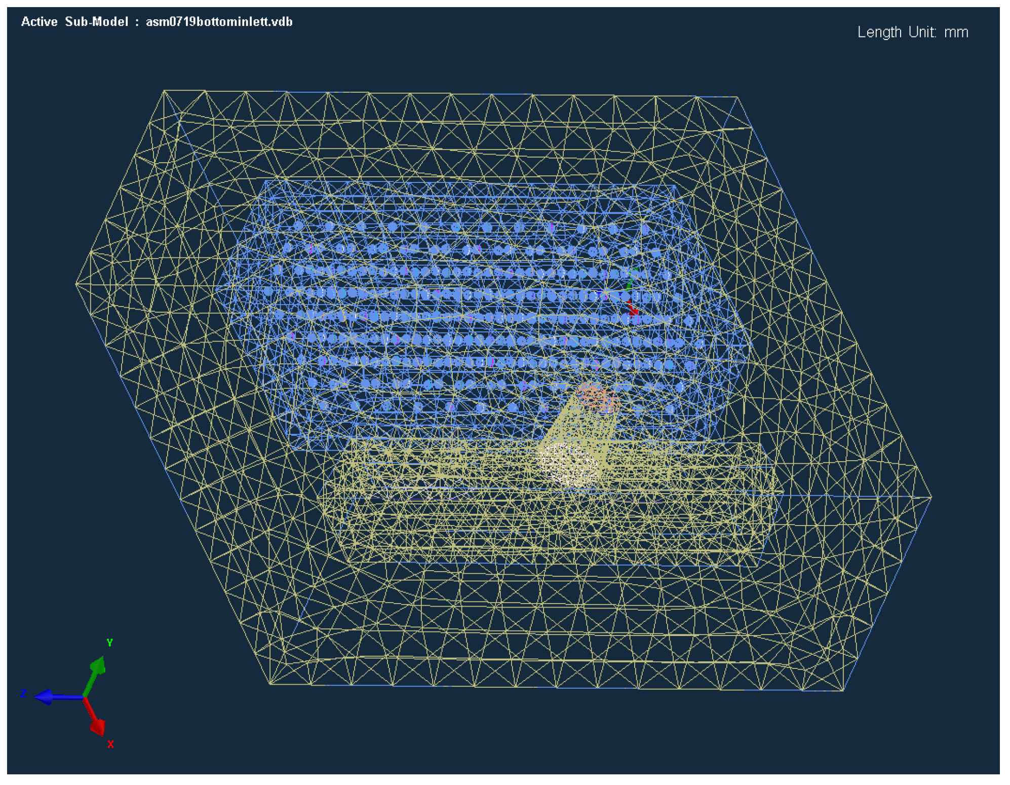
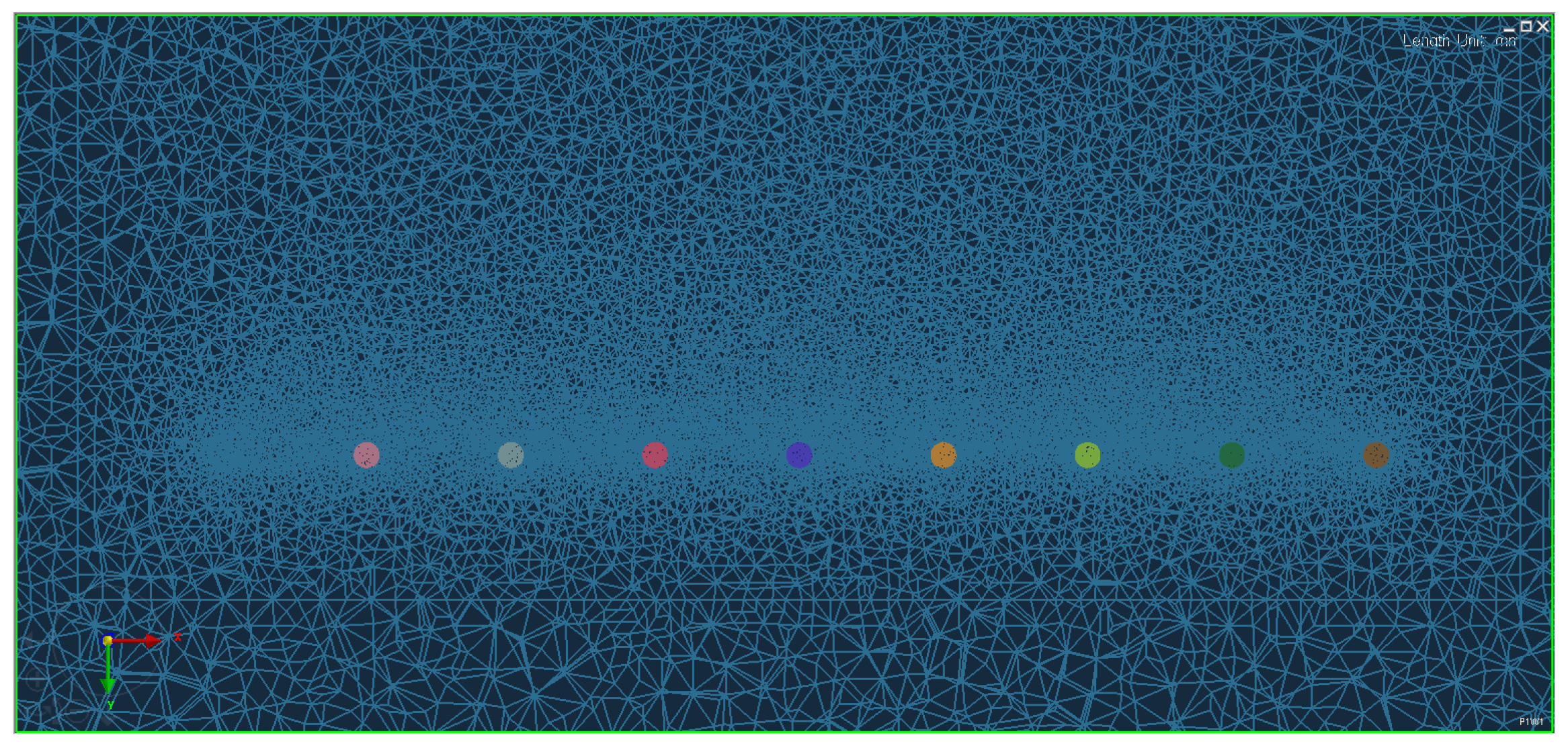
3.1. Three-Dimensional Modeling and Mesh Division

In order to reduce the calculation time and improve the calculation efficiency in the process of studying the characteristics of the lost foam suspension casting technology by using the simulation method, a simple cuboid ingot was selected as the experimental research object. Creo 4.0 software was used to model castings, suspensions and pouring systems. The suspensions were distributed evenly in cuboid castings with a metal ball 2 mm in diameter. Both the size of the suspension agent and the size of the mesh division are very important. In actual production, the size of the suspension agent is usually between 0.5–2.5 mm. If the size is too small, a finer mesh will be needed in mesh division to slow down the calculation speed; if the size is too large, the performance improvement effect in actual production will be poor. The size of the casting is 100 mm × 50 mm × 32.5 mm, and the size of the mold is 140 mm × 125 mm × 58 mm. The bottom casting system design is adopted. The assembly is imported into the MeshCAST module in ProCAST 14.5 software for verification, generation and repair of the surface mesh and generation and inspection of the body mesh. The meshing model is shown in Figure 1, in which there is a transitional area of mesh size between the body mesh of the suspension agent and the casting, as shown in Figure 2.

3.2. Material Selection

In this experiment, 35Cr-4C hypereutectic high-chromium cast iron was used, which has high hardness and excellent wear resistance. The chemical composition of hypereutectic high-chromium cast iron is shown in Table 1 and its material properties were calculated by ProCAST.

3.3. Simulation Parameter Settings

Simulation parameters are the basis for the numerical simulation process, and the reliability of the simulation results depends on the rationality of the selection of simulation parameters. ProCAST 14.5 software was innovatively used in this experiment to study the process characteristics of the lost foam suspension casting, so the setting of simulation parameters and boundary conditions was very important. The key simulation parameters in lost foam suspension casting included pouring temperature, pouring speed, negative pressure, type of suspension agent, addition amount of suspension agent and particle size of suspension agent. This experiment focused on the influence of pouring temperature, negative pressure and the amount of suspension agent on the process and process defects.
The initial and boundary conditions were set as follows: The liquid metal temperature (that is, the initial temperature set in the pouring cup) was the pouring temperature (1480 °C, 1540 °C and 1600 °C). TiFe particles with a diameter of 2 mm were used as the suspension agent. The casting material was sand permeable foam specifcally for lost mold casting in ProCAST. The casting and runner were made of foam material and the sprue cup was set as alloy. The initial temperature of the foam material, mold and suspension agent should be 25 °C. The heat transfer coefficient between the mold and the liquid metal was 400 W/m2·K, and the heat transfer coefficient between the liquid metal and the suspension agent was 2000 W/m2·K. In the actual casting process, the heat transfer coefficient should vary with time, but in this experiment, the heat transfer coefficient was simplified to a constant value for the convenience of the research. The outside of the mold and gate were set to air cooling conditions, and the negative pressure was set by creating a pressure difference between the outside of the mold and the outside of the gate. The negative pressure values could be 0.04 MPa and 0.06 MPa. The casting speed was set to 2 kg/s.
It is necessary to pay attention to the special situation of interface heat transfer setting in the simulation parameter setting of lost die casting. EQUIV (equivalent type) is usually used in the heat exchange process between two identical materials, where the two interface units share a common node between the interface and there is a continuous temperature field at the interface. In this experiment, although the casting system and casting were set as alloy and foam respectively, with different material types, in order to ensure that the real situation of heat exchange between liquid metal and foam materials could be simulated, the interface between the two was usually set as EQUIV type, so that the temperature field during simulation was continuous.

4. Results and Discussions

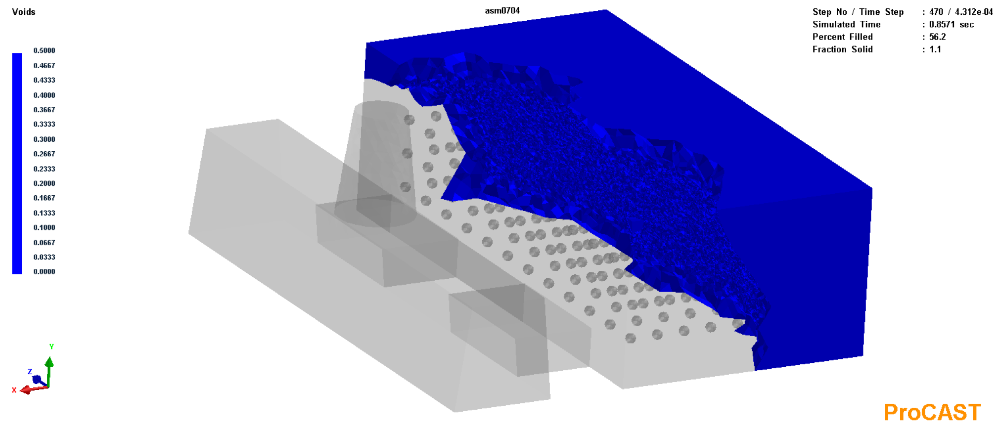
4.1. Shrinkage Porosity Simulation

The solidus method, critical solid fraction method, temperature gradient method and Niyama( G / R )method were proposed to effectively predict casting defects generated during the solidification [38]. In this experiment, the Niyama( G / R ) method of ProCAST software was used to predict the shrinkage and porosity in castings. By comparing the results of different negative pressure, casting temperature and the amount of suspension agent, the optimal process parameters were selected for the subsequent analysis of the filling and solidification process.
The role of vacuum-negative pressure is to fix the dry sand in the process of pouring and solidification and to form an exhaust cycle, so that the gas generated by foam pyrolysis and gasification during the pouring process is discharged to the outside of the mold, thereby reducing the casting defects. Zhao Zewen et al. [39] found through an orthogonal experiment that in the lost foam casting process of cast iron with a bottom casting system, the negative pressure had a greater impact on the shrinkage and porosity results than the pouring temperature. According to this conclusion, the influence of negative pressure on the results of porosity and porosity reduction was given priority in this experiment.
In this experiment, the results of shrinkage porosity under the negative pressure of 0.04 MPa and 0.06 MPa were compared, as shown in Figure 3a,b. It can be found from the results that a certain size of porosity and shrinkage holes will be produced at each suspension agent particle, but these porosity and shrinkage holes are very small or even negligible in the actual production. It is speculated that the large shrinkage and porosity of the suspension agent in the simulation software is because the simulation software cannot take into account the exchange of metal materials in different regions. Without considering the shrinkage porosity at the suspension agent, the shrinkage porosity of the casting with a vacuum degree of 0.06 MPa (0.0008 cm3) is significantly smaller than that of the casting with a vacuum degree of 0.04 MPa (0.0085 cm3). Appropriately increasing the negative pressure (from 0.02 MPa to 0.05 MPa) can effectively eliminate dimensional deformation, box collapse, slag inclusion, sand fusion and other defects of castings, shorten casting time and improve casting quality [40].
The pouring temperature of the lost foam suspension casting will also affect the shrinkage and porosity results. Appropriately increasing the pouring temperature will help improve the liquid metal flow, but too high a pouring temperature will increase the liquid shrinkage of the casting and the volume of shrinkage and porosity formed inside the casting [41]. The casting temperature of hypereutectic high-chromium cast iron is generally about 1400 °C, considering that the casting temperature of lost foam castings is generally about 80 °C higher than that of ordinary sand casting, and the presence of a suspension agent will hinder the flow of the liquid metal, so 1480 °C, 1540 °C and 1600 °C were selected in this experiment. When other conditions are the same, the shrinkage porosity is the lowest when the pouring temperature is 1540 °C.
In this experiment, 0.5%, 0.75% and 1% of suspension additives were selected for discussion. By comparing the results of shrinkage porosity, it was found that in the range of 0.5–1%, the larger the amount of suspension agent added, the lower the shrinkage porosity. When the amount of suspension agent added reaches 1%, the shrinkage porosity reaches 3 × 10⁻⁵ cm3, which can be said that the shrinkage porosity of simple cuboid castings is almost eliminated.
In summary, the optimal process parameters within the scope of this experiment are a negative pressure of 0.06 MPa, a pouring temperature of 1540 °C and a suspension additive amount of 1%, so subsequent studies are based on the model of optimal process parameters.

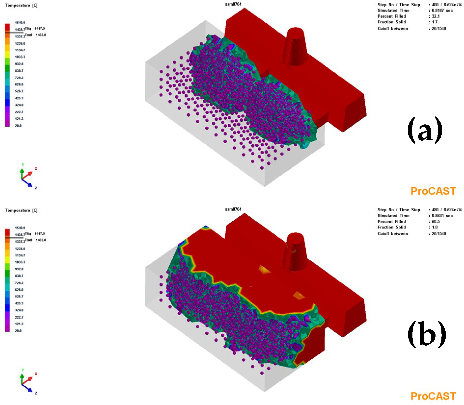
4.2. Filling Characteristics

The filling process of lost foam suspension casting is similar to that of lost foam casting. When no suspension agent is added, the casting filling time is 0.87 s, and when the addition amount of the suspension agent is 1%, the casting filling time is 0.95 s. Since the suspension agent almost does not melt during the filling process (as shown in Figure 4), the suspension agent plays a certain role in obstructing the flow of the liquid metal, so the time is longer.
After encountering high-temperature liquid metal, the foam decomposes and vaporizes, forming an air gap layer between the foam and the liquid metal. Researchers have used the cold quenching method, high-speed photography method and the electrode contact method to observe the flow patterns of different castings in lost foam casting [36,42]. For lost foam casting, the pyrolysis process of foam is the control link of the casting mold filling process and its essence is the reverse pressure resistance of pyrolysis gas to the liquid metal flow [43]. As a result, the filling process of the lost foam casting is different from that of ordinary sand casting. The liquid metal usually enters the casting cavity from the inner runner and fills forward in a radial arc, replacing the foam pattern layer by layer, and finally filling to the farthest part from the inner gate [44]. Under the parameters of this experiment, the thickness of the air gap layer is about 0.25 cm, and the gas pressure of the air gap layer is about 4.5 bar. During the filling process of the liquid metal, the foam stably advances until the filling is complete, as shown in Figure 5. It can be observed through the movement process of the air gap layer that the liquid metal filling is smooth and advances from the gate in a circular arc with decreasing curvature. The presence of the suspending agent hinders the liquid metal filling, but due to the uniform distribution of the suspending agent in the cavity of the casting, there is no obvious influence on the overall shape of the liquid metal filling. The filling process is smooth until the end, and there is no backflow caused by the impact of liquid metal casting, which can effectively avoid the uneven distribution of the suspending agent in the actual production process.
From the temperature field results of the overall observation of this model filling process, as shown in Figure 6, there is a color fluctuation of the flowing metal front, which indicates that the high-temperature liquid metal is pyrolyzing the foam material. Although the temperature of the liquid metal front of the filling process fluctuates, it has always had a high temperature and good fluidity, so that the foam pattern can be fully decomposed, no casting defects such as slag inclusion and wrinkled skin are produced and the casting can be smoothly formed. The filling time of the casting to 30% is 0.81 s. It takes 0.86 s for the filling to reach 60% and the filling ends at 0.95 s. The overall filling process is slow at first, then fast and then slow, which also conforms to the filling characteristics of the bottom pouring system [39,45]. The reason for the slow start is that at the beginning of pouring, the temperature of the liquid metal is high and the air volume is large at the moment of foam decomposition, but the exhaust capacity of dry sand is limited, resulting in an increase in the back pressure of gas accumulation at the front end of the filling mold, which further affects the filling mold. At the initial stage of filling, the high temperature liquid metal drops rapidly after encountering the suspension agent, which improves the excessive foam gas generated by the high temperature liquid metal to a certain extent and improves the filling ability of the liquid metal. However, after the temperature of the liquid metal is reduced, the viscosity will also have a certain increase, and the filling ability will be weak from this point of view. Therefore, the addition of the suspension agent did not change the phenomenon of slow filling in the early stage. In the subsequent filling stage, the chilling effect of the suspension agent, the gas generation of the foam and the exhaust effect of the dry sand gradually reached a balance. With the decrease of liquid metal temperature, the filling capacity was improved. The final stage of the filling time was longer because the liquid metal reached the place that needs to be filled far away and the heat was lost, making the filling ability weak. The results show that the filling flow was stable and spatter-free.
As shown in Figure 7, the Voids result shows that no foam material is in suspension surrounded by the liquid metal, the material is decomposed completely and can be discharged in time and there is no residual foam, so no defects such as slag inclusion and porosity will be formed.
The temperature curves of the filling and solidification process at the entrance of the inner gate (Point 1) and the farthest part of the casting from the gate, that is, the last part of the theoretical filling (Point 2), are respectively shown. The schematic diagram of the point location is shown in Figure 8, and the temperature curve is shown in Figure 9. Compared with the temperature curves of the two points, the liquid metal quickly rises to the highest temperature after filling to the position, goes through the rapid cooling stage, enters the latent heat release period and finally enters the stable cooling period. Point 1 is heated to the highest temperature by 0.14 s, and Point 2 is heated to the highest temperature by 0.05 s. Since Point 1 is at the lower side of the gate, high-temperature liquid metal will continue to enter the casting, a large number of bubbles will crack, burn and constantly absorb heat, resulting in temperature fluctuations at the liquid metal front and thus a relatively slow temperature rise. As for Point 2, the foam pattern has been completely replaced by liquid metal, the filling process ends, the front flow of liquid metal disappears and only the internal flow of liquid metal exists. Because of the local energy imbalance, the temperature fluctuation is small at this time and the temperature rises faster. In this experiment, due to the small size of the casting and the short filling time, the liquid metal flows from Point 1 to Point 2 very quickly after entering the cavity, so there is only a slight difference in the cooling curve.

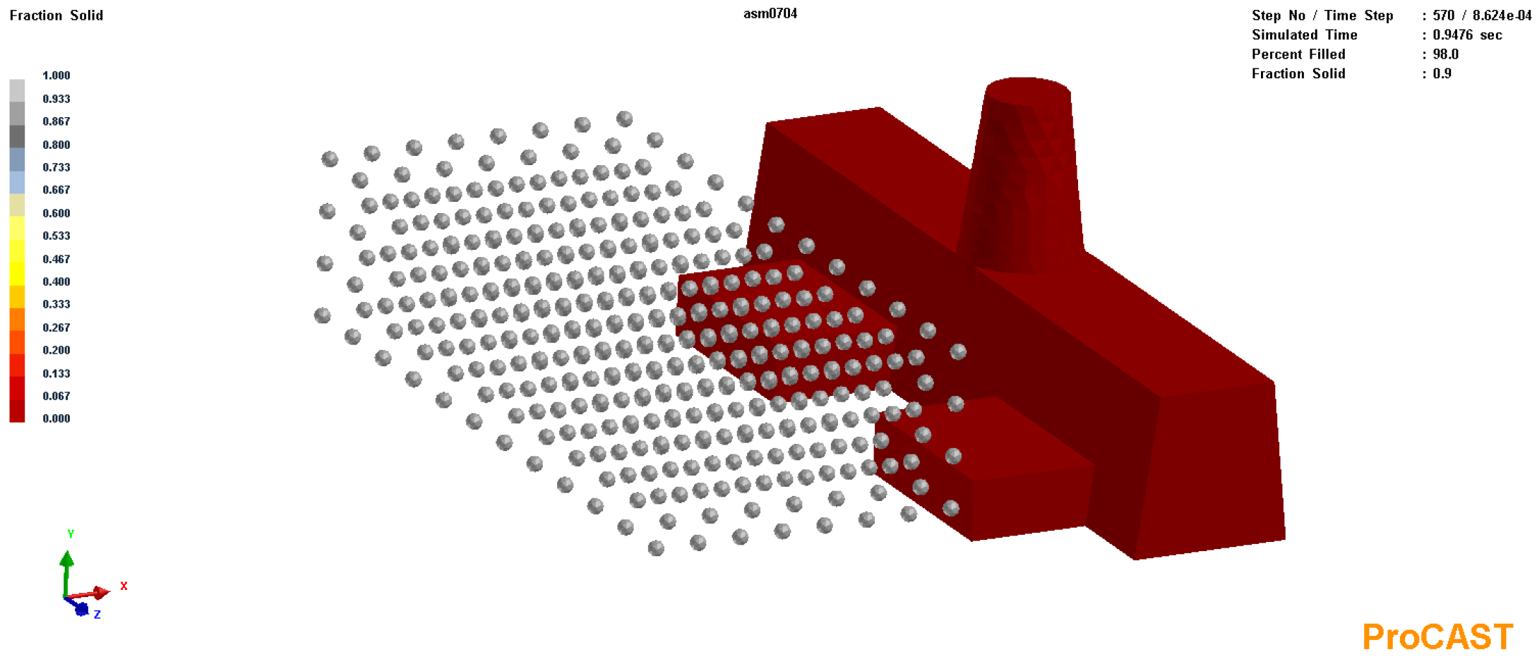
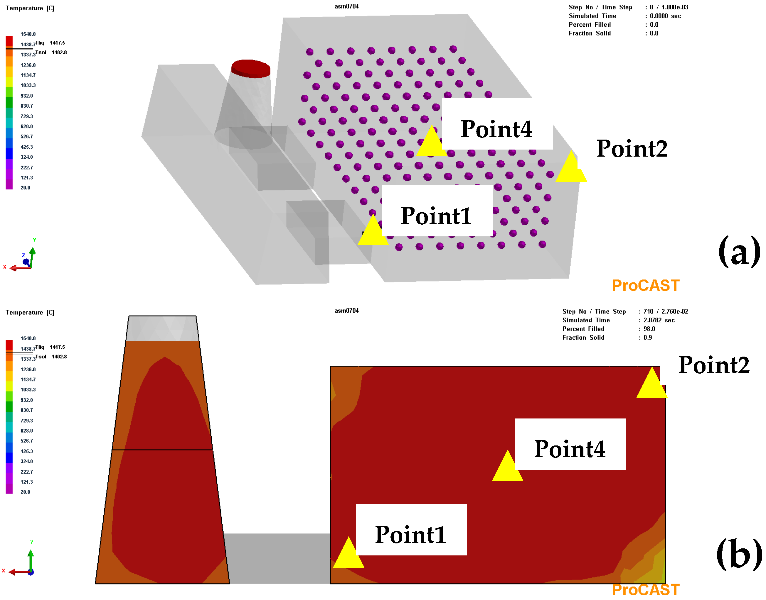
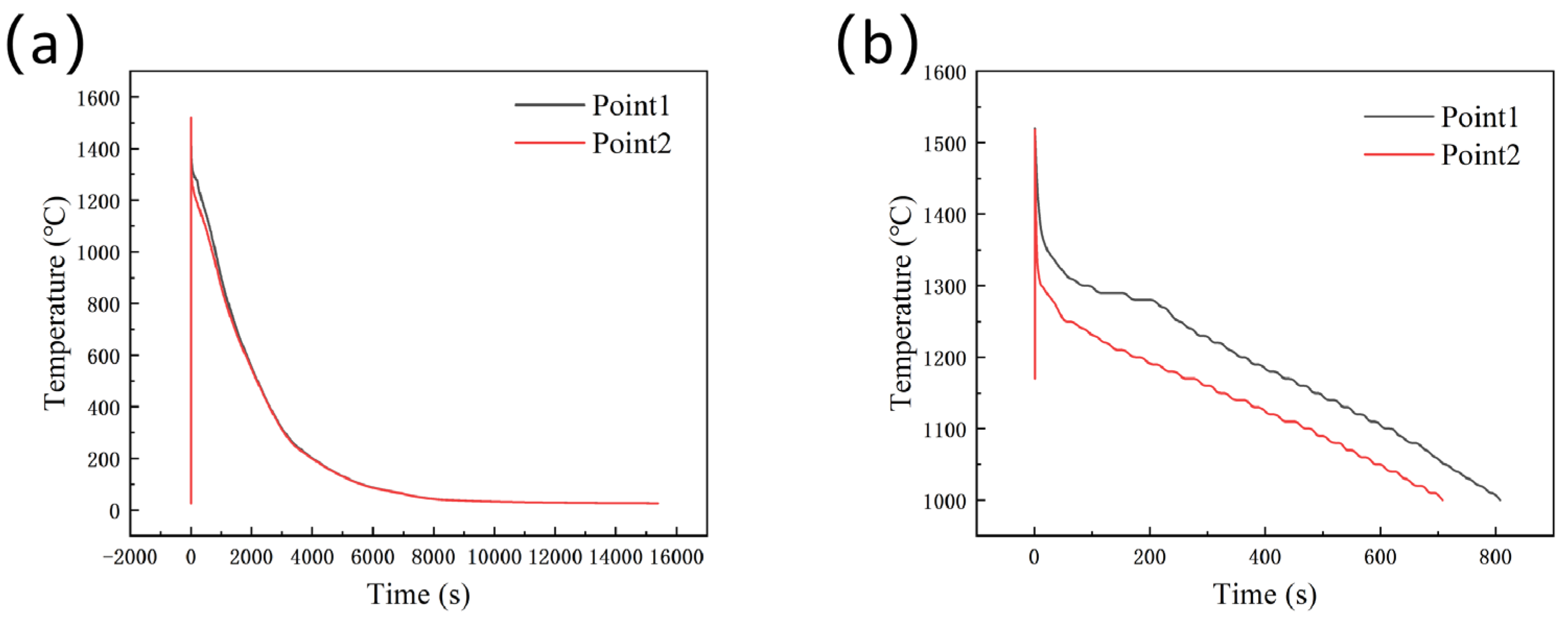
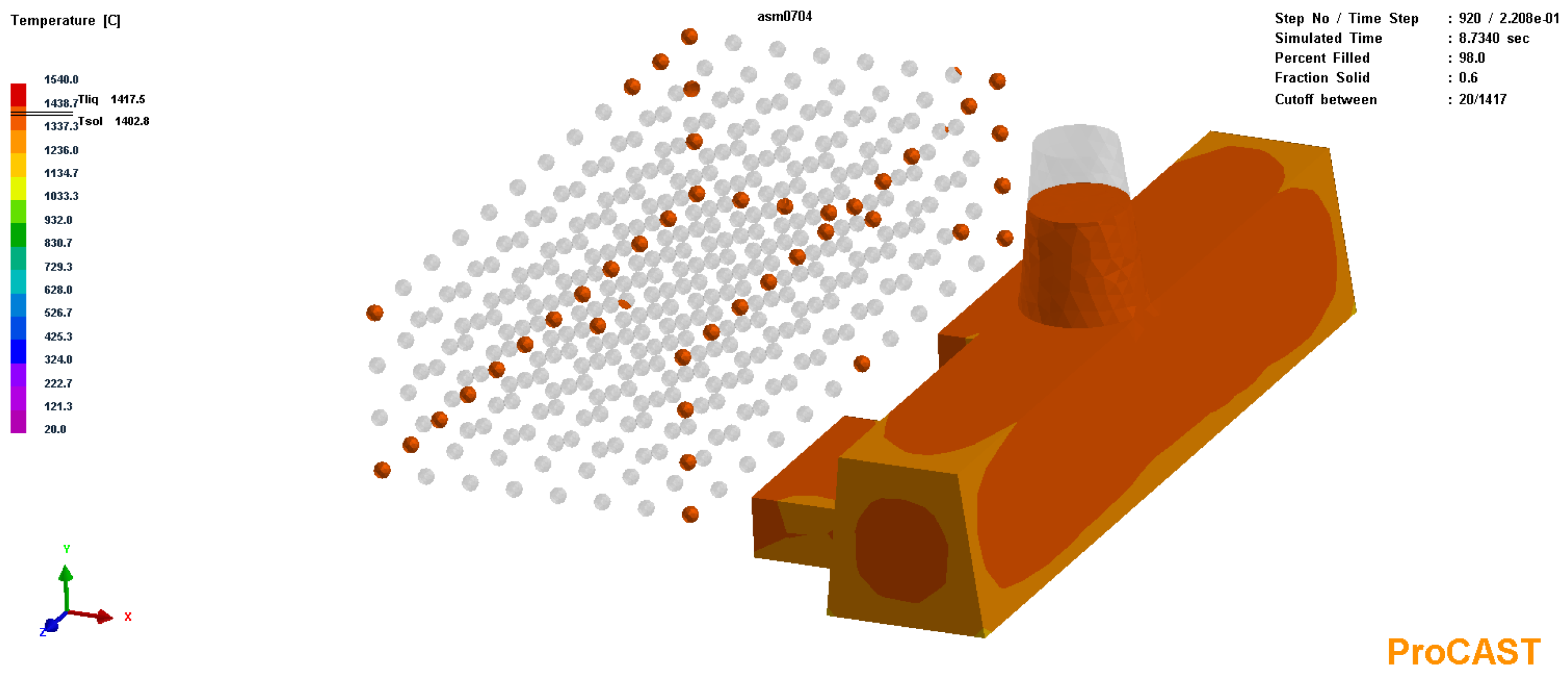
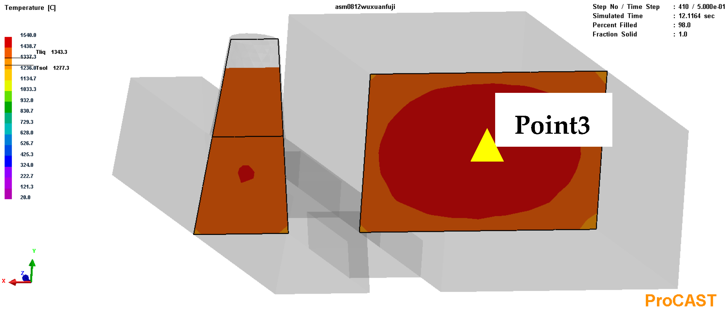
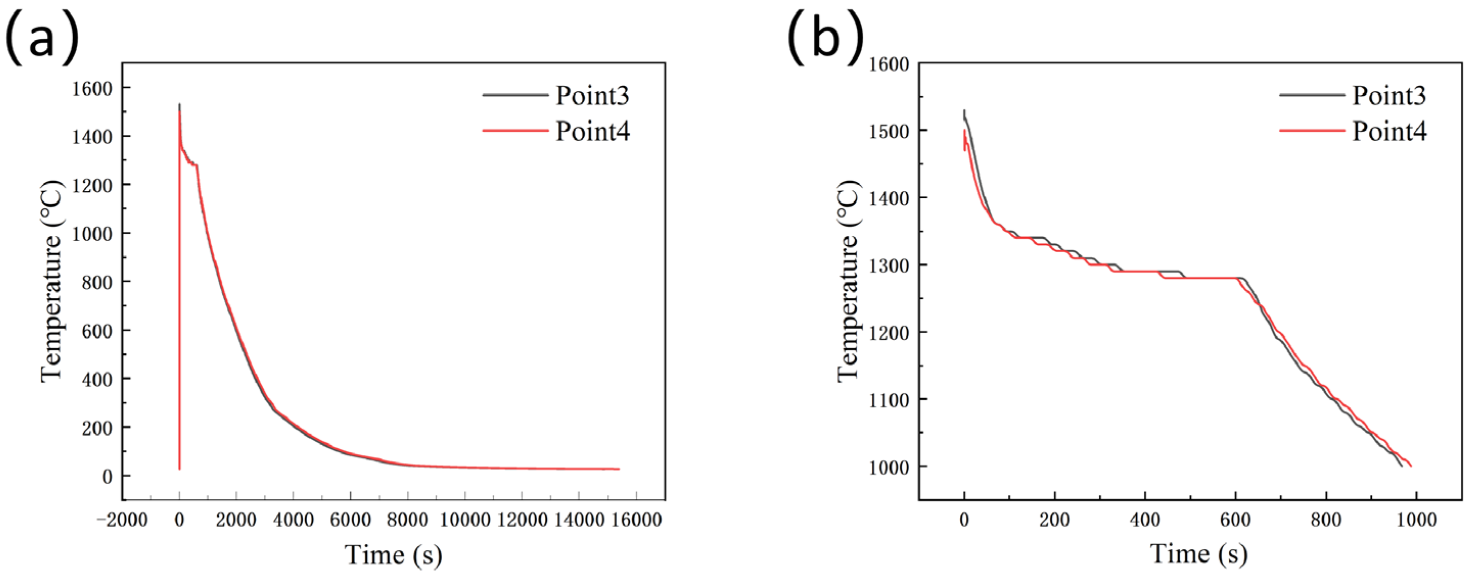
4.3. Solidification Characteristics

The suspension agent keeps heating up and melting in the solidification stage of the casting and most of the suspension agent usually melts in the actual production process of suspension casting. The Cut-off function was used to select the part whose temperature was lower than the liquidus temperature of TiFe (1417 °C), as shown in Figure 10. There were 388 metal spheres in the suspension, of which 41 were not completely melted. That is, 89.4% of the suspension was completely melted. It can be seen that the unmelted part was concentrated at the edge of the casting. Due to the long filling distance of the liquid metal and the short heating time of the suspension agent, the phenomenon of incomplete melting was caused. At the same time, the diameter of 2 mm was relatively large, and the suspension agent was not easy to melt to a certain extent.
By comparing the temperature field results of the model without the suspending agent and the model with 1% suspending agent, it was found that the chilling effect of the suspending agent exists but is not obvious. In this experiment, the geometric center position of the casting was selected as the temperature measurement point (Point 3 and Point 4) to compare the effect of the suspension agent. The location of the casting point (Point 3) without adding the suspension agent is shown in Figure 11 and the temperature curve at Point 3 and Point 4 is shown in Figure 12. It can be found from the temperature curve that the chilling effect of the suspension agent occurs within 0.44 s, the heat absorption time is very short and the maximum temperature drop is 50 °C. In addition, we studied the temperature field around the suspension agent. As shown in Figure 13, the suspension agent had an obvious heat exchange with the surrounding liquid metal during the heating and endothermic process, thus achieving the chilling effect. Zhi Xiaohui et al. [19] studied the microstructural refinement of a cast hypereutectic Fe20Cr4C alloy using a fluctuation method (suspension casting). With the treatment of 0.7% fluctuation, there is a maximum temperature drop of about 37 °C. This experimental result is in general agreement with the conclusion of the simulation. It is speculated that the cooling effect of the suspension agent is not obvious due to the large particle size, small distribution density and relatively insufficient addition amount. If the amount of suspension agent is increased, the temperature of the alloy can be further reduced, the solidification rate can be accelerated, the nucleation rate of the alloy can be increased and the growth of the primary carbide can be hindered. In addition, any powder that is not fully melted can serve as the heterogeneous nuclear point of the primary carbide, resulting in the refinement of the final carbide.

5. Conclusions

An innovative numerical simulation study on the lost foam suspension casting process of hypereutectic high-chromium cast iron was carried out. ProCAST software was used to observe the filling and solidification process of the simple cuboid ingot model, and the following important results were obtained.
(1) Through the simulation results of shrinkage porosity, it was found that the optimal process parameters within the study range were as follows: a negative pressure of 0.06 MPa, a pouring temperature of 1540 °C and 1% suspension agent.
(2) The addition of the suspension agent has an obstructive effect on the filling process of the lost foam casting, and the filling time is about 9% longer than that without the addition of the suspension agent.
(3) The pressure and thickness of the air gap layer remained stable during the process of filling with liquid metal. When the bottom casting system was adopted, the filling process was slow at first, then fast and then slow. The filling process was smooth and without turbulence or splashing phenomenon.
(4) The suspension agent melted during the solidification process. When the amount of TiFe was 1%, 89.4% of the suspension agent completely melted and the chilling effect of the suspension agent occurred within 0.44 s, resulting in a relative supercooling degree of about 50 °C for the liquid metal. It can be seen from the temperature curve that the solidification rate of hypereutectic high-chromium cast iron had increased under the lost foam suspension casting process. In order to further improve the chilling effect, it is necessary to increase the amount of suspension agent.

Author Contributions

Literature search, methodology, data collection and writing—original draft preparation, H.M.; writing—review and editing and project administration, H.F. All authors have read and agreed to the published version of the manuscript.

Funding

This research was funded by the National Natural Science Foundation of China, grant number 52075010.

Data Availability Statement

All data is contained within the article.

Conflicts of Interest

The authors declare no conflict of interest.

References

  1. Wang, X.H.; Jiao, Y.L. Effect of Ce Modification on Microstructure and Properties of Boron Containing Hypereutectic High Chromium Cast Iron. Foundry 2023, 72, 810–818. [Google Scholar]
  2. Jian, A.S.; Chang, H.W.; Ahmad, H.; Ma, X.D.; Zhang, M.X. Effect of solutes on the formation of primary carbides during solidification of hypereutectic high chromium cast irons through thermodynamic modeling. J. Mater. Sci. 2022, 57, 1429–1447. [Google Scholar] [CrossRef]
  3. Yilmaz, S.O.; Teker, T. Effect of TiBAl inoculation and heat treatment on microstructure and mechanical properties of hypereutectic high chromium white cast iron. J. Alloys Compd. 2016, 672, 324–331. [Google Scholar] [CrossRef]
  4. Zhou, X.K.; Wang, Y.; Wu, S.; Xiao, X.L. Effect of Nb Content on Microstructure and Mechanical Properties of Hypereutectic High Chromium Cast Iron. Hot Work. Technol. 2022, 51, 50–52. [Google Scholar]
  5. Li, P.; Yang, Y.H.; Shen, D.P.; Gong, M.Y.; Tian, C.; Tong, W.P. Mechanical behavior and microstructure of hypereutectic high chromium cast iron: The combined effects of tungsten, manganese and molybdenum additions. J. Mater. Res. Technol. 2020, 9, 5735–5748. [Google Scholar] [CrossRef]
  6. Jain, A.S.; Mustafa, M.I.; Sazili, M.I.I.M.; Chang, H.W.; Zhang, M.X. Effects of destabilization and tempering on microstructure and mechanical properties of a hypereutectic high-chromium cast iron. J. Mater. Sci. 2022, 57, 15581–15597. [Google Scholar] [CrossRef]
  7. Liu, Q.; Peter, H.; Zhang, H.W.; Wang, Q.; Pär, G.J.; Keiji, N. Effect of Heat Treatment on Microstructure and Mechanical Properties of Ti-alloyed Hypereutectic High Chromium Cast Iron. ISIJ Int. 2012, 52, 2288–2294. [Google Scholar] [CrossRef]
  8. Deng, J.X.; Cai, H.T.; Tian, Y.L. Study on Casting Process of Hypereutectic High Chromium Cast Iron. Foundry Eng. 2022, 46, 34–37. [Google Scholar]
  9. Zhang, K.; Zhang, J.P.; Zhang, Z.; Zhong, N.; Lu, S.W. Effect of Heat Treatment on Properties of Hypereutectic High Chromium Cast Iron. Foundry 2022, 71, 1133–1138. [Google Scholar]
  10. Zhang, K.; Zhang, J.P.; Zhong, N.; Lu, S.W. Effect of quenching and tempering process on microstructure and properties of Cr26 hypereutectic high chromium cast iron. Heat Treat. Met. 2022, 47, 156–163. [Google Scholar]
  11. Geng, B.Y.; Zhou, R.F.; Li, L.; Lv, H.Y.; Li, Y.K.; Bai, D.; Jiang, Y.H. Change in Primary (Cr, Fe)7C3 Carbides Induced by Electric Current Pulse Modification of Hypereutectic High Chromium Cast Iron Melt. Materials 2018, 12, 32. [Google Scholar] [CrossRef] [PubMed]
  12. Geng, B.Y.; Zhou, R.F.; Li, Y.K.; Jiang, Y.H. Effect of electric current pulse on size of primary carbides in hypereutectic high chromium cast irons in different solidification stages. Mater. Res. Express 2019, 6, 126551. [Google Scholar] [CrossRef]
  13. Gong, L.Q.; Fu, H.G.; Zhi, X.H. Corrosion Wear of Hypereutectic High Chromium Cast Iron: A Review. Metals 2023, 13, 308. [Google Scholar] [CrossRef]
  14. Wang, J.H. Suspension casting process. MW Met. Form. 1980, 05, 60–62. [Google Scholar]
  15. Fu, H.G.; Xie, P.M. Development and Application of Suspension Casting Process. Mod. Cast Iron 1966, 01, 33–34+46. [Google Scholar]
  16. Jiang, Z.W.; Luo, H.F.; Li, Z.J. The Effect of Suspension Casting on the Properties of Fly-Ash Particle Reinforced Al Matrix Composites. Adv. Mater. Res. 2012, 2044, 581–582. [Google Scholar] [CrossRef]
  17. Li, Q.S.; Liu, M.S. Effects of Suspension Casting on the Structure and Properties of High Chromium White Cast Iron. J. Taiyuan Univ. Sci. Technol. 2002, 23, 56–59. [Google Scholar]
  18. Dai, B.Y. Application of Suspension Casting to Firebrick Forming Dies of High-Chromium Cast Iron. Foundry 2009, 58, 726–728. [Google Scholar]
  19. Zhi, X.H.; Xing, J.D.; Fu, H.G.; Gao, Y.M. Effect of fluctuation, modification and surface chill on structure of 20%Cr hypereutectic white cast iron. Mater. Sci. Technol. 2009, 25, 56–60. [Google Scholar] [CrossRef]
  20. Yan, X.N. Present situation and development trend of lost foam casting technology. Sci. Technol. Ind. Parks 2017, 10, 120. [Google Scholar]
  21. Ma, G.B.; Tan, J.B.; Yu, Y.L.; Li, C.H. Study on Microstructure of Lost Foam Cast WCp/Fe Composites. Foundry 2020, 69, 149–153. [Google Scholar]
  22. Suyitno; Sutiyoko. Effect of Pouring Temperature and Casting Thickness on Fluidity, Porosity and Surface Roughness in Lost Foam Casting of Gray Cast Iron. Procedia Eng. 2012, 50, 88–94. [Google Scholar]
  23. Xie, M.G.; Zhu, C.G.; Zhou, J.X. Effect on Solidification Structure of Hypoeutectic Grey Cast Iron by Vacuum Condition in Lost Foam Casting. In Proceedings of the 2015 6th International Conference on Manufacturing Science and Engineering, Qingdao, China, 17–19 July 2015; pp. 1496–1500. [Google Scholar]
  24. Wu, G.H.; Luo, J.R.; Xie, M. Porosity of aluminum alloy in lost foam casting process. Trans. Nonferrous Met. Soc. China 2000, 10, 645–649. [Google Scholar]
  25. Li, M.X.; Guo, Q.W.; Chen, L.W.; Li, L.M.; Hou, H.; Zhao, Y.H. Microstructure and properties of graphene nanoplatelets reinforced AZ91D matrix composites prepared by electromagnetic stirring casting. J. Mater. Res. Technol. 2022, 21, 4138–4150. [Google Scholar] [CrossRef]
  26. Wang, J.; Pan, Z.X.; Wang, Y.F.; Wang, L.; Su, L.H.; Dominic, C.; Zhao, Y.H.; Li, H.J. Evolution of crystallographic orientation, precipitation, phase transformation and mechanical properties realized by enhancing deposition current for dual-wire arc additive manufactured Ni-rich NiTi alloy. Addit. Manuf. 2020, 34, 101240. [Google Scholar] [CrossRef]
  27. Liu, G.S.; Wang, W.C.; Zhang, Z.M.; Liu, J.H.; Li, Q.L. Effect of Suspension Casting on the Property of Low-Chromium White Cast Iron Produced by the EPC Process. Foundry 2001, 50, 666–669. [Google Scholar]
  28. Dai, H.Z.; Dai, H.M. Suspension Casting Process for Producing Wear Resistant High Manganese Steel. CN101880839A, 10 November 2010. [Google Scholar]
  29. Fu, H.G.; Wu, Z.W.; Li, E.; Lei, Y.P.; Lin, J.; Zhang, J.G. Method of Manufacturing Castings by Suspension Casting. CN104084541B, 13 April 2016. [Google Scholar]
  30. Edward, G.; Dariusz, K.; Andriy, B.; Andrzej, S. Evaluation of the Number of Primary Grains in Hypoeutectic Chromium Cast Iron with Different Wall Thickness Using the ProCAST Program. Materials 2023, 16, 3217. [Google Scholar]
  31. Albuquerque, C.E.S.; Silva, P.C.S.; Grassi, E.N.D.; Araujo, C.J.D.; Delgado, J.M.P.Q.; Lima, A.G.B. Optimizing the Gating System for Rapid Investment Casting of Shape Memory Alloys: Computational Numerical Analysis for Defect Minimization in a Simple-Cubic Cell Structure. Metals 2023, 13, 1138. [Google Scholar] [CrossRef]
  32. Yang, Q.; Zhu, X.T.; Wang, F.; Ma, D.X.; Wu, J.T. A Study of Sliver in C-Shaped Grain Selectors during Investment Casting of Single-Crystal Superalloy. Metals 2023, 13, 1102. [Google Scholar] [CrossRef]
  33. Gong, Y.N.; Malik, A.; Wang, Y.W.; Feng, S.J.; Zhao, D.H. Numerical Simulation and Experimental Studies of Gas Pressure Infiltration Al-356/SiC Composites. Metals 2022, 12, 2150. [Google Scholar] [CrossRef]
  34. He, T.Z.; Chen, Y.Y. Influence of Mold Design on Shrinkage Porosity of Ti-6Al-4V Alloy Ingots. Metals 2022, 12, 2122. [Google Scholar] [CrossRef]
  35. Yan, J.W. Estabishment of Foam Pattern Database and Research on Numerical Simulation of Lost Foam Casting. Master’s Thesis, Harbin University of Science and Technology, Harbin, China, 2014. [Google Scholar]
  36. Feng, B. Numerical Simulation of Mould Filling and Solidification of EPC For Aluminum Alloys Cylinder Head. Master’s Thesis, Hebei University of Science & Technology, Shijiazhuang, China, 2012. [Google Scholar]
  37. Wang, J.H. Suspension Casting; National Defense Industry Press: Beijing, China, 1982; p. 56. [Google Scholar]
  38. Huang, J.; Lin, Y.X.; Chen, W.P.; Qi, X.J. Numerical analysis of lost foam casting for large-caliber water meter shell. Adv. Mech. Eng. 2021, 13, 16878140211028059. [Google Scholar] [CrossRef]
  39. Zhao, Z.W.; Jia, L.M.; Yu, Y.L.; Li, C.H.; Zhao, H.S.; Tan, J.B. Process design and numerical simulation of lost foam casting for grey cast iron end caps. Hebei J. Ind. Sci. Technol. 2022, 39, 341–348. [Google Scholar]
  40. Hu, G.Q.; Peng, F.; Pan, F.Y.; Yang, Z.G.; Zhu, W.W. Influence of Negative Pressure Degree on Quality of Vacuum Negative Pressure Lost Foam Gray Iron Casting. Mod. Cast Iron 2018, 38, 33–37. [Google Scholar]
  41. Deng, C.; Long, J.; Zheng, Z.B.; Huang, Y.; Zheng, K.H. Numerical Simulation of Solidification Process in Lost Foam Casting of Caterpillar Board Based on ProCAST Software. Spec. Cast. Nonferrous Alloys 2021, 41, 368–371. [Google Scholar]
  42. Liang, H.; Li, Z.M.; Wang, Y.C.; Zahng, X.M.; Li, L.X.; Tan, J.B.; Xue, X.X. Filling Morphology of Gray Cast Iron Melt in Lost Foam Casting. Spec. Cast. Nonferrous Alloys 2007, 27, 870–871+818. [Google Scholar]
  43. Chang, Q.M.; Huang, N.Y.; Luo, J.R.; Ye, S.P. Numerical Simultion of Mold Filling in EPC Process. Foundry 1997, 2, 7–11. [Google Scholar]
  44. Li, F.J.; Zhao, H.; Ren, F.Z.; Song, S.B.; Shao, X.H. Simulations and experiments of mould filling in lost foam casting. Int. J. Cast Met. Res. 2020, 33, 194–200. [Google Scholar] [CrossRef]
  45. Dai, G.H. Application of Lost Foam Casting Process for Ductile Iron Shell Based on ProCAST. Master’s Thesis, Anhui University of Technology, Maanshan, China, 2018. [Google Scholar]
Figure 1. Casting mesh division model.
Metals 13 01761 g001
Figure 2. Casting and suspension mesh transition diagram.
Metals 13 01761 g002
Figure 3. Effect of negative pressure on shrinkage porosity of castings: (a) negative pressure is 0.04 MPa; (b) negative pressure is 0.06 MPa.
Metals 13 01761 g003
Figure 4. Results of solid phase ratio of suspension agent at the end of filling stage.
Metals 13 01761 g004
Figure 5. Advancing process of air gap layer during mold filling: (a) mold filling to 35%; (b) mold filling to 50%; (c) mold filling to 70%.
Metals 13 01761 g005
Figure 6. Temperature field results of filling process: (a) mold filling to 30%; (b) mold filling to 60%.
Metals 13 01761 g006
Figure 7. Voids result in the mold-filling process.
Metals 13 01761 g007
Figure 8. Schematic diagrams of the points taken at the entrance of the inner gate (Point 1), at the furthest point of the casting from the inner gate (Point 2) and at the center of the casting (Point 4): (a) three-dimensional schematic diagram of the location of the points taken; (b) schematic diagram of the location of the points taken in the XY-plane.
Metals 13 01761 g008
Figure 9. Temperature profiles at the entrance of the inner gate (Point 1) and at the furthest point of the casting from the inner gate (Point 2): (a) overall temperature results; (b) temperature profiles near high-temperature range.
Metals 13 01761 g009
Figure 10. Unmelted part of the suspension agent.
Metals 13 01761 g010
Figure 11. Schematic diagram of point taken of castings without adding suspension agent.
Metals 13 01761 g011
Figure 12. Temperature profiles of model without suspension and with 1% suspension agent added: (a) overall temperature results; (b) temperature profiles near high-temperature range.
Metals 13 01761 g012
Figure 13. Temperature field near the suspension agent (Typical chilling effect can be observed in the white frame).
Metals 13 01761 g013
Table 1. Chemical composition of hypereutectic high-chromium cast iron (mass fraction, wt%).
CCrMoMnSiFe
43510.60.8Bal.
Disclaimer/Publisher’s Note: The statements, opinions and data contained in all publications are solely those of the individual author(s) and contributor(s) and not of MDPI and/or the editor(s). MDPI and/or the editor(s) disclaim responsibility for any injury to people or property resulting from any ideas, methods, instructions or products referred to in the content.

