Article

Anisotropic Tensile and Compressive Strengths of Al–4 wt.%Cu Alloy Powder: Part 1—Effects of Compaction Loads and Heat Treatments

by
Rodrigo S. Bonatti
1,
Ausdinir D. Bortolozo
1,2,
Rodrigo F. G. Baldo
2,
Erik Poloni
3 and
Wislei R. Osório
1,2,*
1
School of Technology, Universidade Estadual de Campinas (UNICAMP), Limeira 13484-332, SP, Brazil
2
Research Group in Manufacturing Advanced Materials, School of Applied Sciences, Universidade Estadual de Campinas (UNICAMP), Limeira 13484-350, SP, Brazil
3
Centre for Advanced Structural Ceramics, Department of Materials, Imperial College London, London SW7 2ZA, UK
*
Author to whom correspondence should be addressed.
Metals 2023, 13(10), 1710; https://doi.org/10.3390/met13101710
Submission received: 23 August 2023 / Revised: 26 September 2023 / Accepted: 2 October 2023 / Published: 7 October 2023
(This article belongs to the Special Issue Microstructure and Characterization of Metal Matrix Composites)

Abstract

:
Powder metallurgy stands out as a preferred manufacturing method across various industries due to its advantages in design flexibility, material efficiency, and cost-effective production. In this work, we study the influence of different compaction directions on the strength characteristics of parts produced using powder metallurgy. Al–4 wt.%Cu alloys are used due to their recyclability. We use three distinctive compaction pressures. After sintering, samples are either air-cooled or water-quenched and naturally aged (T4 temper). Both the compressive and tensile strengths are characterized and thoroughly analyzed. This research highlights the significant impact of both heat treatments and compaction directions on anisotropic strengths. The novelty of this research lies in the use of powders that can be reclaimed from machining, turning, or foundry rejections. By eliminating or minimizing the melting stage and employing powder metallurgy, we achieve cost-effective and environmentally friendly processes. Furthermore, we underscore the critical role played by careful planning of compaction loads, compaction directions, and heat treatments in determining the final mechanical performance. This approach is not only economically viable but also aligns with the growing adoption of environmental, social, and governance (ESG) practices in industry.

1. Introduction

In powder metallurgy, compaction is an essential step performed before sintering a green body. It is crucial to accurately determine the compaction loads and density distributions in the final product, and the parameters required for this process depend on the desired or planned application. Factors such as particle size and shape, mechanical features, and particle surface properties significantly influence the resulting preform [1].
Furthermore, the geometry and surface characteristics of the tools used in compaction, along with the control of applied loads, play a vital role in determining the final soundness and properties of the product [2]. Some models [3,4,5,6] have been proposed to explain the compaction behavior of powders, but accurately predicting the mechanical properties remains challenging. Previous studies have shown that the strength of a compact depends on the compaction mode employed [5,6,7]. Generally, the tensile strength perpendicular to the compaction direction is higher than that along the compaction direction.
Extensive literature, including studies on strength anisotropy in distinct materials during cold compaction, pressing, and after sintering, has been reviewed [7]. The results show that both ductile and brittle powders exhibit strength anisotropy, which is influenced by density. In the case of ductile powders, the highest strength was observed in the transverse direction due to crack deflection resulting from increased particle overlap and flattening. For brittle powders, it was proposed that particle fragmentation along the compaction direction weakens the strength in the transverse direction [7]. Previous work also presented models that successfully explain the mechanisms related to strength anisotropy [2,8,9]. Loidlt et al. [2] have used a model based on the multi-particle finite element method [2] to predict the anisotropic elastic and plastic properties. Cao et al. [8] have reported the anisotropy in tensile mechanical properties of bulk Al samples fabricated by spark plasma sintering. Xu et al. [9] have investigated the anisotropic mechanical behavior of phyllite material. However, the effects of heat treatments on the microstructure of Al-alloys-compacted powders have not been thoroughly investigated in the past. Although different heat treatments are widely employed in industry, and significant improvements in the properties of 2xxx (Al–Cu) casting alloys and composites have been reported [10,11,12,13,14,15], there is a clear lack of systematic studies supporting these findings.
In this work, we used Al–Cu alloy powders to investigate the impact of compaction pressure, strength anisotropy, and heat treatment on the microstructure and mechanical properties of sintered samples. First, compacted samples were produced in the transverse and longitudinal directions at different pressures within 1 h after obtaining alloy powders. Next, the samples were densified using previously optimized sintering parameters [16,17,18,19]. In the final stage of the sintering cycle, the samples were either air-cooled or subjected to water quenching, followed by natural aging. Finally, both the compressive and tensile strengths were characterized. A particular contribution of this work lies in the use of Al–4 wt.%Cu (Al–4Cu) alloys, which can be recycled from conventional machining, drilling, and turning processes, or taken from rejection volumes in foundries [16,17,18,19,20]. The recyclability of these alloys helps reduce the overall costs associated with conventional processing routes based on atomization and electrolytic methods. While the use of ball milling to adjust particle size distribution still impacts the use of recycled powders, this work represents a step forward in developing processing routes that address the need for both environmental friendliness and cost-effectiveness in alloy production. As environmental, social, and governance (ESG) considerations have gained increased significance among investors, consumers, and stakeholders, scientific research is expected to play a key role in enabling new practices within industries [21]. Although it is recognized that aluminum oxidates instantly and that its complete sintering is difficult to achieve, the novelty and contribution of these investigations concern better understanding compacts which have been sintered and treated in a short period of time (~1 h). This process also allows the use of powders or particles from machining, showing that the process is feasible within certain limitations and specific conditions.

2. Materials and Methods

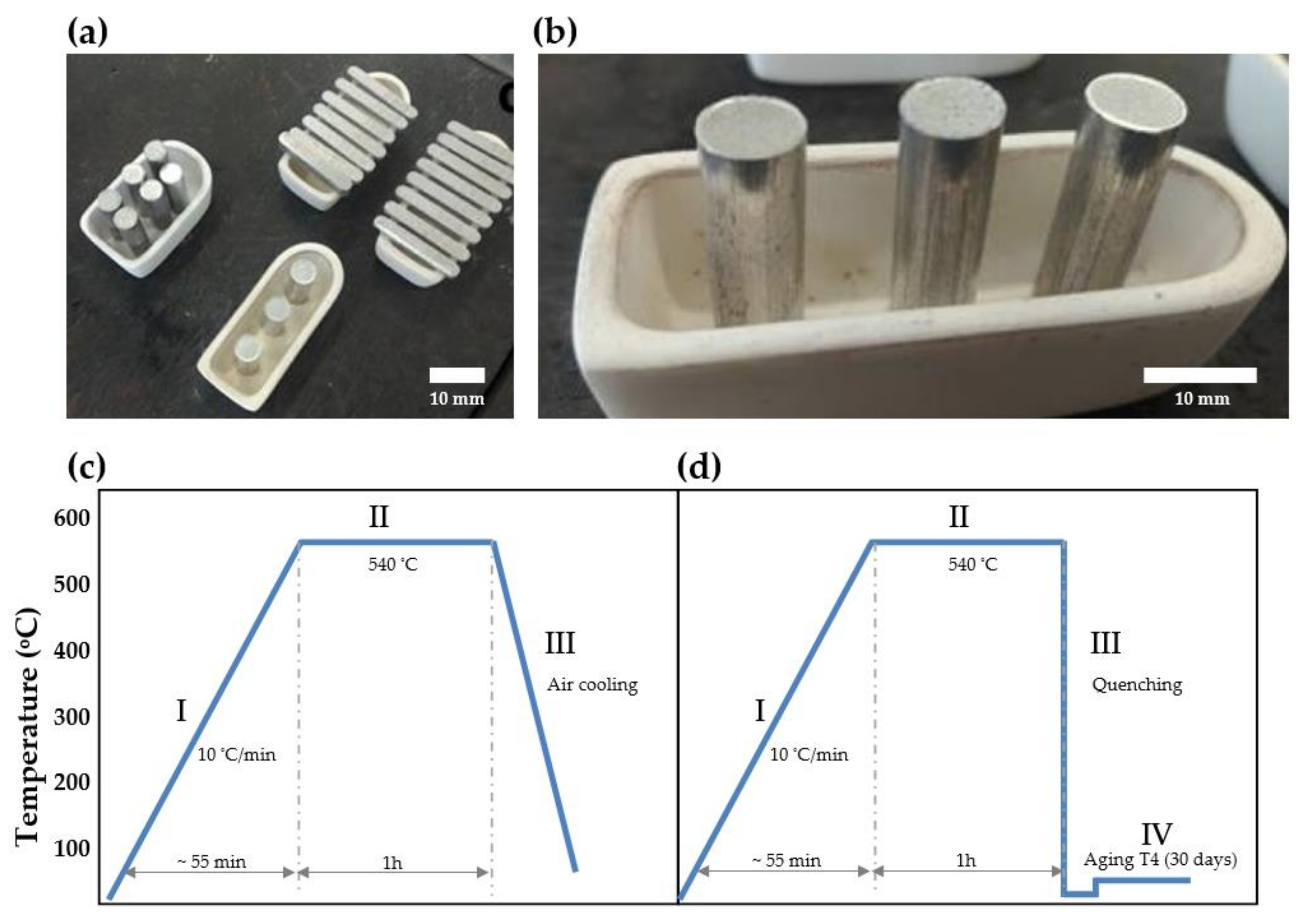
2.1. Initial Materials, Powder Production, and Compaction

This work aims to study the casting of alloys from rejection volumes in foundries. To this end, the chosen processing route involves producing an Al–4Cu alloy using conventional techniques, drilling it to create an alloy powder, and casting recycled alloys using powder metallurgy. This alloy composition was selected due to its importance for aerospace and automotive applications [10,15,16,17,18].
First, as-cast ingots of an Al–4Cu alloy were produced using commercial Al (99.8 wt.% Al, Alux and Albras, Nova Odessa and Barcarena, Brazil) and electrolytic Cu (99.89 wt.% Cu). The Al contained 0.11 wt.% Fe, 0.06 wt.% Zn, 0.02 wt.% Mn, and less than 0.009 wt.% Cu, with other impurity levels below 0.001 wt.%. The alloy was poured into a permanent steel mold (low-carbon, SAE 10145) under flowing argon (~2 L/min) and cast using directional solidification. Cylindrical ingots with a diameter of 50 mm were produced.
Next, an alloy powder consisting of flake-shaped particles was obtained by drilling the as-cast ingots. To prevent the presence of oxides from the casting in the drilled powder, the surfaces of the ingots were initially ground, and the oxide films were removed. The obtained powder was immediately compacted into new ingots. It is important to note that we did not use sieves, which eliminates the need for time-consuming sieving stages. Previous studies have shown that this approach offers a favorable balance between sieving time, particle morphology, and achieved densification level [18,19,20].
Finally, the produced powders were compacted using a hydraulic press and two different tempered dies made out of VC-131 steel with a hardness of 60 HRC (Figure 1a,c). Transverse specimens, measuring 32 mm × 5 mm × 2 mm, were produced by applying the compaction load in a direction perpendicular to that of the mechanical characterization (red arrows, Figure 1b). Cylindrical specimens, with dimensions of ϕ6 × 35 mm, were produced using a double-action compaction die (Figure 1c) by compacting along the specimen’s symmetry axis (Figure 1d). To characterize the compressive strength of transverse samples, we used sections from the sample depicted in Figure 1b and applied compressive pressures (blue arrows) perpendicular to the compaction direction (red arrows). When subjecting cylindrical specimens to a transverse load (Figure 1d), we employed the Brazilian indirect tensile test. Transverse and longitudinal specimens were produced using 1 and 3 g of the Al–4Cu alloy powder, respectively. We applied compaction pressures of 300, 400, and 600 MPa to all specimens, and the experimental procedure was repeated in triplicate to ensure the reproducibility of the results. The use of different shapes (transversal and longitudinal) did not lead to deleterious effects in the experimental results. A more detailed discussion on this matter is provided in Section 3.3.2.

2.2. Densification Measurements and Heat Treatments

The theoretical density ( ρ t ) and the densification (D) of both the green and sintered samples were calculated according to the following equations:
1 / ρ t = C A m / ρ A + C B m / ρ B
D = ρ / ρ t ,
where A and B are the phases of the samples; C A m and C B m are their mass fractions; ρ A and ρ B are their densities; and ρ is the apparent density, obtained experimentally using Archimedes’ principle (ASTM B962-17). The expected theoretical density of the alloys can be calculated with Equation (1) by using pure Al and Cu in the binary mixture. This yields a value of 2.778 g/cm3, which is a simplification from the metallurgical point of view. Alternatively, the theoretical density can be calculated using the Scheil equation for non-equilibrium solidification, which indicates that 92.16 wt.% of Al–4Cu alloys comprises Al-rich phases, and 7.84 wt.% comprises the eutectic phase [22]. Of the eutectic fraction, 50% is constituted by Al lamellae and the other 50% by Cu. This results in a density of 2.776 g/cm3, which is substantially close to the first estimate using pure Al and Cu.
The green samples were placed in alumina crucibles (Figure 2a) and sintered in a muffle-type furnace under flowing argon (~5 L/min). The sintering cycle adopted in this work consisted of heating at approximately 10 °C/min and holding at 540 °C for 1 h. These parameters were selected based on economic considerations and previous results [10,11,12,16,17,18,19]. Notably, the selected sintering temperature was intentionally kept below the eutectic temperature of the used alloy (548 °C) to prevent the formation of liquid phases.
Based on the cooling step after sintering, two different groups of compacted Al–4Cu samples were prepared: the first group of samples was air-cooled, a process similar to annealing; the second group was water-quenched at 27 ± 2 °C immediately after sintering and naturally aged for 30 days, which corresponds to a typical T4 treatment [10,11,12,16,19,23,24,25,26]. Triplicate samples were used for each group to ensure the reproducibility of our results. Figure 2c,d provides a schematic representation of the sintering process and heat treatments used for both groups.

2.3. Mechanical Properties and Microstructural Characterization

To determine the resulting mechanical properties of the sintered and compacted samples, tensile and compressive tests were conducted following the Metal Powder Industries Federation (MPIF) standards #10 and #41, which are similar to ASTM E8M/E9M. For the tensile test of transversal and longitudinal samples, gauge lengths of 15 (±0.1) mm and 30 (±0.1) mm were used, respectively. The tests were performed at a crosshead speed of 0.25 mm/min, which corresponds to a strain rate of approximately 2 × 10⁻⁴ s−1 at a temperature of 24 (±2) °C. The tests were conducted using an electrohydraulic servo machine (Equilam® WDW-100E, Time Group Inc., Beijing, China).
A scanning electron microscope (SEM) (VEGA3, TESCAN, Brno, Czech Republic) was used to characterize the microstructure of alloy powders and the recycled alloy samples. Crystallographic analyses were conducted with an X-ray diffractometer (X’Pert PANalytical®, Malvern, UK) using Cu- radiation with a wavelength of 0.15406 nm and operated at 40 kV and a 30 mA.

3. Results and Discussion

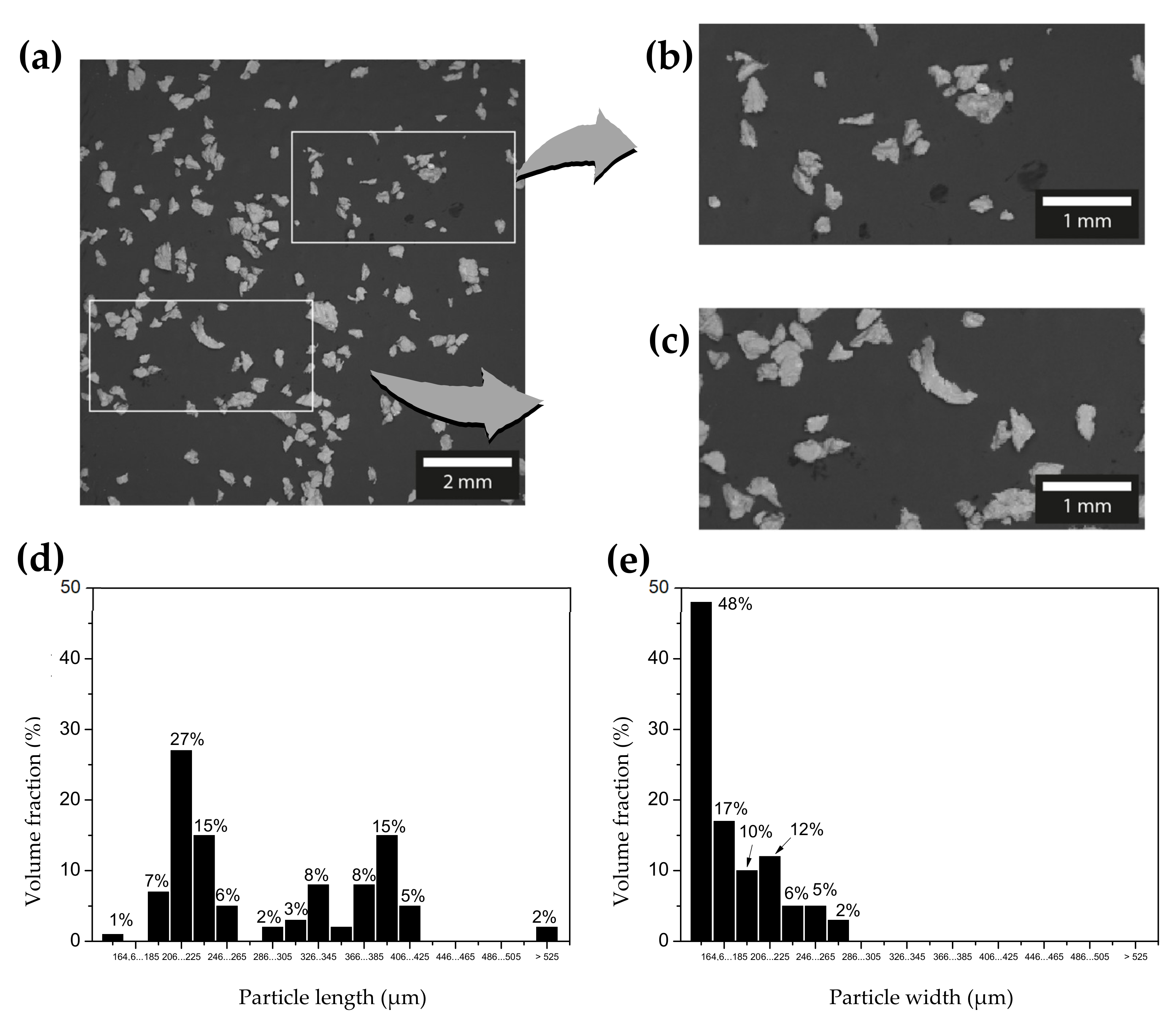
3.1. Alloy Powders and Anisotropic Effect on Densification

Typical SEM images of the particles in the alloy powder are shown in Figure 3a–c. The particles are affixed to conductive carbon adhesive tape, and both their length and width are measured. The obtained powder exhibits reasonably ductile characteristics. As a result, some particles appear more spheroidal, while the majority tend to have a flattened shape. This is a result of the drilling process, as previously reported [16,18,19].
The distributions of particle sizes with respect to length and width show noticeable distinctions. The flattened morphology is characterized by a length that is roughly twice the width, with average values of 290 μm and 160 μm, respectively. A bimodal distribution in the lengths of particles is also observed, which has also been observed by Satizabal et al. [16] and Bonatti et al. [18] when compacting ductile particles.
Figure 4a,c shows the densification of transverse and longitudinal Al–4Cu alloy samples, respectively, as a function of the compaction pressure. In both cases, the densification is plotted for green and sintered samples. Different equations can be used as a means to analyze the compressibility of the powders [20,27,28]. In this work, the influence of compaction pressure on the densification is described according to the following equation, reported by Fogagnolo et al. [20]:
ln 1 / 1 D = A P 0.5 + B ,
where P is the compaction pressure; A is a coefficient related to the plastic deformation of particles; and B is a proportionality constant. When ln 1 / 1 D is plotted against P 0.5 , A and B are directly obtained from the linear curves. The curves in Figure 4b,d were fitted to the experimental data shown in Figure 4a,c, respectively, using Equation (3). This fitting resulted in coefficients of determination higher than 0.94.
A comparison of different steps of the processing route evidences that the slopes of the green samples (0.047 and 0.043) are around three times higher than those of the sintered samples (0.0157 and 0.0156). This suggests distinct deformation capacities, favoring the green samples, as expected. Values of 0.0157 and 0.0156 were obtained for the parameter A when comparing transverse and longitudinal sintered samples, respectively. This indicates that both samples have similar deformation capacity behavior for the applied pressures, which can be attributed to their comparable particle size, chemical composition, and morphology. The obtained values for the parameter B of transverse and longitudinal samples were 2.06 and 1.88, respectively. While this ~10% difference could indicate a possible impact of the initial compaction volumes (see Section 2), it can be interpreted as a technical tie, considering the error ranges of the experimental values.
The SEM micrograph in Figure 4e shows the porosity level observed in a transversal sample compacted at 600 MPa and subsequently sintered. Although it is not common to use a micrograph to determine the densification level, it can help illustrate the relationship between mechanical behavior and densification, as will be discussed further. In a previous investigation [29], SEM images were used with threshold images technique (ImageJ® software, version 1.53t, Bethesda, MD, USA) to determine the porosity level. The results showed a good similarity with the densification levels determined using Archimedes’ method.
Regarding the densification level of sintered samples, the transverse ones exhibit the highest average relative densities. Because density has a huge impact on the mechanical properties of aluminum alloys, its maximization is of great importance. The values obtained for transverse and longitudinal samples were 90% and 87%, respectively. This suggests that the compaction direction plays an important role in the resulting densification and mechanical behavior of the Al–4Cu alloy produced via powder metallurgy.
Fogagnolo et al. [20] observed distinct sliding and cold-welding behavior during the compaction of spheroidal and flattened particles. When an asymmetrical-opposed force is applied, particularly with flattened particles, sliding and cold-welding occur at the contact points between them. On the other hand, when more spheroidal particles are compacted, mainly symmetrical-opposed forces prevail, and no sliding and cold-welding occur. Fogagnolo et al. [20] also found that spheroidal particles have a lower parameter, A , indicating lower deformation capacity compared to flattened particles. Additionally, previous studies have indicated that spheroidal particles exhibit greater variation in accumulated energy compared to flattened particles, as compaction leads to a decrease in volume energy and an increase in surface energy [7,18,19]. Therefore, flattened particles have a lower energy recovery since their initial energy accumulation during compaction is lower [17,18,19]. This results in better energy dissipation due to the randomness in filling the matrix. Consequently, the surface areas of interaction between particles impact energy recovery. Spheroidal particles mainly interact at the tangent points, while flattened particles interact over a larger contact area, leading to higher densification [6,7]. Some reports have highlighted that the compaction of fine particles in acicular or needle-shape powders yields better compaction than that of spheroidal particles [16,17,28,29,30,31]. In this investigation, a similar morphology and particle size distribution is adopted, as shown in Figure 3. It is important to note that our main objective is to study the impact of different compaction directions while keeping the compaction pressures constant. In the next section, the anisotropic effects on the resulting tensile and compressive strengths will be evaluated.

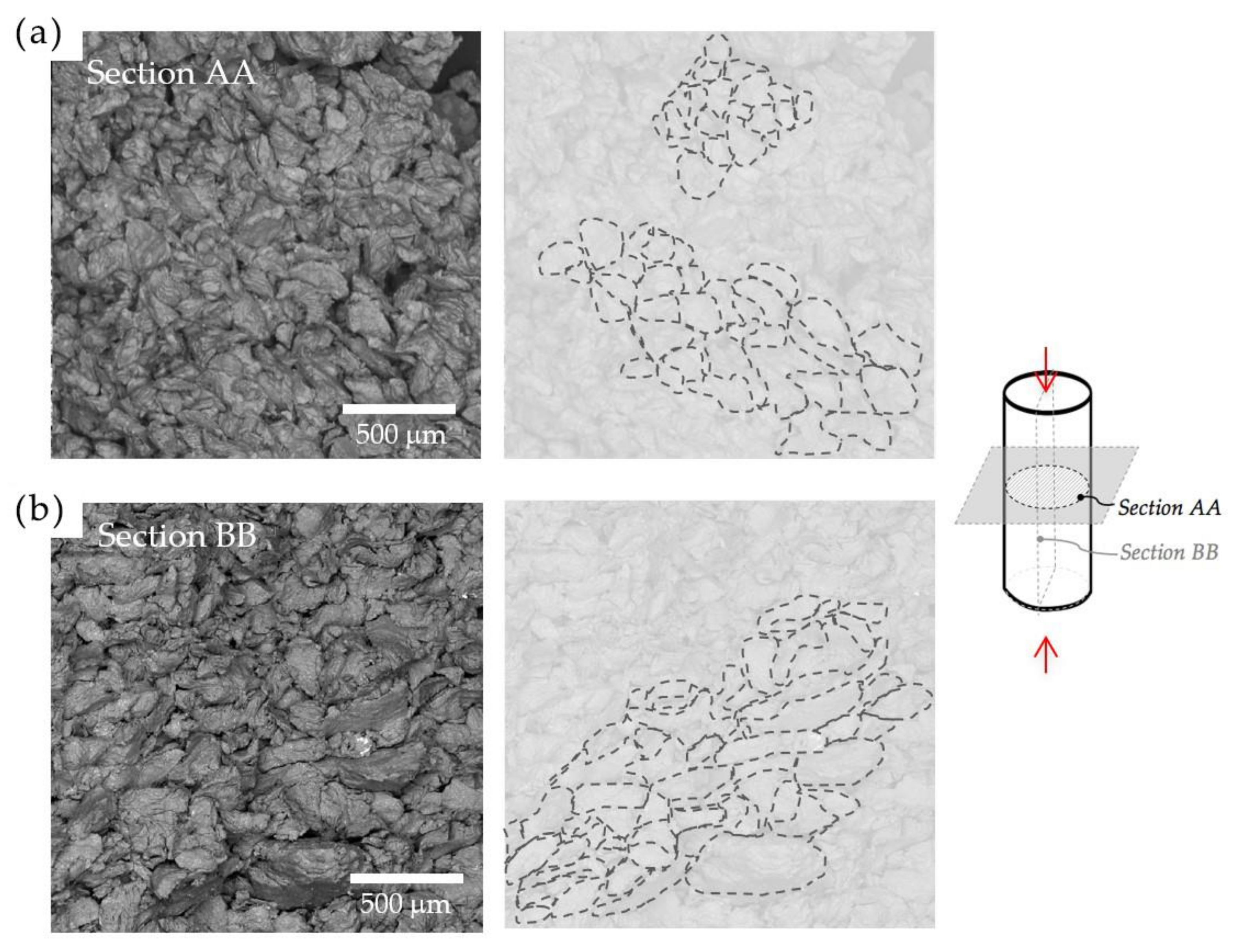
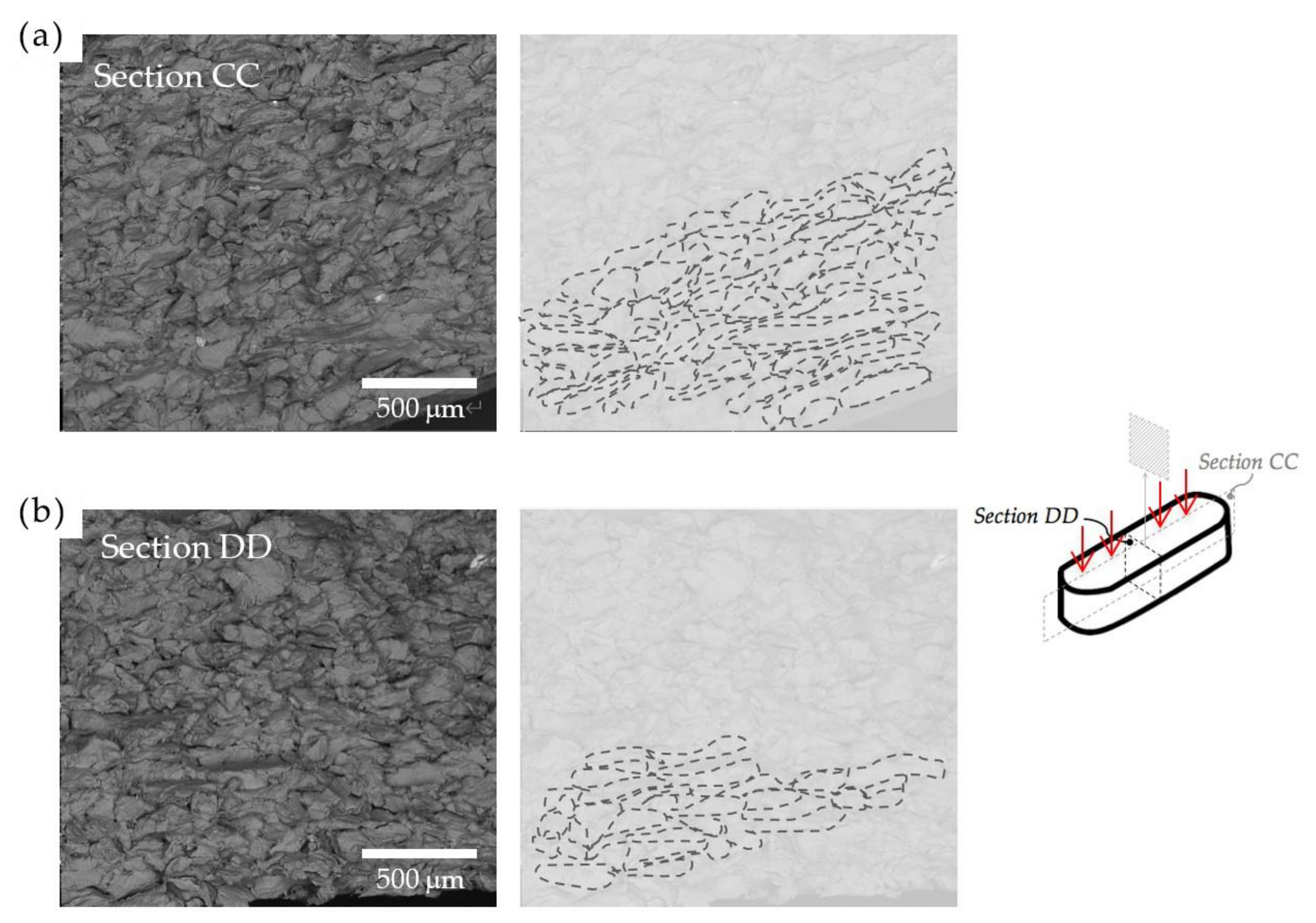
3.2. Anisotropic Effect on Morphology of Compacted Particles

Figure 5 and Figure 6 show the morphology of the compacted samples after sintering. They were taken from fracture surfaces and evidence no significant difference in morphology between air-cooled and water-quenched samples.
Figure 5a displays a typical SEM image of the fracture surface of a longitudinal sample across section AA. The sample was compacted in a direction perpendicular to section AA, and the compacted particles in it appear to be relatively spheroidal, as evidenced by the ghost lines. The morphology of section BB, shown in Figure 5b, evidences the presence of flattened particles when compared to the ones in section AA. Similarly, Figure 6a,b depicts the morphologies obtained after the compaction of transverse samples. Images from the sections CC and DD, both parallel to the applied pressure, evidence the predominance of flattened particles.
When correlating the morphologies shown in Figure 5 and Figure 6 with the compressibility results in Figure 4, it is observed that the different compaction directions lead to different morphologies. Although both longitudinal and transverse samples show very similar plastic deformation capacities, represented by the slope shown in Figure 4, a flattened morphology was observed in the transverse samples, implying an anisotropic effect on the examined compacted samples. These observations are consistent with the statements provided by Fogagnolo et al. [20] in their investigation of Al powder alloys.
Galen and Zavaliangos [7] have found distinctive anisotropic strengths when comparing ductile and brittle powders. They concluded that for ductile powders, higher strength results are observed in the transverse direction due to increased crack deflection resulting from higher particle overlap compared to the longitudinal direction. Conversely, for brittle powders, particle fragmentation occurring along the compaction direction weakens the strength in the transverse direction. In both cases, strength anisotropy is influenced by density, with ductile materials becoming anisotropic and brittle materials becoming isotropic as density increases. Based on these findings, the next sections relate the mechanical strength of our recycled alloys with respect to their morphology and compaction direction, and the used heat treatment.

3.3. Anisotropic and Mechanical Properties

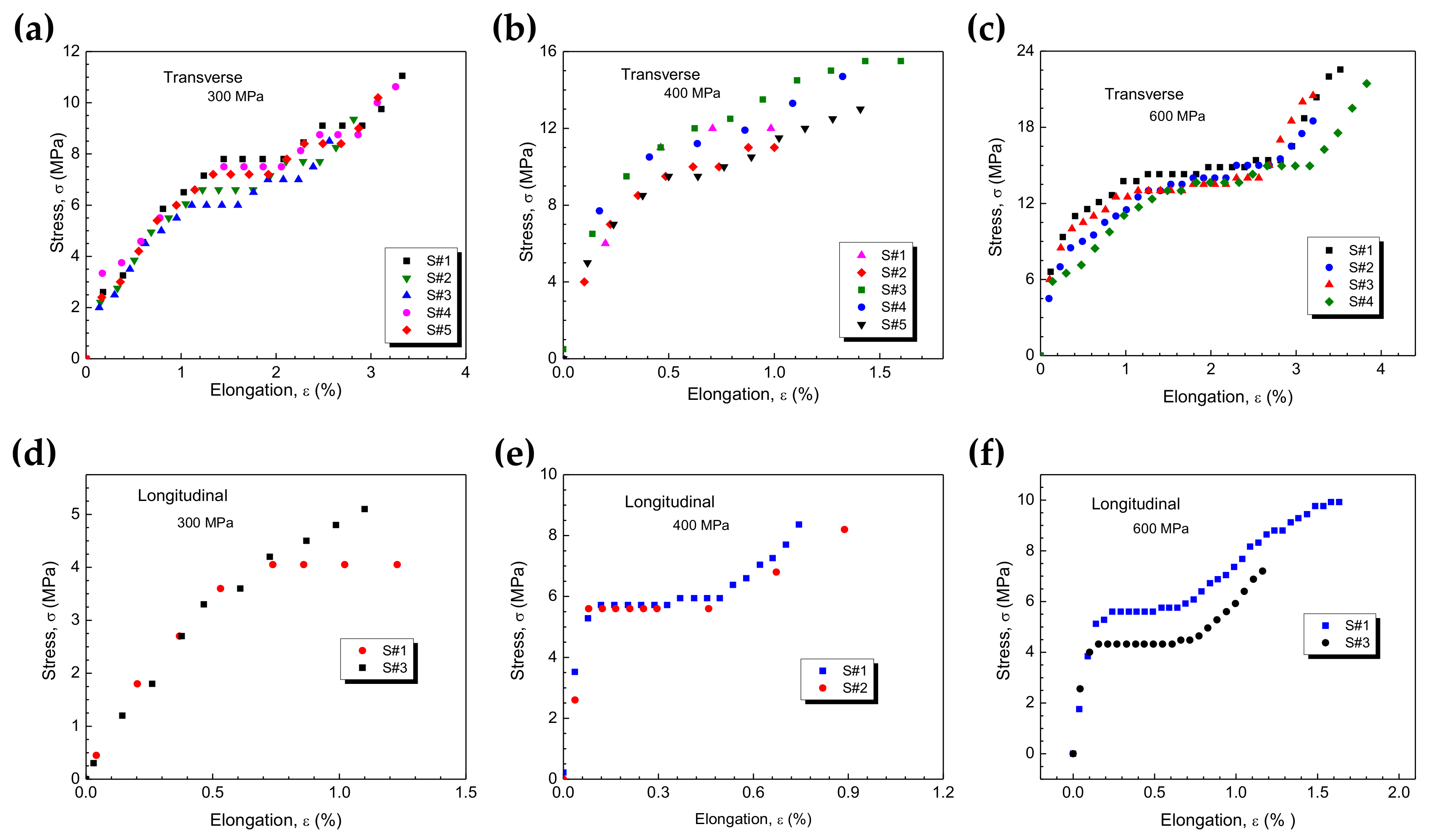
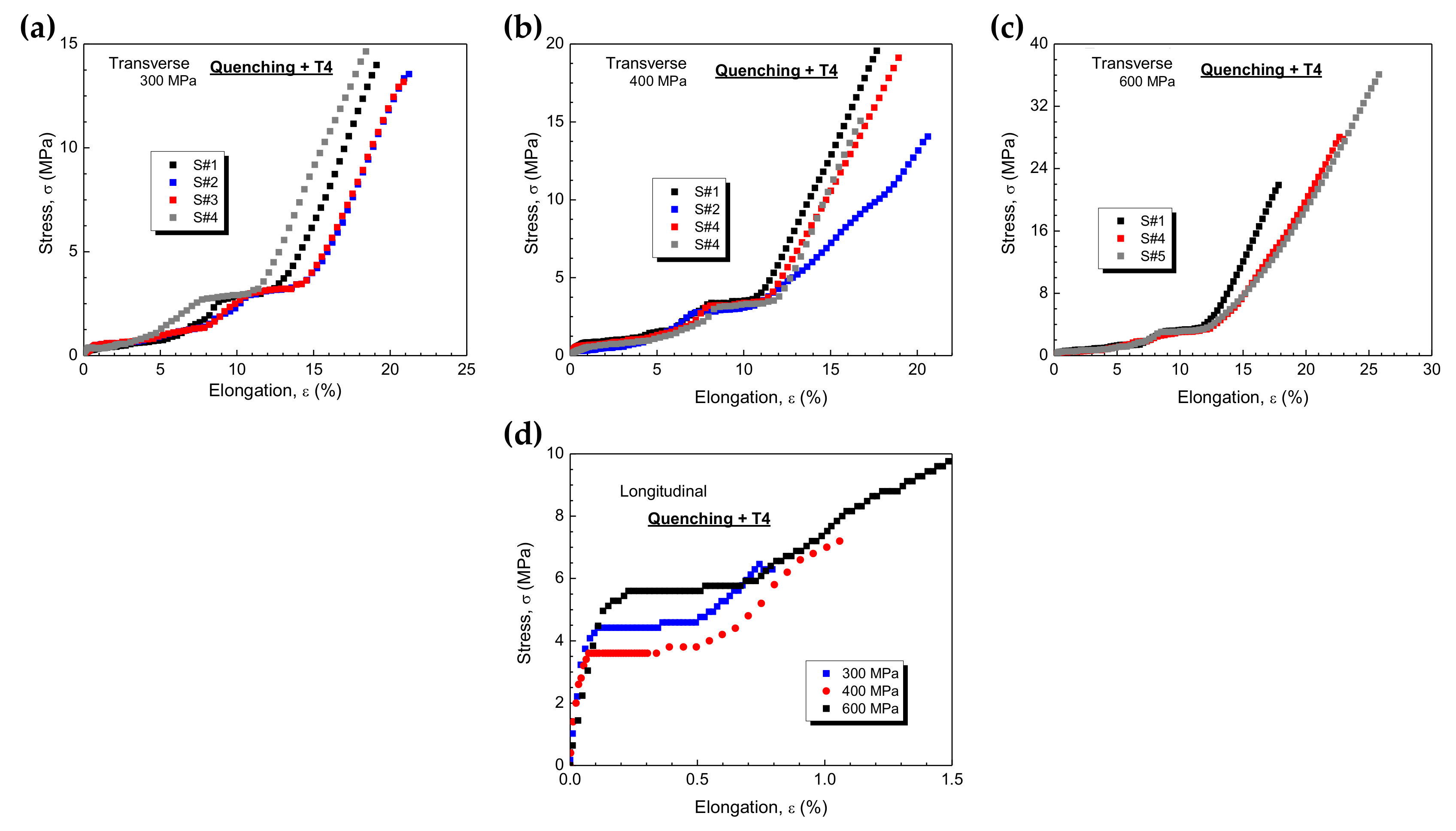
3.3.1. Tensile Strengths and Heat Treatments

Figure 7 presents the experimental results for the tensile strength of transverse and longitudinal samples. In Figure 7a–c, the curves corresponding to transverse samples are shown for compaction pressures of 300, 400, and 600 MPa. Since reproducibility was confirmed, only duplicate results for the longitudinal samples were considered, which are shown in Figure 7d–f for the same compaction pressures. Because all samples in Figure 7 were sintered at 540 °C for 1 h and air-cooled to around 27 °C, the role of compaction pressure and direction on the tensile strength can be directly analyzed.
Figure 8 summarizes the results obtained from examining both transverse and longitudinal samples, representing the tensile strengths of the Al–4Cu samples after sintering followed by water quenching and subsequent natural aging (T4) for approximately 30 days. Figure 8a–c displays the triplicate results for the transverse Al–4Cu samples at compaction pressures of 300, 400, and 600 MPa, respectively. Figure 8b presents the combined results of the longitudinal samples.
Table 1 provides a comparison of the tensile strengths of both the transverse and longitudinal samples of the Al–4Cu alloy samples. For the sintered samples, an increase of approximately 30% in compaction pressure (from 300 to 400 MPa) leads to a quasi-linear increase in ultimate tensile strength (UTS) from 11 to 15 MPa. Similarly, when the compaction pressure is raised from 400 to 600 MPa (a 1.5× increase), the same linear trend is observed. This indicates that doubling the compaction pressure results in an approximate 2× increase in UTS. However, certain limitations must be considered, such as the dimensions of the components and dies within the press, as well as the feasibility of acquiring a press with high pressing capacity. It is worth noting that compaction pressures ranging between 100 and 600 MPa are commonly employed in industrial applications.
The UTS values of the longitudinal samples also increase by approximately 1.5× with an increase in compaction pressure. In contrast, the UTS and elongation (e) values of the transverse samples are approximately 2× higher than those of the longitudinal samples. The yield strength (YS) results of the longitudinal samples are not affected by the compaction pressure, which seems to be associated with the compaction direction and the resulting anisotropy.
Previous studies [7,18,19] have indicated that a bridging effect is prevalent during tension in the transverse direction. This effect not only leads cracks to deflect but also facilitates their propagation through the elongated particles in the transverse direction. This induces frictional resistance, leading to larger contacts perpendicular to the direction of compaction compared to those in other directions [7].
It is important to note that the UTS values obtained in this study are relatively lower compared to those typically achieved in as-cast alloys. Gokçe and Findik [32] have obtained comparable UTS values while investigating Al powder samples, achieving a densification of approximately 91% by applying a compaction pressure of 490 MPa and sintering for 2 h. They also noted that when sintering for 6 h, the tensile strengths reached approximately 240 MPa. Similarly, low UTS (~15 MPa) are achieved for atomized Al powders when adopting a conventional powder metallurgy route [33].
This study focuses on investigating anisotropy, specifically examining how different compaction directions impact the mechanical response. It is worth noting that Galen and Zavaliangos [7] also explored anisotropy in low-alloy steel powders and obtained tensile strengths lower than those typically achieved in as-cast low alloy steel. When considering the potential use of powder particles from recycling processes in conjunction with heat treatments, however, an environmentally-friendly aspect comes into play. Furthermore, it is crucial to emphasize the need for systematic planning of the mechanical forces (be it compressive, tensile, or a combination) in the final application.
After analyzing the experimental results of the transverse and T4-treated samples, it became evident that there is an improvement in the UTS and elongation values. Notably, this improvement is more significant when a compaction pressure of 600 MPa is applied. This difference arises because the UTS results at compaction pressures of 300 and 400 MPa are technically similar. Conversely, a notable increase of 25–30% in UTS and a substantial six-fold increase in elongation are observed when applying a compaction pressure of 600 MPa.
While it is well-known that natural aging significantly improves mechanical properties, the applied compaction pressure also plays an important role in the final properties when compacting, sintering, and heat-treating (T4) recycled powders. This is linked to elongated particles that create bridging effects, primarily impacting elongation. It is important to note that various microstructural factors, common in as-cast materials (e.g., solute content, dendritic spacing, secondary phases, etc.), also contribute synergistically to enhancing the mechanical response. Galen and Zavaliangos [7] have also observed that the bridging effect is amplified in the transverse direction, resulting in higher frictional resistance along the sides of elongated particles compared to the longitudinal samples.
When assessing longitudinal samples, it is evident that T4 heat treatment does not yield any significant improvements in the resulting properties. This observation may be related to the morphology of compacted particles. A comparison of the resulting morphologies shown in Figure 5 and Figure 6 suggests that longitudinal samples tend to be more spheroidal than their transverse counterparts. This observation aligns with our understanding of the bridging effect. It is essential to highlight that the impact of heat treatment on mechanical behavior varies depending on the compaction direction, demonstrating anisotropic strength. However, two aspects require further clarification: first, it is crucial to investigate anisotropy in compression; second, it is necessary to confirm the phases formed during T4 treatment. This is because the resulting microstructures often include different phases of Al2Cu (e.g., θ, θ’, θ”). These phases can be coherent, semi-coherent, or incoherent with respect to the Al-rich matrix, significantly influencing the final properties. The following section will assess and discuss the anisotropic compressive strengths associated with heat treatments.

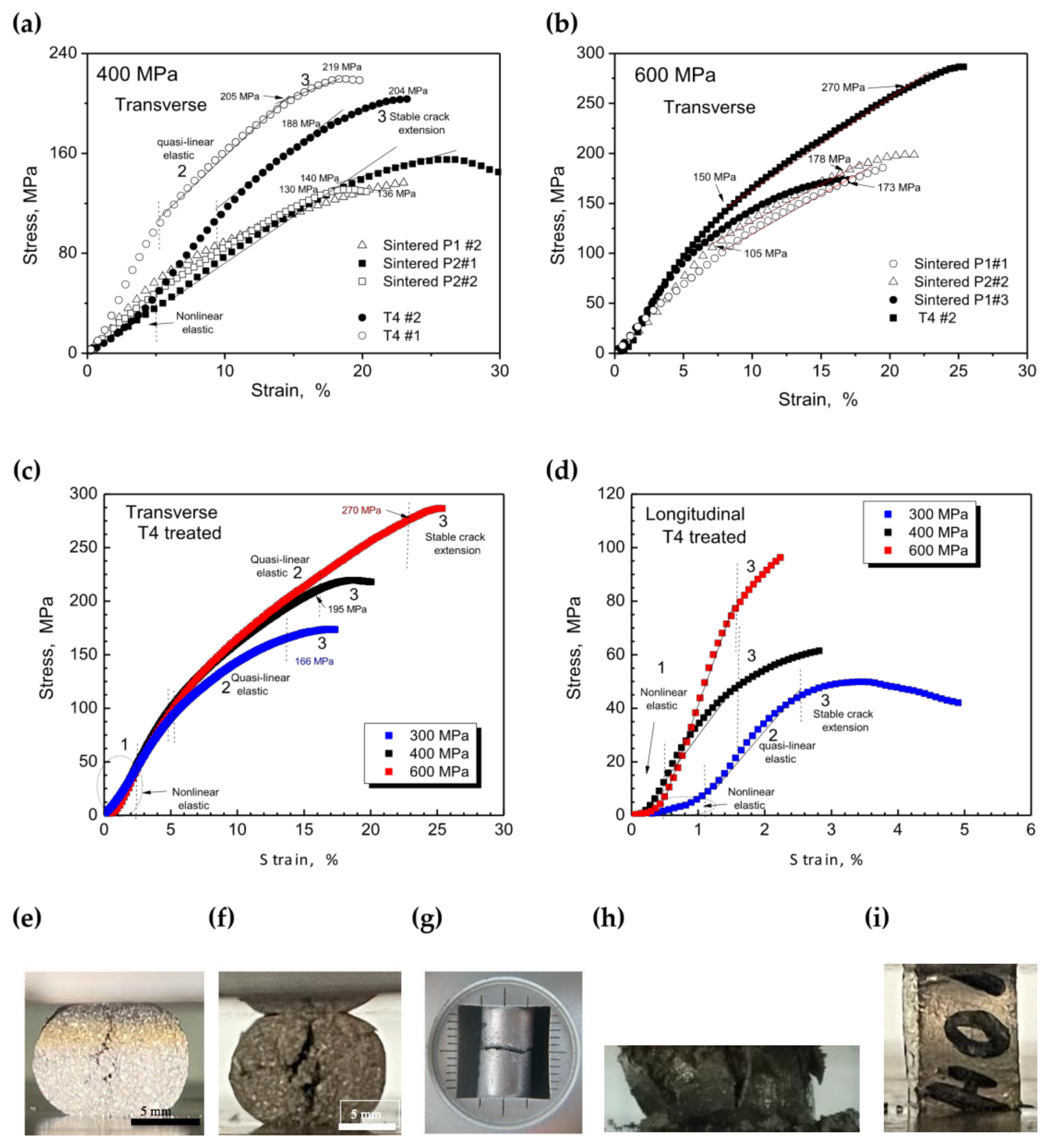
3.3.2. Compressive Strengths and Heat Treatments

Figure 9a,b presents the results of the compressive tests performed on transverse samples subjected to sintering and T4 treatment. We observe two different positions, P1 and P2 (Figure 1e), when referring to transverse samples. These P1 and P2 samples demonstrate very similar reproducibility.
Figure 9c,d depicts the compressive strengths of transverse and longitudinal samples after undergoing T4 treatment, considering three distinct compaction pressures. To facilitate comparison, Table 2 presents the ultimate compressive strength (UCS) values obtained for both sintered and T4-treated samples.
Similar to what was observed for the tensile strength, increasing the compaction pressure by roughly 1.5 times also leads to a proportional increase in the compressive response. Notably, Table 2 shows that transverse samples exhibit UCS values that are at least twice as high as those of longitudinal samples. Furthermore, the UCS values are at least 1.2 times higher than the yield strength (YS). The YS values are determined when the material enters the quasi-linear elastic domain. Similar UCS values were also observed for an Al–5 wt.%Cu alloy using 430 MPa [17,19].
Brazilian indirect tensile tests were carried out on the longitudinal samples according to the Hertz equation [7,32,33]. The obtained values for diametrical compression ( D C ) are reported in Table 2 and were calculated using D C = 2 F / π L D , where F , L , and D are the load at failure, initial length, and diameter of the sample, respectively [7]. The Hertz equation is valid for isotropic elastic materials that undergo brittle failure [7], which is the case of our recycled alloys. This is evident when comparing the calculated DC values (Table 2) with the tensile strength obtained from transverse samples. Interestingly, even though the longitudinal samples are compacted along their length, the indirect tensile strength yields similar values to the transverse samples tested under perpendicular tension. This is further supported by comparing the error ranges and “pure” tensile strength values in Table 1 (11 ± 1, 15 ± 1 and 23 ± 1 MPa) with the DC values in Table 2 (8.6 ± 3, 11.6 ± 3 and 23.2 ± 0.8 MPa). Figure 9e,f provides typical images of longitudinal samples after compression. These images reveal boundaries between deformed particles and the initiation of cracks parallel to the applied load. Figure 9g,h depicts typical images after tensile and compressive tests on longitudinal samples, respectively. Figure 9i displays a picture taken after compressing a transverse sample up to when a stable stress–strain curve is obtained.
Jonsen et al., in their study of diametrical measurements, presented a sequence of images related to the load curve of the tested material [34]. They identified the moment and position on the load curve corresponding to crack initiation. Although they used force–displacement diagrams, three distinct regions were identified: region 1 represents nonlinearity, followed by a quasi-linear elastic region (region 2), and region 3 represents crack propagation. The cracks grow steadily through the sample, and the load reaches values corresponding to YS, while unstable crack propagation continues until a maximum value is reached. This maximum value does not represent the UCS. It is worth noting that UCS and YS are derived from the experimental curves by defining limits between regions 2 and 3 and between 1 and 2, respectively. We consider triplicate or duplicate curves to include at least three points at the interface of these regions to calculate the average values, as shown in Table 2.
Both the longitudinal and transverse samples exhibit similar nonlinear regions, regardless of the compaction pressure applied. This observation appears to be related to the previously mentioned bridging effect. Due to the high interface between the elongated and deformed particles, the region corresponding to elastic (or quasi-elastic) behavior is favored in the samples with more pronounced elongated particles, as observed in Figure 9c,d.

3.3.3. Mechanical Behavior Correlations

Figure 10a,b presents the YS, UTS, and UCS data as a function of compaction pressures for both transverse and longitudinal samples. Notably, the transverse samples exhibit anisotropic strength. When comparing UCS and UTS values, we observe a nonlinear relationship, as shown in Figure 10c. This behavior can be described by a single logarithmic equation ( UCS = 64 ln UTS 80 ) that applies to both longitudinal and transverse samples. This confirms that the morphology and chemical composition of the used powders are similar. Isotropic materials, such as multidirectional solidified as-cast alloys, typically exhibit a linear relationship between UCS and UTS.
The anisotropy ratio, often referred to as strength anisotropy, is quantified by comparing the maximum and minimum values of mechanical behavior, a method previously described by Galen and Zavaliangos [7,9]. For plastically deformable materials, the anisotropy ratio is typically less than 1 and decreases with increasing densification.
Figure 10c,d depicts the strength anisotropy ratios as a function of the applied compaction pressures. The degree of anisotropy was obtained by comparing the UCS and UTS ratios between transverse and longitudinal samples. Galen and Zavaliangos [7] have also shown that most materials with ductile behavior tend to have an anisotropy ratio lower than 1. Moreover, the anisotropy ratio decreases as densification increases [7]. The samples examined in our study did not exhibit ratios higher than 1.
Figure 10d shows the anisotropy ratios for longitudinal and transverse samples. To summarize these tendencies, we have included Table 3. Interestingly, longitudinal samples in sintered and T4-treated conditions exhibited decreasing trends with increasing compaction pressures. Conversely, the transverse samples show increasing trends. Within certain limitations, we can observe that transverse samples tend to become more isotropic than longitudinal ones. This trend is evident in both Table 3 and Figure 10d. Transverse samples exhibit slightly increasing anisotropy ratios, which are very similar. In contrast, longitudinal samples exhibit non-linear decreasing trends with greater variation. Additionally, air-cooled longitudinal samples are more isotropic than water-quenched ones. Among the examined samples, the highest anisotropy ratio is observed for the water-quenched sample compacted at 600 MPa.
Galen and Zavaliangos [7] have noted that strength anisotropy becomes more pronounced with increasing density, which is achieved through increasing compaction pressure. In our investigation, however, this increased anisotropy is observed only in the longitudinal samples. Furthermore, they observed that material with a non-equiaxed (acicular) morphology tend to exhibit higher anisotropy than those with equiaxed morphology.
In our study, we found that the morphology of the compacted powders in the longitudinal samples tends to be more spheroidal compared to that of transverse samples. This aligns with the observations made by Galen and Zavaliangos. Xu et al. [9] have also explored the degree of anisotropy using Young’s modulus and compressive strength and found that anisotropy decreases as compaction pressure increases. In our experiment, this trend is evident only in the longitudinal samples. These findings suggest that morphology, compaction pressure, and heat treatment collectively influence strength anisotropy.
When comparing the X-ray diffraction (XRD) patterns, we observe that the green, sintered, and T4-treated samples share very similar phases. Figure 11a shows the XRD analysis of the green powder samples, sintered powders, and T4-treated powders, which were obtained from drilled compacted and treated specimens. The diffraction intensity reveals that the peaks corresponding to Al crystallographic planes (111), (200), (220), (311), and (222) (JCPDS # 01-1180) are present. Figure 11b shows that between angles 15° and 50°, the Bragg’s planes (110), (200), (210), (211), (403), (220), (112), (310), and (202) (JCPDS # 01-1180), which correspond to Al2Cu intermetallic crystallographic planes, are present, as previously reported [17,19,23,24,25,26,35,36,37,38]. It is also observed that the coherent Al2Cu phases, designated as θ’ and θ”, are not substantially identified at angles ~23° and ~31° [17,38].
The XRD pattern of the T4-treated sample differs mainly in the presence of the main θ Al2Cu phases, specifically at (111), (220), (112), (310), and (202). These phases are clearly observed in both the sintered and as-cast samples, but not substantially in the T4-treated sample. Figure 11c presents the XRD patterns of the green sample in both powder and consolidated conditions (samples #1 and #2). It is important to note that the powder sample is obtained from the as-cast alloy after drilling. The consolidated samples are obtained after compaction (e.g., using 600 MPa), and samples #1 and #2 represent the top and bottom analysis of the same sample, respectively.
These comparisons aim to illustrate that there are no significant differences when comparing powder and compacted samples. The compacted samples exhibit more pronounced peaks corresponding to the θ’ and θ” phases, as well as other phases at angles higher than 50°, as shown in Figure 11c. Additionally, Figure 11d confirms that the XRD patterns remain unchanged after heat treatment and testing under compressive loading.
The most notable changes are observed in the reduced intensity of peaks related to the incoherent Al2Cu on planes (110) and (200) at 21° and 29°, as depicted in Figure 11.
This can be attributed to the fact that during the solution treatment, a homogeneous solid solution (α-Al phase) with Cu dissolved in the Al matrix is formed. Subsequently, the quenching leads to the formation of a supersaturated solid solution of the θ phase. This mechanism is commonly described in the literature [35,36,37,38]. It is reported that a typical transition in Al–Cu alloys is from a supersaturated solution to coherent Guinier Preston (GP) zones, followed by intermediate coherent (θ”) and semi-coherent (θ’) phases, and to a more stable (θ) phase [36,38]. Based on these observations and the analysis of the XRD patterns, we can infer that the T4-treated samples undergo partial dissolution of their Al2Cu phases, primarily in the regions corresponding to planes (110) and (200) at ~21° and ~29°. Additionally, the intensity peaks of Al (e.g., at planes (111), (200), and (220)) have shown a proportional and comparative increase, indicating the dissolution of Cu and the formation of a supersaturated solution, along with the presence of some residual Al2Cu phases. It is worth noting that the complete dissolution or subsequent precipitation did not occur after water quenching or natural aging. These findings help to explain the improved mechanical behavior.
Zhang et al. [38] have recently demonstrated the presence of the three distinct Al2Cu phases, i.e., θ’ and θ”, in as-cast 2219 Al–Cu alloys. The TEM images revealed that the θ phase has a more spheroidal shape (5 to 10 µm) compared to the θ’ and θ” phases, which exhibit a needle-like morphology and are finer than the θ phase. Zhang et al. [38] also found that after a solution treatment at 538 °C for 2 h, which is similar to the treatment applied in this study (540 °C for 1 h), both the θ’ and θ” Al2Cu intermetallics are completely dissolved into the Al matrix. The UTS results obtained by Zhang et al. [34] are similar to those obtained in this study. It is important to note that the 2219 Al–Cu alloy used by Zhang et al. [38] has a higher Cu content, which can contribute to the enhanced mechanical behavior. Additionally, the alloy samples were cast using ultrasonic casting [38], resulting in a finer microstructural arrangement and, consequently, improved mechanical behavior. This comparison is intended solely to illustrate the existence of θ’ and θ” Al2Cu phases and their dissolution processes during the solution and heat treatments.

4. Conclusions

The experimental results obtained from compaction and heat treatment of Al–Cu alloy powders lead to the following key conclusions:
  • Distinctive Morphologies: Compacting the powders in different directions (longitudinal and transverse) results in unique morphologies. Longitudinal compaction leads to spheroidal-like shapes, while transverse compaction results in elongated-like shapes. These morphological differences contribute to a bridging effect among the powder particles, ultimately impacting mechanical behavior. Notably, sintered transverse and longitudinal samples exhibit similar deformation capacity, but the transverse samples achieve higher densification (~90%) compared to longitudinal samples (~87%). Therefore, the compaction direction significantly influences both densification and resulting mechanical properties.
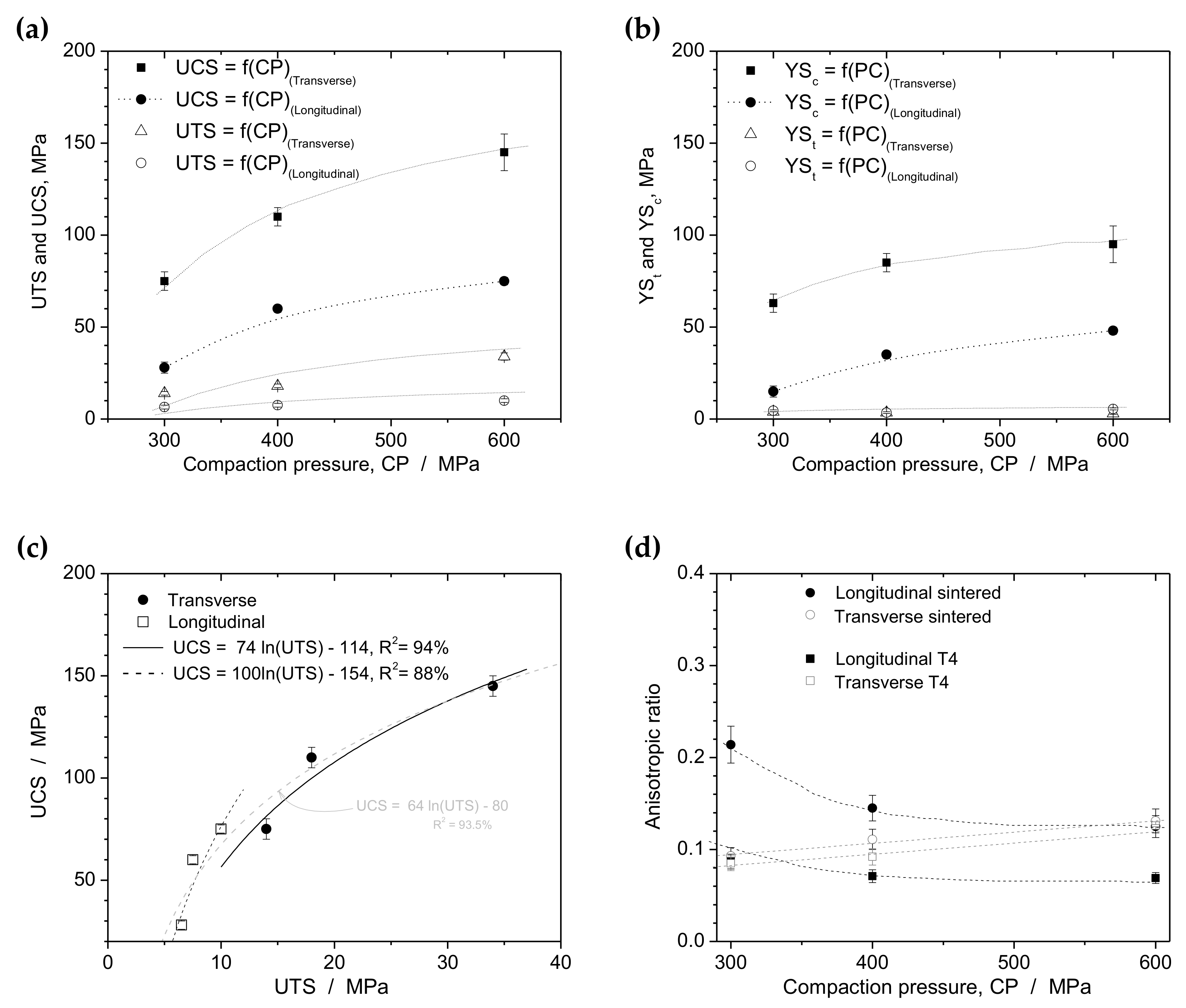
  • T4 Treatment Impact: T4-treated samples consistently exhibit the highest values of ultimate tensile strength (UTS) and ultimate compressive strength (UCS) compared to other experimental conditions. As expected, UCS values are higher than UTS values. In general, transverse samples outperform longitudinally compacted samples in terms of mechanical performance.
  • Anisotropic Ratios: Anisotropic ratios, which quantify the degree of anisotropy, are determined by comparing the maximum values of UCS and UTS for each compaction direction and heat treatment used in this study. Transverse samples display relatively consistent anisotropic ratios, with a slight increasing trend as compaction pressure rises. Conversely, longitudinal samples show non-linear decreasing trends in anisotropic ratios with increasing compaction pressure. The ratios for longitudinal samples exhibit more dispersion compared to transverse samples. Consequently, sintered longitudinal samples tend to be more isotropic than T4-treated longitudinal samples.
  • Morphological Influence: The resulting morphology of the longitudinal samples, characterized by a more spheroidal shape compared to transverse samples, is closely linked to the compaction direction. This observation underscores the significance of the initial morphology, compaction load, and heat treatment in impacting strength anisotropy. These findings imply that recycled powder particles from conventional machining processes can be used to manufacture components with specific mechanical requirements. This approach not only offers environmental benefits by reducing metallic fumes but also reduces the energy consumption associated with melting processes.
Overall, this study underscores how compaction direction and heat treatment significantly impact the mechanical behavior and anisotropy of Al–Cu alloy powders. It also highlights the potential of using recycled powder particles and environmentally friendly production methods for manufacturing components with desired mechanical properties.

Author Contributions

R.S.B. has prepared and treated all samples. R.S.B. and R.F.G.B. have carried out the mechanical characterization and treated the data. A.D.B. has carried out the XRD measures and treated the obtained data. E.P. has helped with the general organization and with the English written manuscript. W.R.O., R.S.B., A.D.B., and E.P. have contributed to the general organization of the experiments and analyses. W.R.O. and A.D.B. have written and organized the proposed manuscript. All authors have read and agreed to the published version of the manuscript.

Funding

Financial support was provided by FAEPEX-UNICAMP (#2252/23), CAPES (Coordination for the Improvement of Higher Education Personnel) (Ministry of Education, Brazil, Grant #1), and CNPq (The Brazilian Research Council) (Grants #407595/2022-8; #313272/2021-2, and 310010/2020-9).

Institutional Review Board Statement

Not applicable.

Informed Consent Statement

Not applicable.

Data Availability Statement

All research data supporting this publication are directly available within this publication.

Acknowledgments

Acknowledgments are also provided to Luiz A. Garcia (technician department) whose contribution included technical advice and equipment organization.

Conflicts of Interest

The authors declare no conflict of interest.

References

  1. Guo, M.X.; Wang, M.P. Effects of particle size, volume fraction, orientation and distribution on the high temperature compression and dynamic recrystallization behaviors of particle-containing alloys. Mat. Sci. Eng. A 2012, 546, 15–25. [Google Scholar] [CrossRef]
  2. Loidolt, P.; Ulz, M.H.; Khinast, J. Prediction of the anisotropic mechanical properties of compacted powders. Powder Technol. 2019, 345, 589–600. [Google Scholar]
  3. Akisanya, A.R.; Cocks, A.C.F.; Fleck, N.A. The yield behavior of metal powders. Int. J. Mech. Sci. 1997, 39, 1315–1324. [Google Scholar] [CrossRef]
  4. Vityaz, P.A.; Sheleg, V.K.; Kaptsevich, V.M.; Kusin, R.A.; Gurevich, A.A. Plasticity condition of anisotropic high-porosity powder materials. Poroshkovaya Metall. 1984, 9, 1–5. [Google Scholar]
  5. Weston, J.E. Origin of strength anisotropy in hot-pressed silicon nitride. J. Mater. Sci. 1980, 15, 1568–1576. [Google Scholar] [CrossRef]
  6. Zavaliangos, A.; Bouvard, D. Numerical simulation of anisotropy in sintering due to prior compaction. Met. Powder Rep. 2002, 57, 39. [Google Scholar] [CrossRef]
  7. Galen, S.; Zavaliangos, A. Strength anisotropy in cold compacted ductile and brittle powders. Acta Mater. 2005, 53, 4801–4815. [Google Scholar] [CrossRef]
  8. Cao, L.; Zeng, W.; Xie, Y.; Liang, J.; Zhang, D. Effect of powder oxidation on the anisotropy in tensile mechanical properties of bulk Al samples fabricated by spark plasma sintering. Mater. Sci. Eng. A 2019, 764, 138246. [Google Scholar]
  9. Brünig, M.; Gerke, S.; Koirala, S. Biaxial Experiments and Numerical Analysis on Stress-State-Dependent Damage and Failure Behavior of the Anisotropic Aluminum Alloy EN AW-2017A. Metals 2021, 11, 1214. [Google Scholar] [CrossRef]
  10. Reis, D.A.P.; Couto, A.A.; Domingues, N.I., Jr.; Hirschmann, A.C.O.; Zepka, S.; Neto, C.M. Effect of artificial aging on the mechanical properties of an aerospace aluminum alloy 2024. Defect Diffus. Forum 2012, 326–328, 193–198. [Google Scholar] [CrossRef]
  11. Hu, X.; Bahl, S.; Shyam, A.; Plotkiwski, A.; Milligan, B.; Allard, L.; Haynes, J.A.; Ren, Y.; Chuang, A. Repurposing the q (Al2Cu) phase to simultaneously increase the strength and ductility of an additively manufactured Al-Cu alloy. Mater. Sci. Eng. A 2022, 850, 143511. [Google Scholar] [CrossRef]
  12. Iswanto, P.T.; Pambekti, A. Heat treatment T4 and T6 effects on mechanical properties in Al-Cu alloy after remelt with different pouring temperatures. Metalurgija 2020, 59, 171–174. [Google Scholar]
  13. Ying, P.; Lin, C.; Liu, Z.; Bai, S.; Levchenko, V.; Zhang, P.; Wu, J.; Yang, T.; Huang, M.; Yang, G.; et al. Pre-Aging Effect on the Formation of Ω Phase and Mechanical Properties of the Al-Cu-Mg-Ag Alloy. Metals 2022, 12, 1208. [Google Scholar] [CrossRef]
  14. Feng, Y.; Chen, X.; Hao, Y.; Chen, B. Ageing evolution process of the q’-phase in Al-Si-Cu-Mg alloys: Atomic-scale observations and first-principles calculations. J. Alloys Compd. 2023, 968, 171787. [Google Scholar] [CrossRef]
  15. Rivera-Cerezo, H.; Gaona-Tiburcio, C.; Cabral-Miramontes, J.; Bautista-Margulis, R.G.; Nieves-Mendoza, D.; Maldonado-Bandala, E.; Estupiñán-López, F.; Almeraya-Calderón, F. Effect of Heat Treatment on the Electrochemical Behavior of AA2055 and AA2024 Alloys for Aeronautical Applications. Metals 2023, 13, 429. [Google Scholar] [CrossRef]
  16. Cai, Y.; Su, Y.; Liu, K.; Hua, A.; Wang, X.; Cao, H.; Zhang, D.; Ouyang, Q. Effect of Sc microalloying on fabrication, microstructure and mechanical properties of SiCp/Al-Cu-Mg-Sc composites via powder metallurgy. Mater. Sci. Eng. A 2023, 877, 145152. [Google Scholar] [CrossRef]
  17. Meyer, Y.A.; Bonatti, R.S.; Costa, D.; Bortolozo, A.D.; Osório, W.R. Compaction pressure and Si content effects on compressive strengths of Al/Si/Cu alloy composites. Mater. Sci. Eng. A 2019, 770, 138547. [Google Scholar] [CrossRef]
  18. Bonatti, R.S.; Siqueira, R.R.; Padilha, G.S.; Bortolozo, A.D.; Osório, W.R. Distinct Alp/Sip composites affecting its densification and mechanical behavior. J. Alloys Compd. 2018, 757, 434–447. [Google Scholar] [CrossRef]
  19. Gao, Z.H.; Gao, H.J.; Wu, Q. Experiment and mechanism investigation o the efect of heat treatment on residual stress and mechanical properties of SiCp/Al-Cu-Mg composites. Mater. Sci. Eng. A 2023, 884, 145555. [Google Scholar] [CrossRef]
  20. Fogagnolo, J.; Robert, M.; Torralba, J. Mechanically alloyed AlN particle-reinforced Al-6061 matrix composites: Powder processing, consolidation and mechanical strength and hardness of the as-extruded materials. Mater. Sci. Eng. A 2006, 426, 85–94. [Google Scholar] [CrossRef]
  21. Espinosa-Méndez, C.; Maquieira, C.P.; Arias, J.T. The impact of ESG performance on the value of family firms: The moderating role of financial constrainsts and agency problems. Sustainability 2023, 15, 6176. [Google Scholar] [CrossRef]
  22. Kurz, W.; Fisher, D.J. Fundamentals of Solidification; Trans Tech Publications: Zurich, Switzerland, 1992. [Google Scholar]
  23. Hamza, H.M.; Deen, K.M.; Haider, W. Microstructural examination and corrosion behavior of selective laser melted and conventionally manufactured Ti6Al4V for dental applications. Mater. Sci. Eng. C 2020, 113, 110980. [Google Scholar] [CrossRef]
  24. The Materials Project. Al2Cu/mp-998. Available online: https://next-gen.materialsproject.org (accessed on 15 August 2023).
  25. Alam, S.N.; Shrivastava, P.; Panda, D.; Gunale, B.; Susmitha, K.; Pola, P. Synthesis of Al2Cu intermetallic compound by mechanical alloying. Mater. Today Commun. 2022, 31, 103267. [Google Scholar] [CrossRef]
  26. Zhou, J.; Duszczyk, J. Preparation of Al-20Si-4.5Cu alloy and its composite from elemental powders. J. Mater. Sci. 1999, 34, 5067–5073. [Google Scholar] [CrossRef]
  27. Ramberger, R.; Burger, A. On the application of the Heckel and Kawakita equations to powder compaction. Powder Technol. 1985, 43, 1–9. [Google Scholar] [CrossRef]
  28. Han, P.; An, X.; Wang, D.; Fu, H.; Yang, X.; Zhang, H.; Zou, Z. MPFEM simulation of compaction densification behavior of Fe-Al composite powders with different size ratios. J. Alloys Compd. 2018, 741, 473–481. [Google Scholar] [CrossRef]
  29. Shi, J.; Hu, Q.; Zhao, X.; Liu, J.; Zhou, J.; Xu, W.; Chen, Y. Densification, microstructure and anisotropic corrosion behavior of Al-Mg-Mn-Sc-Er-Zr alloy processed by selective laser melting. Coatings 2023, 13, 337. [Google Scholar] [CrossRef]
  30. Bouvard, D. Densification behaviour of mixtures of hard and soft powders under pressure. Powder Technol. 2000, 111, 231–239. [Google Scholar] [CrossRef]
  31. Hafizpour, H.R.; Simchi, A. Investigation on compressibility of Al–SiC composite powders. Powder Met. 2008, 51, 217–223. [Google Scholar] [CrossRef]
  32. Gokçe, A.; Findik, F. Mechancial and physical properties of sintered aluminum powders. J. Achiev. Mater. Manufact. Eng. 2008, 30, 157–164. [Google Scholar]
  33. Sweet, G.A.; Brochu, M.; Hexemer, R.L., Jr.; Donaldson, I.W.; Bishop, D.P. Microstructure and mechanical properties of air atomized aluminum powder consolidated via spark plasma sintering. Mater. Sci. Eng. A 2014, 608, 273–282. [Google Scholar] [CrossRef]
  34. Jonsén, P.; Häggblad, H.; Sommer, K. Tensile strength and fracture energy of pressed metal powder by diametral compression test. Powder Technol. 2007, 176, 148–155. [Google Scholar] [CrossRef]
  35. Baiocco, D.; Zhang, Z.; He, Y.; Zhang, Z. Relationship between the Young’s Moduli of Whole Microcapsules and Their Shell Material Established by Micromanipulation Measurements Based on Diametric Compression between Two Parallel Surfaces and Numerical Modelling. Micromachines 2023, 14, 123. [Google Scholar] [CrossRef]
  36. Aguechari, N.; Boudiaf, A.; Ouali, M.O. Effect of artificial aging treatment on microstructure, mechanical properties and fracture behavior of 2017A alloy. Met. Mater. Eng. 2022, 28, 305–318. [Google Scholar] [CrossRef] [PubMed]
  37. Vargas-Martínez, J.; Estela-García, J.E.; Suárez, O.M.; Vega, C.A. Fabrication of a Porous Metal via Selective Phase Dissolution in Al-Cu Alloys. Metals 2018, 8, 378. [Google Scholar] [CrossRef]
  38. Zhang, Y.; Li, R.; Chen, P.; Li, X.; Liu, Z. Microstructural evolution of Al2Cu phase and mechanical properties of the large-scale Al alloy components under different consecutive manufacturing processes. J. Alloys Compd. 2019, 808, 151634. [Google Scholar] [CrossRef]
Figure 1. Schematic representation of (a) the compaction die used to produce (b) transverse samples; (c) the double-action compaction die used to produce (d) cylindrical longitudinal samples; and (e) the two perpendicular directions used to characterize the mechanical properties of transverse samples. The red arrows indicate compacting directions, and the blue arrows indicate tensile and compression directions.
Metals 13 01710 g001
Figure 2. (a) Compacted (green) samples disposed inside (b) alumina recipients to sintering. Sintering cycles of (c) air-cooled and (d) water-quenched samples.
Metals 13 01710 g002
Figure 3. (a) Scanning electron micrographs of typical particles obtained by drilling as-cast Al–4Cu alloys. (b,c) Distinct regions of sample in (a). (d,e) Volume fractions of particles in (a) with different lengths and widths.
Metals 13 01710 g003
Figure 4. Experimental results for (a,b) transverse and (c,d) longitudinal samples of green and sintered Al–4Cu alloys. The densification is plotted as a function of compaction pressure (a,c) and the same data fitted by Equation (1) (b,d). (e) Typical micrograph depicting the porosity level of a transverse sample compacted at 600 MPa and sintered.
Metals 13 01710 g004
Figure 5. Typical fracture surfaces of longitudinal samples of the Al–4Cu recycled alloy taken from sections (a) AA and (b) BB. The arrows indicate the direction of the compaction pressure, and the ghost lines illustrate the observed morphology trend of the resulting particles.
Metals 13 01710 g005
Figure 6. Typical fracture surfaces of transverse samples of the Al–4Cu recycled alloy taken from sections (a) CC and (b) DD. The arrows indicate the direction of the compaction pressure, and the ghost lines illustrate the observed morphology trend of the resulting particles.
Metals 13 01710 g006
Figure 7. Stress–strain curves obtained from tensile tests of Al–4Cu samples cooled down via air cooling. The (ac) transverse and (df) longitudinal samples were compacted using pressures of 300, 400, and 600 MPa.
Metals 13 01710 g007
Figure 8. Stress–strain curves obtained from tensile tests of Al–4Cu samples cooled down via water quenching and a T4 heat treatment. The (ac) transverse and (d) longitudinal samples were compacted using pressures of 300, 400 and 600 MPa.
Metals 13 01710 g008
Figure 9. (ad) Stress–strain curves obtained from compression tests of Al–4Cu samples cooled down via water quenching and T4 heat treatment. Results are shown for transverse samples compacted at (a) 400 and (b) 600 MPa, and for both (c) transverse and (d) longitudinal samples after T4 heat treatment. Photograph pictures showing the cracks in longitudinal samples at the (e) beginning and (f) end of Brazilian indirect tensile tests, and at the end of (g) tensile and (h) compressive tests. (i) Picture of a transverse sample barreling under compression.
Metals 13 01710 g009
Figure 10. Summary of mechanical behavior: (a) UTS and UCS; (b) yield tensile (YSt) and compressive (YSc) strengths as a function of compaction pressure (CP); (c) UCS plotted against UTS; (d) the anisotropic ratio (UCS/UTS) as a function of compaction pressure.
Metals 13 01710 g010
Figure 11. Typical X-ray diffraction (XRD) patterns of (a) green, sintered, and T4-treated samples; (b) evidencing phases between 15 and 50°; and (c) green samples after the compaction stage, distinguishing top and bottom surfaces (samples# 1 and #2). (d) Illustration that there are no significant differences in the constituted phases after sintering, T4 treatment, and compressive tests at 600 MPa.
Metals 13 01710 g011aMetals 13 01710 g011b
Table 1. Summarized data for yield strength (YS), ultimate tensile strength (UTS), and elongation (ε) obtained from the stress–strain curves of transverse and longitudinal samples.
Samples SinteredQuenched + T4
TransversalYS, MPaUTS, MPaε, %YS, MPaUTS, MPaε, %
300 MPa7 (±1)11 (±1)3.5 (±0.2)4 (±0.5)14 (±1)18 (±0.2)
400 MPa10 (±0.5)15 (±1)1.5 (±0.2)3.5 (±0.5)18 (±1)19 (±0.2)
600 MPa14 (±0.5)23 (±1)3.6 (±0.2)3.0 (±0.5)34 (±2)23 (±0.2)
LongitudinalYS, MPaUTS, MPaε, %YS, MPaUTS, MPaε, %
300 MPa4.0 (±0.5)6 (±1.0)0.9 (±0.2)4.5 (±0.5)6.5 (±0.5)0.8 (±0.1)
400 MPa4.5 (±0.5)8 (±0.5)0.8 (±0.2)3.5 (±0.5)7.5 (±0.5)1.2 (±0.1)
600 MPa4.5 (±0.5)10 (±0.5)1.3 (±0.3)4.5 (±0.5)10 (±0.5)1.5 (±0.2)
Table 2. Average values of ultimate compressive strength (UCS), yield strength (YS), and load applied in diametrical compression (DC) for transverse and longitudinal samples.
Samples Sintered Quenched + T4
TRANSVERSEYS, MPaUCS, MPaYS, MPaUCS, MPaF, NDC, MPa
300 MPa65 (±5)118 (±6)92 (±5)165(±10)------
400 MPa80 (±10)135 (±10)118 (±5)195 (±10)------
600 MPa105 (±8)175 (±8)150(±10)270 (±10)------
LONGITUDINALYS, MPaUCS, MPaYS, MPaUCS, MPaF, NDC, MPa
300 MPa15 (±2)28 (±5)63 (±5)75 (±6)0.9 (±0.2)8.6 (±3)
400 MPa35 (±2)55 (±5)85 (±5)110 (±8)1.2 (±0.2)11.6 (±3)
600 MPa48 (±4)80 (±8)95 (±10)145 (±10)2.3 (±0.1)23.2 (±0.8)
Table 3. The anisotropic ratio (AR)(*) considering both the sintered and T4 heat-treated samples with respect to longitudinal and transversal conditions versus compaction pressures.
SinteredLongitudinalTransverse
300 MPa0.2140.093
400 MPa0.1450.111
600 MPa0.1250.131
Quenched + T4LongitudinalTransverse
300 MPa0.0870.085
400 MPa0.0710.092
600 MPa0.0690.126
(*) AR = UTS/UCS considering each compaction direction, i.e., longitudinal and transverse. These values are presented in Table 1 and Table 2.
Disclaimer/Publisher’s Note: The statements, opinions and data contained in all publications are solely those of the individual author(s) and contributor(s) and not of MDPI and/or the editor(s). MDPI and/or the editor(s) disclaim responsibility for any injury to people or property resulting from any ideas, methods, instructions or products referred to in the content.

