

Influence of Overheating on High-Cycle Fatigue Characteristics of the Base Metal and Weld Metal of Low-Carbon Steel Welded Joints

 , ,
, ,
Abstract
:1. Introduction
2. Materials and Methods
2.1. Materials
- As delivered;
- After overheating: heating up to 1200 °C at a rate of 200 °C/h; exposure for 3.7 h; and further cooling in the furnace to room temperature.
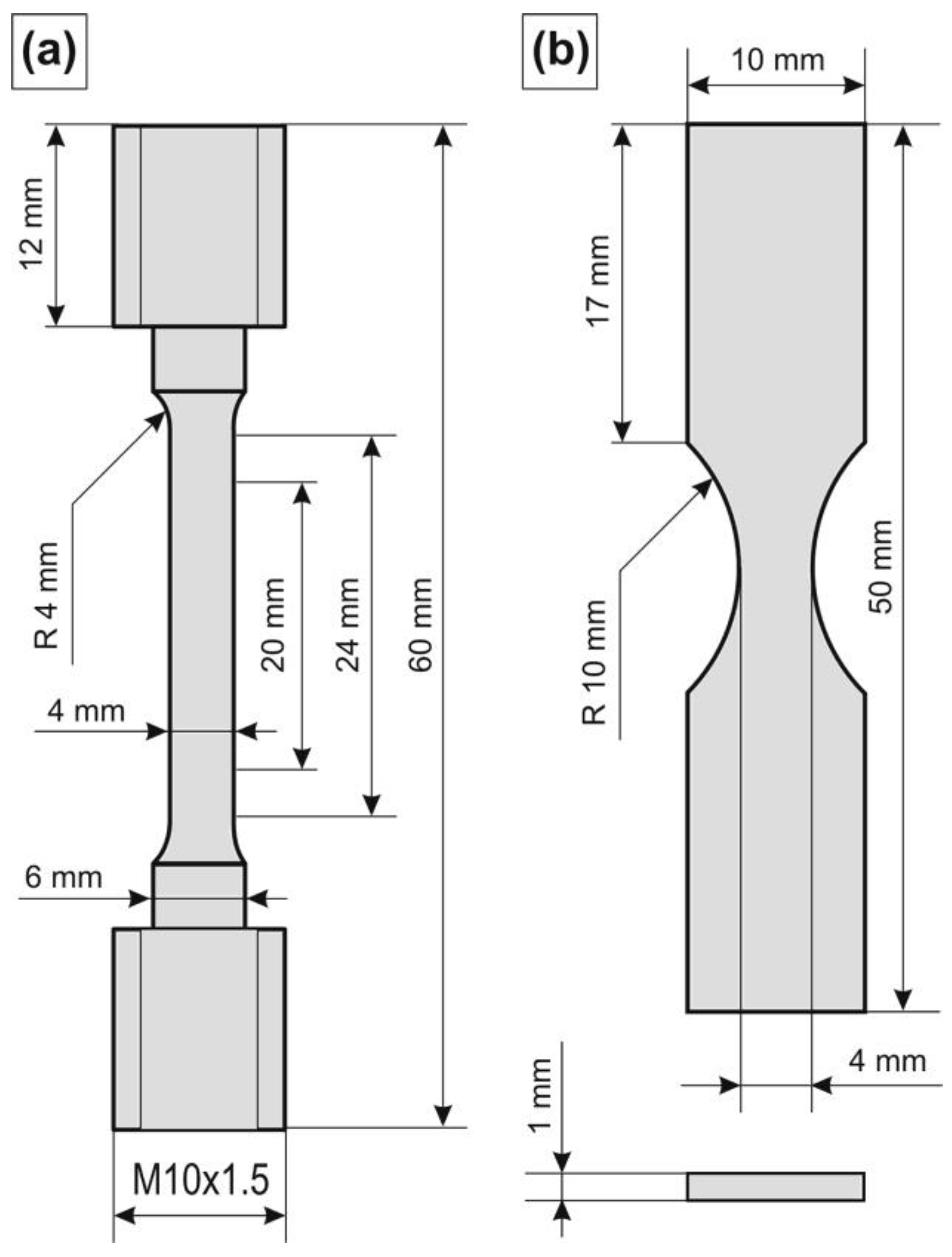
2.2. Methods
3. Results
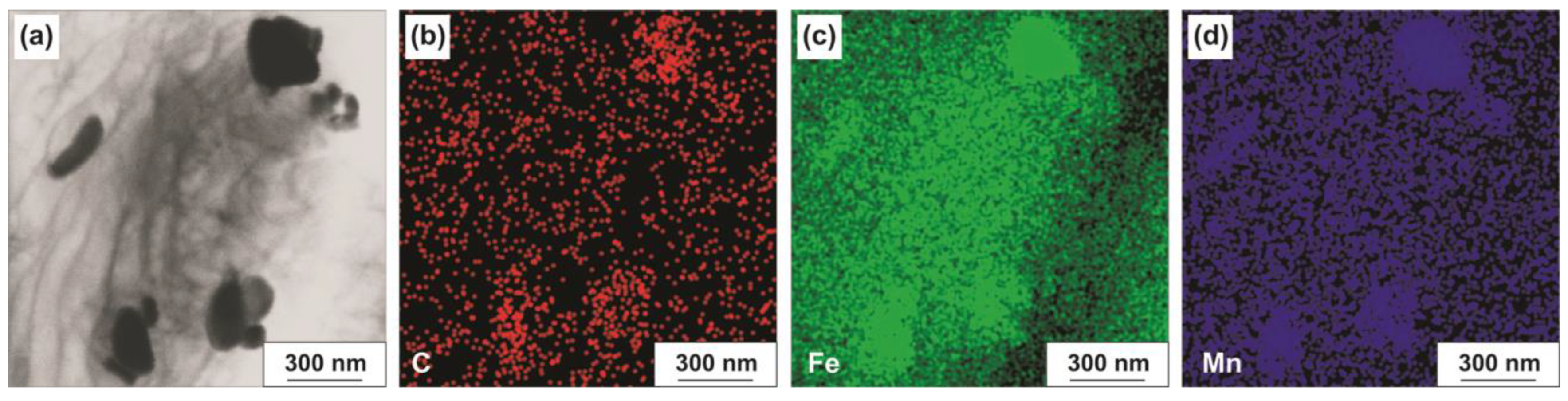
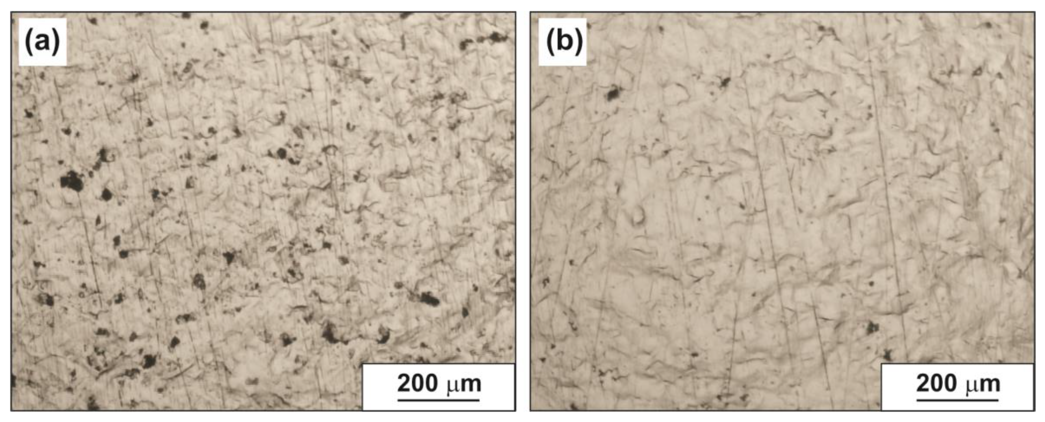
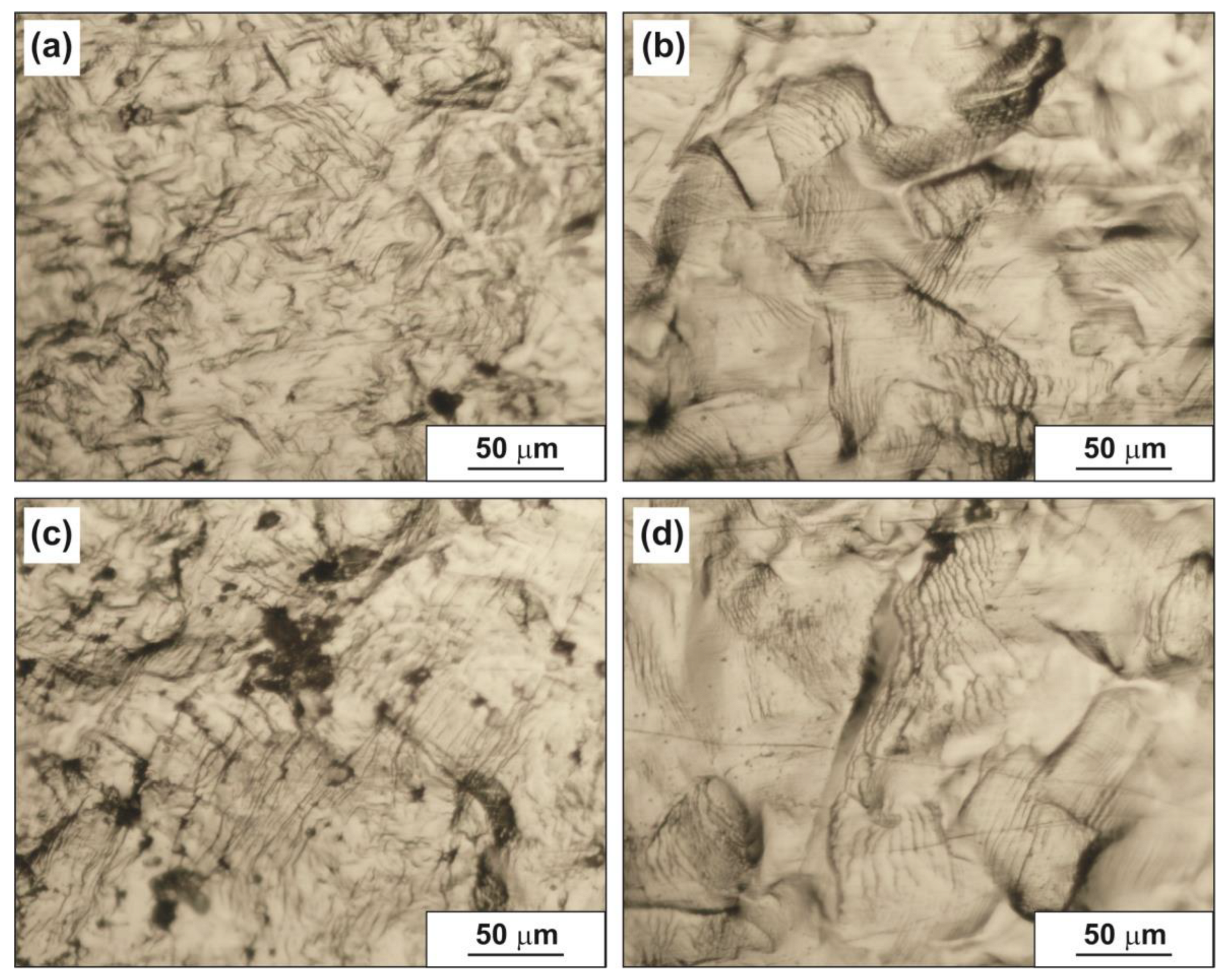
3.1. Microstructure
3.2. Mechanical Properties
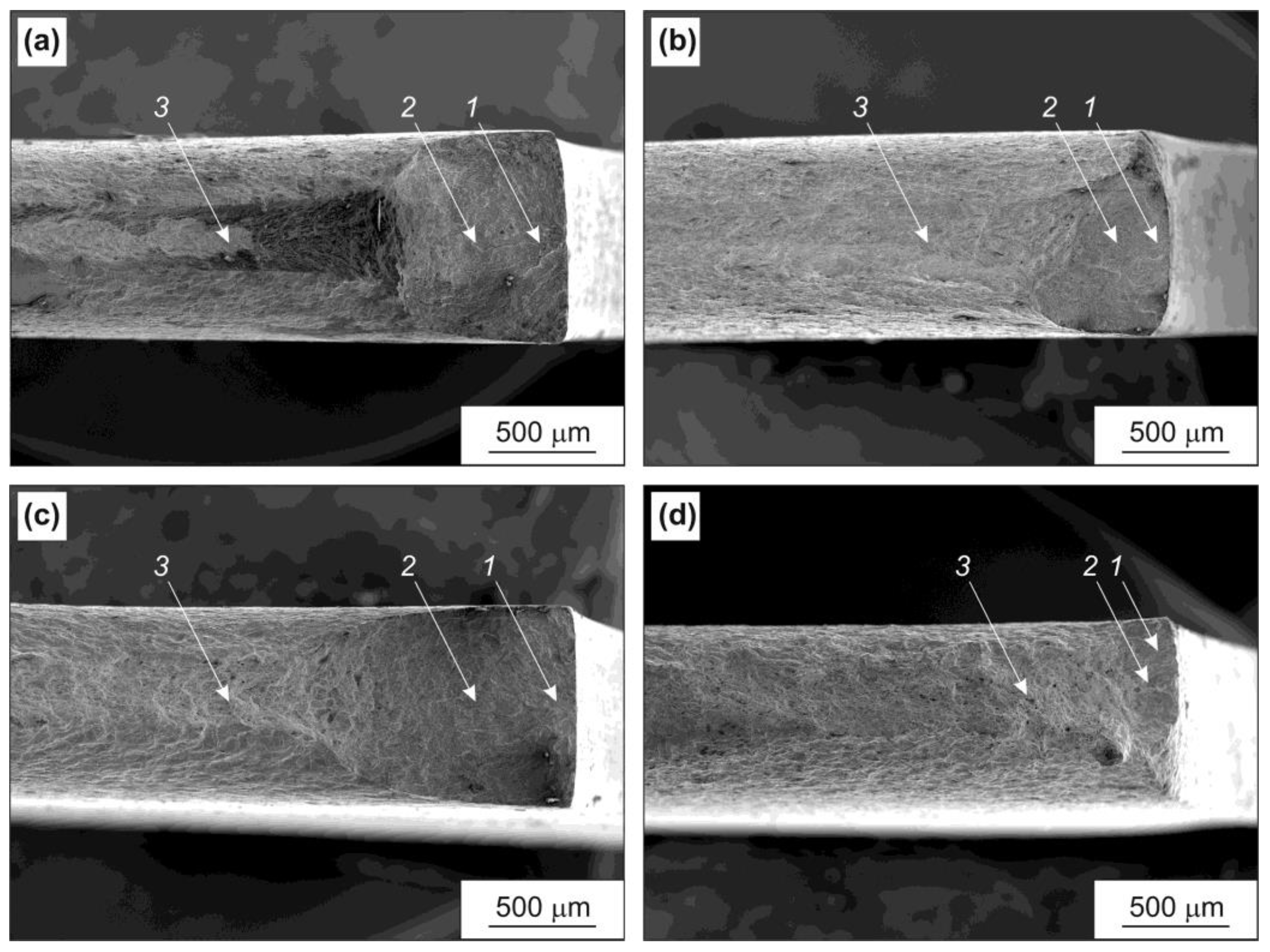
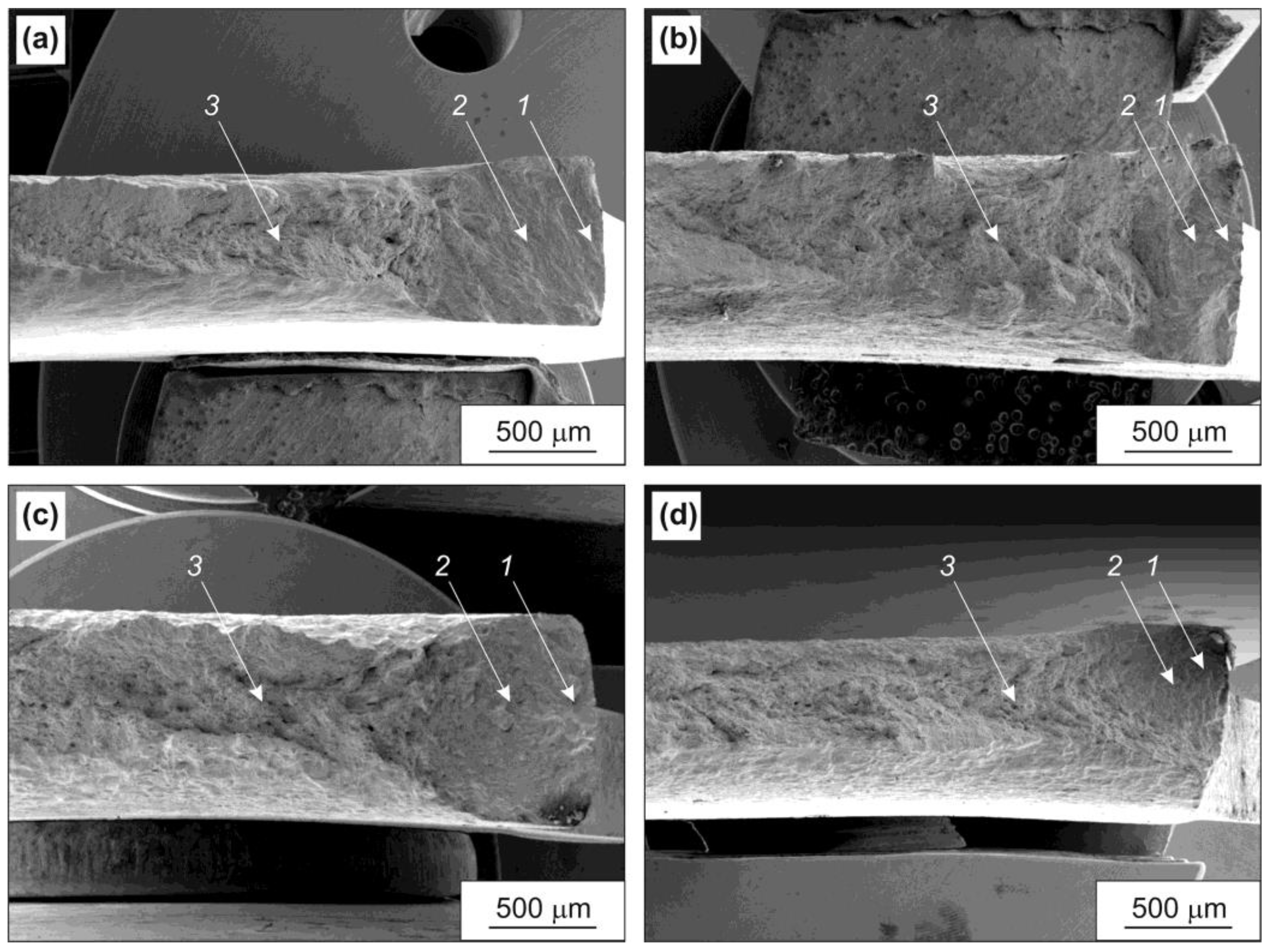
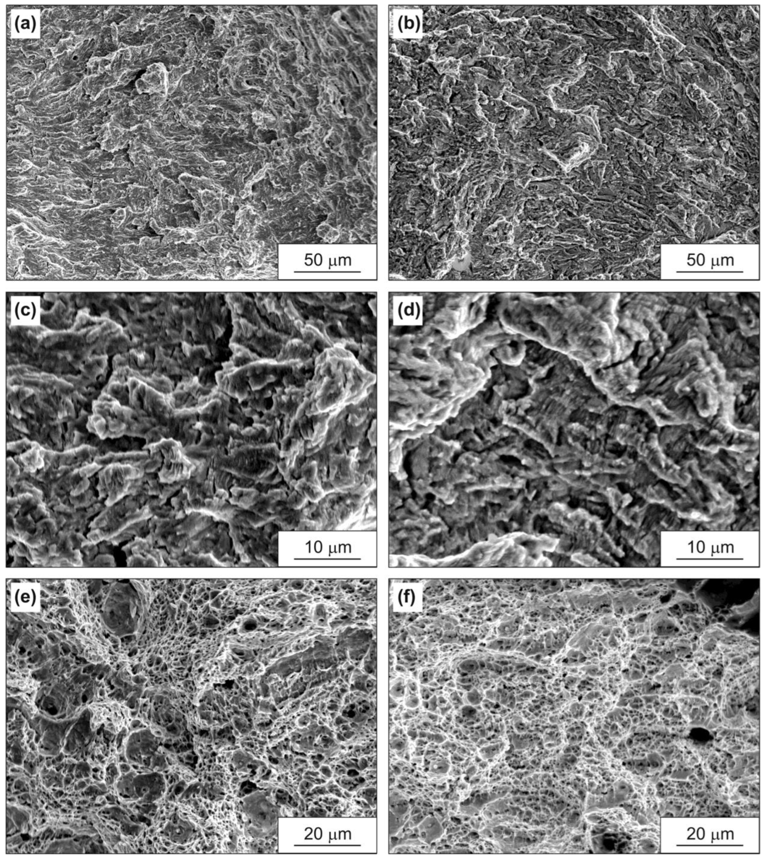
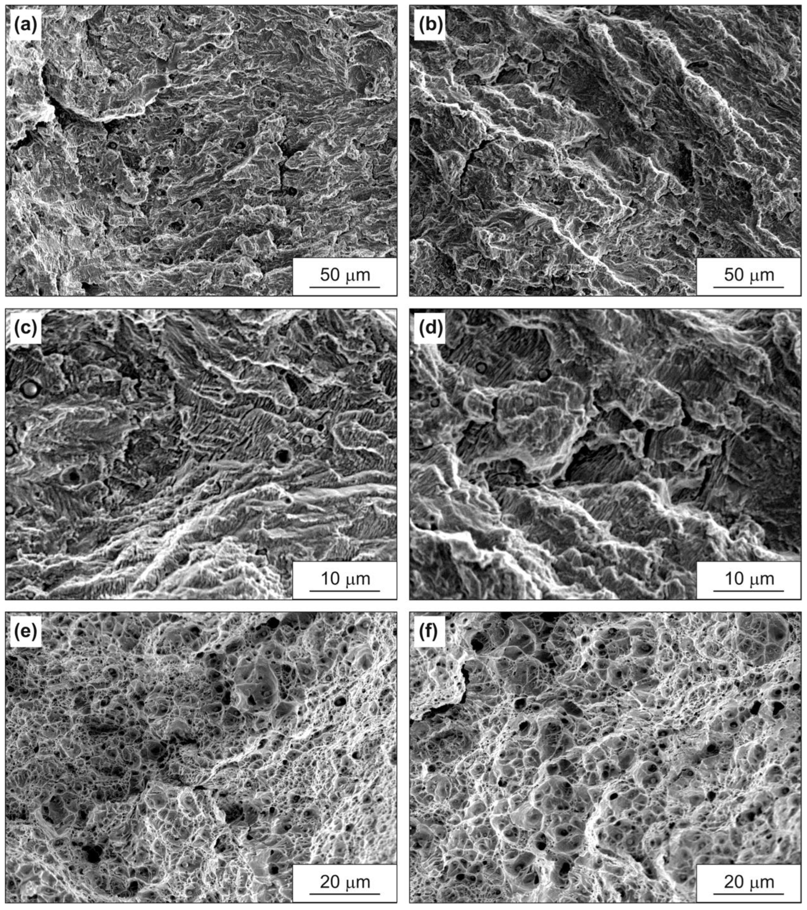
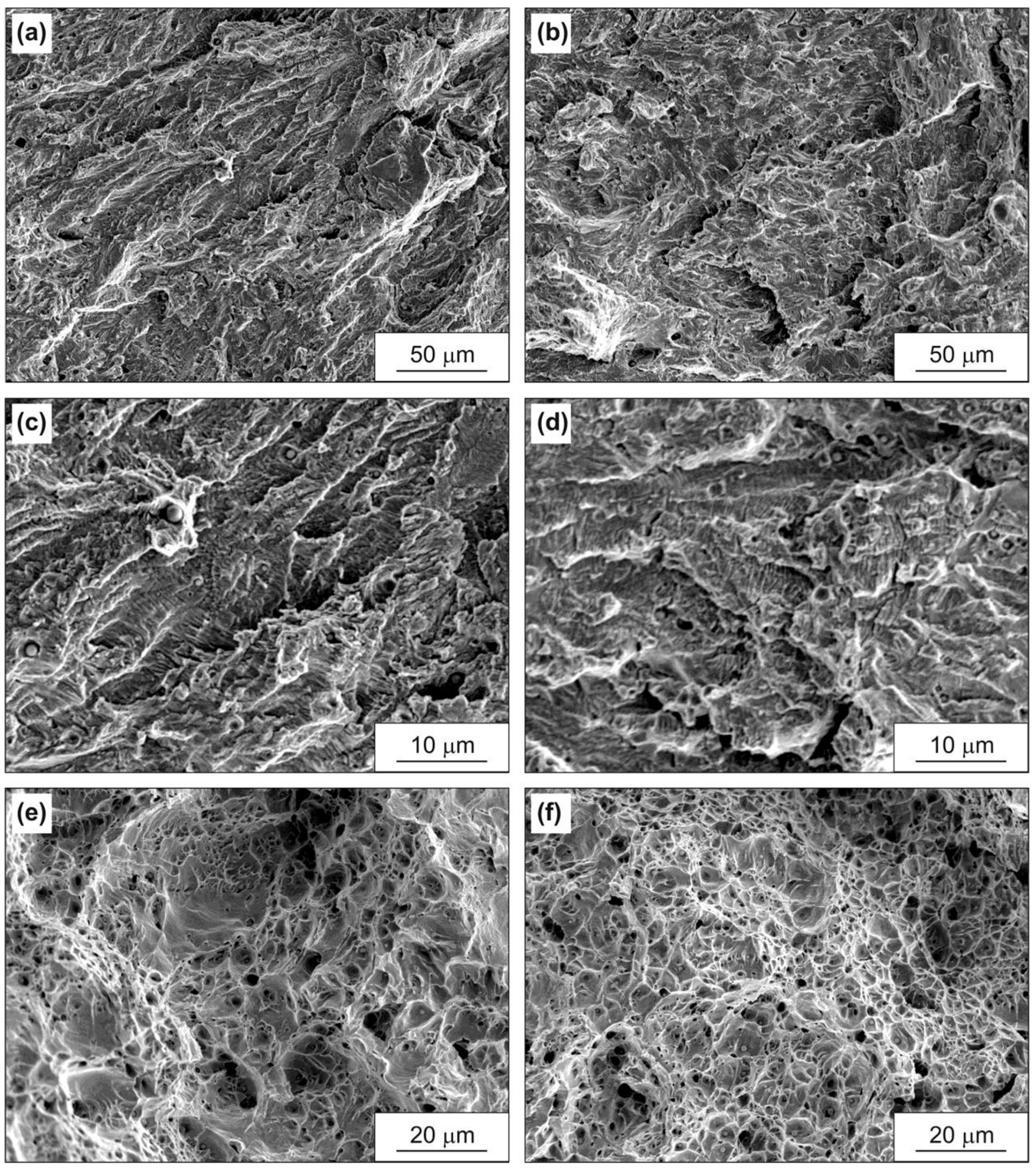
3.3. Fractographic Analysis
4. Discussion
5. Conclusions
- (1)
- The samples under all conditions had a high endurance limit, which was 70–90% of the ultimate strength. The highest endurance limit of the base metal samples as delivered was 475 MPa. The endurance limit of the weld metal samples as delivered was lower by 12%. Overheating led to a decrease in the endurance limit of the base metal samples by 19% and in the weld metal samples by 7%.
- (2)
- During fatigue testing, all samples showed cyclic hardening behavior.
- (3)
- The mechanism of fatigue fractures for all samples was quasi-brittle with the presence of very thin fatigue micro-grooves.
Author Contributions
Funding
Institutional Review Board Statement
Informed Consent Statement
Data Availability Statement
Conflicts of Interest
References
- DIN 17145-80; Round Wire Rod for Welding Filler Metals. Technical Conditions of Delivery; Beuth Publishing: Berlin, Germany, 1980.
- Budynas, R.G.; Nisbett, J.K. Shigley’s Mechanical Engineering Design, 9th ed.; McGraw-Hill: New York, NY, USA, 2011; pp. 49–52. [Google Scholar]
- Kuptsov, S.G.; Pleshchev, V.P.; Magomedova, R.S.; Nikonenko, E.A.; Shimov, V.V. Hybrid Hardening of Structural Steel, Grade 09G2S. Steel Transl. 2021, 51, 342–344. [Google Scholar] [CrossRef]
- Kryukov, R.E.; Gromov, V.E.; Ivanov, Y.F.; Kozyrev, N.A.; Rubannikova, Y.A. Fine Structure and Fracture Surface of Low-Carbon Steel Welds. Russ. Phys. J. 2021, 65, 332–336. [Google Scholar] [CrossRef]
- Saraev, Y.N.; Gladkovsky, S.V.; Lepikhin, S.V.; Dvoynikov, D.A.; Kamantsev, I.S.; Veselova, V.E. Influence of the welding method on the impact strength and cyclic fracture toughness parameters of the 09G2S steel. AIP Conf. Proc. 2017, 1915, 030024. [Google Scholar] [CrossRef]
- Vorontsov, A.V.; Utyaganova, V.R.; Chumaevskii, A.V.; Gurianov, D.A.; Ivanov, A.N. Structure and mechanical properties of laser-arc hybrid welding of 13Mn6 steel welded with austenitic filler. IOP Conf. Ser. Mater. Sci. Eng. 2019, 537, 022071. [Google Scholar] [CrossRef]
- Khadeev, G.E. Effect of Multistage Deformation during the Pipe Manufacturing on Mechanical Properties of Steels Strength Grade X70–X80. Key Eng. Mater. 2016, 716, 957–962. [Google Scholar] [CrossRef]
- Odesskii, P.D.; Egorova, A.A. Strength of steel for unique engineering structures. Russ. Metall. 2012, 2012, 911–918. [Google Scholar] [CrossRef]
- Nikulin, S.A.; Rogachev, S.O.; Belov, V.A.; Turilina, V.Y.; Shplis, N.V. Effect of High Temperatures on the Mechanical Properties of the Weld Metal in the Welded Joint of Low-Carbon Low-Alloy Steel. Russ. Metall. 2021, 2021, 1314–1319. [Google Scholar] [CrossRef]
- Fischer, M. The severe accident mitigation concept and the design measures for core melt retention of the European Pressurized Reactor (EPR). Nucl. Eng. Des. 2004, 230, 169–180. [Google Scholar] [CrossRef]
- Sultan, T.; Sapra, M.K.; Kundu, S.; Kadam, A.V.; Kulkarni, P.P.; Rao, A.R. Experimental & analytical study of passive thermal sensing system developed for cooling water injection into AHWR core catcher. Nucl. Eng. Des. 2017, 322, 81–91. [Google Scholar] [CrossRef]
- Chen, C.Y.; Huang, J.Y.; Yeh, J.J.; Hwang, J.R.; Huang, J.Y. Microstructural evaluation of fatigue damage in SA533-B1 and type 316L stainless steels. J. Mater. Sci. 2003, 38, 817–822. [Google Scholar] [CrossRef]
- Nikulin, S.A.; Rogachev, S.O.; Belov, V.A.; Komissarov, A.A.; Turilina, V.Y.; Shplis, N.V.; Nikolaev, Y.A. Impact strength of low-carbon steel 09G2S welded joint metal. Metallurgist 2022, 65, 1391–14009. [Google Scholar] [CrossRef]
- Kim, Y.; Hwang, W. High-Cycle, Low-Cycle, Extremely Low-Cycle Fatigue and Monotonic Fracture Behaviors of Low-Carbon Steel and Its Welded Joint. Materials 2019, 12, 4111. [Google Scholar] [CrossRef] [PubMed]
- Hasunuma, S.; Oki, S.; Motomatsu, K.; Ogawa, T. Fatigue life prediction of carbon steel with machined surface layer under low-cycle fatigue. Int. J. Fatigue 2019, 123, 255–267. [Google Scholar] [CrossRef]
- Huang, Z.Y.; Wagner, D.; Bathias, C.; Chaboche, J.L. Cumulative fatigue damage in low cycle fatigue and gigacycle fatigue for low carbon–manganese steel. Int. J. Fatigue 2011, 33, 115–121. [Google Scholar] [CrossRef]
- Zhou, Q.; Qian, L.; Meng, J.; Zhao, L.; Zhang, F. Low-cycle fatigue behavior and microstructural evolution in a low-carbon carbide-free bainitic steel. Mater. Des. 2015, 85, 487–496. [Google Scholar] [CrossRef]
- Rosado-Carrasco, J.G.; González-Zapatero, W.F.; García, C.J.; Gómora, C.M.; Jaramillo, D.; Ambriz, R.R. Analysis of the Low Cycle Fatigue Behavior of DP980 Steel Gas Metal ArcWelded Joints. Metals 2022, 12, 419. [Google Scholar] [CrossRef]
- Nip, K.H.; Gardner, L.; Davies, C.M.; Elghazouli, A.Y. Extremely low cycle fatigue tests on structural carbon steel and stainless steel. J. Constr. Steel. Res. 2010, 66, 96–110. [Google Scholar] [CrossRef]
- Zhang, M.; Yang, P.; Tan, Y. Micromechanisms of fatigue crack nucleation and short crack growth in a low carbon steel under low cycle impact fatigue loading. Int. J. Fatigue 1999, 21, 823–830. [Google Scholar] [CrossRef]
- Prosvirnin, D.V.; Kolmakov, A.G.; Larionov, M.D.; Pivovarchik, S.V. Peculiarities of deformation of thin-sheet TRIP steel under static and fatigue loading. J. Phys. Conf. Ser. 2021, 1758, 012042. [Google Scholar] [CrossRef]
- Plumbridge, W.J. Review: Fatigue-crack propagation in metallic and polymeric materials. J. Mater. Sci. 1972, 7, 939–962. [Google Scholar] [CrossRef]
- Masuda, C.; Ohta, A.; Nishijima, S.; Sasaki, E. Fatigue striation in a wide range of crack propagation rates up to 70 μm/cycle in a ductile structural steel. J. Mater. Sci. 1980, 15, 1663–1670. [Google Scholar] [CrossRef]
- Gjonaj, M.; Cukalla, M. High cycle fatigue of low alloy carbon steels. J. Mater. Process. Technol. 1997, 64, 141–148. [Google Scholar] [CrossRef]
- Botvina, L.R.; Petrova, I.M.; Gadolina, I.V.; Levin, V.P.; Demina, Y.A.; Soldatenkov, A.P.; T’utin, M.P. High-Cycle Fatigue Failure of Low-Carbon Steel after Long-Term Aging. Inorg. Mater. 2010, 46, 1570–1577. [Google Scholar] [CrossRef]
- He, J.-C.; Zhu, S.-P.; Luo, C.; Niu, X.; Wang, Q. Size effect in fatigue modelling of defective materials: Application of the calibrated weakest-link theory. Int. J. Fatigue. 2022, 165, 107213. [Google Scholar] [CrossRef]
- Liao, D.; Zhu, S.-P.; Keshtegar, B.; Qian, G.; Wang, Q. Probabilistic framework for fatigue life assessment of notched components under size effects. Int. J. Mech. Sci. 2020, 181, 105685. [Google Scholar] [CrossRef]
- GOST 25.502-79; Strength Analysis and Testing in Machine Building. Methods of Metals Mechanical Testing. Methods of Fatigue Testing. GostPerevod: Moscow, Russia, 1979.
- Pumpyanskiy, D.A.; Pyshmintcev, I.Y.; Maltseva, A.N.; Khatkevich, V.M.; Arsenkin, A.M. Strain Hardening of 09G2S Steel at Elevated Temperatures. Russ. Metall. 2021, 2021, 1128–1134. [Google Scholar] [CrossRef]
- Noh, K.; Shams, S.A.A.; Kim, W.; Kim, J.N.; Lee, C.S. Influence of Microstructure on Low-Cycle and Extremely-Low-Cycle Fatigue Resistance of Low-Carbon Steels. Met. Mater. Int. 2021, 27, 3862–3874. [Google Scholar] [CrossRef]
- Kim, Y.; Kwon, J.; Lee, H.; Jang, W.; Choi, J.; Kim, S. Effect of Microstructure on Fatigue Crack Propagation and S–N Fatigue Behaviors of TMCP Steels with Yield Strengths of Approximately 450 MPa. Metall. Mater. Trans. A 2011, 42, 986–999. [Google Scholar] [CrossRef]
- Heald, P.T.; Lindley, T.C.; Richards, C.E. The influence of stress intensity and microstructure on fatigue crack propagation in a 1% carbon steel. Mater. Sci. Eng. 1972, 10, 235–240. [Google Scholar] [CrossRef]


| Material | Fe | C | Si | Mn | P | S | Cr | Ni | Cu | Co |
|---|---|---|---|---|---|---|---|---|---|---|
| Base metal | Bal. | 0.10 | 0.67 | 1.54 | 0.012 | 0.005 | 0.07 | 0.12 | 0.15 | 0.02 |
| Weld metal | Bal. | 0.09 | 0.61 | 1.49 | 0.012 | 0.005 | 0.04 | 0.07 | 0.10 | 0.01 |
| 13Mn6 | Bal. | <0.12 | 0.5–0.8 | 1.3–1.7 | <0.03 | <0.04 | <0.3 | <0.3 | <0.3 | - |
| Material, Processing | Yield Strength, MPa | Tensile Strength, MPa | Elongation, % | Endurance Limit, MPa | Ratio of Endurance Limit to Tensile Strength |
|---|---|---|---|---|---|
| Base metal, as delivered | 430 ± 15 | 556 ± 12 | 28 ± 2 | 475 | 0.9 |
| Weld metal, as delivered | 377 ± 23 | 507 ± 21 | 30 ± 3 | 420 | 0.8 |
| Base metal, overheated | 319 ± 7 | 511 ± 7 | 35 ± 2 | 385 | 0.7 |
| Weld metal, overheated | 305 ± 14 | 461 ± 6 | 43 ± 2 | 390 | 0.8 |
Disclaimer/Publisher’s Note: The statements, opinions and data contained in all publications are solely those of the individual author(s) and contributor(s) and not of MDPI and/or the editor(s). MDPI and/or the editor(s) disclaim responsibility for any injury to people or property resulting from any ideas, methods, instructions or products referred to in the content. |
© 2023 by the authors. Licensee MDPI, Basel, Switzerland. This article is an open access article distributed under the terms and conditions of the Creative Commons Attribution (CC BY) license (https://creativecommons.org/licenses/by/4.0/).
Share and Cite
Nikulin, S.A.; Rogachev, S.O.; Prosvirnin, D.V.; Pivovarchik, S.V.; Belov, V.A.; Shplis, N.V.; Zadorozhnyy, M.Y.; Khatkevich, V.M. Influence of Overheating on High-Cycle Fatigue Characteristics of the Base Metal and Weld Metal of Low-Carbon Steel Welded Joints. Metals 2023, 13, 1707. https://doi.org/10.3390/met13101707
Nikulin SA, Rogachev SO, Prosvirnin DV, Pivovarchik SV, Belov VA, Shplis NV, Zadorozhnyy MY, Khatkevich VM. Influence of Overheating on High-Cycle Fatigue Characteristics of the Base Metal and Weld Metal of Low-Carbon Steel Welded Joints. Metals. 2023; 13(10):1707. https://doi.org/10.3390/met13101707
Chicago/Turabian StyleNikulin, Sergey A., Stanislav O. Rogachev, Dmitriy V. Prosvirnin, Svetlana V. Pivovarchik, Vladislav A. Belov, Nikolay V. Shplis, Mikhail Y. Zadorozhnyy, and Vladimir M. Khatkevich. 2023. "Influence of Overheating on High-Cycle Fatigue Characteristics of the Base Metal and Weld Metal of Low-Carbon Steel Welded Joints" Metals 13, no. 10: 1707. https://doi.org/10.3390/met13101707
APA StyleNikulin, S. A., Rogachev, S. O., Prosvirnin, D. V., Pivovarchik, S. V., Belov, V. A., Shplis, N. V., Zadorozhnyy, M. Y., & Khatkevich, V. M. (2023). Influence of Overheating on High-Cycle Fatigue Characteristics of the Base Metal and Weld Metal of Low-Carbon Steel Welded Joints. Metals, 13(10), 1707. https://doi.org/10.3390/met13101707