Abstract
The orthotropic steel deck is sensitive to fatigue, and a number of cracks have been found in existing bridges. Based on the long-span Guangzhou Mingzhu Bay steel arched bridge, this paper focus on the cracking process, fatigue mechanism, and fatigue performance evaluation of an orthotropic steel bridge deck under traffic load. A finite element model of a three-U-rib and three-span bridge deck was first established to investigate the stress state and the most unfavorable wheel loading position under the longitudinal wheel load. Then, four full-scale single-U-rib specimens were fabricated with high-strength lower alloy structural steel Q370qD in compliance with construction standards. High-cycle loading was subsequently implemented according to the Specification for Design of Highway steel bridge (JTG D64-2015), and the crack initiation, propagation process, and fatigue failure modes were studied. The results showed the stress at structural concern points is larger than in other locations, which was located around 35 mm from the welding seam of the U-rib and the lower end of the diaphragm plate. The Mingzhu Bay steel bridge deck meets the fatigue design requirements. However, the bottom of the welding seam between the U-rib and diaphragm plate is a dangerous fatigue position, and attention should be paid to the welding quality at this position during construction.
1. Introduction
Orthotropic steel decks (OSD) are composed of orthotopically deck plates stiffened by longitudinal ribs and transverse diaphragms, which are widely used in various types of large- and medium-sized long-span steel bridges due to the benefits of a high bearing capacity, light weight, and short construction period [1,2,3,4,5,6]. In the past decades, this type of steel deck has been improved in terms of design, fabrication, and maintenance, and the structural behavior has been enhanced. However, as the orthotropic steel decks withstand high-level cycles of traffic load, fatigue cracks may occur at the weld connection or other points of stress concentration points, which will seriously affect traffic safety [7,8,9,10].
In a literature review, it was found that many studies have been conducted on fatigue performance assessment and prediction models [11,12,13,14,15,16]. These models were generally based on fracture mechanics and cumulative damage theories. For example, Wu et al. [17] considered the influence of the crack closure effect on metals’ mechanical properties and established a mathematical model for fatigue life prediction based on the law of metal fatigue characteristics. Macek et al. [18] proposed a mixed-mechanics measurement method to determine the three-dimensional port damage of specimens with fatigue bending loading history. Furthermore, the fatigue performance evaluation methods of a steel bridge deck mainly include the nominal stress method, hot spot stress method, and notch stress method [19,20,21,22,23]. The nominal stress method is convenient for calculation and engineering applications, which are widely adopted in bridge specifications [24,25,26,27].
Since the design, fabrication, and construction details of orthotropic steel decks are varied from the bridge, the fatigue performance analysis of bridges is generally based on the specific bridge [28]. Many efforts have been made to investigate the fatigue performance of orthotropic steel decks. Zeng et al. [29] conducted 1:2 scale fatigue experiments on the orthotropic steel bridge panel; the design life cycle loading was applied. It was concluded that the bridge met the design requirements and had a certain safety reserve during the service. Huang et al. [30] carried out fatigue tests and theoretical studies on the steel bridge deck of the Yangtze River Bridge under heavy traffic loads to evaluate the fatigue life. The results showed that the initial crack depth was sensitive to fatigue life evaluation. Deck plates, U-ribs, and transverse diaphragms are the load-bearing components and are the main sources of bridge deck stiffness and stability. However, the joints of longitudinal ribs, the deck plate, the transverse diaphragm, and the structural details of the transverse diaphragm are prone to fatigue cracking [31]. Cao et al. [32] analyzed the fatigue performance of the Jiangyin Yangtze River Bridge, the finite element model was established, and the influence of residual welding stress and vehicle load stress on the fatigue performance of the bridge deck was studied. The results showed that the steel deck thickness is relevant to the fatigue life of orthotropic steel decks. At the same time, Zhong et al. [33] analyzed the fatigue life of the Jiangyin Yangtze River Bridge. A coupling stress analysis FE model was established that considered the residual welding stress and vehicle load. The results showed that the residual tensile stress at the weld position was superimposed on the cyclic tensile stress of the main vehicle load, and the longitudinal stress relaxation exceeded the peak vehicle load stress. Ji et al. [34] employed traffic monitoring data to establish a load model to evaluate the root-deck fatigue durability of the Taizhou Bridge. Cheng et al. [35] analyzed the FE model of the Balinghe Bridge under traffic load, and the results showed that fatigue cracks initiated at the arc opening and extended to the welded seam of the diaphragm plate. A health detection plan was proposed. Yang et al. [36] established the finite element model of the Taizhou Yangtze River Bridge. The stress amplitude and fatigue damage of the steel bridge deck were studied. The stress state of the diaphragm under the lateral distribution of wheel load was obtained. It was shown that the stress amplitude of the diaphragm increased with the increase in the diaphragm spacing. Zeng et al. [37] established a 1:2 scale experiment of an orthotropic steel bridge deck under fatigue loading; it was found that with good welding quality and standard maintenance, the orthotropic steel bridge deck would not develop fatigue cracks during its life service.
Although scholars have completed a lot of studies on the fatigue properties of metal materials and orthotropic steel bridge decks, due to the differences in materials, designs, and construction details, it is still necessary to conduct numerical and experimental studies on the fatigue performance of specific long-span steel bridge decks in order to ensure safety during their service. Therefore, this study is based on the Mingzhu Bay steel truss arched bridge. A finite element model of a bridge deck was first established to investigate the stress state and the most unfavorable loading position. Four single U-rib specimens were used to investigate the crack initiation, propagation process, and fatigue failure modes. Finally, the fatigue performance of the steel deck was evaluated according to the specifications. Figure 1 shows the flow chart of this paper.
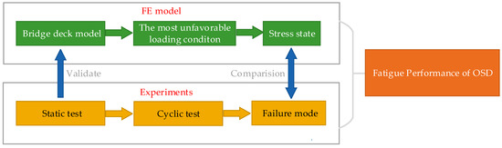
Figure 1.
Flow chart.
2. Project Summary
The Mingzhu Bay Bridge main bridge adopts (96 + 164 + 436 + 164 + 96 + 60) m = 1016 m span continuous steel truss bridge [38]. The main span of the main bridge is three arched truss structures; the truss spacing is 18.1 m, the side truss height is 10.369 m, the middle truss height is 10.685 m, and the side span and the second side span are flat truss structures. The side span and the main arch rib are “N”-type trusses. The layout of the Mingzhu Bay Bridge is shown in Figure 2.
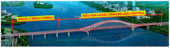
Figure 2.
General layout of Guangzhou Mingzhu Bay Bridge.
The steel deck of the Mingzhu bay Bridge adopts a double-deck arrangement, as illustrated in Figure 3. The upper deck is a two-way, eight-lane highway with sidewalks on both sides. The total width of the main bridge deck is 43.2 m. An orthotropic steel deck with a thickness of 16 mm and a u-shaped closed rib with a spacing of 600 mm are adopted. A diaphragm is provided every 3 m longitudinally and bolted with the upper chord.
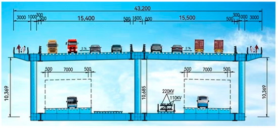
Figure 3.
Deck arrangement (unit: mm).
3. Finite Element Model
3.1. Materials
A finite element model of the 3 spans and 3 U-ribs was established using Abaqus software (2016, Dassault SIMULIA, Paris, France). The FE model was 9 m long from the longitudinal direction and 1.5 m wide from the transverse direction. Solid element C3D8 was employed. The elastic modulus of the plate was 206 GPa, and the Poisson’s ratio was 0.3. The fixed constraint was applied at the bottom of the diaphragm plate. The steel deck of Mingzhu Bay Bridge is made of Q370qD. The chemical composition and mechanical properties are shown in Table 1 and Table 2.

Table 1.
The chemical composition of Q370qD (%) [39].
Table 2.
The mechanical properties of Q370qD.
3.2. Loading
To investigate the stress state and the most unfavorable wheel loading position, three loading conditions were considered, and the stress state of the bridge deck was analyzed. The details were as follows: (1) from the transverse direction, three wheel-loading positions were across the U-ribs, on the U-ribs, and between the U-ribs; (2) from the longitudinal direction, two loading positions were on middle span and OSD diaphragm. The details are shown in Figure 4.
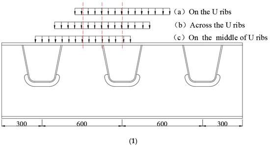
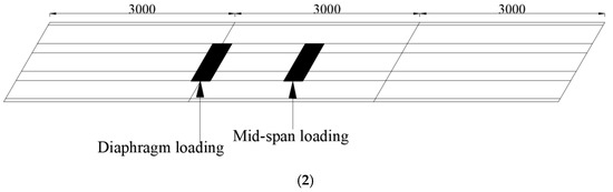
Figure 4.
Wheel loading positions. (1) Wheel load in the transverse direction (unit: mm); (2) wheel load in the longitudinal direction (unit: mm).
The vehicle load index was obtained from specification (JTG D64-2015) [25]. The pavement layer was 55 mm, and taking the projected area from angle of 45°, the wheel loading area is (7.1 × 3.1) m2, and the single wheel load is 120 kN. Hence, a single wheel’s loading pressure on the bridge deck is 0.2726 GPa.
3.3. FE Analysis
The results of FE model under mid-span and diaphragm wheel loading are shown in Figure 5. It was observed that the maximum stress points were always located at the welding joint of the U-ribs and transverse diaphragm. Since this area is prone to fatigue cracks under cyclic load, this location is taken as the area of concern.
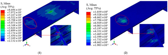
Figure 5.
Stress state of the bridge deck (unit: MPa). (1) Mid-span loading; (2) diaphragm loading.
The stress state results of FE model are listed in Table 3.
Table 3.
Stress results of FE model.
Using stress-state data in the Table 3, we can see that the maximum stress is 104.6 MPa, while the most unfavorable wheel loading position was on the U-ribs of mid-span loading.
4. Fatigue Tests
4.1. Specimen Design
Based on the FE analysis, a single U-rib was selected for the fatigue specimen, and the loading was on the U-rib. The fatigue specimen design was fabricated according to the design of the Mingzhu Bay bridge; the height and length were 560 mm and 600 mm, respectively. The thickness of the bridge deck was 16 mm; the welded seam was 8 mm in width. An extra steel pad and stiffener were welded to the bottom to maintain the stability of the loading. The steel grade was Q370qD, and the welding wire and process were the same as the Mingzhu Bay Bridge. The dimension details are shown in Figure 6.
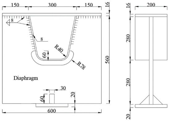
Figure 6.
Schematic diagram of specimen (unit: mm).
4.2. Static Loading
The objective of static loading was to validate the FE model, which was a three-span, three-U-rib OSD structure. Since the fatigue wheel load was in the elastic range, the static loading and unloading procedure involved 50 kN increments to 350 kN and decreases to 50 kN. The strain gauges were distributed at the concerning points. The strain gauge arrangement is shown in Figure 7.
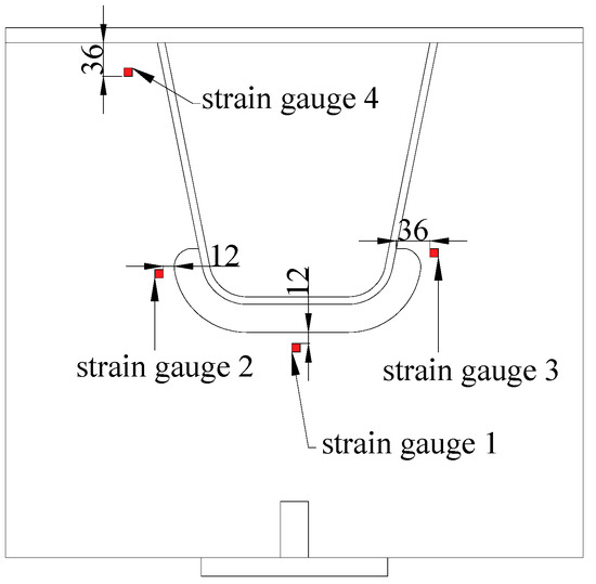
Figure 7.
Strain gauge arrangement.
The strain was converted, and the comparisons between tests and the FE model are shown in Figure 8.
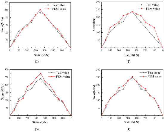
Figure 8.
Stress comparison between test and FE model. (1) Strain gauge 1; (2) strain gauge 2; (3) strain gauge 3; (4) strain gauge 4.
It can be seen from the Figure 8 that the stress state and distribution between the FE model show great agreement with the test data.
4.3. Fatigue Loading
An MTS hydraulic fatigue test machine (Mechanical Testing & Simulation, Eden, MN, USA) was used for the fatigue test loading, as shown in Figure 9. The cyclic load was 120 kN with an amplitude of 80 kN and 100 kN, and the cyclic frequency was 5 Hz.
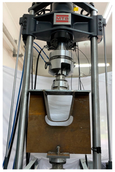
Figure 9.
Fatigue loading of specimens.
Table 4.
Fatigue test results.
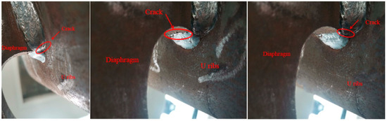
Figure 10.
Failure mode of specimens.
5. Fatigue Performance and Discussion
The fatigue performance of OSD is dependent on a variety of different parameters, such as the steel grade, welding quality, traffic load conditions, and design. It has been generally accepted that stress amplitudes under certain values, and the fatigue life could be treated as infinite. A high stress state or concentration increases the potential of fatigue cracks. Hence, the fatigue cracks were usually found at a higher stress state position around welding seams in the real construction. In other words, a higher stress state under the most unfavorable wheel load condition should receive more attention. For the FE model of the steel deck, the stress was extracted from A to B, as shown in Figure 11a. Stress values at toe 1, toe 2, and the welding root are shown in Figure 11b.
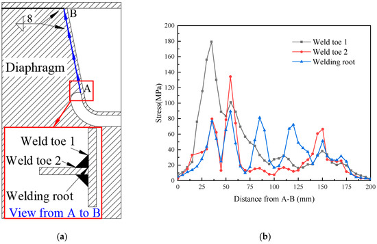
Figure 11.
Area of concern and welded seam stress. (a) Schematic diagram of welded seams; (b) seam stress.
From A to B, the stress of the welding seam decreased gradually, and the stress at toe 1 and toe 2 was 180 MPa and 130 MPa, which was located 35 mm and 55 mm at the lower end of the U-rib and diaphragm. The stress of the welding root was around 80 MPa and was distributed evenly from A to B, which indicates that the potential fatigue crack area was at weld toe 1 35–55 mm from the arc cut-out location.
As seen in the experiment’s phenomena, fatigue cracks also occurred at the welding seam between the U-rib and diaphragm, which were around the arc cut-out area of OSD. The fatigue cycles of all specimens were over two million in number and met the specification requirement.
6. Conclusions
In this paper, based on the Mingzhu Bay steel arch bridge, the fatigue performance of an orthotropic steel deck was studied through numerical and experimental analysis. The following conclusions were obtained: the fatigue crack was initialed at the point of concern, which was located 35–55 mm from the welding position at the lower end of the U-rib and diaphragm and then expanded along the weld to both sides. The crack was about 2 mm wide and 20 mm long at three million load cycles. The fatigue cycles of the specimens exceeded two million in number and satisfied the Specification for Design of Highway Steel Bridge (JTG D64-2015). The bridge deck of the Mingzhu Bay Bridge meets the fatigue requirements, but the welding seam of the U-rib and diaphragm is in a dangerous location of fatigue, so attention should be paid to the welding quality. The limitations of this paper are that the number of tests was inadequate, and the conclusions were based on the most unfavorable scenario.
Author Contributions
P.L., Y.C. and H.L. wrote the manuscript together, J.Z. and L.A. conducted data processing and drawings, Y.W. and J.L. revised the manuscript. All authors have read and agreed to the published version of the manuscript.
Funding
Funding was received from the Science and Technology Research and Development Project of China Railway Construction Bridge Engineering Bureau Group Co., Ltd. (DQJ-2018-A01); the Tianjin Science and Technology Development Plan Project (19YDLZSF00030); the National Natural Science Foundation of China (51038006).
Data Availability Statement
The data presented in this study are available on request from the corresponding author.
Acknowledgments
The author would like to thank the China Railway Construction and Bridge Bureau Group Co., Ltd. for the experiment support.
Conflicts of Interest
The authors declare no conflict of interest.
Nomenclature
—Welded seam, unit: mm. Weld toe—the junction of weld surface and base metal. Weld root—the junction between the back of the weld and the base metal
References
- Huang, Y.; Zhang, Q.; Bao, Y.; Bu, Y. Fatigue assessment of longitudinal rib-to-crossbeam welded joints in orthotropic steel bridge decks. J. Constr. Steel Res. 2019, 159, 53–66. [Google Scholar] [CrossRef]
- Fisher, J.W.; Barsom, J.M. Evaluation of cracking in the rib-to-deck welds of the Bronx Whitestone Bridge. J. Bridge Eng. 2015, 21, 4015065. [Google Scholar] [CrossRef]
- Dung, C.V.; Sasaki, E.; Tajima, K.; Suzuki, T. Investigations on the effect of Weld Penetration on Fatigue Strength of Rib-to-Deck Welded Joints in Orthotropic Steel Decks. Int. J. Steel Struct. 2015, 15, 299–310. [Google Scholar] [CrossRef]
- Kainuma, S.; Jeong, Y.S.; Yang, M.; Inokuchi, S. Welding residual stress in roots between deck plate and U-rib in orthotropic steel decks. Measurement 2016, 92, 475–482. [Google Scholar] [CrossRef]
- Connor, R.; Fisher, J.; Gatti, W.; Gopalartnam, V.; Kozy, B. Manual for Design, Construction, and Maintenance of Orthotropic Steel Deck Bridges; Federal Highway Administion, U.S. Department of Transportation: Washington, DC, USA, 2012. [Google Scholar]
- Liao, P.; Qu, B.; Huang, Y.L.; Jia, Y.; Wang, Y.B.; Zhu, H.F. Fatigue Life Assessment of Revised Cope-Hole Details in Steel Truss Bridges. Metals 2020, 9, 1092. [Google Scholar] [CrossRef]
- Gou, H.; Shi, X.; Zhou, W.; Cui, K.; Pu, Q. Dynamic performance of continuous railway bridges: Numerical analyses and field tests. Proc. Inst. Mech. Eng. Part F J. Rail Rapid Transit 2018, 232, 936–955. [Google Scholar] [CrossRef]
- Li, M.; Suzuki, Y.; Hashimoto, K.; Sugiura, K. Experimental study on fatigue resistance of rib-to-deck joint in orthotropic steel bridge deck. J. Bridge Eng. 2017, 23, 157–167. [Google Scholar] [CrossRef]
- Hobbacher, A. Recommendations for Fatigue Design of Welded Joints and Components, 2nd ed.; IIW Doc. IIW 2259-15; Springer: Berlin/Heidelberg, Germany, 2016. [Google Scholar]
- Chen, Y.X.; Lv, P.M.; Li, D.T. Research on Fatigue Strength for Weld Structure Details of Deck with U-rib and Diaphragm inOrthotropic Steel Bridge Deck. Metals 2019, 9, 484. [Google Scholar] [CrossRef] [Green Version]
- Pineau, A.; Antolovich, S.D. High temperature fatigue of nickel-base superalloys–A review with special emphasis on deformation modes and oxidation. Eng. Fail. Anal. 2009, 16, 2668–2697. [Google Scholar] [CrossRef]
- Yan, X.L.; Zhang, X.C.; Tu, S.T.; Mannan, S.L.; Xuan, F.Z.; Lin, Y.C. Review of creep–fatigue endurance and life prediction of 316 stainless steels. Int. J. Press. Vessel. Pip. 2015, 126–127, 17–28. [Google Scholar] [CrossRef]
- Santecchia, E.; Hamouda, A.M.S.; Musharavati, F.; Zalnezhad, E.; Cabibbo, M.; El Mehtedi, M.; Spigarelli, S. A Review on Fatigue Life Prediction Methods for Metals. Adv. Mater. Sci. Eng. 2016, 2016, 9573524. [Google Scholar] [CrossRef] [Green Version]
- Kamal, M.; Rahman, M.M. Advances in fatigue life modeling: A review. Renew. Sustain. Energy Rev. 2018, 82, 940–949. [Google Scholar] [CrossRef]
- Cao, Y.; Nie, W.; Yu, J.; Tanaka, K. A Novel Method for Failure Analysis Based on Three-dimensional Analysis of Fracture Surfaces. Eng. Fail. Anal. 2014, 44, 74–84. [Google Scholar] [CrossRef]
- Wang, X.W.; Zhang, W.; Zhang, T.Y.; Gong, J.M.; Abdel Wahab, M. A New Empirical Life Prediction Model for 9–12% Cr Steels under Low Cycle Fatigue and Creep Fatigue Interaction Loadings. Metals 2019, 9, 183. [Google Scholar] [CrossRef] [Green Version]
- Wu, Q.; Liu, X.T.; Liang, Z.Q.; Wang, Y.S.; Wang, X.L. Fatigue life prediction model of metallic materials considering crack propagation and closure effect. J. Braz. Soc. Mech. Sci. Eng. 2020, 42, 424. [Google Scholar] [CrossRef]
- Maceka, W.; Owsińskib, R.; Trembaczc, J.; Brancod, R. Three-dimensional fractographic analysis of total fracture areas in 6082 aluminium alloy specimens under fatigue bending with controlled damage degree. Mech. Mater. 2020, 147, 103410. [Google Scholar] [CrossRef]
- Ye, X.W.; Su, Y.H.; Han, J.P. A State-of-the-Art Review on Fatigue Life Assessment of Steel Bridge. Math. Probl. Eng. 2014, 2014, 956473. [Google Scholar] [CrossRef] [Green Version]
- Xiao, Z.G.; Yamada, K.; Ya, S.; Zhao, X.L. Stress analyses and fatigue evaluation of rib-to-deck joints in steel orthotropic deck. Int. J. Fatigue 2008, 30, 1387–1397. [Google Scholar] [CrossRef]
- BS 5400; Part 10: Code of Practice for Fatigue. British Stangard Institution: London, UK, 1980.
- AASHTO LRFD Bridge Design Specifications; American Association of State and Transportation Officials: Washington, DC, USA, 2007.
- Marques, J.M.; Benasciutti, D.; Niesłony, A.; Slavič, J. An Overview of Fatigue T esting Systems for Metals under Uniaxial and Multiaxial Random Loadings. Metals 2021, 11, 447. [Google Scholar] [CrossRef]
- ENV 1991-2-6:1997; Eurocode 1. Basis of Design and Actions on Structures. European Committee for Stangardization: Brussels, Belgium, 1997.
- JTG D64-2015; Code for Design of Highway Steel Structure Bridges. National Standards of the People’s Republic of China: Beijing, China, 2015.
- Wang, Z.; Wang, Y. Fatigue crack propagation law of orthotropic steel bridge deck. J. Cent. South Univ. 2020, 51, 1873–1882. (In Chinese) [Google Scholar] [CrossRef]
- Li, J.; Zhang, Q.; Bao, Y.; Zhu, J.; Chen, L.; Bu, Y. An equivalent Structural stress-based fatigue evaluation framework for rib-to-deck welded joints in orthotropic steel deck. Eng. Struct. 2019, 196, 109304. [Google Scholar] [CrossRef]
- Wang, Q.; Ji, B.; Li, C.; Fu, Z. Fatigue evaluation of rib-deck welds: Crack-propagation-life predictive model and parametric analysis. J. Constr. Steel Res. 2020, 173, 106248. [Google Scholar] [CrossRef]
- Huang, Y.; Zhang, Q.H.; Guo, Y.W.; Bu, Y.Z. Study on welding Detail Surface Defects and Fatigue effect of longitudinal Rib and Diaphragm plate of steel Bridge Deck. Eng. Mech. 2019, 36, 203–223. (In Chinese) [Google Scholar] [CrossRef]
- Lv, P.M.; Wang, L.F.; Li, D.T.; Lei, J.; Zhang, X.L. Fatigue behavior of u-rib and diaphragm plate of orthotropic steel bridge deck. J. Chang. Univ. Nat. Sci. Ed. 2015, 35, 63–70. (In Chinese) [Google Scholar] [CrossRef]
- Cao, B.Y.; Ding, Y.L.; Song, Y.S.; Zhong, W. Fatigue Life Evaluation for Deck-Rib Welding Details of Orthotropic Steel Deck Integrating Mean Stress Effects. J. Bridge Eng. 2019, 24, 04018114. [Google Scholar] [CrossRef]
- Zhong, W.; Ding, Y.L.; Song, Y.S.; Geng, F.F. Relaxation Behavior of Residual Stress on Deck-to-Rib welded Joints by Fatigue Loading in an Orthotropic Bridge Deck. Period. Polytech.-Civ. Eng. 2020, 63, 1125–1138. [Google Scholar] [CrossRef]
- Ji, B.; Liu, R.; Chen, C.; Maeno, H.; Chen, X. Evaluation on root-deck fatigue of orthotropic steel bridge deck. J. Constr. Steel Res. 2013, 90, 174–183. [Google Scholar] [CrossRef]
- Cheng, J.H.; Xiong, J.M.; Zhou, J.Z. Finite Element Anaiysis on mechanical behavior of orthotropic steel bridge deck in Balinghe Bridge. Adv. Mater. Res. 2013, 639–640, 239–242. [Google Scholar] [CrossRef]
- Yang, M.Y.; Liu, R.; Ji, B.H.; Xu, H.J.; Chen, C.; Zhao, D.D. Fatigue Stress Analysis of Disphragm Cap Hole in Orthotropic Steel Bridge Decks. Appl. Mech. Mater. 2012, 204–208, 3265–3269. [Google Scholar] [CrossRef]
- Zeng, Y.; Tan, H.; Zhong, H.; Yu, Q. Experimental study of fatigue properties of orthotropic steel deck with U-shaped stiffeners. Proc. Inst. Civ. Eng.-Struct. Build. 2020, 173, 128–140. [Google Scholar] [CrossRef]
- Liu, G.; Liu, Y.; Huang, Y. A novel structural stress approach for multiaxial fatigue strength assessment of welded joints. Int. J. Fatigue 2014, 63, 171–182. [Google Scholar] [CrossRef]
- Hu, H.Y.; Zhao, J.; Ren, Y.L.; An, L.M.; Liu, Y.T. Overall design of main bridge of guangzhou mingzhu bay bridge. Bridge Constr. 2021, 51, 93–99. (In Chinese) [Google Scholar] [CrossRef]
- GB/T 714-2015; Structural Steel for Bridges. National Standard of the People’s Republic of China: Beijing, China, 2015.
Publisher’s Note: MDPI stays neutral with regard to jurisdictional claims in published maps and institutional affiliations. |
© 2022 by the authors. Licensee MDPI, Basel, Switzerland. This article is an open access article distributed under the terms and conditions of the Creative Commons Attribution (CC BY) license (https://creativecommons.org/licenses/by/4.0/).