Abstract
In slab continuous-casting machines, the quality of the finished product mainly depends on the hydrodynamic behavior of the molten steel in the cavity of the continuous-casting mold, where the submerged entry nozzle is the central element. Recently, a nontraditional nozzle design was reported, where a solid barrier attached to the inner bottom wall of the nozzle divides its internal volume, particularly around the outlet ports. The solid barrier was named a flow divider. In this work, the effect of the flow divider is analyzed by comparing the performance of traditional nozzles with the performance of nozzles altered with the flow divider. The performance of the nozzles was evaluated experimentally, employing a scaled model of the mold section, using cold water as the working fluid. The shape of the nozzle outlet jets and the fluid flow pattern in the mold cavity were used to determine the performance of the nozzles. In addition, several factors affecting the process stability and the quality of the product were analyzed: the casting speed, the tilt of the nozzle outlet ports, and the injection of gas in the liquid stream entering the nozzle. The analysis showed that for the nozzles with the flow divider, (i) the outlet jets are narrow and symmetric, (ii) the symmetrical double-roll flow pattern in the mold cavity is obtained, (iii) the liquid-free surface is stable and has low distortions, and (iv) the flow divider neither increases the bubble breakage nor the coalescence between them.
1. Introduction
Several configurations have been tested for the nozzle that delivers the molten steel from the tundish into the mold of a slab continuous-casting machine [1,2]. Three variants of traditional bifurcated submerged entry nozzles (SEN) are shown in Figure 1a–c, which share the following features. First, the external shape is cylindrical-like; however, the body could also be an elongated squared prism with rounded edges. Second, the shape of the nozzle bore is cylindrical with smooth walls; nonetheless, nozzles with nonsmooth walls on the bore have also been studied [2]. Third, standard slab nozzles have two lateral and opposite outlet ports; nevertheless, in bloom, slab, and thin-slab continuous-casting machines, nozzle designs with one, three, four, five, and six outlet ports have also been studied [3,4,5]. Fourth, the transversal shape of the outlets is squared, but circular and rectangular shapes are frequently employed in the industry. Finally, the outlet ports in these three nozzles are negatively tilted; the outlet ports point downwards. Despite this, there are nozzle designs where the outlet-port alignment is horizontal, whereas other nozzles have outlet ports with positive tilt [6,7].
For all the designs depicted in Figure 1, the lateral nozzle walls are dark-blue-colored, whereas the bottom or base block is red-colored. However, notice that the bottom block in Figure 1a is taller than the block in Figure 1b. Therefore, the nozzles in Figure 1a,b are commonly referred to as flat-bottom SEN (FB) and well-bottom SEN (WB), respectively. In addition, the fluid flow pattern inside the SEN is modified significantly because of the cavity or pool at the nozzle bottom [2,7,8,9]. Likewise, there are significant differences between the features of the jets emerging from FB and WB nozzles [10,11,12,13,14,15].

Figure 1.
Inner characteristics of the several SEN designs. (a) Flat bottom, FB. (b) Well bottom, WB. (c) Mountain bottom, MB. (d) WB nozzle with a solid barrier attached at the SEN inner bottom wall [16]. (e) Flat bottom with flow divider, FBFD. (f) Well bottom with flow divider, WBFD.
Figure 1.
Inner characteristics of the several SEN designs. (a) Flat bottom, FB. (b) Well bottom, WB. (c) Mountain bottom, MB. (d) WB nozzle with a solid barrier attached at the SEN inner bottom wall [16]. (e) Flat bottom with flow divider, FBFD. (f) Well bottom with flow divider, WBFD.

The SEN inner characteristics have been altered to modify the fluid flow pattern inside the SEN, and therefore, the outlet jets’ features. One modification locates a bump or bulge at the top of the bottom block of a FB-SEN. The resulting design, named mountain-bottom SEN (MB), is illustrated in Figure 1c, where the bulge is green-colored [17]. Notice that the bump’s upper edge is parallel to the outlet-port plane.
Changes to the inner characteristics of WB-SEN have also been studied. For example, Figure 1d shows a WB nozzle design where a bump or barrier is attached at the top of the SEN bottom block. This design was proposed by Yuichi Tsukaguchi [16]. The bump shape could vary; however, the longest symmetry axis of the barrier is always perpendicular to the outlet ports’ planes, and its height never exceeds the depth of the pool. In his patent, Tsukaguchi claims that the bump promotes that the fluid flow pattern inside the SEN be symmetric, and therefore, the outlet jets will also be symmetric.
On the other hand, Gonzalez et al. [18] proposed introducing a wall or barrier inside the SEN to impose symmetry on the nozzle inner flow pattern and the outlet jets’ features. The wall was named a flow divider (FD). The proposed FD has a rectangular prism shape and is anchored on the top of the nozzle bottom block. The height of the FD must surpass the top edges of the nozzle outlet ports. The FD can be used on both WB and FB nozzles, resulting in a well-bottom SEN with a flow divider (WBFD) and a flat-bottom SEN with a flow divider (FBFD), respectively. These two designs are depicted in Figure 1e,f. Notice that the longest symmetry axis of the FD is perpendicular to the outlet ports’ planes, and the FD width is equal to the SEN bore diameter. The thickness of the FD should be as thin as possible while ensuring the structural stability of the barrier.
Using numerical simulations, Gonzalez et al. [18] showed that the WBFD and the FBFD nozzles render collimated and highly symmetric outlet jets. In addition, physical experiments validated the predicted fluid flow pattern by numerical simulations. However, numerical simulations and experiments employed only one casting-speed value.
The present work uses physical experiments to study the features of the SEN outlet jets and the fluid flow behavior inside the mold using WB, FB, WBFD, and FBFD nozzles. A scaled model with cold water as the working fluid was employed to accomplish the physical experiments [19,20]. In the analysis of the outlet jets, the studied nozzles discharged freely into the atmosphere, varying the casting speed and the outlet-port tilt. In addition, the analysis of the hydrodynamic behavior inside the mold employed several elements:
- The shape and stability of the liquid-free surface were recorded using a high-speed video camera.
- The fluid velocity field on two perpendicular planes was calculated using the PIV technique.
- The characteristics and the trajectories of air bubbles emerging from the SEN were also studied. In these experiments, a constant air volumetric flow was injected into the water stream arriving at the SEN.
The heat-transfer rate between the molten steel and the mold walls will change when the hydrodynamical conditions inside the mold change. Therefore, the flow divider indirectly changes the growth rate and the solidification pattern of the steel semisolidified shell. This aspect of the process is essential [21,22,23,24]; nevertheless, the analysis of this phenomenon is out of the scope of the present work.
2. Experimental Rig
Figure 2 shows the scaled model with cold water as the working fluid employed to accomplish the physical experiments. The dimensions of the scaled model are reported using the SEN bore diameter as the normalization parameter. The experimental model is made with 0.012 m thick Plexiglass sheets. The model dimensions and the experimental test operating conditions were established based on the Reynolds and Froude criteria. Therefore, the hydrodynamic similarity between the scaled model and the corresponding mold section in an actual casting machine is ensured. Table 1 reports the operating conditions and the dimensions of the 1:0.333 scaled model used in this work. These values are similar to that employed in [18,25,26].
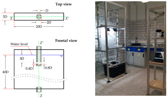
Figure 2.
Experimental rig used in this work. The dimensions of the scaled model are reported using the SEN bore diameter as normalization parameter.

Table 1.
Dimensions of the scaled model and operating conditions.
The experimental tests reported in Section 3 were recorded using a black and white 9501AZ High-Speed Camera from AZ-Instruments Corp (Taichung, Taiwan). In addition, the outlet jets of the SEN were illuminated using diverse configurations employing 2700-lumen LED floodlights. The images shown in Section 3.1 were taken with a Computar M6Z1212-3S lens, and due to its focal length, the distance between the central plane of the mold and the camera was 1.25 m. In contrast, the pictures shown in Section 3.2 were taken with a 6–60 mm, 720 p, F1.6, 1/3” CS lens. In this case, the distance between the outlet port of the SEN and the camera was 0.4 m.
A Chronos 1.4 color camera from Kron Technologies with a 6–60 mm, 720 p, F1.6, 1/3” CS lens was employed to record the experimental tests reported in Section 4. In addition, the mold was illuminated using diverse configurations employing 2700-lumen LED floodlights for the tests presented and analyzed in Section 4.1 and Section 4.3. On the other hand, a 500 mW, 450 nm laser module was employed to generate the 0.001 m thick lighting sheet for the PIV results presented in Section 4.2.
3. Analysis of the Outlet Jets
3.1. Frontal View
Figure 3 shows the nozzles employed to analyze the shape and characteristics of the SEN outlet jets from a frontal view. These nozzles are made from Plexiglass pipes. The bottom block of the SEN is a 3D-printed solid piece, whereas the flow divider is a rectangular cutout from a white-colored Plexiglass sheet. The pipe employed as the bore of the SEN has 0.025 m and 0.031 m of inner and outer radii, respectively. The outlet ports are pipes with 0.02 m and 0.026 m of inner and outer radii, respectively. Reducing the thickness of the SEN walls allows the observer to identify the hydrodynamic structures forming inside the SEN. In addition, this arrangement for the SEN makes it easy to directly compare the slopes of the outlet ports and the jets emerging from the SEN. Furthermore, the SEN exit-jet widening can be compared with the diameter of the outlet ports.

Figure 3.
Nozzles with reduced wall thickness employed for recording the SEN outlet jets’ shape from a frontal view. The FB, FBFD, WB, and WBFD-SEN with negatively tilted ports are shown in panels (a–d), whereas the WB-SEN with positively tilted ports is shown in panel (e).
Figure 3a–d show the FB, FBFD, WB, and WBFD nozzles with negatively tilted ports. Recall that the port slope is −15.0° in these nozzles. The structure of the SEN with positively tilted ports is illustrated through the WB-SEN shown in Figure 3e. The corresponding WBFD, FB, and FBFD nozzles are not shown to avoid redundancy. The port slope is +15.0° in these cases. The simplified nozzles shown in Figure 3 are conceived as a tool that improves the visualization of the SEN outlet jets’ features and the hydrodynamical structures forming inside it when the SEN discharges freely into the atmosphere. Therefore, it must be stressed that the authors do not propose using this simplified design as a final SEN for actual continuous-casting machines. The length of the outlet ports of the simplified design of the SEN is slightly longer than the thickness of the scaled SEN due to manufacturing restrictions.
The lighting conditions used to record each of the experimental tests reported in this subsection were as follows. First, the wide walls of the mold were illuminated using three LED floodlights. Two of them illuminated the frontal wall, and the other illuminated the rear wall. Next, an opaque but translucent plastic screen was placed between the mold rear wall and the LED floodlight to obtain a diffuse illumination behind the SEN.
The nozzle exit jets were recorded at 213 frames per second, with 1280 × 1024 image resolution. In addition, a set of 107 consecutive frames from each clip were employed to produce a combined picture by blending the images in the set using the “lighten” mode. This blending mode displays the entire path defined by all the jets in the set. Therefore, this procedure provides an image representing the SEN exit jets’ shape during 0.5 s. Finally, the combined images were edited to cut off the zones above and below the SEN exit jets.
The analysis of the exit jets for the nozzles with ports negatively tilted is presented in Figure 4, which is divided into four vertical panels. Each vertical panel shows the results of the corresponding nozzle operated under the five casting-speed values reported in Table 1. The images shown in Figure 4a–d belong to the FB, FBFD, WB, and WBFD-SEN.
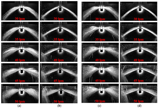
Figure 4.
Frontal view of the outlet jets of a nozzle with downwards-tilted ports as a function of the volumetric flow rate. (a) FB-SEN. (b) FBFD-SEN. (c) WB-SEN. (d) WBFD-SEN.
Figure 4 reveals several trends. Let us discuss the behavior unconnected with the casting speed increasing. First, the SEN exit-jet widening is broader for nozzles with a well bottom. Second, for the SEN with the flow divider, the exit jet on the left-hand side is almost perfectly symmetric with the jet on the other side. Third, the vertical widening of the outlet jets is narrower when the nozzles have the flow divider. In addition, due to its characteristic shape, the jets emerging from the nozzles with the flow divider strike directly on the narrow walls of the mold for all the casting speeds employed in these tests.
The nozzle exit-jet particularities listed previously agree with the analysis presented in Gonzalez et al. [18], where the hydrodynamics inside the SEN was studied, and the effect of adding the flow divider was also evaluated. Gonzalez et al. [18] showed that three different fluid flow patterns determine the hydrodynamics inside the SEN for the FB and the WB nozzles. One pattern is symmetric concerning a vertical plane aligned with the X–X’ symmetry axis of the SEN, shown in Figure 2. Concerning the same plane, the other two patterns are asymmetric, but they display reflective symmetry when comparing one with the other. The symmetric fluid flow pattern has two small counter-rotating vortices whose axes are parallel to the X–X’ symmetry axis. Vortices have almost the same size, and their height is located between the lower edge and the middle of the outlet ports. On the other hand, the asymmetric patterns have one huge vortex whose axis is far from the centerline of the SEN but parallel to the X–X’ symmetry axis.
Gonzalez et al. [18] also show that the nozzle exit jets are symmetric with minimum widening when only the symmetric fluid flow pattern is present. On the contrary, when the asymmetric pattern dominates the hydrodynamics inside the SEN, the nozzle exit jets are wide and asymmetric. Moreover, the jet wideness and asymmetry increase when the fluid flow inside the SEN alternates between the symmetric and the asymmetric patterns. Therefore, the flow divider generates narrow and symmetric nozzle exit jets by preventing the flow patterns from alternating.
Let us now discuss the behavior related to increasing casting speed. Figure 4 shows that regardless of the internal design of the SEN, the slopes of the upper and lower edges of the SEN exit jets change as the casting speed changes. However, the changes in the slope of the jet’s lower edge are minor for traditional nozzles, and no evident trend is observed. As a result, the slope of the lower edge of the SEN exit jet remains close to −35.0°. On the contrary, the slope of the lower edge decreases as the casting speed increases for nozzles with the flow divider. As a result, the slope of the lower edge decreases from −35° for the lowest casting speed to −24° for the highest casting speed.
The trend of the upper edge of the jet observed in Figure 4 is definite; its slope increases as the casting speed increases. However, notice that the change in the slope of the upper edge is less significant for nozzles with the flow divider. Therefore, the vertical widening of the outlet jets produced by the increase in the casting speed is narrower when the nozzles have the flow divider.
It was previously mentioned that for all the casting speeds reported in Figure 4, the jets emerging from the nozzles with the flow divider strike directly on the narrow walls of the mold. On the contrary, the jets emerging from the traditional nozzles mainly strike the wide walls of the mold and reach the narrow walls only at high casting speeds.
Figure 5 has four panels summarizing the results for the nozzles with ports positively tilted. This figure has the same organization as Figure 4; however, only the results for casting speeds of 0.8, 0.93, and 1.07 m/min are presented. The water drops generated by the splashing made the features of the nozzle exit-jets’ shapes indistinguishable for the other two casting speeds.
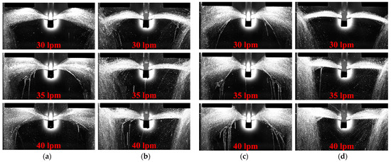
Figure 5.
Frontal view of the outlet jets of a nozzle with upwards-tilted ports as a function of the volumetric flow rate. (a) FB-SEN. (b) FBFD-SEN. (c) WB-SEN. (d) WBFD-SEN.
Figure 5 shows that regardless of the casting-speed value, the nozzles with positively and negatively tilted outlet ports share two particularities of their exit jets. First, the SEN exit-jet widening is broader for nozzles with well bottoms. Second, the vertical widening of the outlet jets is narrower when the nozzles have the flow divider. Figure 5 also shows that the exit jets become considerably wider regardless of the SEN inner geometry as the casting speed increases. Notice that the similarity between the outlet jets induced by the flow divider is lost for positively tilted outlet ports.
3.2. Top View
This subsection reports the analysis of the shape of the SEN outlet jets when increasing the casting speed from a top view. Several modifications to the experimental rig described in the previous subsection were made to record the experimental tests from the top view. Figure 6a shows the new camera location. The nozzles with reduced wall thickness employed in the previous subsection did not provide a helpful reference, so the nozzles employed in this subsection have squared external shapes. The inner characteristics of the WB, WBFD, FB, and FBFD-SEN with negatively tilted ports are shown in panels (b) to (e) of Figure 6. The external flat faces of the SEN accentuate the spatial location of the nozzle inside the mold cavity. Moreover, parallelism and perpendicularity between the external faces of the SEN and the wide walls of the mold become evident.

Figure 6.
Modification of the experimental rig for recording the SEN outlet jets’ shape from a top view. (a) New camera location. The inner characteristics of the WB, WBFD, FB, and FBFD-SEN with negatively tilted ports are shown in panels (b–e).
Regardless of the casting speed, it was observed that reflections and the jet splashing generated blurred images when recording the exit jets of nozzles with positively tilted ports. Consequently, the features of the outlet jets were indistinguishable in these images. Therefore, only nozzles with negatively tilted ports were studied.
The lighting conditions were also changed:
- Only one of the two wide walls of the mold was illuminated using a LED floodlight.
- Again, an opaque but translucent plastic screen was placed between the wide wall of the mold and the LED floodlight to obtain a diffuse illumination on one side of the SEN.
- Another opaque and entirely black plastic screen was now placed on the exterior face of the opposite wall to the illuminated one.
It was observed that the sharpness of the image decreased by locating the opaque plastic screen on the interior face of the wall opposite the illuminated one.
The nozzle exit jets were recorded at 213 frames per second, with 1280 × 1024 image resolution. In this case, blending a set of pictures, as used in the previous subsection, produces diffuse images due to the reflections on the wide walls of the mold. Thus, this approach was discarded. Instead, a characteristic image showing the main qualities of the jets was selected.
The analysis of the exit jets from a top view for the nozzles with ports negatively tilted is presented in Figure 7, which has the same organization as Figure 4 and Figure 5. This figure is divided into four vertical panels, and each vertical panel shows the results of the corresponding nozzle operated under the five casting-speed values reported in Table 1. The images shown in Figure 7a–d belong to the FB, FBFD, WB, and WBFD-SEN.
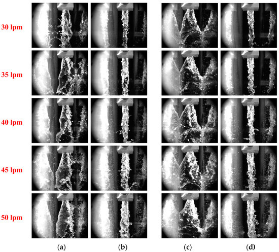
Figure 7.
Top view of the outlet jets as a function of the volumetric flow rate. (a) FB-SEN. (b) FBFD-SEN. (c) WB-SEN. (d) WBFD-SEN.
Figure 7 confirms several findings arising in the analysis from the frontal view and reveals that the shape of the nozzle exit jets displays several trends. Some of the trends disconnected from the casting speed are:
- The horizontal widening of the jets is broader for the WB-SEN than for the FB-SEN.
- The differences in the horizontal widening of the jets for the FBFD and WBFD-SEN are negligible at the same casting speed.
- The jets emerging from the nozzles with the flow divider are narrow and strike directly on the narrow walls of the mold.
- For the WB-SEN, the horizontal broadness of the jets is such that they simultaneously strike both wide faces of the mold.
Figure 7a shows that the horizontal broadness of the exit jets increases as the casting speed increases. Notice that at low casting speeds, the nozzle exit jet mainly strikes only one of two wide mold walls. Eventually, the jet inverts its horizontal tilt and strikes the opposite mold wall. When the casting speed is increased, the nozzle exit jet becomes broader enough that the exit jet simultaneously strikes both wide faces of the mold.
4. Hydrodynamic Behavior in the Mold Cavity
The fluid flow pattern in the mold cavity generated by each nozzle is studied in this section. The study is accomplished as follows:
- By analyzing the liquid-free surface shape and its stability.
- By reconstructing the fluid velocity field in the mold cavity through the PIV technique.
- By analyzing the distribution and the trajectories described by air bubbles emerging from the nozzle with the exit jets.
The experimental tests to analyze these three fundamental elements of the fluid flow pattern in the mold cavity were conducted using SENs with negatively tilted outlet ports. In addition, only one value for the casting speed was employed—1.07 m/s; that is, 40.0 L/min of volumetric flow.
Nozzles with squared external shapes were used for the experimental tests reported in this section to ensure parallelism between the external faces of the SEN and the wide walls of the mold. However, the present work does not propose using this SEN design in actual continuous-casting machines. It is clear that the external shape of the SEN influences the flow pattern inside the mold, especially near the SEN. However, this work focuses on the flow produced by the jets near the mold walls. Further work is necessary to evaluate the effects of the external geometry on the flow pattern around the SEN.
4.1. Liquid-Free Surface Analysis
The lighting conditions used to record the experimental tests reported in this subsection were as follows:
- A white opaque plastic screen was placed on the outer face of one of the wide walls of the mold.
- A LED floodlight illuminated the liquid in the mold cavity through the opposite wide wall.
- A translucent plastic screen was attached to the floodlight to obtain a direct but diffuse illumination of the liquid-free surface.
The shape of the liquid-free surfaces shown in Figure 8 confirms the roll structure or recirculation zone at the upper zone of the mold. This recirculation structure promotes the rising of the liquid-free surface height in the areas close to the nozzle and the narrow wall of the mold; consequently, a depression on the liquid-free surface shape arises. The valley location and the crest height of the resulting wave are closely related to the interaction of the ascending and descending flows involved. Furthermore, the stability of the wave is related to the crossflow, the stream flowing from one wide wall of the mold to the other.
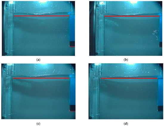
Figure 8.
Analysis of the liquid-free surface shape. (a) FB-SEN. (b) FBFD-SEN. (c) WB-SEN. (d) WBFD-SEN.
Comparing the shape of the waves for standard nozzles against nozzles with the flow divider, notice that the flow divider induces a reduction in the wave height. Additionally, notice that the flow divider displaces the wave valley to a new location close to the narrow wall of the mold. The combination of these two behaviors suggests that the zone at the liquid-free surface where the flow is ascending is narrower for nozzles with the flow divider. On the other hand, given that the flow divider reduces the wave fluctuations, it is reasonable to suppose that it also reduces the crossflow near the liquid-free surface.
In summary, the previous analysis of the liquid-free surface behavior suggests that the flow divider increases the fluid velocity in the mold cavity near the free surface, reducing the crossflow and the ascending and descending streams. However, this statement must be verified with liquid velocity measurements using intrusive and nonintrusive techniques.
4.2. Fluid Velocity Field in the Mold Cavity
Using the PIV technique, the fluid velocity field in the mold cavity was reconstructed onto two perpendicular planes. One plane is vertical, and its specifications are depicted in Figure 9. Notice that this plane is located in the middle of the mold and aligned with the symmetry axis X-X’, shown in Figure 2. The SEN submergence depth, Sd, was 0.075 m. The height, Hv, and the length, Lv, of the analyzed area or window are 0.12 m and 0.17 m, respectively. The analysis window does not include the liquid-free surface because reflections generated by the liquid-free surface make the particles in this zone indistinguishable. Therefore, the distance from the liquid-free surface to the upper window edge, Vg, is 0.03 m.

Figure 9.
Reconstruction of the fluid velocity field on a vertical plane inside the mold through the PIV technique.
The average liquid velocity field was reconstructed using 71 pairs of images with 800 × 600 resolution for each SEN. The elapsed time between the earliest images of two consecutive pairs is 50.0 milliseconds. Therefore, the set of images comprises a 3.5 s interval. In addition, the elapsed time between the images of each pair is 2.0 milliseconds. This time gap is small enough because the expected maximum liquid velocity is 0.5 m/s.
Figure 9 reports the average fluid velocity field for the FB, FBFD, WB, and WBFD-SEN. The roll at the upper zone of the mold is evident for the FB and WB nozzles. On the contrary, this roll is less evident for the nozzles with the flow divider. This behavior agrees with the findings reported in Gonzalez et al. [18]. The flow divider increases the velocity of the liquid near the bottom edge of the outlet jet. Despite this, the flow divider inside the SEN preserves the double-roll fluid flow pattern in the mold cavity. This assertion will become evident in the following subsection, in which air bubbles were used as tracers. The calculated liquid velocity fields also agree with the shapes of the liquid-free surface reported in Figure 8. The shapes of the liquid-free surfaces generated by the nozzles with the flow divider display low distortions. The liquid-free surface shape means that the flow divider reduces the turbulence near the liquid-free surface in the scaled model. Therefore, in an actual casting machine, it is reasonable to assume that the flow divider will help minimize the entrapment of the slag floating at the top of the liquid steel in the mold cavity.
The fluid velocity field was also reconstructed on the horizontal plane depicted in Figure 10. This study provides valuable information to complete the analysis presented previously. The plane is now perpendicular to the symmetry axis X–X’ and is located below the liquid-free surface. The height, Hh, and the length, Lh, of the analyzed area or window are 0.06 m and 0.17 m, respectively.
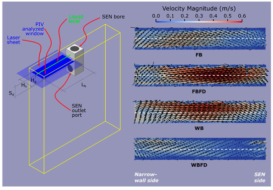
Figure 10.
Reconstruction of the fluid velocity field on a horizontal plane inside the mold through the PIV technique.
The SEN submergence depth, Sd, was 0.075 m, and the distance from the free surface to the upper window edge, Hg, was 0.045 m. Due to excessive reflections, considerable uncertainty in the velocity field reconstruction was observed for planes closer to the free surface. The average liquid velocity field was reconstructed using 71 pairs of images with 1280 × 720 resolution for each SEN. The elapsed time between the earliest images of two consecutive pairs is 50.0 milliseconds, and the elapsed time between the images of each pair is 2.0 milliseconds. Again, the expected maximum liquid velocity is close to 0.5 m/s.
Figure 10 shows that the flow divider promotes that most of the liquid mainly flows on a path parallel to the X–X’ symmetry axis. In addition, Figure 11 shows the liquid velocity magnitude along the white lines indicated in Figure 10, where the narrow wall of the mold is on the left-hand side, and the SEN is on the right-hand side. Notice that for the FBFD-SEN, the horizontal velocity magnitude is higher than for the FB-SEN. However, recall that the vertical velocity magnitude is considerably higher for the FB-SEN than the FBFD-SEN. Combining these behaviors explains why the turbulence near the free surface is low for the FBFD-SEN.
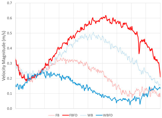
Figure 11.
Horizontal liquid velocity magnitude along the white lines indicated in Figure 10. The narrow wall of the mold is on the left-hand side and the SEN is on the right-hand side.
The apparent discrepancy between the magnitudes of velocity fields measured in two orthogonal planes observed in Figure 9 and Figure 10 is due to PIV measuring bias. The accuracy of the methods relies on the fact that most of the tracer particles stay enough time along the laser sheet. This is usually obtained by aligning the sheet with the main direction of the fluid flow. However, in nonhomogeneous flows strong perpendicular motions displace the tracers out of the plane and only a small fraction of tracers with plane-parallel motions will be registered. This is exactly the case for results presented in Figure 9 and Figure 10. In particular, the flow in FB SEN is dominated by ascending and descending motions, whereas FBFD has wide region with horizontal flow (Figure 9). A larger swirling motion for the FB model produces a larger XZ velocity magnitude than for FBFD. For this reason, when the measurement is made along the XY plane (Figure 10), the velocity field for FB SEN seems smaller.
4.3. Analysis of Air Bubbles Emerging from the SEN
The argon injection into the molten-steel stream entering the SEN is essential in actual slab continuous-casting machines because it helps to ensure the steel quality in several ways:
- By preventing the clogging of the SEN;
- By homogenizing the composition and temperature of the molten steel in the mold cavity; and
- By promoting the floating of nonmetallic inclusions.
The flow divider located in the SEN was designed as a device to impose symmetry inside the nozzle, delivering narrow and symmetric outlet jets, and therefore, producing a stable and symmetric flow pattern in the mold cavity. However, it was unknown how the flow divider would affect the stream of gas argon entering the SEN. This section analyzes the size distribution of air bubbles entering the mold cavity through the SEN outlet jets to answer this question. In addition, the trajectories described by the air bubbles indirectly reveal the fluid flow pattern in the mold cavity.
The air volumetric flow entering the SEN was 1.5 L/min. This value is consistent with the scaling of an actual slab continuous-casting machine. The lighting conditions used to record the air bubbles reported in this subsection are the same as that employed for recording the liquid-free surface in Section 4.1. The experimental tests were recorded at 2500 frames per second, with 800 × 600 image resolution. Then, 51 consecutive frames from each clip were employed to produce a combined picture by blending the images in the set using the “lighten” mode. This procedure renders a figure showing the path traveled by each bubble.
Figure 12 presents the trajectories described by the movement of the air bubbles in the mold cavity for the FB, FBFD, WB, and WBFD-SEN. Notice that the roll at the upper zone of the mold is visible for all the nozzles. In addition, notice that differences in the shapes of the roll and the nozzle outlet jet produced by the flow divider are evident. Furthermore, the fluid flow pattern depicted by the trajectories of the bubbles agrees with the analysis of the liquid-free surface and the velocity fields calculated with the PIV technique.
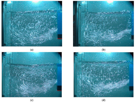
Figure 12.
Trajectories of the air bubbles entering the mold cavity. (a) FB-SEN. (b) FBFD-SEN. (c) WB-SEN. (d) WBFD-SEN.
It is well known that an inadequate bubble-size distribution will deteriorate the quality of the solidified steel [27,28,29,30,31]. Therefore, Figure 13 shows the “discretized” size of the air bubbles in the mold cavity when using FB, FBFD, WB, and WBFD-SEN. This figure reports the sizes of the bubbles on one image, randomly selected from the recorded clips. This figure reports a discretized size because the entire range of bubble areas was divided into seven intervals or bins. This information was employed to determine the size distribution of the air bubbles in the mold cavity when using FB, FBFD, WB, and WBFD-SEN, shown in Figure 14 as a histogram. Given that the amount of bubbles varies on each test, this figure reports the relative frequency. Notice that the flow divider changes the bubble-size distribution. Nevertheless, the differences between the distributions for the SEN with flow divider and its traditional counterpart are small enough. Therefore, it is reasonable to state that the flow divider neither increases the bubble breakage nor the coalescence between them.
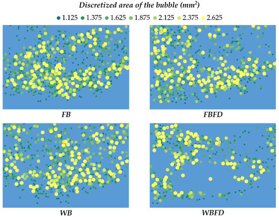
Figure 13.
Discretized size of the air bubbles in the mold cavity for each of the SEN designs.

Figure 14.
Histogram showing the size distribution of the air bubbles in the mold cavity for each of the SEN designs.
5. Concluding Remarks
The flow divider was envisioned as a static device that modifies the fluid flow pattern inside the SEN, and therefore, the shape and dynamics of the outlet jets. It was assumed that by producing symmetric, narrow, and stable jets emerging from the SEN, the hydrodynamic behavior of the liquid in the mold cavity would also be stable and characterized by a symmetric double-roll flow pattern. The experimental tests presented in this work show that the flow divider improves the performance of nozzles with negatively inclined outlet ports. It must be pointed out that all the experiments presented in Section 3 were recorded a little after the pump was turned on, ensuring previously that the features of the outlet jets were fully established. In addition, long-time observation of the experimental tests confirms that the pattern and dynamic behavior of the SEN outlet jets remain the same indefinitely. However, the difficulties presented in the experimental tests using nozzles with positively inclined outlets should be overcome in future works to establish the effect of the flow divider in these nozzles.
Several aspects must be analyzed to accurately establish the applicability in the industry of the flow divider. First, the stability of the liquid-free surface must be measured using intrusive and nonintrusive techniques in long-time experimental tests. In addition, the effect of the flow divider height and the presence of the tundish sliding gate must be evaluated.
Author Contributions
Conceptualization, J.G.-T., J.R.M.-T. and C.A.R.-R.; methodology, J.G.-T., C.A.R.-R., J.R.M.-T. and I.C.-M.; experimental tests, J.G.-T., J.R.M.-T. and F.C.-d.-l.-T.; PIV calculations, J.G.-T., F.C.-d.-l.-T. and R.G.; bubbles analysis, J.R.M.-T., J.G.-T. and F.S.-S.; writing—original draft preparation, J.G.-T., J.R.M.-T., R.G. and C.A.R.-R.; supervision, J.G.-T., F.C.-d.-l.-T. and R.G.; funding acquisition, C.A.R.-R., I.C.-M., F.S.-S. and J.R.M.-T. All authors have read and agreed to the published version of the manuscript.
Funding
This work was partially supported by Universidad Autonoma Metropolitana, grant number 22703022, PRODEP, grant number 22711777, and Instituto Politecnico Nacional, grant number SIP-20201315.
Institutional Review Board Statement
Not applicable.
Informed Consent Statement
Not applicable.
Data Availability Statement
Data are contained within the article.
Acknowledgments
The reconstruction of the fluid velocity field was carried out using the PIVlab software. The analysis of the bubbles was performed using the TrackMate software. The authors gratefully acknowledge anonymous referees for their comments and suggestions.
Conflicts of Interest
The authors declare no conflict of interest.
References
- Mills, N.T.; Barnhardt, L.F. Development of Submerged Entry Tundish Nozzles. JOM 1971, 23, 37–43. [Google Scholar] [CrossRef]
- Cai, C.; Shen, M.; Ji, K.; Zhang, Z.; Liu, Y. Research on the Influence of the Inner Wall Structure of the Continuous Casting Submerged Nozzle on the Stream of Molten Steel. Trans. Indian Inst. Met. 2022, 75, 613–624. [Google Scholar] [CrossRef]
- Szekely, J.; Yadoya, R.T. The Physical and Mathematical Modeling of the Flow Field in the Mold Region in Continuous Casting Systems: Part I. Model Studies with Aqueous Systems. Metall. Trans. 1972, 3, 2673–2680. [Google Scholar] [CrossRef]
- Yokoya, S.; Asako, Y.; Hara, S.; Szekely, J. Control of Immersion Nozzle Outlet Flow Pattern through the Use of Swirling Flow in Continuous Casting. ISIJ Int. 1994, 34, 883–888. [Google Scholar] [CrossRef]
- Odenthal, H.-J.; Pfeifer, H.; Lemanowicz, I.; Gorissen, R. Simulation of the Submerged Energy Nozzle-Mold Water Model System Using Laser-Optical and Computational Fluid Dynamics Methods. Metall. Mater. Trans. B 2002, 33, 163–172. [Google Scholar] [CrossRef]
- Cho, S.-M.; Thomas, B.G.; Lee, H.-J.; Kim, S.-H. Effect of Nozzle Port Angle on Mold Surface Flow in Steel Slab Casting; Association for Iron and Steel Technology; AISTECH: Barcelona, Spain, 2016; Volume 3, ISBN 9781935117551. [Google Scholar]
- Cho, S.-M.; Thomas, B.G.; Kim, S.-H. Effect of Nozzle Port Angle on Transient Flow and Surface Slag Behavior During Continuous Steel-Slab Casting. Metall. Mater. Trans. B 2019, 50, 52–76. [Google Scholar] [CrossRef]
- Sambasivam, R. Clogging Resistant Submerged Entry Nozzle Design through Mathematical Modelling. Ironmak. Steelmak. 2006, 33, 439–453. [Google Scholar] [CrossRef]
- Deng, X.; Ji, C.; Cui, Y.; Li, L.; Yin, X.; Yang, Y.; McLean, A. Flow Pattern Control in Continuous Slab Casting Moulds: Physical Modelling and Plant Trials. Ironmak. Steelmak. 2017, 44, 461–471. [Google Scholar] [CrossRef]
- Srinivas, P.S.; Mishra, D.K.; Kulkarni, A.B.; Gupta, R.; Korath, J.M.; Jana, A.K. Investigation of Vortex Flow Patterns at the Meniscus in a Water Caster Mould. Can. Metall. Q. 2020, 59, 211–232. [Google Scholar] [CrossRef]
- Gupta, D.; Lahiri, A.K. Water-Modeling Study of the Surface Disturbances in Continuous Slab Caster. Metall. Mater. Trans. B 1994, 25, 227–233. [Google Scholar] [CrossRef]
- Gupta, D.; Chakraborty, S.; Lahiri, A.K. Asymmetry and Oscillation of the Fluid Flow Pattern in a Continuous Casting Mould: A Water Model Study. ISIJ Int. 1997, 37, 654–658. [Google Scholar] [CrossRef]
- Gupta, D.; Lahiri, A.K. A Water Model Study of the Flow Asymmetry inside a Continuous Slab Casting Mold. Metall. Mater. Trans. B 1996, 27, 757–764. [Google Scholar] [CrossRef]
- Gupta, D.; Subramaniam, S.; Lahiri, A.K. Study of Fluid Flow and Residence-Time Distribution in a Continuous Slab Casting Mould. Steel Res. Int. 1991, 62, 496–500. [Google Scholar] [CrossRef]
- Gupta, D.; Lahiri, A.K. Water Modelling Study of the Jet Characteristics in a Continuous Casting Mould. Steel Res. Int. 1992, 63, 201–204. [Google Scholar] [CrossRef]
- Tsukaguchi, Y. Immersion Nozzle for Continuous Casting and Continuous Casting Method Using the Immersion Nozzle. U.S. Patent 10/586,346, 12 July 2007. [Google Scholar]
- Chaudhary, R.; Lee, G.-G.; Thomas, B.G.; Kim, S.-H. Transient Mold Fluid Flow with Well- and Mountain-Bottom Nozzles in Continuous Casting of Steel. Metall. Mater. Trans. B 2008, 39, 870–884. [Google Scholar] [CrossRef]
- Gonzalez-Trejo, J.; Gabbasov, R.; Miranda-Tello, J.R.; Carvajal-Mariscal, I.; Cervantes-de-la-Torre, F.; Sanchez-Silva, F.; Real-Ramirez, C.A. Analysis of a New SEN Design with an Inner Flow Divider. Metals 2021, 11, 1437. [Google Scholar] [CrossRef]
- Yuan, Q.; Vanka, S.P.; Thomas, B.G.; Sivaramakrishnan, S. Computational and Experimental Study of Turbulent Flow in a 0.4-Scale Water Model of a Continuous Steel Caster. Metall. Mater. Trans. B 2004, 35, 967–982. [Google Scholar] [CrossRef]
- Miranda, R.; Barron, M.A.; Barreto, J.; Hoyos, L.; Gonzalez, J. Experimental and Numerical Analysis of the Free Surface in a Water Model of a Slab Continuous Casting Mold. ISIJ Int. 2005, 45, 1626–1635. [Google Scholar] [CrossRef]
- Clyne, T.W.; Wolf, M.; Kurz, W. The Effect of Melt Composition on Solidification Cracking of Steel, with Particular Reference to Continuous Casting. Metall. Trans. B 1982, 13, 259–266. [Google Scholar] [CrossRef]
- Cheung, N.; Garcia, A. The Use of a Heuristic Search Technique for the Optimization of Quality of Steel Billets Produced by Continuous Casting. Eng. Appl. Artif. Intell. 2001, 14, 229–238. [Google Scholar] [CrossRef]
- Santos, C.A.; Spim, J.A.; Garcia, A. Mathematical Modeling and Optimization Strategies (Genetic Algorithm and Knowledge Base) Applied to the Continuous Casting of Steel. Eng. Appl. Artif. Intell. 2003, 16, 511–527. [Google Scholar] [CrossRef]
- Ramírez-López, A.; Muñoz-Negrón, D.; Palomar-Pardavé, M.; Romero-Romo, M.A.; Gonzalez-Trejo, J. Heat Removal Analysis on Steel Billets and Slabs Produced by Continuous Casting Using Numerical Simulation. Int. J. Adv. Manuf. Technol. 2017, 93, 1545–1565. [Google Scholar] [CrossRef]
- Real, C.; Miranda, R.; Vilchis, C.; Barron, M.; Hoyos, L.; Gonzalez, J. Transient Internal Flow Characterization of a Bifurcated Submerged Entry Nozzle. ISIJ Int. 2006, 46, 1183–1191. [Google Scholar] [CrossRef][Green Version]
- Real-Ramirez, C.A.; Carvajal-Mariscal, I.; Gonzalez-Trejo, J.; Miranda-Tello, R.; Gabbasov, R.; Sanchez-Silva, F.; Cervantes-de-la-Torre, F. Visualization and Measurement of Turbulent Flow inside a SEN and off the Ports. Rev. Mex. Fis. 2021, 67, 1–10. [Google Scholar] [CrossRef]
- Bessho, N.; Yoda, R.; Yamasaki, H.; Fujii, T.; Nozaki, T.; Takatori, S. Numerical Analysis of Fluid Flow in Continuous Casting Mold by Bubble Dispersion Model. ISIJ Int. 1991, 31, 40–45. [Google Scholar] [CrossRef][Green Version]
- Miki, Y.; Takeuchi, S. Internal Defects of Continuous Casting Slabs Caused by Asymmetric Unbalanced Steel Flow in Mold. ISIJ Int. 2003, 43, 1548–1555. [Google Scholar] [CrossRef]
- Kwon, Y.; Zhang, J.; Lee, H.-G. Water Model and CFD Studies of Bubble Dispersion and Inclusions Removal in Continuous Casting Mold of Steel. ISIJ Int. 2006, 46, 257–266. [Google Scholar] [CrossRef][Green Version]
- Liu, Z.; Li, B.; Jiang, M. Transient Asymmetric Flow and Bubble Transport Inside a Slab Continuous-Casting Mold. Metall. Mater. Trans. B 2014, 45, 675–697. [Google Scholar] [CrossRef]
- Wu, Y.; Liu, Z.; Wang, F.; Li, B.; Gan, Y. Experimental Investigation of Trajectories, Velocities and Size Distributions of Bubbles in a Continuous-Casting Mold. Powder Technol. 2021, 387, 325–335. [Google Scholar] [CrossRef]


Publisher’s Note: MDPI stays neutral with regard to jurisdictional claims in published maps and institutional affiliations. |
© 2022 by the authors. Licensee MDPI, Basel, Switzerland. This article is an open access article distributed under the terms and conditions of the Creative Commons Attribution (CC BY) license (https://creativecommons.org/licenses/by/4.0/).