Abstract
By means of comparing the VHCF response of heat-treated alloy steel, several factors governing the transition from surface (type I) to internal (type II) VHCF failure, and, in the case of internal inclusion and non-inclusion type II VHCF failure, are discussed: differences in strength, differences in grain size and strength gradients. Therefore, the steel grades (i) 50CrMo4 (0.5 wt%C–1.0 wt%Cr–0.2 wt%Mo) in two different tempering conditions (37HRC and 57HRC) but of the same prior austenite grain size, and (ii) 16MnCrV7 7 (0.16 wt%C–1.25 wt%Mn–1.7 wt%Cr) in the bainitic and martensitic thermomechanical treatment state, were studied. It is concluded that steels of moderate strength (37HRC) exhibit a real endurance limit (109 cycles), while the fatigue strength of high strength (43–57HRC) or coarse-grained steels (37HRC) decreases with increasing number of load cycles.
1. Introduction
Heat-treated alloy steels, i.e., tempered martensitic or bainitic steels are used in virtually all kinds of engineering applications that involve cyclic deformation under high or very high cycle fatigue conditions (HCF, VHCF), e.g., power trains in transportation, and gearboxes or crankshafts in power generation. In most cases, the VHCF life of heat-treated alloy steels is limited by internal crack initiation manifesting as a characteristic fisheye-like fracture surface. As a typical feature, the crack initiation site is surrounded by a fine-granular area (FGA), also known as an optically dark area (ODA) [1,2,3], from which the fatigue crack propagates within the fisheye until the residual cross-section fails by final fracture. This is called type II VHCF behavior [4]. Contrary to this, LCF, HCF, and sometimes VHCF conditions lead to surface crack initiation, which can be attributed to (i) plane stress, and (ii) environmentally-induced slip irreversibility, both promoting pronounced stress concentration (type I VHCF behavior [4]). At the very low stress amplitudes in the macroscopically elastic regime prevailing during VHCF, any dislocation plasticity at the surface vanishes due to work hardening (shakedown). In this case, the material may exhibit a real infinite life since any initial fatigue damage is permanently stopped. In the case of internal microstructure inhomogeneities, such as non-metallic inclusions, selected grain-boundary triple points, or favorably oriented slip planes [5,6], strong stress concentrations in the bulk become dominant. Under plane-strain conditions, these high stress levels initiate local plastic slip, which accumulates during millions of cycles, eventually leading to fracture at the inhomogeneity, appearing as a so-called “fisheye”, where the fatigue crack propagates within a circular shape around the crack initiation site until rupture of the residual cross-section. Since the local stress concentration is associated with the size of the microstructure inhomogeneity, i.e., expressed by the projected area of a non-metallic inclusion normal to the applied load direction, and the strength of the material (that is expressed by means of the Vickers hardness HV), Murakami [7] suggested a simple, but widely-applied equation to estimate the fatigue limit σFL:
with R referring to the stress ratio, and α and C being material constants. When having a closer look at the crack initiation site, it has been found many times that the origin is surrounded by an FGA/ODA. Its granular appearance has been attributed to a cyclic rearrangement of dislocations, polygonization, and, eventually, the formation of nano-sized grains [8,9,10]. VHCF crack propagation at a stress intensity range ∆K lower than the threshold ∆Kth may be attributed (i) to the particularly low resistance of the nano-grained FGA structure to fatigue cracking, (ii) accumulation of hydrogen [1,11], or (iii) to the repeated pressing of the crack faces on top of each other leading to crack closure within the FGA [12,13]. Only if the stress intensity range exceeds the threshold value ∆Kth for long fatigue cracks, does the FGA turn into a conventional fatigue fracture pattern [9,14], showing, e.g., striations, being characteristic of long fatigue cracks [15].
To date, the correlation of the material microstructure with the VHCF strength remains challenging and often impossible. Data from different research institutes show a pronounced scatter of service life data often in the range of three orders of magnitude. This can be attributed to two major aspects:
- The significance of microstructure inhomogeneity becomes prevailing in VHCF, since the lower the applied stress amplitude, the smaller the number of stress concentration sites that lead to accumulated cyclic plasticity.
- The frequency effect: testing at higher frequencies often leads to an apparent increase in the VHCF strength.
According to Jeddi and Palin-Luc [16], one can distinguish between (i) intrinsic effects, such as strain rate sensitivity of dislocation plasticity, adiabatic local heating and recrystallization, or dynamic strain ageing; and (ii) extrinsic effects, such as oxide-induced crack closure or atmospheric slip irreversibility. In addition, sample size effects have to be considered, i.e., the larger the stressed volume, the lower the fatigue strength. As an example, Figure 1 shows the pronounced frequency effect of plain 0.15% carbon steel [17].
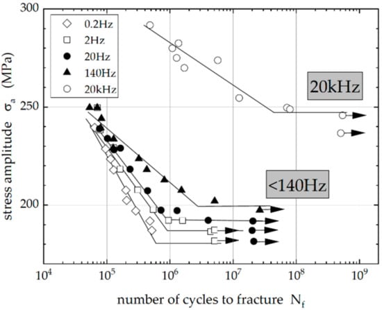
Figure 1.
Wöhler S-N Diagram showing the fatigue life for C15 (0.15% carbon) steel at various testing frequencies [17].
In addition, Geilen et al. [18] suggested an influence of the control mode. Although resonance and servohydraulic HCF/VHCF testing is usually stress-controlled, ultrasonic testing is displacement-controlled, i.e., the displacement is adjusted according to linear elastic behavior. However, when cyclic plasticity needs to be taken into account, the adjusted displacement is below the actual value, hence leading to longer fatigue lives and apparently higher VHCF strength values, which can be interpreted as a frequency effect. However, in the case of the steel grades and strength values that are the subject of the present study, the macroscopic stress level should be completely within the elastic regime.
The present paper highlights microstructure effects on the existence or non-existence of a fatigue limit and the occurrence or non-occurrence of an FGA. The frequency effect is attributed to the strain rate dependency of dislocation plasticity that varies with the tempering state and the respective strength of the steel.
2. Materials Processing and VHCF Testing Approach
Two different grades of low-alloy steels 50CrMo4 (1.7228, German designation) and 16MnCrV7 7 (1.8195, German designation), respectively, were used for this study. The chemical composition of the alloys is given in Table 1.

Table 1.
Chemical composition of the two steels A and B used in this study (in wt%).
A martensitic microstructure was adjusted for 50CrMo4. For this purpose, round bar sections of 50CrMo4 were austenitized at a temperature of 860 °C and then quenched in oil. By suitably modifying the tempering temperature, two hardness conditions of 37HRC at a tempering temperature of 550 °C and 57HRC at 200 °C were achieved. The tempering duration did not alter the prior austenite grain size of 12 µm and was kept for 90 min each. Figure 2 shows the microstructures of the two 50CrMo4 tempering conditions, 37HRC and 57HRC, respectively.
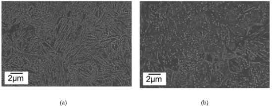
Figure 2.
SEM micrographs of the tempered microstructure of 50CrMo4 austenitized at 860 °C, quenched in oil, and tempered at (a) 200 °C leading to 57HRC, and (b) 550 °C leading to 37HRC.
In the case of 16MnCrV7 7, cylindrical samples were forward hot-extruded at 1250 °C and 950 °C, respectively, within a 1000 kN screw press (Weingarten) and subsequently quenched according to defined conditions: (i) pressurized-air quenching to 260 °C followed by slow cooling within the furnace throughout the lower-bainite transformation regime (dashed line in the TTT diagram, Figure 3), and (ii) water-quenching below martensite start (Ms) followed by ambient air cooling (self-tempered martensite, dotted line in the TTT diagram, Figure 3). Due to the different forging temperatures, the prior austenite grain size and the non-equilibrium ferrite lath size are larger in the lower bainite structure as compared to the self-tempered martensite structure, as shown in the EBSD inserts in Figure 3.
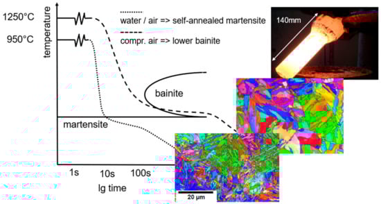
Figure 3.
Thermomechanical processing by means of two different cooling routes in a schematic TTT diagram for the steel 16MnCrV7 7 applied to forward hot-extruded cylindrical bars (diameter 50 mm).
The thermomechanical heat treatment outlined above led to a lath-type microstructure with cementite platelets of about 200 nm length, tilted by 60° towards the laths axes in the case of the lower bainitic structure (prior austenite grain size 53 µm, cf. Figure 4a), and with nano-sized cementite precipitates of about 50–100 nm size in the case of the self-tempered martensite (prior austenite grain size 8 µm, cf. Figure 4b). It is worth mentioning that the self-tempered martensite shows not only high static stress values but also a surprisingly high toughness of Av = 104 J at room temperature (Charpy test data, Table 2).
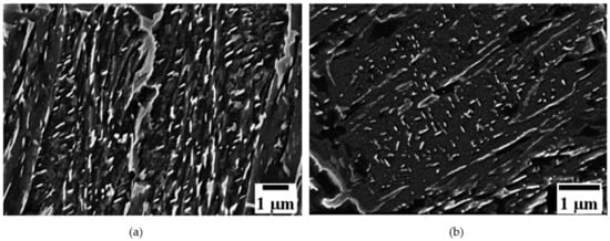
Figure 4.
SEM micrographs of thermomechanically-processed steel 16 CrMnV7 7: (a) lower bainite with cementite platelets, and (b) self-tempered martensitic microstructure with homogeneously distributed small cementite precipitates.
Table 2.
Mechanical properties of the steel grades used in the present study.
Fatigue specimens were machined from the heat-treated sections according to the geometries provided in Figure 5. The gauge lengths of the specimens were electrolytically polished for 3 min using Struers A2 electrolyte at a voltage of 23 V and a temperature of −15 °C. For in situ damage monitoring by light optical microscopy (Hirox long-distance digital microscope, Limonest, France, Figure 5a), high-resolution thermography, and SEM, the specimens were given a shallow notch with a notch factor of 1.1 (details and results are reported in [18,19]). The shallow notch allows the restriction of surface fatigue damage to a limited area without changing the microstructure-related crack initiation process. Fatigue testing was carried out in a resonance testing machine (Rumul Testronic, Neuhausen, Switzerland, 95 Hz, Figure 5a) and an ultrasonic fatigue testing system (Boku Vienna, 20 kHz, Figure 5b) at fully reversed loading conditions (R = −1). The temperature increase in the specimens during high-frequency testing was limited to 40 °C by pressurized air-cooling and applying the pulse–pause operation mode of the ultrasonic fatigue testing system, i.e., 50 ms pulse and 950 ms pause in the moderate strength conditions (37HRC) and 200 ms pulse and 800 ms pause in the higher strength conditions (43HRC–57HRC).
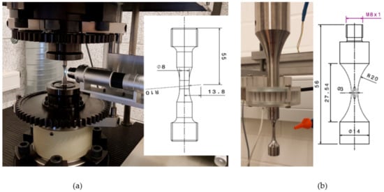
Figure 5.
Specimen geometries (all dimensions in millimeters) for (a) the resonance fatigue testing system RUMUL Testronic (95 Hz), and (b) the ultrasonic fatigue testing equipment of the type BOKU Vienna (20 kHz).
In addition to the quasi-static tensile tests, high strain rate tests were carried out using a 15 kN RoellAmsler servohydraulic high-rate testing system with a specimen geometry, as shown in Figure 6.
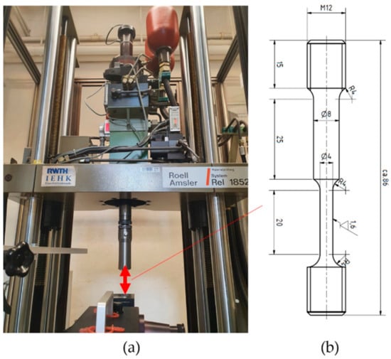
Figure 6.
(a) Servohydraulic high-speed testing system (15 m/s) and (b) respective sample geometry (all dimensions in millimeters). The larger diameter is used for optoelectronic strain measurement type Zimmer 200XH.
3. Results
The different microstructure states and strength levels of the steels resulted in a variety of different damage mechanisms, which are briefly introduced in the following. The 50CrMo4 steel in the moderate strength condition (50CrMo4—37HRC) shows type I fatigue behavior, i.e., during cycling, persistent slip markings (PSM) are formed at the surface within Cr-depleted segregation bands, leading to crack initiation. Crack propagation was found only at stress amplitudes higher than 680 MPa. In these cases, failure occurred generally in the HCF regime (Nf < 107 cycles). At lower stress amplitudes, PSMs and cracks were identified (Figure 7), but the propagation of these was eventually blocked by microstructural barriers, i.e., martensite packet boundaries and prior austenite grain boundaries, respectively. Therefore, it was concluded that in a moderate strength condition, tempered martensitic steels may exhibit a true fatigue limit.
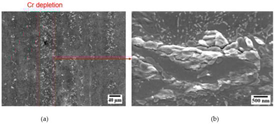
Figure 7.
(a) Localized fatigue damage in Cr depleted zones, (b) persistent slip markings (PSM) at the surface of the 50CrMo4—37HRC steel, tested at 95 Hz, σa = 480 MPa.
In the high-strength condition steel, 50CrMo4—57HRC, the fatigue damage behavior is completely different. Internal VHCF crack initiation at 10–20 µm-sized nonmetallic Al2O3∙CaO-type inclusions forming the center of the fisheye (red circle) prevails (Figure 8a). As outlined in the introduction, the crack initiation site is surrounded by a fine granular area (FGA), as shown in Figure 8b.
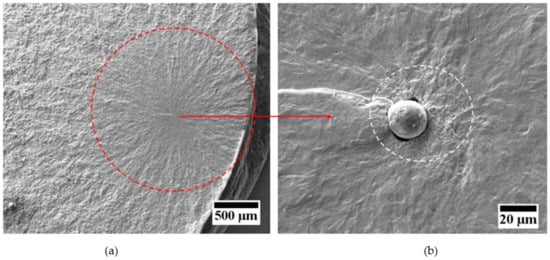
Figure 8.
Fracture surface of the 50CrMo4—57HRC steel with a fisheye ((a), red circle) and crack initiation at a non-metallic inclusion (type Al2O3-CaO) surrounded by FGA ((b), white circle), tested at 95 Hz, σa = 480 MPa.
The Wöhler S/N data were determined using both 95 Hz and 20 kHz fatigue testing at R = −1 for the four different steel grades, as shown in Figure 9 and Figure 10. Two major observations should be highlighted:
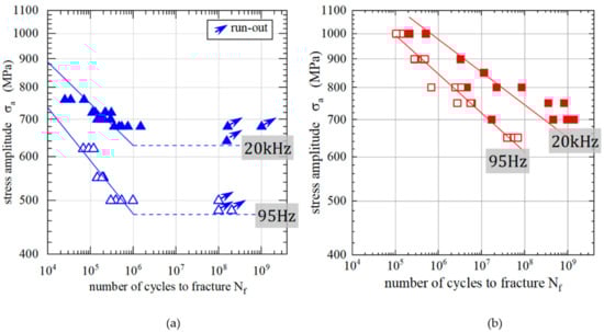
Figure 9.
Wöhler S-N Diagram showing the fatigue life for the steel 50CrMo4 at two testing frequencies of f = 95 Hz and f = 20 kHz for (a) the 37HRC hardness condition, and (b) the 57HRC hardness condition.
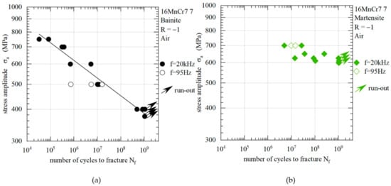
Figure 10.
Wöhler S-N Diagram showing the fatigue life for the 16 MnCrV7 7 steel at two testing frequencies of f = 95 Hz and f = 20 kHz for (a) the bainitic, and (b) the self-tempered martensitic condition.
The moderate-strength 50CrMo4—37HRC grade seems to reveal a true fatigue limit. No fractures were observed beyond 107 cycles. SEM studies supported by FIB (focused ion beam sections) through PSMs at the surface proved the occurrence of fatigue cracks (cf. Figure 7b and [20]) as a result of the classical extrusion–intrusion scheme (cf. [15,21]). In the case of the high-strength 50CrMo4—57HRC grade, a continuous decrease in the fatigue strength with increasing numbers of cycles to fracture was observed. Fracture was found even at 109 cycles, and in all cases, the fatigue damage mechanism was internal crack initiation along with FGA formation. The size of the FGA was found to increase with decreasing stress amplitude, supporting the hypothesis of a crack propagation mechanism that is driven by accumulated dislocation plasticity and nanograin formation at stress intensity ranges lower than the threshold value ∆Kth from linear elastic fracture mechanics (LEFM).
As a second observation, a pronounced frequency shift of the fatigue stress data only in the case of the moderate-strength 50CrMo4—37HRC grade was observed. The high strength 50CrMo4—57HRC grade reveals only slightly higher fatigue strength values for 20 kHz testing as compared with the 95 Hz testing. Although the strong effect is attributed to a strain rate dependency of dislocation plasticity (see discussion), the smaller effect is probably due to a size effect, since the stressed volume of the specimens tested at 20 kHz (V20kHz = 125 mm3,) is substantially smaller than the ones for the 95 Hz resonance testing (V95Hz = 402 mm3).
The fatigue strength data for the thermomechanically-processed 16MnCrV7 7 specimens are shown in Figure 10. Analogous to the tensile test data, the fatigue strength of the tempered martensite processing state is higher than that of the lower bainite processing state. It is worth mentioning that the self-tempered martensite outperforms the lower bainite. The fatigue limit is estimated as σFL = 600 MPa, which is surprisingly high and corresponds to 44% of the quasi-static UTS.
In the lower bainite state, a continuous decrease in the fatigue strength was observed with fractures occurring even at 109 cycles at the rather low stress amplitude of σa = 400 MPa (34% UTS). A pronounced frequency effect was not observed, but the amount of 95 Hz data is not sufficient to draw a sound conclusion on that aspect. In thermomechanically-processed 16MnCrV7 7 samples, VHCF crack initiation was found to occur exclusively internally at Nf > 107 (Figure 11). Although in the self-tempered martensite microstructure 10–20 µm-sized non-metallic inclusions act as relevant stress concentrators (Figure 11a), internal crack initiation in the lower bainite microstructure does not come with any inclusions (Figure 11b). This was attributed to the rather large prior austenite grain size of 53 µm, which may cause high stress concentrations at grain boundary triple points, being higher than those at the non-metallic inclusions, which should, instead, be identical to the tempered martensite condition.
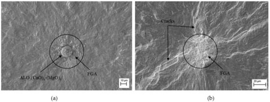
Figure 11.
Fatigue crack initiation sites in 16MnCrV7 7: (a) internal crack initiation at non-metallic inclusion (tempered martensite, 43HRC, σa = 625 MPa, N = 0.9 × 10⁸), and (b) internal crack initiation at a grain boundary triple point (presumed) (37HRC, σa = 400 MPa, N = 8.7 × 10⁸).
4. Discussion
The two steel grades 50CrMo4 and 16MnCrV7 7 in two different heat treatment conditions each showed a strong relationship between the microstructure, static strength and the VHCF behavior. The moderate strength condition of 50CrMo4—37HRC revealed only surface fatigue damage manifesting itself in persistent slip markings—typically parallel to the martensite block boundaries. Generally, crack initiation was identified at those slip markings, but at sufficiently low stress amplitudes (see Figure 12) these cracks were considered as non-propagating., i.e., the conditions of a true fatigue limit seemed to be fulfilled.
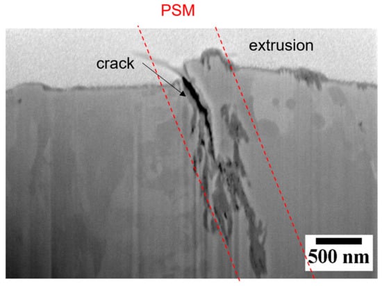
Figure 12.
FIB section through a persistent slip marking (PSM) at the surface of the 50CrMo4—37HRC steel, tested at 95 Hz, σa = 480 MPa, run out after 2 × 10⁸ cycles, showing crack initiation and void formation.
In the case of the high-strength 50CrMo4—57HRC grade and the two 16MnCrV7 7 microstructure variants, internal crack initiation at inhomogeneities was observed. In many cases, initiation was attributed to Al2O3-CaO-type non-metallic inclusions of a size of approximately 10–20 µm that cause stress concentrations due to elastic mismatch. The inclusions themselves were found to be surrounded by fine granular areas (FGA). The size of the FGA (measured as the projected area normal to the loading axis) was observed to increase with decreasing applied stress amplitude.
Evaluating the different sizes of the FGAs of many VHCF samples revealed that the stress intensity range associated with the FGA ∆KFGA, as calculated according to Murakami (internal circular crack):
is of a constant value, i.e., ∆KFGA ≈ 8.5 MPa m0.5 which is close to the value measured by a fracture mechanics threshold analysis, where a threshold stress intensity of ∆Kth = 9.5 MPa m0.5 was obtained (cf. [19,20]). Accordingly, it was concluded that the stress intensity calculated for the inclusion is too small for technical crack initiation, ∆Kincl. < ∆Kth. Due to accumulated microplasticity, dislocation patterning and polygonization, a nanograin structure is formed around the inclusion. As the stress intensity threshold for fine-grained microstructures is smaller than for coarse-grained microstructures, a fatigue crack is initiated at the inclusion, since now ∆Kincl. > ∆Kth,nanograin. This kind of crack propagation within the nanograin microstructure forms the FGA and prevails until, at the crack tip, ∆K = ∆KFGA > ∆Kth is valid. Then, the crack propagation mechanism changes towards the long fatigue crack regime within the fish-eye until at KIc the transition to unstable crack propagation (final rupture) is reached.
Figure 13 shows FIB sections through FGAs emanating from an inclusion and a microstructure inhomogeneity (probably a grain-boundary triple point). In particular, Figure 13a shows the rim of nanograins that form the FGA at an Al2O3-type inclusion.
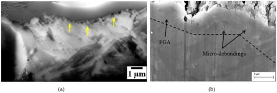
Figure 13.
FIB sections through the internal crack initiation sites in (a) 50CrMo4—57HRC: nanograins within the FGA (yellow arrows) at an Al2O3-type inclusion (57HRC, σa = 750MPa, N = 3.5 × 10⁸), and (b) 16MnCrV7 7 lower bainite: an FGA without any non-metallic inclusion (σa = 400 MPa, N = 8.7 × 10⁸).
The results revealed that VHCF strength data are not independent of the testing frequency, which has been observed by others (cf. [22,23]). Although it is well-known that effects of the environment, e.g., corrosion fatigue or oxide-induced crack closure, lead to a time-dependent fatigue behavior [24], the use of ultrasonic testing frequency implies substantially high strain rates:
This, in turn, is necessary to determine the VHCF material properties in a reasonable time. Accordingly, at 20 kHz, a maximum strain rate of = 500 s−1, and at 95 Hz, a maximum strain rate of = 2 s−1 is reached. For bcc materials such as carbon steel, a temperature/strain rate dependence of dislocation plasticity is known. According to Seeger [25], the critical shear stress of a bcc material can be subdivided into an athermal contribution τ0 (dislocation shearing/passing) and a thermally-activated contribution τ* (Peierls stress):
Figure 14a,b shows the two contributions. In the case of moderate strength (Figure 14a), τ0 is rather low and at high strain rates, the increase in τ* leads to an apparent increase in the yield stress. In the high-strength condition (Figure 14b), the high-strain rate effect vanishes due to the high τ0 contribution. This hypothesis (cf. [26]) is supported by dynamic tensile testing at strain rates between = 1 s−1 and = 500 s−1. The results (Figure 14c) show for the 50CrMo4—57HRC high-strength condition a negligible strain rate dependence, while for the 50CrMo4—37HRC moderate-strength condition, the strain rate dependence leads to an approximately 30% increase in yield stress.
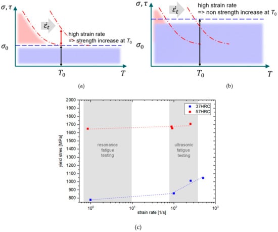
Figure 14.
Schematic sketch of the temperature dependence of the critical shear/yield stress: red lines: the thermally-activated contribution (increases with increasing strain rate), blue lines: the athermal contribution in (a) moderate-strength alloys, and (b) high-strength alloys; and (c) yield stress vs. strain rate for the two 50CrMo4 steel grades.
The given fatigue life data and high-strain static stress values show a positive correlation between fatigue test frequency and static strain rate and provide evidence that the slip behavior of the dislocations is generally influenced. The reason for this is assumed to be a restriction of movement of the dislocations. Due to the lattice structure, bcc materials have a very high Peierls potential. This results in a significant expenditure of energy to overcome a maximum of the Peierls potential in order to slide into the next minimum. This leads to an essential property at low temperatures or high strain rates: the mobility of edge dislocations is much higher than the mobility of screw dislocations. Because of this restriction of motion, only segments of long screw dislocations are usually found under high-strain cyclic plastic deformation and no cell or ladder structures, as is otherwise common under fatigue loading [27,28,29]. A key aspect in identifying the influence of the test frequency is the consideration of the material condition, e.g., heat treatment. A higher dislocation density leads to an increase in τ0 according to Figure 14b. However, this also includes a consideration of the distribution of the alloying elements, e.g., carbon, which, in turn, has a significant influence on the strain rate effect itself [30]. Therefore, it becomes clear that knowledge about the relationship between the material structure and the movement of dislocations is essential for a clear explanation of the phenomenon of the frequency influence.
5. Conclusions
The VHCF damage of tempered martensitic and bainitic steels depends strongly on the microstructure and the strength level that are adjusted by heat treatment:
- At moderate strength level (martensitic 50CrMo4, 37HRC), irreversible surface plasticity prevails and leads to the formation of persistent slip markings (PSM). Depending on the local combination of stress concentration and microstructural barrier strength, the steel may exhibit a true fatigue limit, below which the fatigue life can be considered as infinite.
- At high strength levels (martensitic 50CrMo4, 57HRC, martensitic 16MnCrV 7 7), the stress concentration at internal non-metallic inclusions leads to an accumulation of dislocation plasticity, patterning, grain refinement, and crack initiation in combination with the formation of a fine granular area (FGA). The lower the remote stress amplitude, the larger the FGA, the size of which correlates with the stress intensity threshold ∆Kth for long fatigue cracks.
- In the case of large inhomogeneities, such as the coarse prior austenite grains in the bainitic 16MnCrV 7 7, pronounced stress concentrations at triple points lead to internal crack initiation, even at lower strength levels. Here, FGAs without non-metallic inclusion were observed.
When applying ultrasonic frequencies for VHCF testing, strain rate effects need to be taken into consideration, which can be evaluated by dynamic tensile testing. In the case of low- and moderate-strength steels, high strain rates ( = 500 s−1 in ultrasonic testing) cause an apparently higher VHCF strength (∆σ = 50–200MPa) as compared to low strain rates ( < 5 s−1 in resonance/servohydraulic testing).
Author Contributions
Conceptualization, U.K. and A.G.; methodology, U.K. and A.G.; software, A.G.; validation, U.K. and A.G.; formal analysis, A.G.; investigation, A.G.; resources, U.K.; data curation, A.G.; writing—original draft preparation, U.K.; writing—review and editing, U.K. and A.G.; visualization, U.K. and A.G.; supervision, U.K.; project administration, U.K.; funding acquisition, U.K. All authors have read and agreed to the published version of the manuscript.
Funding
This research was funded by the Volkswagen foundation in the framework of the research priority program OPTIHEAT grant number VWZN2841 and the German Ministry of Education and Research (BMBF) grant number 03FH011IX4.
Data Availability Statement
The study did not report any data.
Acknowledgments
The German Ministry of Education and Research (BMBF), and the supply of steel specimen material by Georgsmarienhütte Steel and Bosch GmbH are gratefully acknowledged.
Conflicts of Interest
The authors declare no conflict of interest.
References
- Murakami, Y.; Nomoto, T.; Ueda, T. On the mechanism of fatigue failure in the superlong life regime (N > 107 cycles). Part 1: Influence of hydrogen trapped by inclusions. Fatigue Fract. Eng. Mater. Struct. 2000, 23, 893–902. [Google Scholar] [CrossRef]
- Murakami, Y.; Nomoto, T.; Ueda, T. On the mechanism of fatigue failure in the superlong life regime (N > 107 cycles). Part II: Influence of hydrogen trapped by inclusions. Fatigue Fract. Eng. Mater. Struct. 2000, 23, 903–910. [Google Scholar] [CrossRef]
- Murakami, Y.; Yokoyama, N.N.; Nagata, J. Mechanism of fatigue failure in ultralong life regime. Fatigue Fract. Eng. Mater. Struct. 2002, 25, 735–746. [Google Scholar] [CrossRef]
- Mughrabi, H. Specific Features and Mechanisms of Fatigue in the Ultrahigh-Cycle Regime. Int. J. Fatigue 2006, 28, 1501. [Google Scholar] [CrossRef]
- Chai, G.C. The formation of subsurface non-defect fatigue crack origins. Int. J. Fatigue 2006, 28, 1533–1539. [Google Scholar] [CrossRef]
- Chai, G.C. On Fatigue Crack Initiation in the Matrix in Very High Cycle Fatigue Regime. Mater. Sci. Forum 2014, 783–786, 2266–2271. [Google Scholar] [CrossRef]
- Murakami, Y.; Endo, M. Effects of defects, inclusions and inhomogeneities on fatigue strength. Int. J. Fatigue 1994, 16, 163–182. [Google Scholar] [CrossRef]
- Sakai, T. Review and prospects for current studies on very high cycle fatigue of metallic materials for machine structural use. JMMP 2009, 3, 425–439. [Google Scholar] [CrossRef]
- Grad, P.; Reuscher, B.; Brodyanski, A.; Kopnarski, M.; Kerscher, E. Mechanism of fatigue crack initiation and propagation in the very high cycle fatigue regime of high-strength steels. Scr Mater. 2012, 67, 838–841. [Google Scholar] [CrossRef]
- Grabulov, A.; Ziese, U.; Zandbergen, H.W. TEM/SEM investigation of microstructural changes within the white etching area under rolling contact fatigue and 3-D crack reconstruction by focused ion beam. Scr Mater. 2007, 57, 635–638. [Google Scholar] [CrossRef]
- Murakami, Y.; Kanezaki, T.; Sofronis, P. Hydrogen embrittlement of high strength steels: Determination of the threshold stress intensity for small cracks nucleating at nonmetallic inclusions. Eng. Fract. Mech. 2013, 97, 227–243. [Google Scholar] [CrossRef]
- Hong, Y.; Sun, C. The Nature and the Mechanism of Crack Initiation and Early Growth for Very High Cycle Fatigue of Metallic Materials—An Overview. Theor. Appl. Fract. Mech. 2017, 92, 331. [Google Scholar] [CrossRef]
- Hong, Y.; Lei, Z.; Sun, C.; Zhao, A. Propensities of crack interior initiation and early growth for very- high-cycle fatigue of high strength steels. Int. J. Fatigue 2014, 58, 144–151. [Google Scholar] [CrossRef]
- Krupp, U.; Giertler, A.; Koschella, K. Microscopic damage evolution during very-high-cycle fatigue (VHCF) of tempered martensitic steel. Fatigue Fract. Eng. Mater. Struct. 2017, 40, 1731. [Google Scholar] [CrossRef]
- Suresh, S. Fatigue of Materials; Cambridge University Press: Cambridge, MA, USA, 1998. [Google Scholar]
- Dalenda, J.; Thierry, P.-L. A review about the effects of structural and operational factors on the gigacycle fatigue of steels. Fatigue Fract. Eng. Mater. Struct. 2018, 41, 969–990. [Google Scholar]
- Guennec, B.; Ueno, A.; Sakai, T.; Takanashi, M.; Itabashi, Y. Effect of the loading frequency on fatigue properties of JIS S15C low carbon steel and some discussions based on micro-plasticity behavior. Int. J. Fatigue 2014, 66, 29–38. [Google Scholar] [CrossRef]
- Geilen, M.B.; Schönherr, J.A.; Klein, M.; Leininger, D.S.; Giertler, A.; Krupp, U.; Oechsner, M. On the Influence of Control Type and Strain Rate on the Lifetime of 50CrMo4. Metals 2020, 10, 1458. [Google Scholar] [CrossRef]
- Giertler, A. Mechanismen der Rissentstehung und -ausbreitung im Vergütungsstahl 50CrMo4 bei sehr hohen Lastspielzahlen. Ph.D. Thesis, RWTH Aachen University, Aachen, Germany, 2020. [Google Scholar]
- Giertler, A.; Krupp, U. Investigation of Fatigue Damage of Tempered Martensitic Steel during High Cycle Fatigue and Very High Cycle Fatigue Loading Using In Situ Monitoring by Scanning Electron Microscope and High-Resolution Thermography. Steel Res. Int. 2021, 92. [Google Scholar] [CrossRef]
- Man, J.; Petrenec, M.; Obrtlík, K.; Polák, J. AFM and TEM study of cyclic slip localization in fatigued ferritic X10CrAl24 stainless steel. Acta Mater. 2004, 52, 5551–5561. [Google Scholar] [CrossRef]
- Kikukawa, M.; Ohji, K.; Ogura, K. Push-Pull Fatigue Strength of Mild Steel at Very High Frequencies of Stress Up to 100 kc/s. J. Basic Eng. 1965, 87, 857–864. [Google Scholar] [CrossRef]
- Torabian, N.; Favier, V.; Dirrenberger, J.; Adamski, F.; Ziaei-Rad, S.; Ranc, N. Correlation of the high and very high cycle fatigue response of ferrite based steels with strain rate-temperature conditions. Acta Mater. 2017, 134, 40–52. [Google Scholar] [CrossRef]
- Ebara, R. Corrosion fatigue crack initiation in 12% chromium stainless steel. Mater. Sci. Eng. A 2007, 468–470, 109–113. [Google Scholar] [CrossRef]
- Seeger, A. The temperature dependence of the critical shear stress and of work-hardening of metal crystals. Lond. Edinb. Dublin Philos. Mag. J. Sci. 1954, 45, 771–773. [Google Scholar] [CrossRef]
- Bach, J.; Möller, J.J.; Göken, M.; Bitzek, E.; Höppel, H.W. On the transition from plastic deformation to crack initiation in the high- and very high-cycle fatigue regimes in plain carbon steels. Int. J. Fatigue 2016, 93, 281–291. [Google Scholar] [CrossRef]
- Guennec, B.; Ueno, A.; Sakai, T.; Takanashi, M.; Itabashi, Y.; Ota, M. Dislocation-based interpretation on the effect of the loading frequency on the fatigue properties of JIS S15C low carbon steel. Int. J. Fatigue 2015, 70, 328–341. [Google Scholar] [CrossRef]
- Mughrabi, H.; Herz, K.; Stark, X. The effect of strain-rate on the cyclic deformation properties of α-iron single crystals. Acta Metall. 1976, 24, 659–668. [Google Scholar] [CrossRef]
- Stainier, L. A micromechanical model of hardening, rate sensitivity and thermal softening in BCC single crystals. J. Mech. Phys. Solids 2002, 50, 1511–1545. [Google Scholar] [CrossRef]
- Caillard, D. An in situ study of hardening and softening of iron by carbon interstitials. Acta Mater. 2011, 59, 4974–4989. [Google Scholar] [CrossRef]
Publisher’s Note: MDPI stays neutral with regard to jurisdictional claims in published maps and institutional affiliations. |
© 2022 by the authors. Licensee MDPI, Basel, Switzerland. This article is an open access article distributed under the terms and conditions of the Creative Commons Attribution (CC BY) license (https://creativecommons.org/licenses/by/4.0/).