Abstract
A novel method of cooling rolls in hot rolling is proposed. This method uses a combination of solid jet nozzles and specially shaped deflecting vanes. The vanes transform the incoming cylindrical water jet into a flat fan. Thereby, the coolant can be directed into hardly accessible locations whilst maintaining the optimal angle of impingement. The vanes allow for effectively cooling the roll surface near the rolling gap, which is otherwise not possible with classical flat fan nozzles. The jet impact is tangential due to the limited room for nozzle mounts or a coolant supply. The developed method was laboratory tested. A similar cooling efficiency was found between the vane and the flat fan nozzle. The latter was however mounted in a position impossible in the plant. The potential of the proposed cooling is, therefore, eminent. Apart from hot rolling, it could be exploited in other technological processes such as high pressure die casting, machining, turning, hot stamping, etc.
1. Introduction
Operational conditions and many studies confirmed that the spray cooling in the hot rolling process has a significant impact on damage and service life of work rolls. If the cooling is not appropriate, the profile and shape of the rolled material can be adversely influenced. Typical cooling practice is based on the use of headers with rows of water nozzles. Cooling is usually located on both sides (exit and entrance) of the roll. An example of distribution of temperature along circumference of the roll is shown in Figure 1. It is obvious that the high surface temperature drops rapidly after the exit from the rolling gap due to heat conduction to the roll. The cooling intensity depends on heat flux at the sprayed surfaces. Heat flux can be obtained as a product of heat transfer coefficient (HTC) and a difference between the surface temperature and the temperature of water. Heat transfer coefficient is dominantly dependent on the spray characteristics such as water impingement density, droplet sizes and velocities thereof, and properties of the surface being cooled.
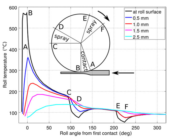
Figure 1.
Typical example of roll temperature in hot rolling.
The main subject of this work is focused on shifting the intensive cooling closer to the rolling gap. The high surface temperature of the roll could potentially yield a high cooling intensity therein.
The question of how to increase the work rolls’ life has been the subject of continuous interest. The paper of Stevens was published in 1971 but it is still very live [1]. The published results of the plant measurement are unique even these days. The most frequent demand of roll cooling designers is to hold the roll temperature low. Some roll producers even recommend a maximum operating temperature of rolls. Solution can be to shift the cooling closer to the rolling gap. The optimal cooling depends on the roll material and is obvious that tension stress in roll surface layer grows with intensity of cooling.
As the plant measurement of cooling intensity is rare the investigators use mostly results of laboratory measurements. Detailed information about the measured HTC is given in [2]. A hollow roll diameter 352 mm, the length of 900 mm and the thickness of the wall of 16 mm is used as a test surface. The rotating test roll is heated by flame on one side and is cooled by row of flat fan nozzles on the opposite side. Embedded thermocouples are used for temperature measurement near the roll surface. Heat transfer coefficients are evaluated from the temperature measurements by the inverse heat conduction task. The results show the HTC distribution both around and along the roll.
A similar laboratory test method with a heated drum was used by Tseng [3,4]. The measured data is used in numerical simulations of stress–strain conditions in the roll. and suggestions are drawn for cooling to extend the roll life. Moderate cooling is recommended with a large roll surface. On the contrary to recommendations of more recent works, Tseng does not recommend intensive cooling near the rolling gap. As the reason he gives the increased thermal cyclic stress reducing the roll life.
Publication [5] relates to the cold rolling, yet interesting results reveal the influence of oil in cooling water. It is shown that even small amount of oil can significantly reduce cooling intensity and this fact is valid for hot rolling as well. This not frequently mentioned effect can be the source of a cooling malfunction.
Clear results describing the influence of position of cooling on the stress in the surface layer is given in [6]. Several numerical simulations show cooling distribution dependent on the surface temperature and its effect on stress conditions. Cooling applied close to the rolling gap is considered as favorable.
Papers [7,8] study thermal stresses in bimetallic rolls. Advanced technology of production and heat treatment of these rolls allow to prepare favorable distribution of residual stresses. Both papers use numerical methods for evaluation of the influence of cooling strategy on stress-strain conditions in both the surface layer and the roll core. Standard cooling is compared to the situation of a cooling failure and the situation of a mill stop when the roll is in a long contact with the hot material. It is shown that abnormality in cooling can cause undesirable increases of the stress in the roll core that can cause a roll breakdown. Both papers present a general recommendation to keep the average roll temperature as low as possible. It should be noticed that in [8] fifty years old plant measurements of Events [1] were used as an input. Plant measurements of this kind are valuable and rare. Paper [9] shows an experimental technique for temperature measurements in hot rolling in which temperature sensors are embedded in inserts, whose surface is aligned perfectly with the roll surface. Two types of sensor were used. The hot rolling results were compared to each other. The tests were done with three levels of slab reduction 10%, 30%, and 50%. The results show the heat flux in the cooling area. Significantly different heat fluxes were observed with each reduction. The cooling section was identical in all three cases considered. A constant water pressure was used. The difference in the heat flux was caused by a different surface temperature at the entrance to the cooling section.
The present paper concentrates on intensifying cooling during the hot rolling. In principle, the proposed method can be employed in other technological processes as well. E.g., in machining namely turning of heat resistant superalloys requires intensive cooling [10]. Although the mainstream of recent developments is towards the use of the CO2 cryogenic cooling, a window remains for appropriate intensive spray cooling. The MQL might see the potential of the proposed method also with the hot stamping [11,12] and the roller burnishing [13]. Another process receiving much attention lately is the spray cooling during the high pressure die casting [14]. The temperature of the die must be swiftly lowered to a uniform predefined value between two consecutive castings, which is realized by a nozzle array mounted on a single computer-controlled robotic arm. Cooling of the die is poor on facets aligned with the jet direction. Such facets could be efficiently cooled by the method described below.
The main topic of the present paper is to redesign the spray cooling of the roll in hot rolling. The water spray is brought closer to the rolling gap while the near-to-normal orientation of the water spray to the surface of the roll is maintained. Thereby, high intensity cooling is achieved.
The introduction section is followed by the section Remote cooling design, in which the new spray cooling method is explained. In the subsequent section Cooling efficiency, the method is subjected to laboratory tests and the obtained cooling intensity is compared with that of a standard flat-fan nozzle. The efficiency of the newly proposed method is confirmed. The CZ patent has been approved by the Czech Patent and Trademark Office. The patent claims are summarized in the section Conclusions.
2. Remote Cooling Design
The high surface temperature at the exit from the rolling gap drops fast due to heat conduction into the roll core. Therein, the high temperature gradient is evident from Figure 1. It is advantageous to extract heat from the hot thin surface layer and avoid heat penetration into the roll core.
Figure 2 shows a typical positioning of the first row of the cooling jets (a). The jet impact is oblique and thus heat transfer coefficient is low. The configuration (b) is not feasible because the cooling header would collide with the wiper blade or another essential technology. The proposed solution uses solid jet nozzles located in the position of standard cooling headers and deflection surfaces–vanes–to transform the solid jet into a flat fan. The deflected flat fan is oriented in a favorable angle and position. The row of the vanes can be mounted directly on the wiper. The shape of the vanes is shown in Figure 3. The complex 3D shape of the vane is designed for the optimal conversion of the solid jet into a flat fan. The trailing edge of the vane can be straight or curved. Further, it can be horizontal or tilted depending on requirements for overlapped spray patterns.
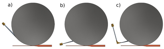
Figure 2.
A cooling section configuration: (a) typical position of the spray, (b) the optimal position, and (c) the new design.
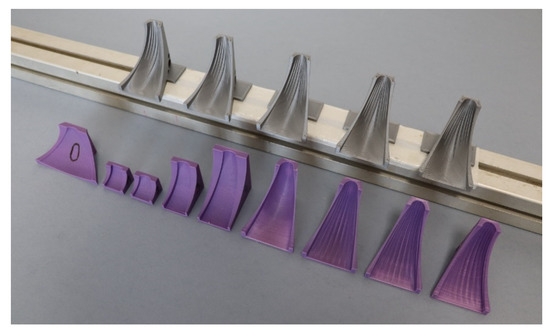
Figure 3.
An example of different vanes used for a conversion of solid jets into flat fans (the size of the gray vane is 50 × 50 × 24 mm3).
3. Cooling Efficiency
The laboratory tests were used to compare the cooling efficiency of the proposed vanes (Figure 2c) and standard flat fan nozzles (Figure 2b) in the respective configurations depicted. A single row of five vanes was considered, as shown at the top of Figure 3. Solid jet nozzles with the orifice diameter of 4 mm and flat fan nozzles were selected to have an identical flow rate at a given pressure. Furthermore, the spray angle of the flat fan nozzle was nearly identical to that produced by the vane (30°). The distance between the solid jet orifice and the vanes was 215 mm. The spray height was 170 mm. The spray height is defined as distance between the orifice of the nozzle/vane and the roll surface. It is not a normal distance, but distance aligned with the jet axis. The tests were done with the feeding pressure of 0.3, 0.5 and 0.8 MPa. The tangential velocity of the roll was 1 m/s. The laboratory configuration of the solid jet nozzles, the deflecting vanes and the roll surface is shown in Figure 4. The photo in Figure 4 (left) was taken with a low water pressure because the view is otherwise obscured by the reflected water. The CAD perspective view on the right in Figure 4 explains what is seen in the photo on the left.
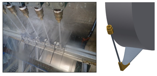
Figure 4.
A photo of the laboratory test (left) and the corresponding CAD view (right); a horizontal row of the solid jet nozzles at the top; the solid jets reaching five vanes; the reflected flat fans exiting from vanes impinging onto the roll surface near the rolling gap.
The experimental equipment used is shown in Figure 5. The essential part is the instrumented segment of the roll with thermocouples (grey in-line spots) recording temperature in depth of 0.4 mm under the surface. The segment is made of austenitic steel 20 mm thick, the remaining surface of the roll is formed by a thin steel sheet. The segment is initially heated up to a uniform temperature. Then, the roll starts rotating. Once the prescribed speed of 1 m/s is reached, the spray cooling is activated. Temperatures from all thermocouples and the instantaneous tangential position of the roll are continuously recorded into the datalogger Ht800. The experiment is followed by solving the inverse heat conduction problem (IHCP), which outputs the reconstructed thermal boundary condition namely surface temperatures and heat transfer coefficients (HTC). The calculated HTC can be plotted as a function of time, the tangential position (defined in Figure 5) and the surface temperature. The experiment and the IHCP are detailed in [9,10,15] respectively.
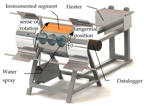
Figure 5.
The roll test bench with water sprays in blue, the segment in orange, the datalogger in brown and the heater in the back. Instrumented segment is hot, and heater is moved out to the rear position.
A comparison of data from the experiment with the flat fan nozzle and the vane is shown in Figure 6. The surface temperature and HTC are plotted as a function of the time. Only five revolutions of the roll are shown to make the plot readable. The cooling intensities are evidently very similar. To show the HTC as a function of the tangential position, the HTC must be averaged over a range of surface temperatures. Figure 7 shows HTC distribution averaged in the range of surface temperature between 220 °C and 50 °C. Averaged values for surface interval ± 100 mm from the impact point are summarized in Table 1.
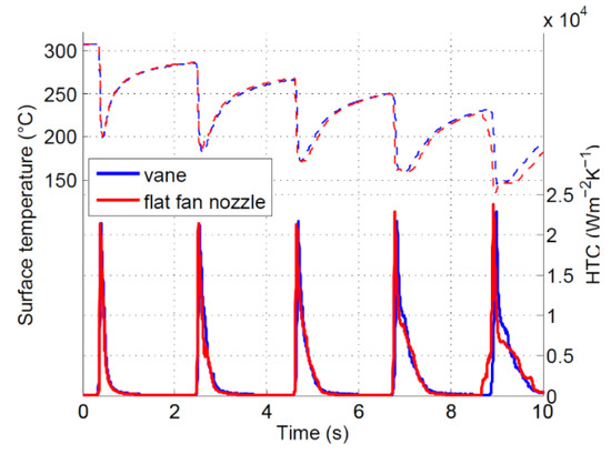
Figure 6.
Surface temperatures and heat transfer coefficient (HTC) for experiments with flat fan nozzles and with deflected jets by vanes, tests with 0.5 MPa feeding pressure.
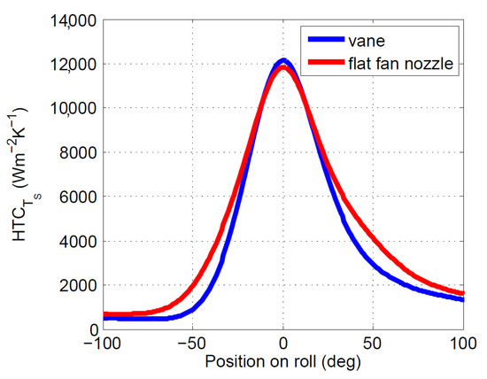
Figure 7.
An average HTC distribution for compared configurations, test pressure 0.5 MPa.

Table 1.
HTC values, averaged between surface temperatures of 220 °C and 50 °C.
4. Conclusions
The new method of cooling of rolls in the hot rolling is introduced with the applicability to other processes. By using specially shaped vanes, the spraying jet is emerging from locations that are otherwise unthinkable with the standard cooling instruments. It allows the cooling jet to hit the roll surface at the optimal angle near the rolling gap so that the cooling intensity is maximized.
The proposed method consists of solid jet nozzles mounted to a common water supply infrastructure and the vanes. The latter converts the cylindrical jet into a flat fan, which is redirected to the optimal spot on the roll surface. The laboratory experiments confirmed that cooling intensity of the reflected jet is similar to that of the flat fan nozzle. However, the latter is mounted in the position impossible in the plant. Next, the reflected jet does not lose the kinetic energy in comparison to the jet produced by the flat nozzle with the identical feeding pressure and flow rate. The differences in the cooling intensities are small. The average HTC of the reflected jet is lower by 8% with the water pressure of 0.3 MPa. It becomes nearly identical with the water pressure of 0.8 MPa It is estimated by numerical methods that shifting the cooled area from a circumferential position of 90° close to the rolling gap to the position 45° can increase the cooling intensity by 27%. This conclusion is valid for identical HTC and appropriate surface temperatures behind the rolling gap.
The authors of this communication give laboratory-verified information for the plant experts and designers. The effective cooling can be shifted closer to the rolling gap. One row of solid jet nozzles can be added to the existing cooling header. The vanes can be fixed to the wiper at the exit side of a rolling mill. Thus, a collision with standard cooling instruments is prevented.
5. Patents
The national patent has been approved in the Czech Republic.
Author Contributions
Conceptualization, M.R. and J.B.; methodology, P.K.; software, J.B.; validation, M.R., J.B. and P.K.; formal analysis, M.R.; investigation, J.B.; resources, M.R.; data curation, J.B.; writing—original draft preparation, M.R. and J.B.; writing—review and editing, M.R.; visualization, J.B.; supervision, M.R.; project administration, P.K.; funding acquisition, M.R. All authors have read and agreed to the published version of the manuscript.
Funding
This research received no external funding.
Institutional Review Board Statement
Not applicable.
Informed Consent Statement
Not applicable.
Data Availability Statement
Not applicable.
Acknowledgments
Laboratory work presented in this paper was supported by the internal grant of the Brno University of Technology focused on specific research and development No. FSI-S-20-6478.
Conflicts of Interest
The authors declare no conflict of interest.
References
- Stevens, P.G.; Ivens, K.P.; Harper, P. Increasing work-roll life by improved roll-cooling practice. J. Iron Steel Inst. 1971, 209, 1–11. [Google Scholar]
- Solimani, M.R.; Barbosa, R.A.; Leocadio Junior, H. Analysis of heat transfer of work roll cooling in hot rolling. Technol. Metal. Mater. Min. 2013, 10, 191–199. [Google Scholar] [CrossRef][Green Version]
- Tseng, A.A.; Lin, F.; Gunderia, A.; Ni, D. Roll cooling and its relationship to roll life. Metall. Trans. A 1989, 20, 2305–2320. [Google Scholar] [CrossRef]
- Tseng, A.A.; Gunderia, A.; Sun, P. Cooling of roll strip in steel rolling. Steel Res. 1991, 62, 207–215. [Google Scholar] [CrossRef]
- Davenport, C.J.; Smith, J.K. Improving roll cooling on cold tandem mills. Steel Times Int. 2008, 32, 17–19. [Google Scholar]
- Saha, J.; Kundu, S.; Chandra, S.; Sinha, S.; Singhal, U.; Das, A.; Saha, J. Mathematical modelling of roll cooling and roll surface stress. ISIJ Int. 2005, 45, 1641–1650. [Google Scholar] [CrossRef]
- Hu, K.; Xia, Y.; Zhu, F. Evaluation of thermal breakage in bimetallic work roll considering heat treated residual stress combined with thermal stress during hot rolling. Steel Res. Int. 2018, 89, 1700368. [Google Scholar] [CrossRef]
- Hu, K.; Zhu, F.; Chen, J.; Noda, N.-A.; Han, W.; Sano, Y. Simulation of thermal stress and fatigue life prediction of high speed steel work roll during hot rolling considering the initial residual stress. Metals 2019, 9, 966. [Google Scholar] [CrossRef]
- Horsky, J.; Raudensky, M.; Pohanka, M. Experimental study of heat transfer in hot rolling and continuous casting. Mater. Sci. Forum 2004, 473, 347–354. [Google Scholar]
- Amigo, F.J.; Urbikain, G.; Pereira, O.; Fernandez-Lucio, P.; Fernandez-Valdivielso, A.; Lopez de Lacalle, L.N. Combination of high feed turning with cryogenic cooling on Haynes 263 and Inconel 718 superalloys. J. Manuf. Process. 2020, 58, 208–222. [Google Scholar] [CrossRef]
- Lin, T.; Song, H.-W.; Zhang, S.-H.; Cheng, M.; Liu, W.-J. Cooling Systems Design in Hot Stamping Tools by a Thermal-Fluid-Mechanical Coupled Approach. Adv. Mech. Eng. 2015, 2014, 545727. [Google Scholar] [CrossRef]
- Nurnberger, F.; Diekamp, M.; Moritz, J.; Wolf, L.; Hubner, S.; Behrens, B.-A. Spray cooling of Early Extracted Hot Stamped Parts. In Proceedings of the TMS 2014: 143rd Annual Meeting & Exhibition, San Diego, CA, USA, 16–20 February 2014; pp. 983–990. [Google Scholar]
- Rodriguez, A.; Lopez de Lacalle, L.N.; Pereira, O.; Fernandez, A.; Ayesta, I. Isotropic finishing of austempered iron casting cylindrical parts by roller burnishing. Int. J. Adv. Manuf. Technol. 2020, 110, 753–761. [Google Scholar] [CrossRef] [PubMed]
- Yamagata, H.; Kimura, T. Effect of spray-cooling rate on the die-life of an HPDC die. Adv. Mater. Process. Technol. 2017, 3, 274–285. [Google Scholar] [CrossRef]
- Ondrouskova, J.; Pohanka, M.; Vervaet, B. Heat-flux computation from measured-temperature histories during hot rolling. Mater. Technol. 2013, 47, 85–87. [Google Scholar]
Publisher’s Note: MDPI stays neutral with regard to jurisdictional claims in published maps and institutional affiliations. |
© 2021 by the authors. Licensee MDPI, Basel, Switzerland. This article is an open access article distributed under the terms and conditions of the Creative Commons Attribution (CC BY) license (https://creativecommons.org/licenses/by/4.0/).