1. Introduction
Cold gas dynamic spray (CGDS), or less formally, cold spray, is a solid-state materials consolidation and processing technology that utilizes particulate feedstock that is transported via a heated carrier gas stream until exiting a de Laval nozzle and then supersonically impacting a substrate [
1]. CGDS processing was initially conceptualized as a tool for achieving coatings with unique and application-specific properties [
2]. Following the accidental discovery of CGDS processing in the Soviet Union during the 1980s, the solid-state technological process was adopted by the remanufacturing and repair [
3] sector as well as the additive manufacturing (AM) community [
4]. Supersonically accelerated particles are deposited onto a substrate with high strain rates to consolidate material(s) in a layer-by-layer fashion until a thickness or geometry is achieved [
5]. Therefore, successful CGDS processing and materials consolidation depend upon particle-substrate and particle-particle metallurgical and mechanical bonding. CGDS processing parameters vary from the nozzle type to the selection of powder composition and gas source. Typically, inert gases are used, such as helium or nitrogen [
6], but compressed air has been employed as well [
7]. Feedstock powder for CGDS processing typically has a diameter range from approximately 5 to 100 µm. These particles generally achieve velocities between 300 and 1200 m/s.
Recent decades have seen a transitioning of CGDS from governmental or national labs and academia to the commercial and industrial sector due to its extreme flexibility in upscale robotics and material permutations [
8,
9,
10]. In any case, advanced CGDS processing development continues to emerge and evolve through unique applications by way of invoking a process-structure-property-performance perspective [
11] or a through-process framework [
12]. Consequently, the resultant materials consolidated via CGDS have reportedly achieved appreciable technological readiness levels, scientific robustness, and economic viability [
13]. In turn, one of the aims of the present work was to contribute to the continued compilation of contemporary findings surrounding CGDS processing with reverence to prior academic work via the lens of a novel exploratory study on substrate near-surface and subsurface microstructural evolution following CGDS deposition and thermal postprocessing.
With the aforementioned in mind, the present work detailed herein took a precursory and exploratory approach to the inspection of CGDS-based material surface modification processing as a potentially suitable pathway to the procurement of improved near-surface properties regarding fracture or impact toughness and strength relative to the original surface state of the substrate material. This work was motivated by the aluminum automotive industry, which seeks to produce cost-effective cast components that achieve improved mechanical properties, i.e., properties typically associated with premium aluminum alloys such as A201.
Premium aluminum alloys such as A201 are generally sought after due to their excellent toughness and high-temperature properties. The cost of A201, the difficulties, and the human hazards associated with processing such an alloy have motivated engineers within the automotive sector to select cost-effective alternatives. Material classes such as steel systems are utilized in many applications where toughness is critical, even though steel increases the overall vehicular mass and lowers fuel efficiency. To avoid the use of steel (as well as the complications that arise from processing A201 alloyed components), previous research has developed a new aluminum alloy known as NASA-427 for automotive applications where high impact toughness is a critical property. Though the approach of novel alloy design warrants attention and continued consideration within the automotive industry, the improved fuel efficiency achieved when using NASA-427 instead of steel, the processing capacity of NASA-427, and the mechanical properties of NASA-427 do not address the problem of being prohibitively costly when compared with typical, cost-effective aluminum alloys. Thus, if one were to approach the issue of employing a lightweight aluminum material for impact-critical automotive applications with the minimal economic expense and increased processing compliance, then sophisticated chemical or mechanical surface modification of common alloys, such as A356, A365, and E357, would serve as an advanced manufacturing solution. Noted throughout the present manuscript, A365 was selected as the high-pressure diecast (HPDC) aluminum alloy of relevance herein due to its pervasiveness in aluminum foundries.
That said, this work also takes a precursory scientific look into current surface modification processing techniques. In doing so, the fundamentally applied scientific exploration presented herein aims to provide automotive materials and materials processing engineers with structure-processing-properties insights. In turn, such insights can subsequently be linked to common castable aluminum alloys and their application-specific performances as a function of the surface modification method utilized. Accordingly, this exploratory investigation characterizes the microstructural, micromechanical, and microchemical behaviors as a function of the CGDS surface modification techniques considered herein. Moreover, the characterization and discussion reported herein provide a direction for future research and development surrounding the application of CGDS surface modification techniques for application-specific performance requirements in the automotive sector.
Accordingly, the CGDS surface modification process must show significant promise for achieving an improvement in such properties and be cost-effective and easily adaptable in a typical foundry or manufacturing downstream. Diffusion of foreign material from the CGDS coating(s) and into the substrate was investigated with various coating metals. The diffusion process was facilitated in the solution treatment step for the given substrate aluminum to strengthen the parts’ subsurface region while maintaining standard heat treatments employed in the industry. This research aimed to provide a platform for further research into the practical effects of CGDS coating and thermal postprocessing on the coating-substrate’s regional microstructural and microchemical properties.
Historically, CGDS thermal postprocessing work has been done on a self-similar substrate and feedstock combination(s), simplifying thermal processing optimization. For example, Rokni et al. not only recognized the fact that the powders utilized in [
14] were sourced from precipitation-hardenable aluminum alloy compositions (Al 7075 in particular) and identified that the substrate used was wrought Al 7075, thus capturing feedstock-substrate self-similarity.
Thermal postprocessing remains invaluable as a means of enhancing deposited material performance. Much more research and development must be explored for different feedstock-substrate material combinations to properly understand the unique consequences stemming from multi-material systems adhered to one another via CGDS. At the same time, Rokni et al. also reconsidered and recorded thermal postprocessing induced relations for Al 7075 feedstock particulates sprayed onto an Al 7075-T6 substrate in [
15]. However, upon closer inspection of the published research of Rokni et al., their work mainly focused upon heat treating bulk CGDS materials detached from a sacrificial substrate, thus limiting the ability to compare to the analysis of Rokni et al. Such limited comparability stems from the fact that the current manuscript is concerned with subsurface and interfacial substrate-coating property and structure evolution, rather than bulk CGDS material consolidation properties, as had been of considerable interest to Rokni et al.
Work has been conducted to improve the deposited material and primarily has been done with indifference to a sacrificial substrate. Prior work has also shown that CGDS can improve impact resistance and fracture toughness, among other mechanical properties, in the bulk material substrate systems from CGDS processing for a select set of powder–substrate material combinations. Jafarlou et al. demonstrated improved mechanical properties of an AM 15-5 precipitation-hardenable stainless steel via thermal processing coupled with a CGDS-based consolidation of a thin chrome-carbide and nickel coating [
16]. Furthermore, Yang et al. revealed that the CGDS consolidation of Al 5052 and other Al-based coatings enhanced the “fatigue crack propagation performance” of a steel-based substrate [
17].
Enhancements in fatigue or impact behavior improvements, wear resistance [
18], tribological performance [
19], hardness [
20], and corrosion resistance [
21] can all also follow from properly engineered and processed CGDS consolidations deposited onto target substrate specimens. Research by Huang et al. demonstrated a hypothesized balance between improved wear and corrosion resistance, room temperature ductility, and “good vibration damping properties,” as articulated in [
22].
Implementation of CGDS processing to deposit a strengthening or toughening agent upon a target substrate or base material has been shown to maintain a degree of potential and promise. A combination of efficient feedstock use, low-temperature application, and focused mechanical property manipulation will prove to be a powerful technique for the wider manufacturing industry as a more refined understanding emerges via highly nuanced and targeted subsequent studies. Further expanding CGDS technology and research has industrial implications ranging from the automotive sector to the aerospace industry. A hypothetical example could be of known weak points in auto frames. Suppose a localized section is prone to fatigue failure or requires more ductility for safety in crumple zones. In that case, CGDS could be employed to apply a toughening or strengthening component to targeted locations rather than an entire frame to improve mechanical properties. Work must be conducted to prove this approach’s viability and thereafter the material combinations that would provide such mechanical improvements.
2. Experimentation, Materials, and Methods
The present research focuses on surface and subsurface microstructural development and evolution due to surface modification of structural alloys. To this end, a coating was deposited to the base material, and a heat treatment was applied to facilitate diffusion and, consequently, enhance subsurface properties and microstructures. The proposed materials to coat aluminum substrates are also known for alloying or strengthening enhancement mechanisms. The coating materials include copper, nickel, titanium, and zinc; however, only the first three pure metals could be utilized during the current work. The methods of electroplating, electroless plating, hot-dip galvanizing, and CGDS were considered and tested in an exploratory fashion. CGDS was determined to be the best in terms of continuity of the coating and lab-scale production reproducibility.
Copper was selected as it is the primary alloying constituent currently used in aerospace applications for these desired mechanical properties [
23]. Nickel was chosen for the potential benefits found in nickel aluminide materials [
24]. Nickel aluminide has excellent high-temperature properties, but processing at lower temperatures is complicated due to the material’s brittleness [
25]. Titanium was selected due to Ti’s use in tool steels and Ti’s known ability to refine aluminum’s grain structure [
26]. Furthermore, titanium nitride increases various mechanical properties, including impact strength, among other properties [
27].
Subsize, cost-effective aluminum alloy substrates composed of A365 (see
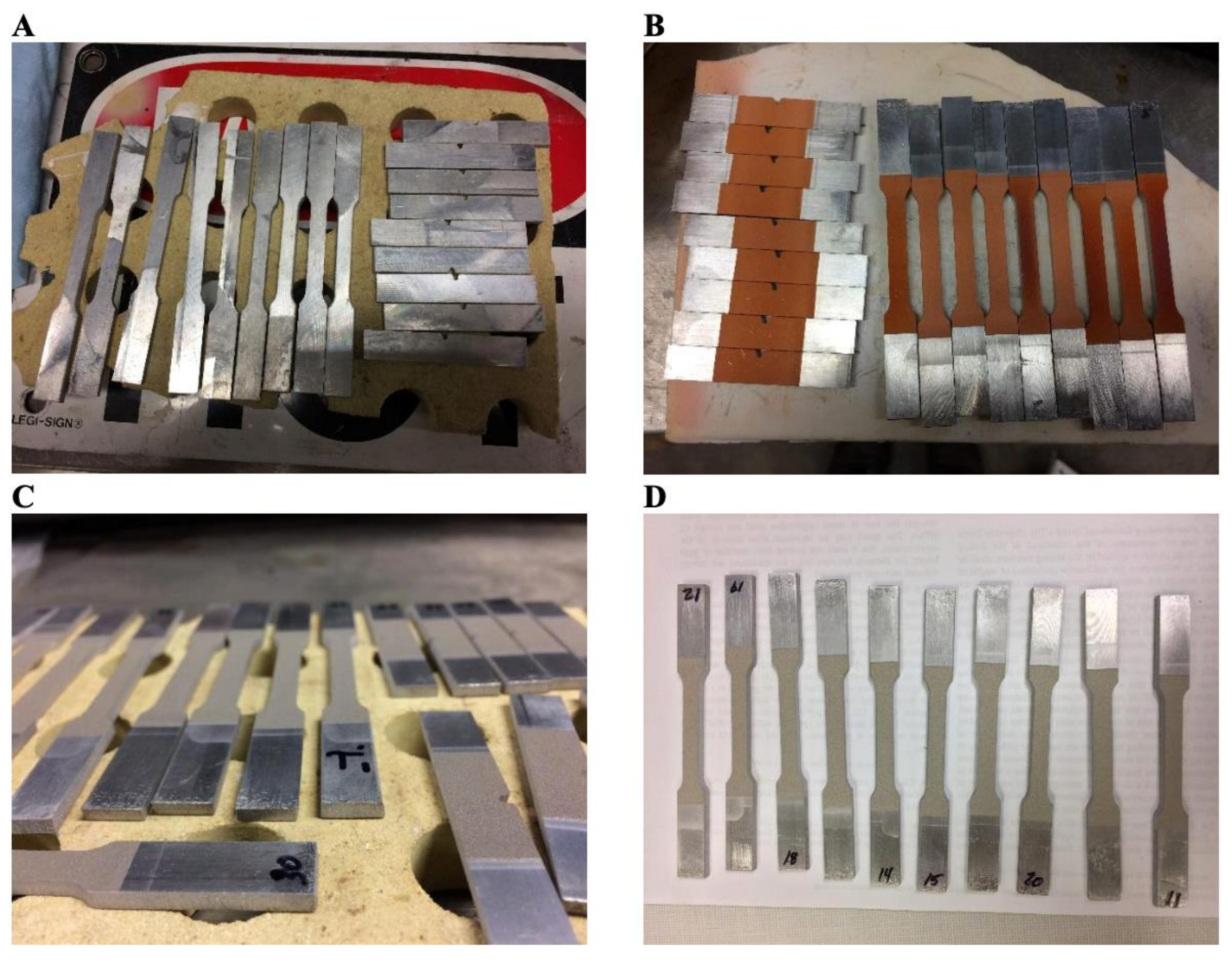
Table 1) and exposed to CGDS surface modification were produced via waterjet cutting from stock HPDC A365 aluminum donated by the aluminum division of Rio Tinto (Montreal, QC, Canada). Pre-waterjet-cut HPDC-A365 plates were approximately 229 mm by 76 mm by 3 mm in thickness. Plates were faced in a HAAS Mini Mill (Haas Automation, Inc., Oxnard, CA, USA) to a 2.5 mm uniform thickness (before waterjet cutting) in the Worcester Polytechnic Institute Machine Shops (Worcester, MA, USA). Parts were waterjet cut by Hydracadabra (Amesbury, MA, USA) at Arc Technologies, Inc., and now titled ARC Technologies, a Hexcel Company (Amesbury, MA, USA). The Applied Research Lab conducted CGDS processing of nickel, titanium, and copper feedstocks at Pennsylvania State University (State College, PA, USA). Cut samples before CGDS were wire brushed and cleaned with isopropyl alcohol. Accordingly,
Figure 1 presents digital images of the waterjet-cut HPDC A365 substrate/base material in the as-cast condition (see
Figure 1A) and as-CGDS-processed conditions too.
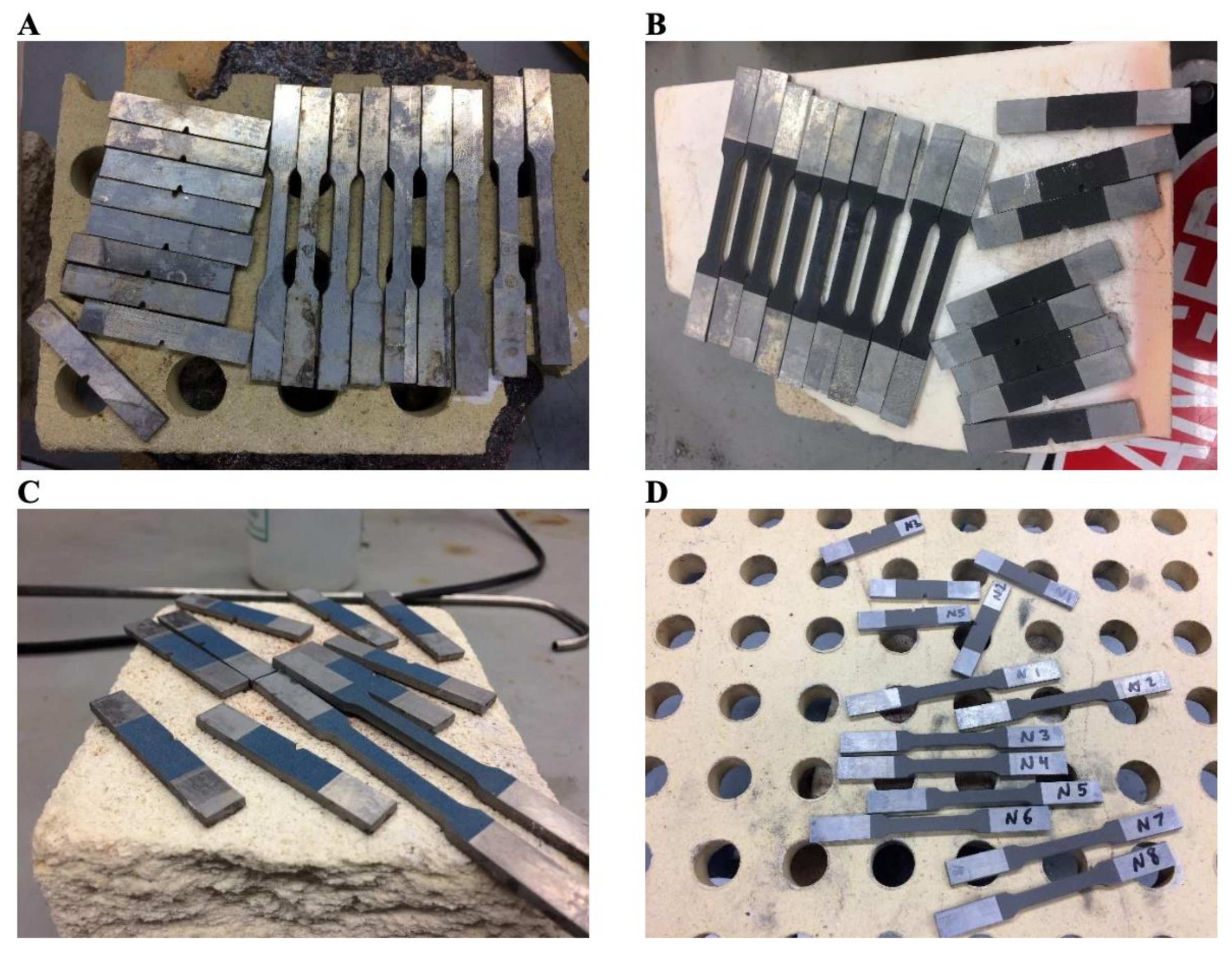
Solution treatments were conducted utilizing the parameters recommended by the aluminum division of Rio Tinto. A furnace was run at 500 °C for several hours to regulate and stabilize the system before applying the solution treatment. Samples were placed in the furnace and then allowed to sit until the associated thermocouples read 500 °C once again. Once the temperature was reached, a timer was set for 80 min. After 80 min of hold time, the solution-treated specimens were removed and cooled by forced-air cooling. In turn, the following digital images were recorded, as shown in
Figure 2. Most of the dramatic events surrounding diffusion-based chemical interactivity between the deposited CGDS coating and substrate material would have occurred during the solution treatment step due to the very high temperature relative to the melting point of the substrate’s aluminum matrix. Note that T6 heat treatments, following solution treating, were also performed via the following conditions and parameters: natural, room temperature aging for 24 h, followed by artificial aging in a furnace that was regulated once again at 170 °C for several hours before introducing the sample, and finally holding the sample at 170 °C for 150 min.
CGDS deposition of nickel, titanium, and copper feedstocks was conducted at the Applied Research Lab at Pennsylvania State University (State College, PA, USA) using proprietary and undisclosed processing procedures. The Applied Research Lab utilized nitrogen as the carrier gas for copper and nickel and helium for titanium. Furthermore, a VRC GEN III CGDS processing system (VRC Metal Systems, Box Elder, SD, USA) was utilized to deposit all three pure metal particulate feedstocks considered herein. The coatings’ goal thickness was 100 µm to provide sufficient diffusing material and achieve comparable coating thicknesses in light of the typical thickness ranges associated with alternative surface treatments such as electroless Ni plating. Unfortunately, only two broad face CGDS coating was deposited for each substrate sample, rather than all of the broad faces of the waterjet cut substrate specimens, thus preventing accurate macro-mechanical testing of the bimetallic systems considered.
CGDS-processed samples were compression mounted in a phenolic thermosetting resin via a Buehler Simplimet 4000 (Lake Bluff, IL, USA). According to standard metallographic practices, grinding and polishing was carried out using a Buehler Ecomet 300 grinder–polisher. Optical microscopy was performed using an inverted metallurgical microscope equipped with an Olympus Microscope Camera DP73 (Olympus Corporation, Shinjuku City, Tokyo, Japan). Energy-dispersive X-ray spectroscopy (EDS) was performed by way of an Oxford Instruments X-MaxN detector (Abingdon, Oxfordshire, UK) coupled with a JEOL JSM-7000F field emission SEM (Akishima, Tokyo, Japan).
Three powder suppliers were identified as being able to accommodate the small-batch orders. The commercially pure Ti feedstock powder was obtained from Accushape, Inc. (Portland, OR, USA). Accordingly, the Ti feedstock was the only feedstock that was not produced via atomization-based approaches herein; thus, it yielded sponge-like or foam-like morphologies relative to the virtually spherical copper and nickel feedstock powders. Specifically, the gas-atomized nickel powder, which maintained a 270-mesh particle size distribution or condition, was produced by Praxair S.T. Technology, Inc. (Praxair, Inc., Danbury, CT, USA) with a product I.D. of NI-914-1. Unlike the atomized Ni powder, which was gas-atomized in an inert gas, the Cu powder was atomized using air (rather than an inert gas) and also underwent annealing by ACuPowder International, LLC (Union, NJ, USA), which now resides under the umbrella of Kymera International (Research Triangle Park, Durham, NC, USA).
3. Results and Discussion
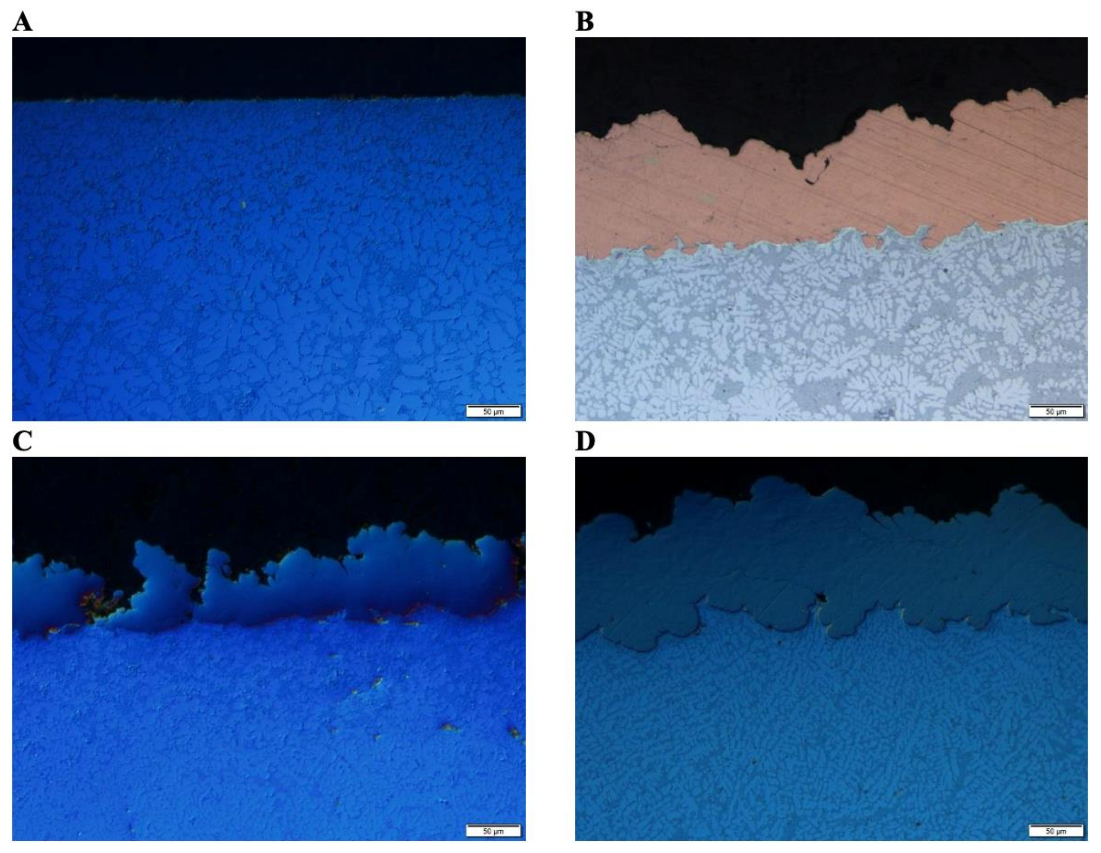
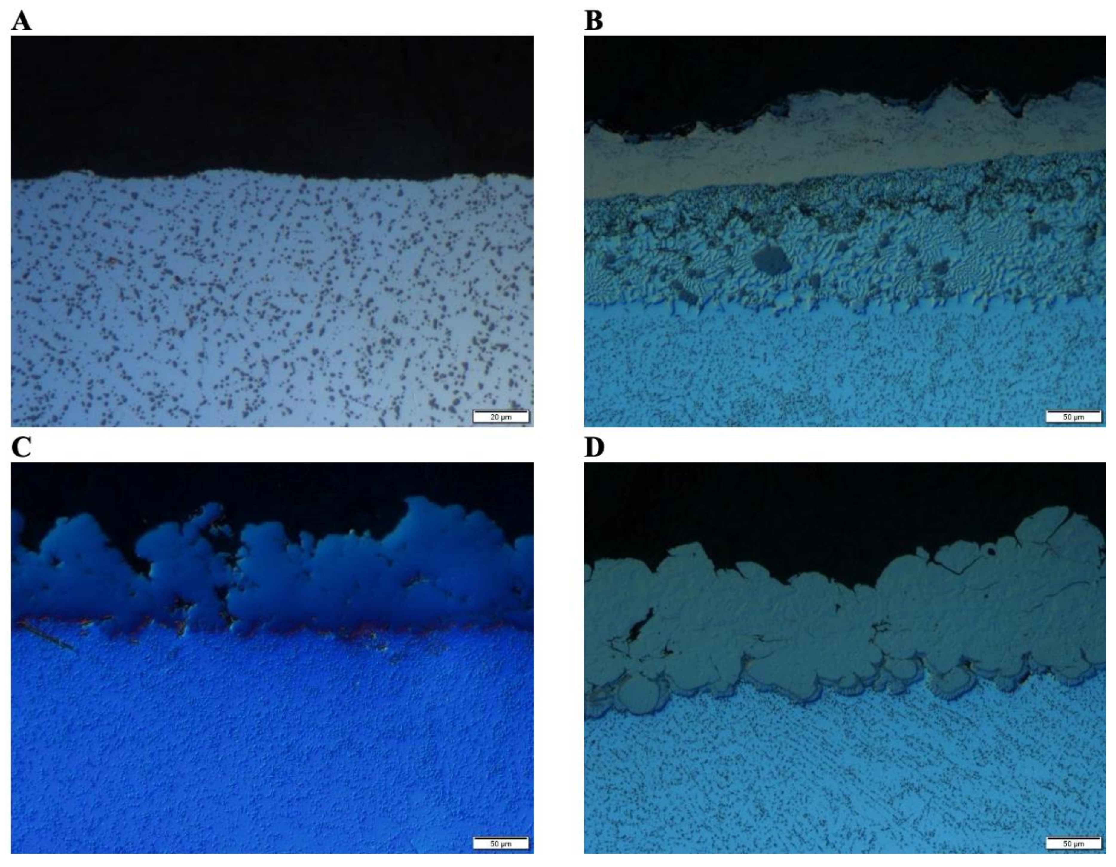
Figure 3, in part, presents cross-sectional optical micrographs of the cast A365 substrate, as shown in
Figure 3A, and the coated substrates. A secondary microstructural phase grain size gradient can be observed in
Figure 3A. The A365 material yields a more refined grain size distribution towards the casting’s surface and a coarser dendritic microstructure away from the casting’s surface. The cross-sectionally oriented microstructure of the A365 was consistent with typical microstructures previously recorded for nominal A365 castings [
28]. Specifically, the microstructure of the as-cast A365 system presented in
Figure 3A was found to be consistent with the microstructure shown in [
29], which noted “primary eutectic α-Al dendrite grains with needle-like or acicular eutectic Si particles”, which adequately captured the observations recorded herein.
As for
Figure 3B, a much less pronounced near-surface and subsurface microstructurally dendritic grain-scale texture was present within the copper-coated A365 substrate compared with the microstructure presented in
Figure 3A. In contrast, the microstructural texture affiliated with the nickel coated A365 substrate, in
Figure 3D, was more pronounced than that of the copper specimen in
Figure 3B and less gradually transitional than the microstructural texture found in
Figure 3A. At the same time, it is also interesting to note that the copper samples resulted in the HPDC A365 substrate material, near the coated surface and coating-substrate interface, hydrodynamically flowing within the coating, and vice versa, via Kelvin-Helmholtz interfacial instabilities [
30]. Nickel and titanium samples, however, did not achieve the same degree of interfacial intermixing between the substrate and deposited material.
The subsurface microstructure associated with the A365 material shown in
Figure 3A, relative to the CGDS surface-modified A365 substrate materials shown in
Figure 3B–D, raises interesting questions surrounding the degree of substrate material plastic deformation induced grain refinement and substrate erosion. From the micrograph of the substrate system, shown in
Figure 3C, following CGDS processing with pure Ti feedstock, limited substrate erosion was observed. Said observation follows from the fact that the microstructural grain size gradient noted initially in
Figure 3A remains and would have been retained if significant erosion had occurred since the as-cast microstructural texture’s location followed within such a casting. As such, the Ti-based CGDS processing explored in the present work retained the fine grain size distribution towards the casting’s surface and a coarser dendritic microstructure moving away from the Ti-A365 interface.
Based on
Figure 3, the consolidated Ti CGDS coating’s deposited particulates achieved insufficient particulate-particulate bonding with one another in the as-deposited state. In contrast, the nickel and copper deposits were relatively thinner. It is also evident that there are limited mechanical interlocking and interfacial mixing within the Ti-A365 system when compared with the other coating-substrate material combinations. Consequently, the Ti CGDS coatings’ remarkable preservation of the as-cast subsurface microstructural features suggests that the mechanical properties, such as impact and fracture toughness, of the layered Ti-A365 system can be retained and enhanced when CGDS processing parameters are optimized. Furthermore, microstructural gradient preservation would likely be consistent with the work of Shivkumar et al. Both parties noted that finer grain sizes near cast aluminum surfaces would yield more desirable impact energies and fracture toughness’s in proportion with the silicon phase spacing between grains [
31].
There are two possible culprits related to the coarser grain size distribution in the subsurface region of the Cu-based CGDS-processed material relative to the Ni CGDS coated A365 system. One potential explanation surrounds the possibility that the Cu powders eroded the alloyed aluminum substrate to a much greater extent than that of the commercially pure Ni feedstock. The tendency for a material to be removed via erosive peening effects has become commonly understood by those in the field as more prominent when the particulate utilized maintains higher hardness than the substrate. Based on the work by Wei et al., which found that gas-atomized Ni powder had a hardness of 165.3 HVN [
32], and the work of Sundberg et al., which reported a gas-atomized Cu powder hardness of 123 HVN [
33], it stands to reason that rapidly solidified particulate strength was not solely responsible for the observed difference in substrate erosion. Beyond the difference in particulate strength between the inertly atomized Ni powder and the air-atomized Cu, the use of air-atomization for copper production can result in copper oxide film thickness of exceptional magnitude when compared with inertly atomized copper powder.
The second so-to-speak culprit follows from appreciable consideration of the Cu and Ni powders’ surface oxidation state as far as CGDS processing implications are concerned. Nickel forms a passivating oxide-hydroxide layer(s) on the surface, as detailed by others [
34,
35,
36]. In contrast, gas-atomized Cu has been found to form a non-passivating Cu
2O surface film, as discussed by Sousa et al. in [
37], which can range from at least 5 to 20 nm following inert gas-atomization and can continue to thicken over time [
38]. Recent work by Razavinpar et al. found that gas-atomized, pure Cu, particulate surface oxide film thicknesses doubled after only “2 months of exposure to atmospheric conditions” [
39]. Coupling such an understanding of copper surface film formation and thickness, in comparison with the passivated nature and much smaller thickness of Ni powder surface films, with work by Shikalov et al. surrounding supersonic microparticle deposition upon erodible substrate materials [
40], unveils a potential framework for understanding how a softer material, i.e., Cu, could have resulted in such pronounced erosion of the cast substrate relative to Ni.
Shikalov et al. discussed how substrate erosion during CGDS processing would continue to occur until a particular threshold is crossed concerning the number of particles impacting the substrate surface per unit area depending on deposition parameters. A combination of deficient impacting particles to break substrate oxides, the thick oxide shells, and not meeting critical velocities may explain copper’s poor adhesion. It stands to reason that the long-term storage of the Cu feedstock before its use herein introduced a greater degree of substrate removal via erosion before mechanical and metallurgical bonding between the substrate and a portion of the particles that successfully surpassed the 1.3-times the critical impact velocity threshold of proposed by Tiamiyu et al. in [
41].
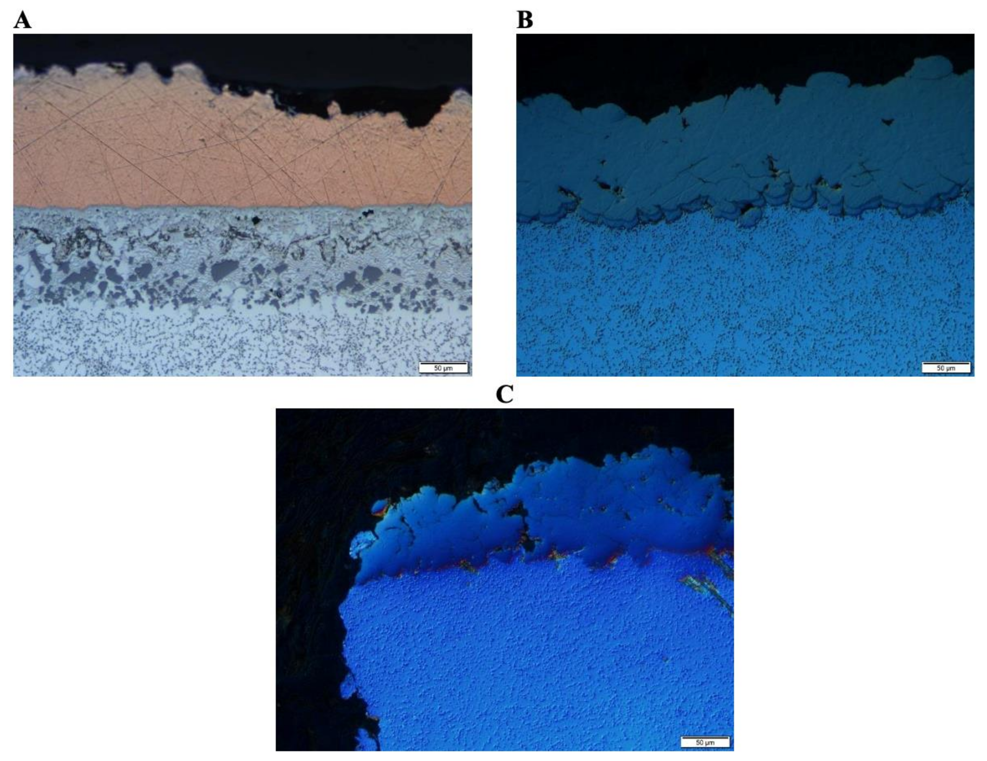
The microstructures of the coated substrates after solution treating are shown in
Figure 4. In each of the CGDS-processed HPDC Al 365 substrates, solution treatments resulted in the subsurface Al 365 microstructure’s thermal recrystallization. The dendritic texture initially present in the as-cast material, and partially present in the Ni and Ti samples, was no longer present in any subsurface(s) recorded in
Figure 4. The recrystallized subsurface microstructures of the three coated specimens were unique to the feedstock metal and processing parameters utilized during CGDS. The mechanically induced subsurface microstructural modification that followed from CGDS processing was modified further via thermally induced chemical activity.
The solution-treated Cu samples substrate’s micrograph reveals a diverse intermetallic-rich region that formed secondary phases and even precipitates in the substrate’s diffusion zone followed by a relatively precipitate-free band of Cu-enriched face-centered cubic (FCC) alpha-Al. Following the substrate diffusion zone, a conventional, solution treated, A3xx microstructure that houses standard secondary intermetallic phases between dendritic boundaries in the HPDC A365 can be seen; this microstructure can also be seen in the respective and comparable regions of relevance within
Figure 4B,C.
Though the secondary phases within the HPDC A365 coated and thermally processed systems captured in
Figure 4B,C are comparable with that of
Figure 5A, the degree of diffusion of Ti and Ni into the HPDC A365 material following solution treating was much more reserved than that presented in
Figure 4A for Cu. Copper deposited samples after thermal processing showed more porosity near the interface, likely due to diffusion since no porosity was present immediately after consolidation. Conversely, the Ni and Ti deposits demonstrated more porosity in the coating(s) and little porosity in the substrate nearest the interface.
The uncoated A365-T6 microstructure captured in
Figure 5A was found to maintain a uniquely discernable microstructure compared with the as-cast A365 shown in
Figure 3A. The morphology of the eutectic silicon-rich regions, which were found between the dendritic primary eutectic FCC Al matrix phases in the as-cast substrate material were shown to have undergone rounding, spheroidization, and ripening in a manner comparable with that observed by Ma et al. [
42]. While Ma et al. also noted the persistent presence of Fe-rich intermetallics along grain boundaries following solution heat-treating, the Mn, Si, and Mg content of the HPDC A365 system under consideration herein promotes the formation of alpha-Fe (Al
15(Fe, Mn)
3Si
2) script-like precipitates in place of needle-like beta-Fe (Al
5FeSi) phases [
43]. The presence of alpha-Fe intermetallics in the as-cast and uncoated A365-T6 systems was consistent with the work of Liu et al., which also had alpha-Al grains, “fiber or short rod-like” eutectic Si-based phases, and alpha-Fe intermetallics [
28].
One may note that the subsurface microstructural regions within the precipitation-hardened HPDC A365 component no longer house the same degree of variability concerning the distance away from the surface that the as-cast A365 metal maintained. Such microscopy-based comparative evaluation of the subsurface microstructures of interest was also consistent with several studies, cited hereafter, that also identified coarser and more homogenous morphology throughout T6 postprocessed Al-Si-Mg-Mn castings [
28,
44,
45,
46].
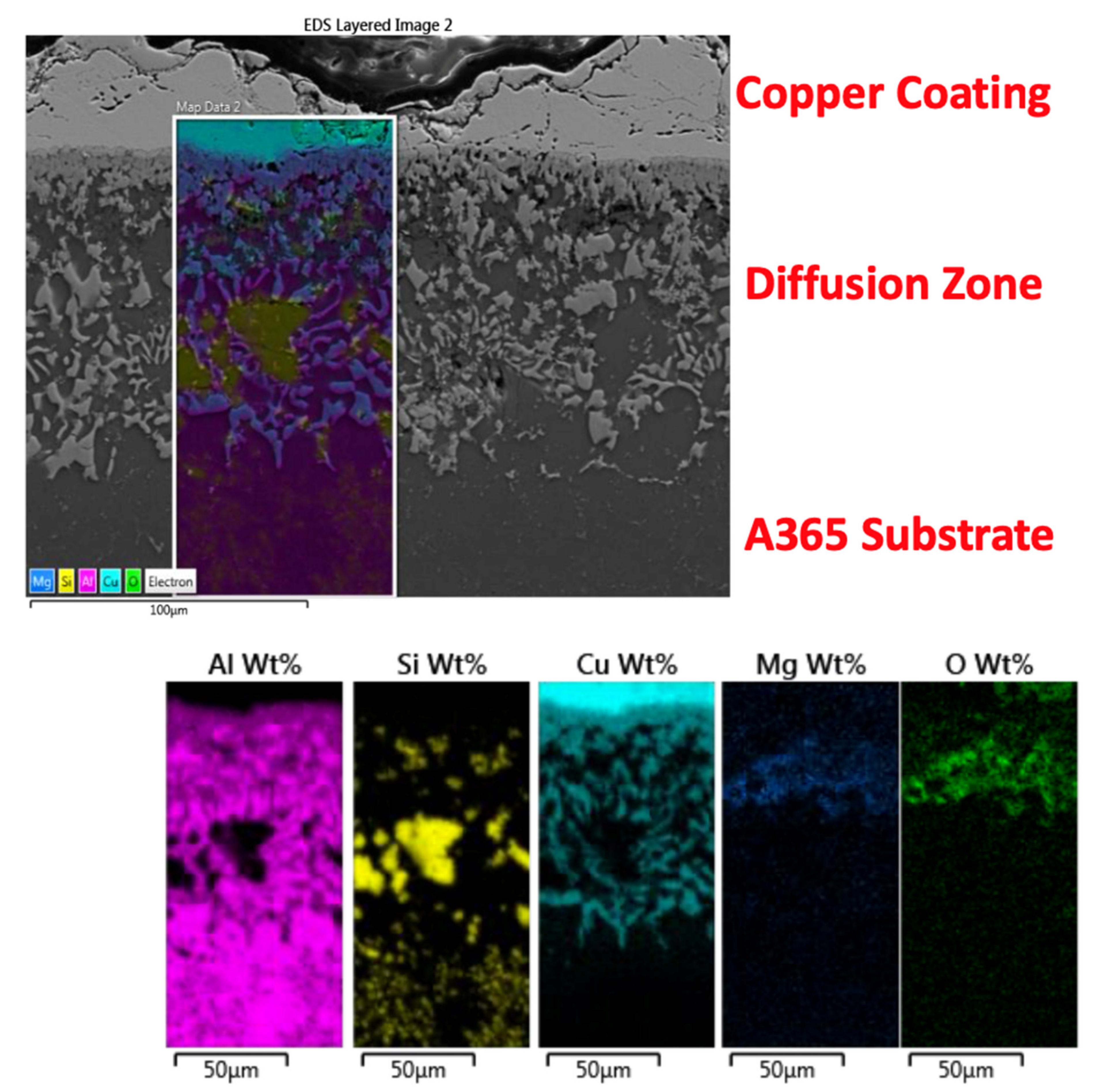
Copper cold spray coatings consolidated upon HPDC A365 underwent a T6 treatment cycle. The first layer is composed of the copper coating, the next distinct layer is the diffusion zone, and the final layer is the A365 substrate. EDS mapping shows the contents of each of these regions. The copper coating is dense with little to no porosity. The high impact of cold spray closed all gaps and provided an excellent coating method in this regard. Black streaks can be seen towards the top of the image, and these are bands of copper oxide.
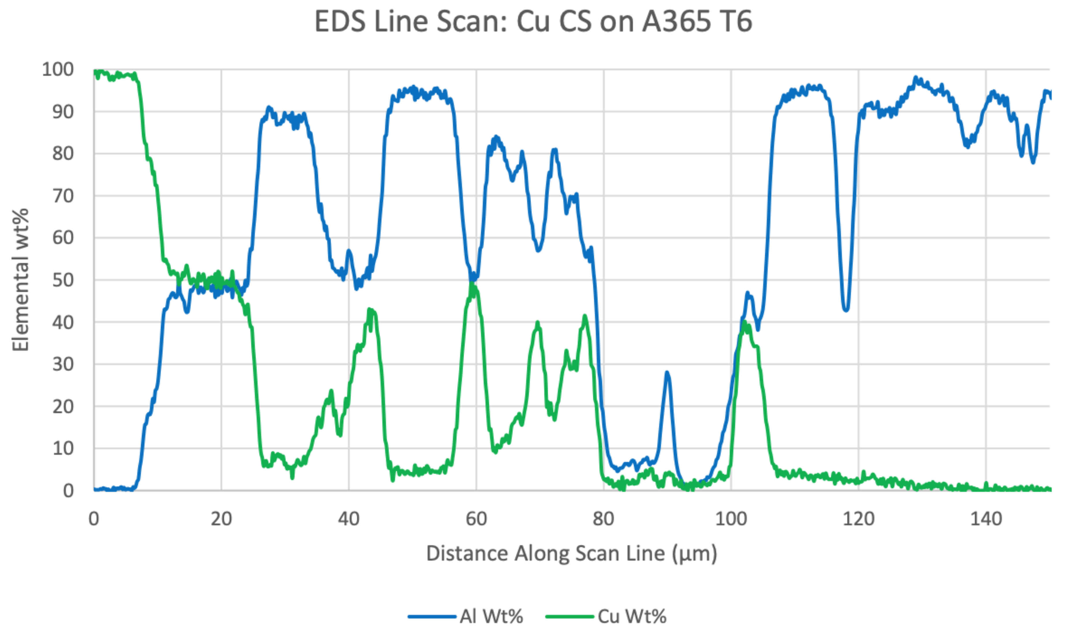
A thin layer between the copper coating and the aluminum has developed, determined to be a continuous aluminum-copper phase, which is expected. According to EDS line scans in
Figure 6, all secondary phases of aluminum-copper are Al
2Cu. This was confirmed via EDS point scans. Since the solution treatment hold-time was only 80 min at 500 °C, other intermetallic compounds formed other than those presented in Funamizu’s work [
25], which were not found in under such conditions. If a significantly longer solution treatment time was allowed, four other phases might have appeared based on the equilibrium phase diagram and even Funamizu’s findings. Cu is expected to have gone into solid-solution within the Al matrix in locations where a secondary Al-Cu phase did not form. Copper oxide formation was expected due to the high temperature and air exposure in the solution treatment step of the T6 process. In the copper diffusion zone seen in
Figure 7, many features have formed.
The finger-like phases in the bulk of the diffusion zone are also Al
2Cu but formed in a discontinuous manner. Another feature of note is the large silicon phases that form in the diffusion zone. The silicon agglomerated together in the region where significant copper diffusion occurred. Driving forces for this agglomeration could arise from copper being held in the aluminum matrix and kicking silicon out of the solution. It is predicted that for silicon to reduce its energy while in the aluminum matrix, silicon agglomerated into large polygons. Copper, when not in an intermetallic phase, was found to be about 5 wt. % in solid solution to a depth of 100 µm below the copper-aluminum interface and silicon was not generally found in solution in those same regions. Black “holes” that appear to look like porosity in the diffusion zone were found to be magnesium oxide. EDS mapping found in
Figure 7 shows that on the black holes, magnesium and oxygen signals are strongly detected. Approaching the bottom of the diffusion zone, when copper was no longer seen, phases of Al
2Cu no longer appear, and finer silicon precipitates expected in the bulk material are well dispersed.
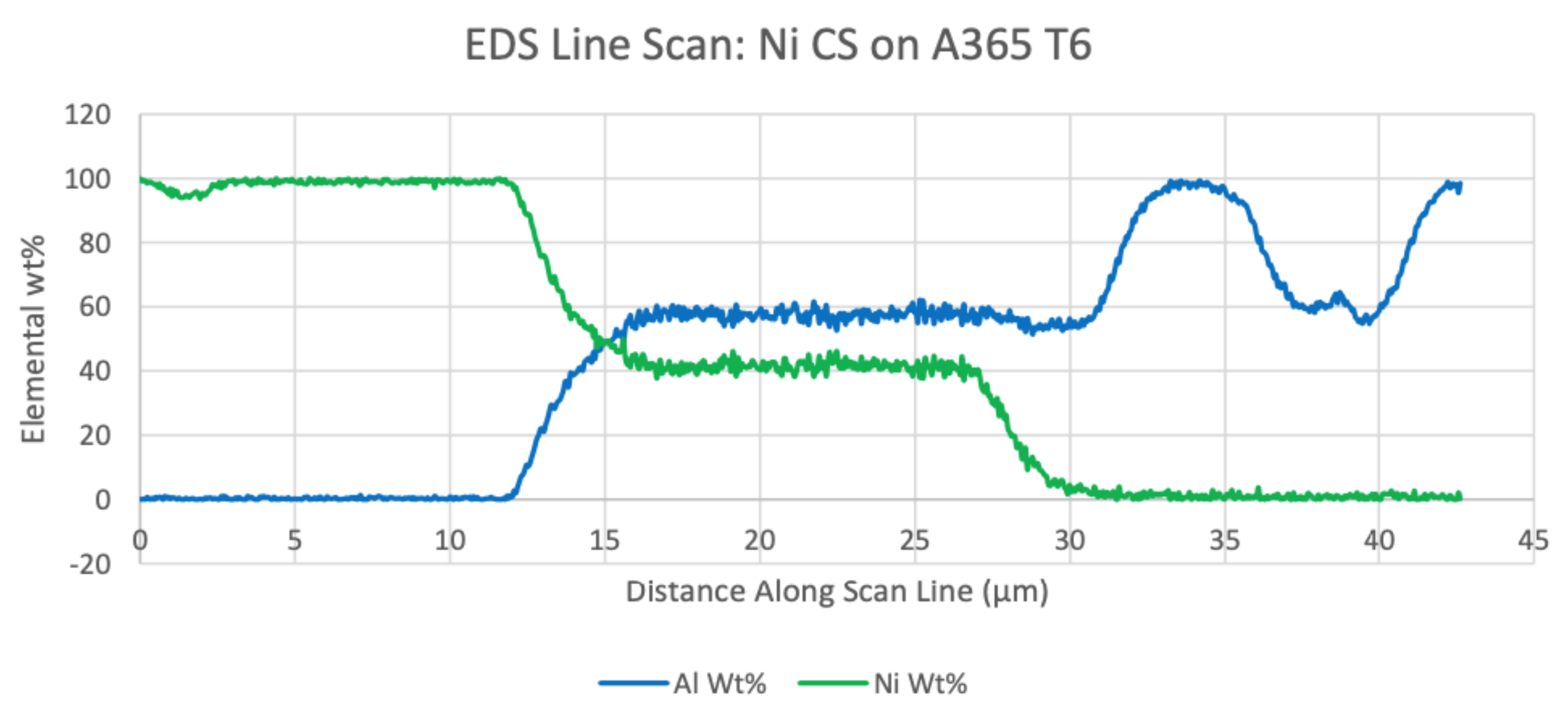
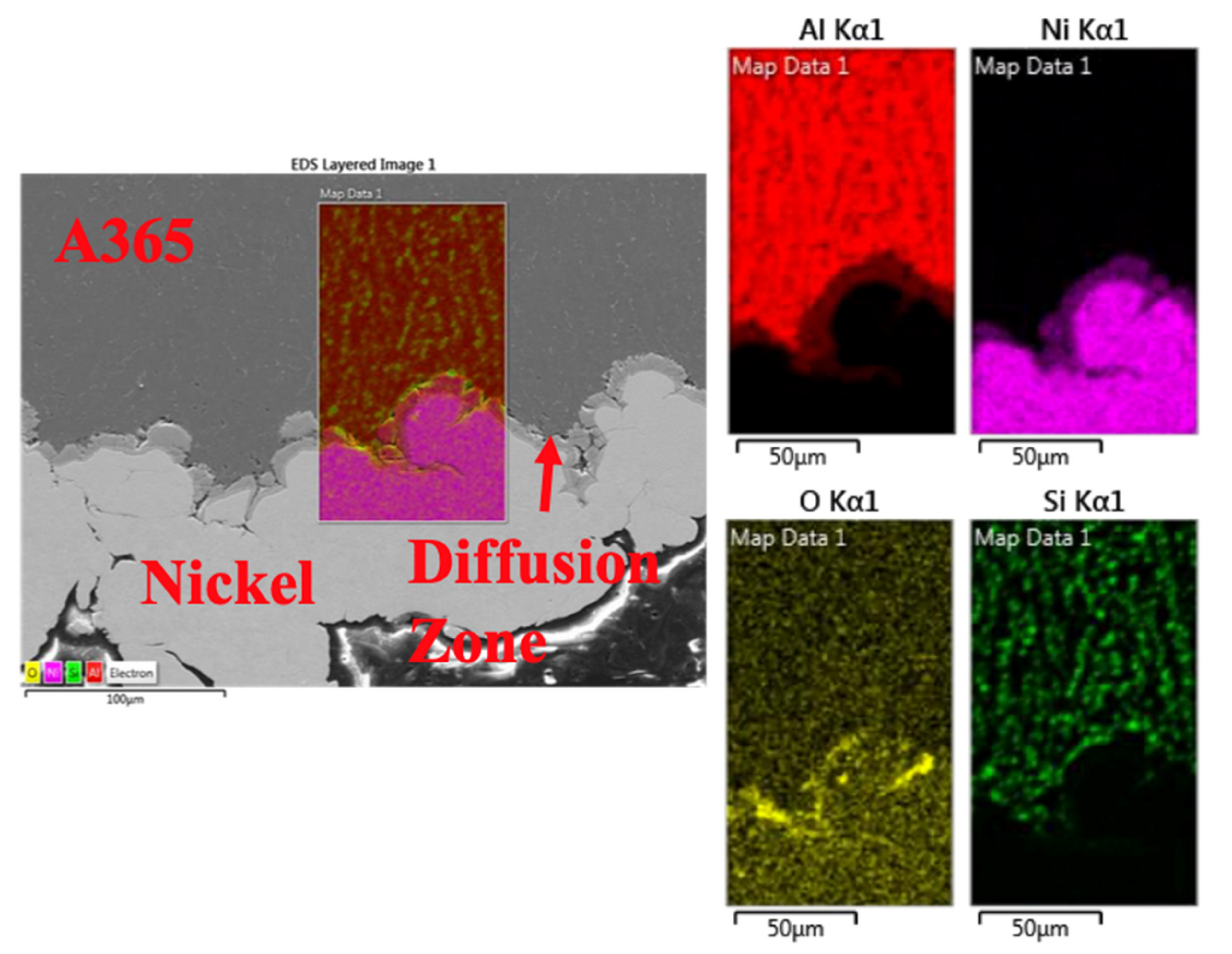
Nickel samples differed from both copper and titanium results in that very little, if any, nickel was held in solid solution. Intermetallics of nickel and aluminum formed, but EDS was not the appropriate method for differentiating the potential phases formed due to each layer’s small thickness and compositional similarity. According to the EDS line scans conducted, potential phases to have formed include Ni
2Al
3, NiAl
3, and NiAl, as exemplified by
Figure 8. If longer solution treatment times were available, all intermetallics expected should form. A feature of note for the nickel diffusion zone was how continuous and relatively smooth the intermetallic layer was compared to copper’s intermetallic layer. Nickel does not appear to have been held in a solid solution with the aluminum matrix. Nevertheless, EDS mapping was also applied, as shown in
Figure 9.
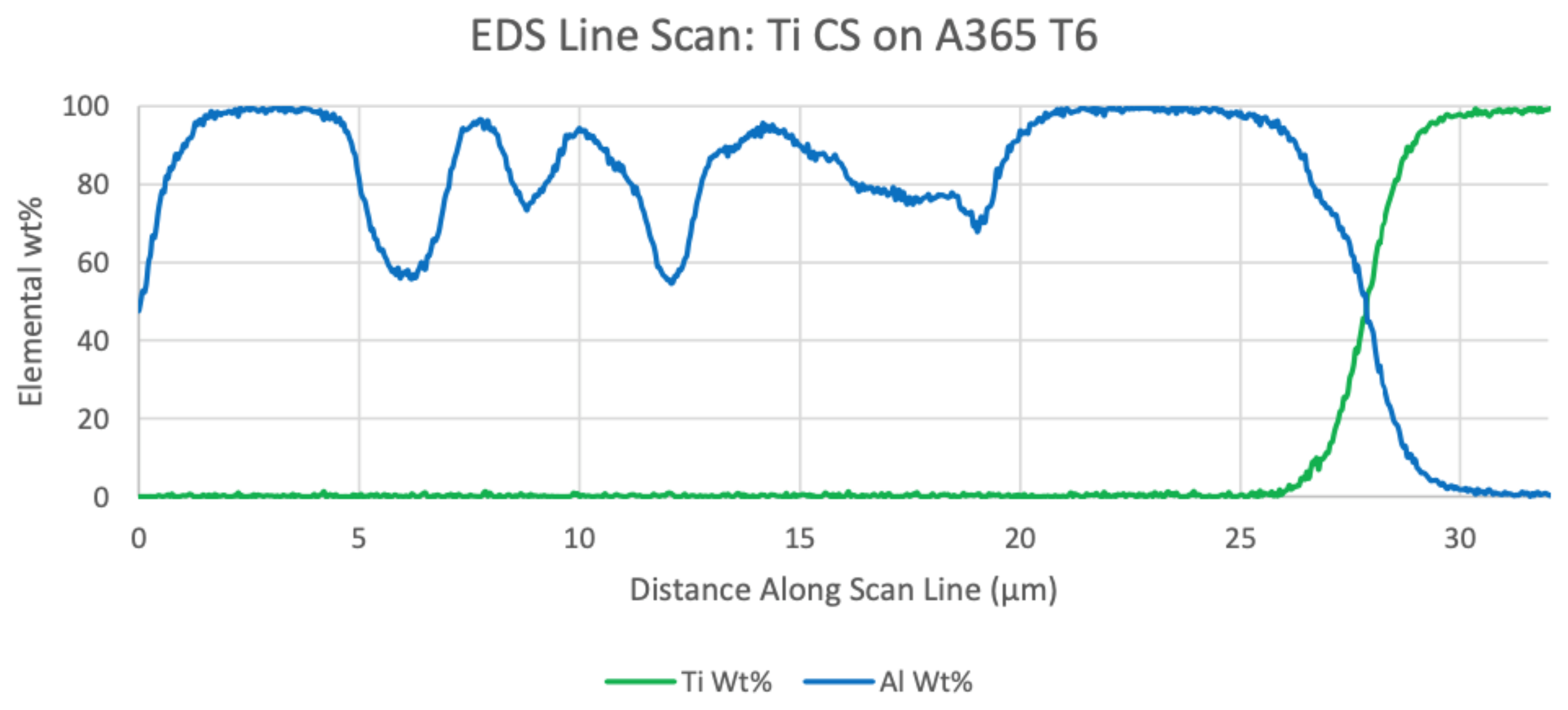
Titanium results from EDS show no significant diffusion into the surface of the aluminum substrate.
Figure 10 shows the line scans of aluminum and titanium against distance along with the scan. In this figure, the titanium coating began on the right-hand side and moved leftwards. An insignificant amount of titanium can be found in the aluminum substrate due to the electron beam’s probe size in EDS analysis. Dips in aluminum content along the scan are due to formations of silicon phases in the bulk of the sample.
A select set of CGDS-based publications were cited in
Section 1 as a means of highlighting how prior work has considered the use of CGDS surface modification for improved mechanical performance and microstructural properties. The subset of works cited at the beginning of the present article does not encapsulate a complete collection of the previously published work of relevance to date. The present section of the current manuscript will briefly build upon how links between reported results and the results presented in this body of work can serve as a pathway for contextualizing the findings.
Liang et al. demonstrated the ability to deposit Zn-Al CGDS coatings onto an interstitial-free Ti-Nb steel substrate system [
47]. Liang et al. studied interfacial compound formation between the Zn-Al coating and substrate when diffusion-driven annealing heat treatments were applied as a postprocessing step at 400 °C. The researchers documented Fe-Zn and Fe-Al-Zn interfacial compounds’ construction upon applying the annealing treatment for 60 min. At the closing of their work, the researchers identified and detailed how enhanced erosion resistance of the automotive steel substrate and enhanced corrosion resistance followed from a hold time of 60 min during annealing [
47]. The current work presents similar findings of foreign phases formed not inherent to the substrate via EDS and micrographs.
From the discussion and contextualization procured by way of referencing [
47] and [
48] above, one may readily appreciate the fact that those mentioned above were formulated as a means of highlighting how prior work has considered the use of CGDS surface modification for application-specific performance-driven scenarios. While additional discussion could have been presented next surrounding the remaining aforementioned topical clusters within the academic literature of relevance presented to date, the current scope, aims, and objectives motivated the authors of the present article to reference the remaining articles not considered herein for curious readers [
49,
50,
51,
52,
53,
54,
55,
56,
57,
58,
59,
60,
61,
62,
63].


