Abstract
Advanced high strength dual-phase steels are one of the most widely sought-after structural materials for automotive applications. These high strength steels, however, are prone to fracture under bending-dominated manufacturing processes. Experimental observations suggest that the bendability of these steels is sensitive to the presence of subsurface non-metallic inclusions and the inclusions exhibit a rather discrete size effect on the bendability of these steels. Following this, we have carried out a series of microstructure-based finite element calculations of ductile fracture in an advanced high strength dual-phase steel under bending. In the calculations, both the dual-phase microstructure and inclusion are discretely modeled. To gain additional insight, we have also analyzed the effect of an inclusion on the bendability of a single-phase material. In line with the experimental observations, strong inclusion size effect on the bendability of the dual-phase steel naturally emerge in the calculations. Furthermore, supervised machine learning is used to quantify the effects of the multivariable input space associated with the dual-phase microstructure and inclusion on the bendability of the steel. The results of the supervised machine learning are then used to identify the contributions of individual features and isolate critical features that control the bendability of dual-phase steels.
1. Introduction
A 10% reduction in the weight of an automobile results in a 6–8% increase in its fuel efficiency [1]. One of the primary approaches to reduce weight is through increased use of materials with relatively high specific strength such as advanced high strength steels [2]. The potential of weight reduction through increased use of advanced high strength steels in automobiles has been estimated to be as high as 25% [3]. Advanced high strength steels derive their exceptional mechanical properties from a well-engineered complex, heterogeneous microstructure. With a few exceptions, most advanced high strength steels comprise two or more phases (a combination of martensite, ferrite, retained austenite or bainite) which help achieve desired properties [2]. Of the various advanced high strength steels, dual-phase steels [4] are one of the most widely sought after materials for automotive applications as they provide adequate compromises on strength and ductility [5]. The microstructure of advanced high strength dual-phase steels primarily consists of hard martensite phase islands dispersed in comparatively softer ferrite phase matrix, together with a small amount of process induced non-metallic inclusions [6].
The influence of the ‘intended’ ferritic-martensitic microstructure on the deformation and fracture response of dual-phase steels has been a topic of numerous experimental [7,8,9,10,11,12,13,14,15,16,17,18] and 2D [10,12,15,18,19,20,21,22,23,24] or 3D [14,17,25,26,27,28] microstructure-based computational studies. These studies have shown that the deformation and fracture characteristics of dual-phase steels, particularly those with high martensite content and tensile strength of order GPa, are quite complex. The macroscopic flow behavior of these dual-phase steels exhibits low initial yield strength due to early yielding in the ferrite phase, followed by steep strain-hardening while the martensite phase is still elastic and finally significant reduction in strain-hardening post yielding in the martensite phase [14,27]. In high strength dual-phase steels decohesion at the ferrite/martensite interface and separation of the adjacent martensite particles result in damage nucleation; while damage evolution depends on the volume fraction, morphology and distribution of martensite islands, and the difference between the mechanical properties of the two phases [7,8,10,11,12,13,15,16,17,18].
In contrast to damage evolution (void growth) in a homogeneous material, void growth along an interface of two elastic-plastic phase (as in dual-phase steels) is much more severe [29] because the coalescence of adjacent voids along the ferrite/martensite interface in the dual-phase steel preferential occurs in the softer ferrite phase and close to the interface [17,24]. This in turn increases the susceptibility of crack nucleation and propagation in high strength dual-phase steels and limits their crashworthiness [30]. The high strength dual-phase steels (with high martensite content and tensile strength of order GPa) are also prone to fracture under bending dominated manufacturing processes [31,32]. At the industrial scale, the bendability of a sheet metal is in general characterized by V-bend test (see Section 2). A series of V-bend tests of a galvannealed dual-phase DP1000 steel sheet revealed significant sample to sample variation in the bendability of the steel. The root cause of the sample to sample variation in the bendability of the steel, through detailed fractographic investigations, was associated with the presence of ‘unintended’ subsurface non-metallic inclusions. Furthermore, it was found that the inclusions in the high strength dual-phase steel exhibit strong size effect on the bendability of the steel sheet.
It is extremely difficult and expensive, if not impossible, to produce inclusion-free steels. Nonetheless, the well-engineered microstructure of advanced high strength dual-phase steels does not contain large amounts of inclusions. Also, the small amount of inclusions in dual-phase steels are in general assumed to have insignificant effect on the mechanical response of the material under simple uniaxial tensile loading condition [33,34]. However, the mechanical response of a dual-phase material in an imposed deformation field that is homogeneous, such as those under uniaxial tension, is different from the response in an imposed deformation field that is heterogeneous, such as those under bending [24]. This is because, in the latter, damage nucleation and evolution involves the interaction of the length-scales induced by both bending and material microstructure. So that, even a subtle difference in the material microstructure is exacerbated under bending. For example, in ref. [24] it was shown that a dual-phase steel which under uniaxial tension exhibits similar mechanical response along the rolling and transverse directions, can exhibit very different mechanical response along the two directions under bending.
The objective of this work is to understand the effects of the length-scales induced by the mode of deformation, i.e., bending, ‘intended’ dual-phase microstructure, and size, shape, location and properties of ‘unintended’ microstructural features, i.e., inclusions, on crack nucleation and early stage crack growth in advanced high strength dual-phase steels. To this end, we have carried out a series of microstructure-based finite element calculations of ductile crack nucleation and early stage crack growth in a dual-phase steel under V-bend loading condition. The microstructure-based finite element modeling in this work builds on our recent work [24] on ductile fracture of dual-phase steels under bending. In the calculations here, not only the ‘intended’ microstructure of an industrially produced dual-phase steel, DP1000, as in ref. [24] but also the ‘unintended’ inclusions are discretely modeled in a thin slice of a bend specimen. To gain additional insight, we have also analyzed the effect of an inclusion on the bendability of a single-phase material with material properties corresponding to the overall mechanical response of the dual-phase steel under consideration.
Our results show that the presence of a subsurface inclusion in the bend specimens leads to subsurface micro-void/crack nucleation under bending that can accelerate the localization of plastic strain in the material. In line with the experimental observations, strong inclusion size effect on the bendability of the dual-phase steels naturally emerge in our calculations. Furthermore, we have also carried out supervised machine learning to quantify the effects of the multivariable input space associated with the ‘intended’ and ‘unintended’ microstructural features on the bendability of the advanced high strength dual-phase steel. The supervised machine learning approach used here utilizes an ensemble learning method for regression analysis. The results of the supervised machine learning are then used to identify the contribution of individual features and isolate critical features that control the bendability of the advanced high strength dual-phase steel. Specifically, the machine learning based analysis shows that unlike a single-phase material, the bendability of a dual-phase steel is not only affected by the features associated with the subsurface inclusion but it is also affected by the underlying dual-phase microstructure.
2. Ninety-Degree V-Bend Tests and Fractographic Analysis
Industrial scale V-bend tests of galvannealed dual-phase DP1000 steel sheets were carried out at ArcelorMittal Global R&D. For the bend tests, mm coupons were cut from steel coils of thickness ≈ mm and were placed in the bend tester where a V-bend punch pushed the coupon into the die at a constant speed. The bent sample was then held under a small load for 5 seconds before the punch was retracted. In all the tests the bend axis was along the rolling direction of the steel sheet and the punch speed was 45 mm/min. Next, the bent coupon was taken out of the fixture and visually examined for cracking on the tension side of the bent specimen. If a bend crack was observed, the specimen was labeled ‘failed’ and the cracked area was marked; otherwise, the specimen was labeled ‘passed’. In either case, the V-bent samples were then manually bent to complete fracture along the bend axis for further examination. The resulting fracture surfaces were examined using scanning electron microscopy (SEM), cathodoluminescence microscopy (CLM) and energy dispersive spectroscopy (EDS) as in ref. [32]. During the fractographic analysis, the distance of the inclusions from the bent surface as well as the size and composition of the inclusions close to bent surface were recorded for both ‘failed’ and ‘passed’ specimens. The microstructure of the undeformed galvannealed dual-phase DP1000 steel sheets were also thoroughly characterized using SEM, CLM and EDS.
The microstructure of the DP1000 dual-phase steel consists of martensite phase islands dispersed in the ferrite phase matrix, together with a small amount of non-metallic inclusions as shown in Figure 1a,b. A cross-section of the surface crack nucleated in a V-bent coupon is also shown in Figure 1c. The influence of the distance of the inclusions from the bent surface (Location) and the size of the inclusions on the nucleation of a surface crack in the bent coupons is shown in Figure 1d. As can be seen in the figure, the inclusions in the high strength dual-phase steel exhibit strong size effect on the bendability (or crack nucleation propensity) of the sheet metal.
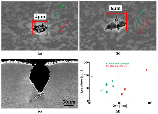
Figure 1.
SEM images of an advanced high strength dual-phase, DP1000, steel specimens showing (a,b) the ‘intended’ ferritic (F)-martensitic (M) microstructure and ‘unintended’ subsurface inclusions in the undeformed material and (c) cross-section of a deep surface crack formed during 90 V-bending. (d) Experimental results showing the effects of the location (distance from the tension side free surface) and size of subsurface inclusions on the bendability of DP1000 steel sheets.
3. Problem Formulation and Numerical Method
As in ref. [24], microstructure-based finite element modeling of deformation and fracture of a dual-phase steel sheet subjected to V-bend loading condition are carried out for a thin slice of material with dimension along z-axis, i.e., mm, and other dimensions and details shown in Figure 2. Note that the dimensions of the specimen modeled, except the thickness (dimension along y-axis), is smaller than the dimension of the specimens employed in the industrial scale V-bend tests, Section 2. This is to decrease the computational time of the finite element calculations. The finite element calculations are carried out using our in-house data parallel finite element code [24,35,36,37], which is based on the dynamic principle of virtual work using a finite deformation Lagrangian convected coordinate formulation. More complete description of the finite element method is given in the references cited. For the finite element mesh, a single element through the width, W, of the specimen is used and overall plane strain conditions are imposed on and surfaces. A very fine uniform in-plane ( plane) mesh is used in a mm region (marked as in Figure 2) near the free surface of the bend specimen with in-plane element dimension μm. The element dimension in the fine mesh region, μm, serves as a normalization length-scale. The finite element mesh of the entire specimen consists of 22,920 twenty-node brick elements. A mesh convergence study in ref. [24] showed that for the mesh size considered in the fine mesh region, the effect of the mesh size is not dominant on the predictions of these microstructure-based finite element calculations.
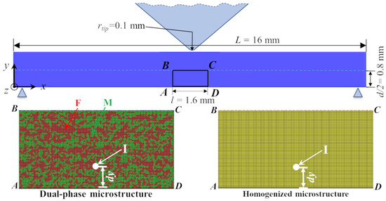
Figure 2.
(top) A schematic of the bend specimen together with imposed constraint and loading conditions. (bottom left) A zoomed view of the finite element mesh near the free surface of the bend specimen of a dual-phase steel showing the discretely modeled ferrite (F) and martensite (M) phases, and an inclusion (I). (bottom right) A zoomed view of the finite element mesh near the free surface of the bend specimen of a single-phase material with an inclusion (I).
The imposed boundary and loading conditions follows the configuration shown schematically in Figure 2. As shown in the figure, in the reference configuration, the y-displacement of the specimen is constrained at locations, , mm and , mm, and the tip of the punch is in contact with the specimen at mm, mm. A time varying velocity, , in the negative y direction is imposed on the tip of the punch that follows the relation:
where t is the analysis time, is the rise time and is the final velocity of the punch. In the calculations, s and mm/s is used. A rather high value of the final velocity, , is chosen to reduce the computational time of the finite element calculations, while the time varying velocity, , is applied to minimize the wave effect in the dynamic calculations, since the focus here is on the quasi-static response. As the tip of the punch moves in the negative y direction, additional nodes on the specimen surface comes in contact with the V-bend punch and these nodes are also assigned the value of which is equal to the velocity of the tip at the time of contact and , which corresponds to perfect sticking of the material to the punch.
3.1. Microstructure Modeling
As shown in Figure 2, we discretely model the material microstructure in a small but large enough region to capture the nucleation and coalescence of micro-cracks near the free surface of the specimen. To this end, 2D SEM images of the microstructure of the material are digitized via Marker-Controlled Watershed Segmentation method [38]. The average size of the ferrite and martensite phases in the as-produced steel are 2.09 μm and 1.76 μm. Next, the SEM image is magnified by 20X to ‘artificially’ increase the feature sizes to allow us to choose a reasonable mesh size to resolve the details of the dual-phase microstructure. The 20X magnification increases an actual length of 1 m to 20 m or in terms of the element dimension, e, it is simply , while keeping the overall volume fraction of the phases fixed. The average size of the ferrite and martensite phases modeled in terms of the element dimension are ( =) and ( =) , respectively. Finally, an inclusion of radius, , is introduced in the digitized and magnified microstructure in the center along the length of the bend coupon (marked as ‘I’ in Figure 2) at a distance from the free surface on the tension side. Note that we only model a single inclusion, however, given the extremely small amount of overall inclusions in the well-engineered microstructure of the advanced high strength dual-phase steel, any inclusion-inclusion interaction can be neglected. Also note that this single inclusion is always assumed to be present in the center along the length of the bend coupon which constitutes a worst-case scenario. The dual-phase microstructure together with the inclusion are then superimposed on the finite element mesh in the region marked as in Figure 2, and material properties corresponding to the respective microstructural features are assigned based on material (Gaussian) integration points rather than the finite elements. This allows us to smoothly resolve the interphase boundaries. The region outside in the bend specimen are assigned the material properties corresponding to the overall mechanical response of the dual-phase steel under consideration. To gain additional insight, we have also analyzed the effect of an inclusion on the bendability of a single-phase material, Figure 2, with constitutive parameters corresponding to the overall ‘homogenized’ dual-phase steel under consideration.
3.2. Constitutive Framework
The constitutive framework for a progressively cavitating ductile solid is used in the form of a modified Gurson constitutive relation [39,40,41], with the flow potential
where , are parameters introduced in refs. [42,43]. In Equation (2), is the matrix flow strength, is the Mises effective stress, is the hydrostatic stress and is the effective void volume fraction given by
where, f is the void volume fraction, is the critical void volume fraction to void coalescence and is the void volume fraction at failure.
The rate of deformation tensor, , is taken as the sum of an elastic part, , and a viscoplastic part, . The elastic part is , where is the Jaumann rate of Cauchy stress and is the tensor of isotropic elastic moduli as characterized by the Young’s modulus, E, and Poisson’s ratio, . The viscoplastic part, , is given as [44]
with the matrix plastic strain rate, , having the form
where , is the reference strain rate, m is the strain rate sensitivity exponent, is the reference flow strength, is a reference strain and N is the strain hardening exponent.
The evolution of the void volume fraction, f, is governed by
where the first term on the right hand side of Equation (6) accounts for void growth and the second term accounts for void nucleation. The value of f in the undeformed configuration, i.e., value of f at time, , represents the initial void volume fraction, . The void nucleation in the ferrite and martensite phases is assumed to follow strain-controlled nucleation given as [41]
whereas, the void nucleation due to non-metallic inclusions is considered to follow stress-controlled nucleation given as [41]
if , where the maximum is taken over the previous deformation history, and , else . In Equations (7) and (8), , , , , and are the constitutive parameters.
3.3. Constitutive Parameter Identification
The constitutive framework described in Section 3.2 contains several constitutive (material) parameters that need to be determined. The values of the constitutive parameters associated with the elastic-viscoplastic response of the fully dense ( throughout the deformation) ‘homogenized’ dual-phase microstructure and that of the individual constituent phases, ferrite and martensite, of the DP1000 steel under consideration were determined in ref. [24] by employing an iterative optimization scheme to minimize the mean squared error between the stress-strain response (prior to the onset of necking) obtained from uniaxial tension tests and microstructure-based finite element calculations of 3D representative volume elements subjected to uniaxial tension. The values of all the parameters obtained in ref. [24] are given in Table 1. Since the values of the parameters in ref. [24] were obtained for uniaxial tension so the question arises to what extent these parameters can approximate the flexural stress-strain response of the material under 90 V-bending. A comparison of the early stage macroscopic flexural stress ()-plastic strain () response of the DP1000 steel sheets obtained from 90 V-bend tests and microstructure-based finite element calculation using the values of the parameters given in Table 1 are shown in Figure 3. The values of the macroscopic flexural stress and total flexural strain () are estimated as,
where, is the reaction force on the punch and is the deflection of the tip of the punch along the loading direction. For the microstructure-based finite element calculation in Figure 3 only the dual-phase microstructure of the steel (without any inclusion) is considered, and the calculations are carried out with throughout the deformation history, i.e., the initiation and evolution of ductile damage is suppressed. Despite the various simplifying assumptions in the numerical method such as, considering only a 2D slice of the microstructure, difference in the specimen geometry and loading rate as well as the fact that the parameters were obtained from a tension test, a rather good agreement between the calculated and the experimentally obtained early stage deformation response of the DP1000 steel sheet under 90 V-bending in Figure 3 is noted.

Table 1.
The values of the constitutive parameters for the overall (homogenized) dual-phase (DP) steel [24], the individual constituent phases (ferrite and martensite) [24] and the non-metallic inclusion.
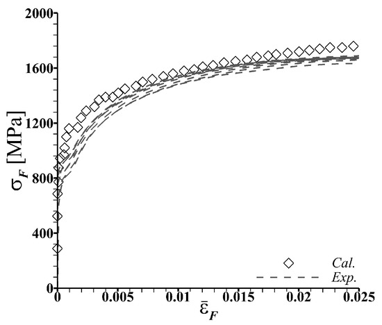
Figure 3.
Comparison of the early stage macroscopic flexural stress ()-plastic strain () response of the DP1000 steel sheets obtained from 90 V-bend tests () and microstructure-based finite element calculation (). In the microstructure-based finite element calculation the dual-phase microstructure of the steel without any inclusion is discretely modeled in the bend specimen, see Figure 2.
Next, the values of the constitutive parameters associated with the elastic-viscoplastic response of the inclusion in Table 1 are chosen to represent generic non-metallic inclusions such as, spinels, calcium aluminates, silicates, titanium nitride and alumina, that undergo linear elastic deformation up until the onset of damage nucleation, note for the inclusion , where is the damage nucleation strength of the inclusion defined in Equation (8). As modeled, any inelastic deformation that occurs in the inclusions, occurs post damage nucleation and are modeled to allow graceful fracture of the inclusion for numerical convenience.
Apart from the constitutive parameters needed to model the mechanical response of the fully dense material that are given in Table 1, the constitutive framework detailed in Section 3.2 also contains parameters associated with the modified Gurson model. These parameters for the ferrite and martensite phases, and for the ‘homogenized’ dual-phase steel are, initial void volume fraction, , critical void volume fraction to void coalescence, , void volume fraction at failure, , and the three parameters, , , associated with the void nucleation criteria in Equation (7). Following the work of ref. [24], we take, for the ferrite phase, for the martensite phase, and for the ‘homogenized’ dual-phase, while , , , , and are taken to be the same for all three. For the non-metallic inclusion, , , , and the two parameters associated with Equation (8), and are used in the calculations. Parametric studies are carried out to explore the effect of , i.e., the strength of the inclusion on the bendability of the steel sheets.
4. Numerical Results
Our objective is to understand the effects of the length-scales induced by V-bending, ‘intended’ dual-phase microstructure, and ‘unintended’ inclusions, on crack nucleation and early stage crack growth in advanced high strength dual-phase steels. For the purpose of comparison and to gain additional insight, we have also analyzed the effect of an inclusion on the bendability of a single-phase material with constitutive parameters corresponding to the overall ‘homogenized’ dual-phase steel under consideration. Herein, we first present the key results of the finite element calculations of ductile fracture under V-bending in a single-phase material with an inclusion which is followed by the results of the calculations for the dual-phase steel, i.e., discretely modeled microstructure and inclusion.
4.1. Effect of an Inclusion on the Bendability of a Single-Phase Material
The near surface distribution of equivalent plastic strain, , on the tension side (in the region labeled as in Figure 2) of a V-bend specimen of a single-phase material with an inclusion at four macroscopic flexural strain () levels together with the macroscopic flexural stress ()-strain response are shown in Figure 4. For the specimen in Figure 4, inclusion size, (e is a normalization length-scale introduced in Section 3), strength, ( is defined in Equation (8) and is the initial flow strength of the ‘homogenized’ dual-phase or simply single-phase material given in Table 1) and is located at a distance, ( is the distance from the free surface and d is the thickness of the specimen, Figure 2).
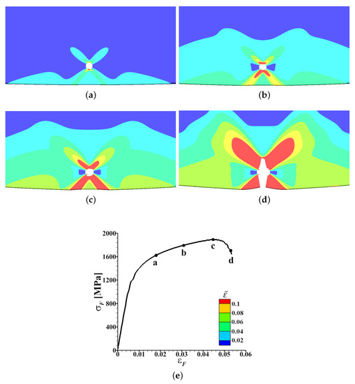
Figure 4.
(a–d) The distribution of equivalent plastic strain, , in the near surface region on the tension side of a deformed V-bend specimen of a single-phase material with an inclusion of size, , strength, MPa () and location, , at four macroscopic flexural strain, , levels marked as, a-d, on the macroscopic flexural stress ()- curve in (e).
As shown in Figure 4a–c, in a single-phase material, subsurface void nucleation (‘white’ region in the figures) due to the presence of a subsurface inclusion results in the localization of in bands emanating from the subsurface void that are oriented at ≈ with respect to the loading axis. As also shown in Figure 4a–c, the intensity of the localization of increases with progressive bending. Next, with continued bending, the ligament between the surface and the subsurface micro-crack parallel to the loading direction undergoes slight localized thinning that results in an increase in the value of the stress triaxiality in the thinned ligament. Subsequently, nucleation and propagation of a crack connecting the surface and the subsurface void, Figure 4d, results in the final fracture, i.e., loss of the load bearing capacity of the specimen which is marked by a drop in the value of , Figure 4e. The ductile fracture mechanism of the single-phase material with an inclusion under bending shown in Figure 4 is qualitatively the same for the range of inclusion size, , and location, , considered in this work.
The effects of the inclusion size, , location, , and strength, , on the bendability of a single-phase material with a subsurface inclusion are shown in Figure 5. The bendability of a specimen is characterized by the value of the macroscopic flexural strain to failure, , which is the value of that corresponds to the drop in the value of . As shown in Figure 5a, for an inclusion of strength, MPa, which is less than the initial flow strength, , of the material, the value of increases roughly linearly with increasing distance, , of the inclusion from the surface, for all three values of considered in this work. While for a fixed value of , the value of decreases with increasing value of . The effects of the inclusion size and location on the bendability of a single-phase material shown in Figure 5a is unaffected by an increase in the value of the inclusion strength from MPa to MPa , as shown in Figure 5b. Although, not presented here, we have also analyzed the effect of an inclusion of strength, . Our results show that a significant increase in the strength of the inclusion above the initial flow strength of the material improves the bendability of the material for a fixed inclusion size and location.
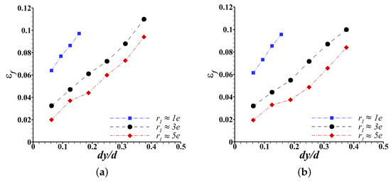
Figure 5.
Effect of the size, , and location, , of an inclusion of strength (a) MPa () and (b) MPa () on the flexural strain to failure, , (i.e. bendability) of a single-phase material.
4.2. Effect of an Inclusion on the Bendability of a Dual-Phase Material
The near surface distribution of on the tension side of a V-bend specimen of the dual-phase steel with an inclusion of size, , strength, ( is the initial flow strength of the ferrite phase) and location, , at four values of together with the - response are shown in Figure 6. As shown in Figure 6a–c, the presence of an inclusion results in a subsurface void nucleation (‘white’ region in the figures) and with progressive deformation localizes in a band emanating from the free surface that is oriented at an angle close to (but not at) with respect to the loading axis. Also, with continued bending, the intensity of the localization of in the band increases, the subsurface void starts to grow and a micro-crack nucleate at the free surface, Figure 6b. Subsequently, the subsurface micro-crack connects with the surface micro-crack along the localization band of , Figure 6c,d, resulting in final fracture at a distance from the center of the specimen. The final fracture of the specimen leads to a drop in the value of , Figure 6e.
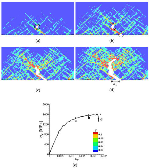
Figure 6.
(a–d) The distribution of equivalent plastic strain, , in the near surface region on the tension side of a deformed V-bend specimen with ‘discrete’ dual-phase microstructure and an inclusion of size, (), strength, MPa () and location, , at four macroscopic flexural strain, , levels marked as, a-d, on the macroscopic flexural stress ()- curve in (e).
Next, we consider a specimen with everything being the same as the specimen in Figure 6 but with an inclusion of size, . The near surface distribution of on the tension side of this specimen at four values of together with the - response are shown in Figure 7. As shown in Figure 7a, here as well, the subsurface inclusion results in subsurface void nucleation. However, the nucleated void does not significantly affect the localization of and the localization of predominantly depends on the interlacing of the length-scales induced by bending and the discreteness of the underlying dual-phase microstructure. With progressive deformation, the intensity of the localization of in the band increases and a surface micro-crack nucleates, while the inclusion induced subsurface void does not grow significantly, Figure 7b,c. Subsequently, the surface micro-crack grows inwards while completely ignoring the inclusion induced subsurface void, Figure 7d. The growth of the surface micro-crack results in final fracture, i.e., drop in the value of , Figure 7e.
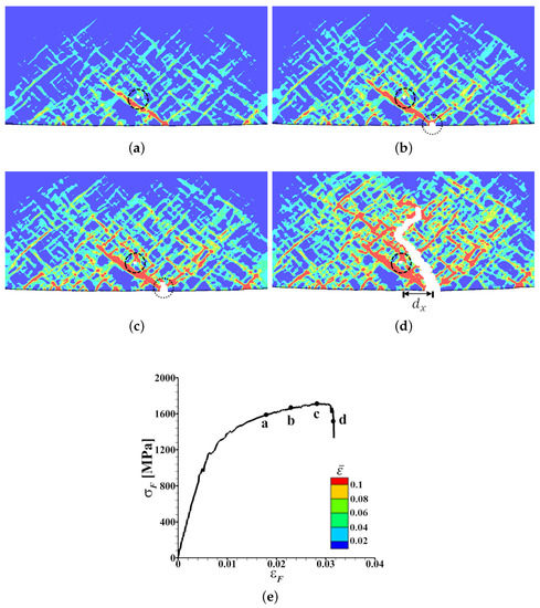
Figure 7.
(a–d) The distribution of equivalent plastic strain, , in the near surface region on the tension side of a deformed V-bend specimen with ‘discrete’ dual-phase microstructure and an inclusion of size, (), strength, MPa () and location, , at four macroscopic flexural strain, , levels marked as, a-d, on the macroscopic flexural stress ()- curve in (e).
The effects of the inclusion size, , location, , and strength, , on the bendability of the dual-phase steel with a subsurface inclusion are shown in Figure 8. As in Figure 5, the bendability of the dual-phase specimen is also characterized by the value of at failure, . The values of in Figure 8 are normalized by the values of the macroscopic flexural strain to failure of the underlying inclusion free dual-phase steel microstructure, . For a fixed value of , and of the inclusion, calculations are carried out for five underlying dual-phase steel microstructures taken from different locations of the dual-phase steel under consideration. The error bars in Figure 8 are the standard error for five realizations of the underlying dual-phase steel microstructure.
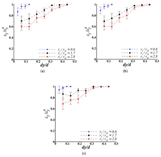
Figure 8.
Effect of the size, , and location, , of an inclusion of strength (a) MPa ( and ), (b) MPa ( and ) and (c) MPa ( and ) on the flexural strain to failure, , (i.e., bendability) of the dual-phase steel.
As shown in Figure 8a, for an inclusion of strength, MPa, which is less than the initial flow strength of both the ferrite and martensite phases, and a fixed size, the value of first increases with increasing value of and then tends to saturate. The saturation in the value of corresponds to , implying that the detrimental effect of the inclusion on the bendability of the dual-phase steel vanishes. The value of for which strongly depends on the inclusion size relative to the size of the martensite phase. For example, for inclusions of size, and , the values of for which are and , respectively. While for an inclusion of size, , the value of for which is . The effects of the inclusion size and location on the bendability of a dual-phase steel shown in Figure 8a is not significantly affected by an increase in the value of the inclusion strength from MPa to MPa, as shown in Figure 8b. The value of inclusion strength, MPa, is greater than the initial flow strength of the ferrite phase but is less than the initial flow strength of the martensite phase. However, a further increase in the value of the inclusion strength such that the inclusion is stronger than the martensite phase significantly improves the bendability of the dual-phase steel sheet for a fixed inclusion size and location, Figure 8c. A notable observation from Figure 8c is that the detrimental effect of an inclusion which is smaller but stronger than the martensite phase on the bendability of a dual-phase steel is negligible. Finally, the error bars on the values of for a fixed inclusion size, location and strength in Figure 8 highlight that the detrimental effect of an inclusion on the bendability of a dual-phase material is also sensitive to the variations in the underlying dual-phase microstructure.
We also carried out limited analyses of the effect of the shape of an inclusion on the bendability of the dual-phase steel. To this end, we modeled an elliptical inclusion of size, along the length and along the thickness (loading direction) of the specimen. The cross-sectional area, , of all the elliptical inclusions are taken to be (giving, ) while their aspect ratio, are varied. The effect of the aspect ratio of an inclusion center located at on the normalized macroscopic flexural strain to failure, , for three inclusion strength levels together with schematics of elliptical inclusions modeled are shown in Figure 9. As shown in the figure, for all three inclusion strengths, the value of macroscopic flexural strain to failure, , increases with increasing aspect ratio of the elliptical inclusion for aspect ratios less than 4. While the detrimental effect of the aspect ratio of the elliptical inclusion on the bendability of the dual-phase steel vanishes for aspect ratios greater than 4. Similar to the results presented in Figure 8, here as well, increasing the inclusion strength such that the inclusion is stronger than the martensite phase (, i.e., ) improves the bendability of the dual-phase steel especially when the aspect ratio of the elliptical inclusion is less than 4.
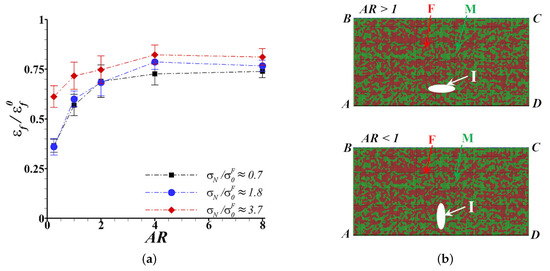
Figure 9.
(a) Effect of the aspect ratio () of an elliptical inclusion on the flexural strain to failure, , (i.e., bendability) of the dual-phase steel. The cross-section area of the inclusion, (giving ), and the location of the inclusion center, , is fixed in all the calculations. (b) Schematic of elliptical inclusions with aspect ratio (AR) greater than (top) and less than (bottom) one.
5. Supervised Machine Learning Approach and Predictions
We first present the supervised machine learning approach and predictions of the effect of an inclusion on the bendability of the simple single-phase material in Section 5.1. The approach and results of the supervised machine learning on the effect of an inclusion on the bendability of more complex dual-phase material is presented in Section 5.2.
5.1. Effect of an Inclusion on the Bendability of a Single-Phase Material
For the simple single-phase material with a subsurface inclusion, we consider inclusion size, , location, , and strength, , as the input space while the macroscopic flexural strain to failure, , is the target or the output space. The goal is to quantify the effect of the individual input variables on the response. To this end, we choose the simplest supervised machine learning approach, linear regression analysis. The accuracy of the regression analysis is evaluated by the widely used performance measure, coefficient of determination, [45]. The is the proportion of the variance in the dependent variable that is predictable from the independent variable and is a statistical measure of how well the regression predictions approximate the actual data. The value, , indicates that the regression model explains all the variability in the response data around its mean.
The results of the linear regression analysis are shown in Figure 10. The correlation matrix of the three input variables, , and in Figure 10a clearly shows that these three input variables are not highly correlated. A comparison of the predictions of the linear regression analysis and the results of the microstructure-based finite element calculations are shown in Figure 10b. As shown in the figure, the two predictions are in very good agreement and the value of . The final calibrated linear regression model follows:
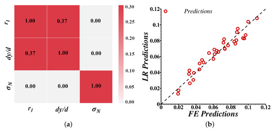
Figure 10.
(a) Correlation matrix of variables in analyzing the effect of an inclusion on the bendability of the single-phase material. (b) Comparison of the macroscopic flexural strain to failure, , predicted using linear regression () analysis and microstructure-based finite element () calculations.
The calibrated linear regression model in Equation (10) shows that the inclusion size and location are the two important features that greatly affect the bendability of the simple single-phase material with a subsurface inclusion. While the inclusion strength (as long as the strength of the inclusion is less than or comparable to the initial flow strength of the material) has a small effect on the bendability of the single-phase material.
5.2. Effect of an Inclusion on the Bendability of a Dual-Phase Material
The results of the microstructure-based finite element calculations in Section 4.2 suggest that there are several features associated with an inclusion that affect the bendability of the dual-phase steel. While the results of the microstructure-based finite element calculations of the bendability of the dual-phase steel without any inclusion in ref. [24] suggest that there are several additional features associated with the underlying dual-phase microstructure that also affect the bendability of the material. In particular, in ref. [24], it was found that the intrinsic bendability of the dual-phase steel (i.e., without inclusion) depends on the volume fraction of the martensite in a small region in the center of the specimen on the tension side, the volume fraction of the martensite in a small region at the fracture initiation site, and the distance between the center of the bend specimen and the fracture initiation site. Apart from these the effect of an inclusion, especially that of smaller sizes, on the bendability of the dual-phase steel may also depend on its neighboring phase, i.e., does the inclusion entirely lie in the ferrite phase, martensite phase or it extends over both the phases. All the possible features associated with both the ‘unintended’ and ‘intended’ microstructural features that may affect the bendability of a dual-phase steel are given in Table 2.
Table 2.
All the possible features identified from microstructure-based finite element calculations that may affect the bendability of the dual-phase steel with (in this work) and without (in ref. [24]) an inclusion.
We first followed the simple supervised machine learning approach, linear regression analysis, as in Section 5.1 to quantify the effects of all the input variables in Table 2 on the response, i.e., normalized macroscopic flexural strain to failure, , and identify any redundancy in the input space. To this end, the results of of microstructural-based finite element calculations carried out in this work were randomly selected to train the linear regression model. The trained linear regression model was then tested on remaining of the data set. The accuracy of the regression analysis was evaluated by two performance measures [45], coefficient of determination, , as in Section 5.1 and mean squared error, . is the average of the squares of the errors and indicates that the estimator predicts observations with perfect accuracy. However, not only the input space for the dual-phase steel is significantly greater than the single-phase material, the effect of inclusion on the bendability of the dual-phase steel is also extremely non-linear. Thus, due to these complexities, the trained linear regression model failed to reasonably predict the bendability of the test cases. The values of and for the test cases were found to be and , respectively.
Next, we chose a more sophisticated supervised machine learning approach, random forest regression analysis. The random forest supervised machine learning approach has been extensively applied for predictive analytics and is a type of additive model that makes predictions by combining decisions from a sequence of base models. In addition, the feature importance can be obtained by permuting the values of the input variables and measuring their impact on prediction accuracy. For regression, the variance of random forest model is the measure of impurity. Thus, when training a tree, it is possible to compute how much each feature decreases the impurity. The more a feature decreases the impurity, the more important is the feature. In random forests, the impact on impurity of each feature can be averaged across trees to determine the final importance of the variable. To avoid over-fitting and minimize selection bias, 10-fold cross-validation scheme was chosen for regression analysis. While grid-search was used to find the optimal hyper-parameters of the random forest model that results in the most accurate predictions.
At first we build a random forest model with all 10 features listed in Table 2 and their importance is shown in Figure 11a. As shown in the figure, not all features have the same impact on the bendability of the dual-phase steel. The two most important features that greatly affect the bendability of the dual-phase steel are the inclusion size along the thickness of the sheet, , and the location of the inclusion, . These two features are also the most important features that affect the bendability of the single-phase material. However, there are features associated with the ‘intended’ dual-microstructure such as projected distance between the center of the specimen and the location of the crack initiation site, , and the volume fraction of the martensite in a small box in the center of the specimen, , that have small but significant impact on the bendability of the dual-phase steel. Thus, we carried out feature reduction by building random forest models using a sub-set of the features in Table 2 and rigorously testing their performance. The performance of the random forest model based on all the features as well as four example sub-sets of features are given in Table 3. As shown in Table 3, the performance of a random forest model built using the seven most important features, set 2, is the best. Among the seven features, five of them are associated with the inclusion and two are associated with the underlying dual-phase microstructure. Note, that the performance of a random forest model built using only the features associated with the inclusion, set 5, is the worst. A comparison of the bendability, normalized macroscopic flexural strain to failure, , obtained from the random forest model built using the feature set 2 in Table 3 and microstructure-based finite element calculations of V-bending of the dual-phase steel is shown in Figure 11b. A good correlation between the predictions of the random forest machine learning model and the microstructure-based finite element calculations in Figure 11b is noted.
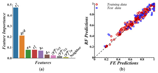
Figure 11.
(a) Feature importance obtained from the random forest regression analysis of the effect of an inclusion on the bendability of the dual-phase steel. (b) A comparison of the bendability, normalized macroscopic flexural strain to failure, , obtained from random forest regression analysis using feature set 2 in Table 3 and microstructure-based finite element calculations of V-bending of the dual-phase steel.
Table 3.
Feature reduction using random forest regression analysis of the effect of an inclusion on the bendability of the dual-phase steel. The description of all the features are given in Table 2. The value of is the coefficient of determination of the fit, (CV) is the mean squared error of the cross-validation predictions, and (Test) is the mean squared error of the test data.
With the trained random forest machine learning model (with feature set 2 in Table 3 as input space and corresponding values of as output space) at hand, we now analyze the partial dependence of few key features on the bendability () of the dual-phase steel. The partial dependence plots allow us to visualize the marginal effects of select features at a time on the predicted outcome [46]. The partial dependence function is given as:
with being the features for which the partial dependence function is sought and are the other features of the input space used in the machine learning model, . The partial dependence works by marginalizing the output of the machine learning model over the distribution of the features in the set , so that the function highlights the correlation between the features of interest, i.e., the feature set and the predictions. The partial function, , is estimated by calculating averages in the training data (also referred to as Monte Carlo Method):
where are the values of the features from the data set and n is the number of instances in the data set.
The partial dependence plots visualizing the effects of a combination of two features associated with the inclusion on the bendability (values of ) of the dual-phase steel are shown in Figure 12. These plots clearly highlight the extremely non-linear and oftentimes discrete effect of individual features associated with the inclusion on the bendability of the dual-phase steel. The partial dependence plot in Figure 12a shows that the detrimental effect of a smaller inclusion decreases rapidly as the distance of the inclusion from the free surface increases. However, the detrimental effect of a relatively larger inclusion is rather insensitive to its location. The partial dependence plot in Figure 12b shows that the detrimental effect of an inclusion that is close to the free surface decreases with increasing inclusion strength for inclusion strength sufficiently greater than the strength of the ferrite phase. While the effect of an inclusion that is located far away from the free surface is rather insensitive to the inclusion strength. Similarly, the partial dependence plot in Figure 12c shows that the detrimental effect of a large inclusion decreases with increasing inclusion strength but that of a small inclusion is relatively insensitive to the inclusion strength.
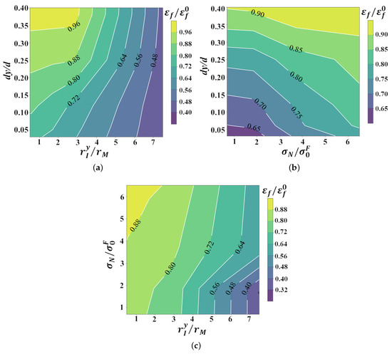
Figure 12.
Partial dependence plots showing the effects of (a) normalized location, , and size, , (b) normalized location, , and strength, , and (c) normalized strength, , and size, , of the inclusion on the bendability, i.e., the normalized macroscopic flexural strain to failure, , of the dual-phase steel.
6. Discussion
An imposed three-point bending like deformation, such as V-bending on the specimen of a single-phase isotropic elastic-plastic material induces a single length-scale. This results in a smooth gradient in the distribution of the equivalent plastic strain, , with the value of being greater at the free surface close to the center of the specimen along the length direction [24]. Even in this simple problem, introducing a single subsurface inclusion in the material induces another (microstructure-based) length-scale. The interaction of the length-scales induced by the mode of deformation and the microstructure greatly affects the deformation pattern as well as damage nucleation and evolution in the material. Our results show that the subsurface void nucleation due to the presence of the inclusion in a single-phase material under V-bending results in plastic strain localization in bands. These bands emanate from the subsurface void and are oriented at ≈ with respect to the loading axis. Next, with continued bending the ligament between the surface and the subsurface void parallel to the loading axis undergoes ductile fracture post-localized thinning.
Unlike a single-phase material, in a specimen of a dual-phase steel, V-bending induces one length-scale, while the discreteness of the underlying dual-phase microstructure induces another length-scale(s). The interlacing of these length-scales results in an overall gradient in the distribution of with the value of being greater at the surface and within this overall gradient the value of is greater in the soft ferrite phase [24]. Also, due to the local constrained imposed by the distribution of the hard martensite phase, the value of the stress triaxiality is greater in the soft ferrite phase close to ferrite-martensite interface [17,24]. Next, the presence of a subsurface inclusion in the dual-phase microstructure may induce yet another length-scale(s) and the interlacing of all these length-scales greatly affects the distribution of as well as the crack nucleation and growth in the specimen. Specifically, in a bend specimen of a dual-phase steel with a subsurface inclusion of size sufficiently greater than the martensite phase and/or located rather close to the free-surface, the distribution of localizes in an inclined band emanating from the free-surface towards the subsurface void nucleated at the inclusion. Finally, with continued bending ductile fracture occurs along the localization band. However, in a bend specimen of a dual-phase steel with a subsurface inclusion of size comparable to (or less than) the martensite phase and/or located sufficiently away from the free-surface, the localization band of emanating from the free-surface ignores the subsurface void nucleated at the inclusion. Under these circumstances, the detrimental effect of the presence of an inclusion is negligible and the bendability of the specimen is largely dictated by the underlying dual-phase microstructure of the material.
The results of our parametric studies show that for a fixed inclusion size and location, and other material properties, the effect of the strength of the inclusion on the bendability of both single-phase and dual-phase materials is somewhat discrete. For instance, the strength of the inclusion does not significantly affect the bendability of a single-phase material as long as the strength is less than or comparable to the flow strength of the material. Similarly, the strength of the inclusion does not significantly affect the bendability of a dual-phase material as long as the strength is less than or comparable to the flow strength of the (strengthening) martensite phase. As shown in Figure 13, we also carried out parametric studies to explore the effects of the elastic properties of the inclusion on the bendability of the dual-phase steel. The inclusions in these dual-phase steels include spinels, calcium aluminates, silicates, titanium nitride and alumina, among others, with significantly different elastic properties. Thus, calculations were carried out for the values of Young’s modulus, E, ranging from 150–450 GPa and Poisson’s ratio, , ranging from 0.2–0.3. Our results show that for the range of the values of E and considered, the elastic properties of an inclusion of strength less than or comparable to the flow strength of the martensite phase does not significantly affect the bendability of the dual-phase steel.
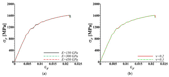
Figure 13.
Effect of the elastic properties, (a) Young’s modulus and (b) Poisson’s ratio, of an inclusion of strength MPa ( and ) on the macroscopic flexural stress ()-strain () response of the dual-phase steel.
Furthermore, our supervised machine learning based analysis helped unravel the effects of the multivariable input space on the bendability of both single-phase and dual-phase materials. In particular, the machine learning based analysis shows that the inclusion size and location, and (to an extent) strength of the inclusion are the key features that affect the bendability of a simple single-phase material with a subsurface inclusion. On the contrary, the effect of an inclusion on the bendability of the dual-phase steel is more complex. The machine learning based analysis clearly highlights the extremely non-linear and oftentimes discrete effect of the individual features associated with the inclusion on the bendability of the dual-phase steel. The machine learning based analysis also shows that the bendability of a dual-phase steel is not only affected by the size, shape, location and (to an extent) strength of the subsurface inclusion but it is also affected by the underlying dual-phase microstructure. The latter implies that even for a fixed size, shape, location and strength of a subsurface inclusion, the sample to sample variation in the size of ferrite and martensite phases can cause a difference in the fracture response under bending.
The industrial scale V-bend tests of the dual-phase steel sheets revealed significant sample to sample variation in the bendability of the steel which was associated with the size and location of the sub-surface inclusion in the specimens, Figure 1d. In particular, a pronounced inclusion size effect on the bendability of the steel sheet was noted. The bendability of the steel sheet in the industrial tests was characterized by the presence or absence of cracks on the tension side of the V-bent specimens, Figure 14a. However, this criterion cannot be directly applied to our microstructure-based finite element calculations to analyze the effect of inclusion size and location on the bendability of the dual-phase steel. This is due to the various simplifying assumptions in our computational method that were invoked to make these expensive microstructure-based finite element calculations possible. These simplifying assumptions include, (i) modeling a smaller specimen geometry and imposing relatively higher loading rate, (ii) modeling only a 2D slice of the material microstructure, (iii) modeling a single inclusion that is always located in the center along the length of the bend specimen which constitutes a worst-case scenario, and (iv) choice of the constitutive parameters associated with the damage model for the constituent phases that were not calibrated for the steel under consideration but were chosen to artificially accelerate the damage process in the material. Thus, we simply assume that a dual-phase steel specimen with an inclusion in the calculations passes the quality control test if the normalized macroscopic flexural strain to failure, , is greater than or equal to a critical value, c. In other words, we assume that if the weakening effect of an inclusion on the bendability of the dual-phase steel is less than then the steel passes the quality control test despite the presence of an inclusion. Next, we scale the size of the 2D inclusion modeled as following the works of refs. [47,48] to approximate the weakening effect of an equivalent 3D inclusion.
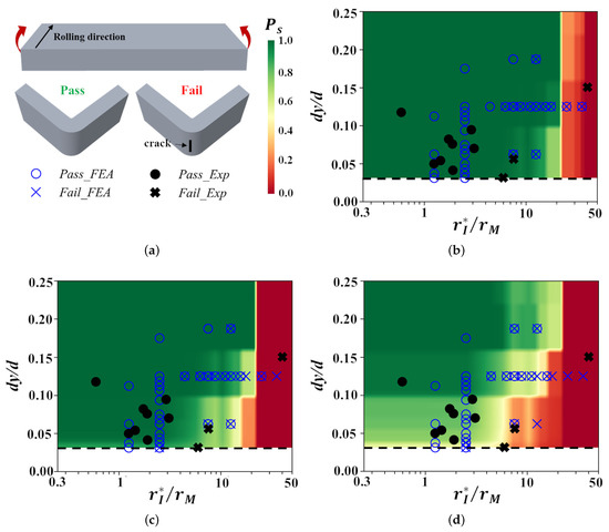
Figure 14.
(a) Schematic of a bend specimen, and examples of ‘pass’ and ‘fail’ characterization during V-bend tests. (b–d) The effects of the normalized location, , and normalized size, , of the subsurface inclusion on the bendability of an advanced high strength, DP1000, dual-phase steel as characterized by V-bend tests (), and as predicted by microstructure-based finite element calculations () and supervised machine learning model (contour plot of the probability of survival, ). In the finite element calculations and machine learning model, a dual-phase steel specimen with an inclusion passes the bend test if the value of the normalized macroscopic flexural strain to failure, (b) , (c) or (d) .
Figure 14b–d show the effects of the normalized location, , and size, , of a subsurface inclusion on the bendability of the dual-phase steel as characterized by V-bend tests () and as predicted by the microstructure-based finite element calculations () considering the values of , and , respectively. In Figure 14b–d, finite element results corresponding to a range of values of the inclusion strength and aspect ratio, as well as multiple realizations of the underlying dual-phase microstructures are superimposed on top of each other in the versus space. The contour plots in Figure 14b–d are the probability of survival, , as a function of and obtained from the trained supervised machine learning model. The value of is estimated as,
where, N is the total number of samples with fixed set of values of and . For a fixed set of values of and , random samples are analyzed with the values of the remaining parameters of the feature set 2 in Table 3 lying within a lower and an upper bound (, , , , ). The results presented in Figure 14b–d, clearly highlight the strong and somewhat discrete inclusion size effect on the bendability of the dual-phase advanced high strength steel that naturally emerge in our calculations. The very good quantitative correlation between the predictions for and the limited experimental results in Figure 14c is likely serendipitous as we had no a priori reason to expect a quantitative correlation between the results of the industrial scale tests and the microstructure-based finite element calculations. Nevertheless, these results clearly show that refining the inclusion size relative to the size of the martensite phase can significantly decrease the detrimental effect of the inclusions on the bendability of the advanced high strength dual-phase steel sheets.
7. Conclusions
Microstructure-based finite element calculations were carried out to understand the effects of the length-scales induced by the mode of deformation, i.e., V-bending, ‘intended’ dual-phase ferritic-martensitic microstructure, and ‘unintended’ microstructural features, i.e., inclusions on ductile crack nucleation and early stage crack growth in an advanced high strength dual-phase steel. In the calculations, the inclusion modeled was always located in the center along the length of the bend specimens and parametric studies were carried out to explore the effects of inclusion size, shape, location (along the thickness of the specimen) and properties on the bendability of the dual-phase steel. In line with the experimental observations, strong inclusion size effect on the bendability of the dual-phase steel naturally emerge in the calculations. The effects of the multivariable input space associated with both the ‘intended’ and ‘unintended’ microstructural features on the bendability of the dual-phase steel were also quantified using supervised machine learning. The supervised machine learning approach used here utilized an ensemble learning method for regression analysis. For the purpose of comparison and to gain additional insight, the effect of an inclusion on the bendability of a single-phase material with constitutive parameters corresponding to the overall ‘homogenized’ dual-phase steel under consideration were also analyzed.
The key conclusions are as follows:
- 1.
- A subsurface void nucleation at an inclusion in a single-phase material under V-bending results in plastic strain localization in bands emanating from the subsurface void that are oriented at with respect to the loading axis. Finally, with continued bending the ligament between the surface and the subsurface void parallel to the loading axis undergoes ductile fracture post-localized thinning.
- 2.
- The micro-mechanism of ductile fracture in a dual-phase steel with a subsurface inclusion under V-bending not only differs from that in a single-phase material but also strongly depends on the inclusion size and location:
- (a)
- In a dual-phase steel with a subsurface inclusion of size sufficiently greater than the martensite phase and/or located rather close to the free-surface, plastic strain localizes in an inclined band emanating from the free-surface towards the subsurface void nucleated at the inclusion. Finally, with continued bending, a ductile fracture occurs along the localization band.
- (b)
- In a dual-phase steel with a subsurface inclusion of size comparable to (or less than) the martensite phase and/or located sufficiently away from the free-surface, plastic strain localizes in inclined bands emanating from the free-surface that ignore the subsurface void nucleated at the inclusion. Finally, with continued bending ductile fracture occurs along the localization band while ignoring the subsurface void nucleated at the inclusion.
- 3.
- The supervised machine learning analysis revealed that, unlike a single-phase material, the bendability of a dual-phase steel with a subsurface inclusion is not only affected by the features associated with the inclusion but also by the features associated with the underlying dual-phase microstructure. Thus, efforts to reduce the sample to sample variation in the bendability of a dual-phase steel should focus on both the inclusions and the underlying material microstructure.
- 4.
- Our results show that there exists a critical size of the inclusion relative to the size of the martensite phase below which the detrimental effect of the inclusion on the bendability of the dual-phase steel vanishes. Thus, instead of trying to get rid of every inclusion from the steel, which is extremely difficult and expensive, efforts can be directed towards refining the inclusion size.
Author Contributions
Conceptualization, D.F. and A.S.; methodology, Y.L. and A.S.; validation, Y.L., D.F., R.A. and A.S.; investigation, Y.L. and D.F.; formal analysis, Y.L., D.F., R.A. and A.S.; data curation, Y.L. and A.S.; writing—original draft preparation, Y.L. and A.S.; writing—review and editing, Y.L., D.F., R.A. and A.S.; supervision, A.S.; funding acquisition, D.F. and A.S. All authors have read and agreed to the published version of the manuscript.
Funding
This research was financially supported by the ArcelorMittal Global R&D, East Chicago, IN, USA, and U.S. National Science Foundation grant CMMI-1663130.
Institutional Review Board Statement
Not applicable.
Informed Consent Statement
Not applicable.
Data Availability Statement
Data is contained within the article.
Acknowledgments
The large-scale finite element calculations reported on were carried out using high performance research computing resources provided by Texas A&M University. The authors are very grateful for the many fruitful discussions with Shrikant P. Bhat, Narayan S. Pottore, Pallava Kaushik and Gang Huang of ArcelorMittal Global R&D, East Chicago, IN, USA.
Conflicts of Interest
The authors declare no conflict of interest.
References
- Joost, W.J. Reducing vehicle weight and improving US energy efficiency using integrated computational materials engineering. Jom 2012, 64, 1032–1038. [Google Scholar] [CrossRef]
- Kuziak, R.; Kawalla, R.; Waengler, S. Advanced high strength steels for automotive industry. Arch. Civ. Mech. Eng. 2008, 8, 103–117. [Google Scholar] [CrossRef]
- Davies, G. Materials for Automobile Bodies; Butterworth-Heinemann: Oxford, UK, 2012. [Google Scholar]
- Rashid, M. Dual phase steels. Annu. Rev. Mater. Sci. 1981, 11, 245–266. [Google Scholar] [CrossRef]
- Bhattacharya, D. Metallurgical perspectives on advanced sheet steels for automotive applications. In Advanced Steels; Springer: Berlin/Heidelberg, Germany, 2011; pp. 163–175. [Google Scholar]
- Thornton, P. The influence of nonmetallic inclusions on the mechanical properties of steel: A review. J. Mater. Sci. 1971, 6, 347–356. [Google Scholar] [CrossRef]
- Maire, E.; Bouaziz, O.; Di Michiel, M.; Verdu, C. Initiation and growth of damage in a dual-phase steel observed by X-ray microtomography. Acta Mater. 2008, 56, 4954–4964. [Google Scholar] [CrossRef]
- Landron, C.; Bouaziz, O.; Maire, E.; Adrien, J. Characterization and modeling of void nucleation by interface decohesion in dual phase steels. Scr. Mater. 2010, 63, 973–976. [Google Scholar] [CrossRef]
- Landron, C.; Maire, E.; Bouaziz, O.; Adrien, J.; Lecarme, L.; Bareggi, A. Validation of void growth models using X-ray microtomography characterization of damage in dual phase steels. Acta Mater. 2011, 59, 7564–7573. [Google Scholar] [CrossRef]
- Kadkhodapour, J.; Butz, A.; Ziaei-Rad, S.; Schmauder, S. A micro mechanical study on failure initiation of dual phase steels under tension using single crystal plasticity model. Int. J. Plast. 2011, 27, 1103–1125. [Google Scholar] [CrossRef]
- Bareggi, A.; Maire, E.; Bouaziz, O.; Di Michiel, M. Damage in dual phase steels and its constituents studied by X-ray tomography. Int. J. Fract. 2012, 174, 217–227. [Google Scholar] [CrossRef]
- Choi, S.H.; Kim, E.Y.; Woo, W.; Han, S.; Kwak, J. The effect of crystallographic orientation on the micromechanical deformation and failure behaviors of DP980 steel during uniaxial tension. Int. J. Plast. 2013, 45, 85–102. [Google Scholar] [CrossRef]
- Han, Q.; Kang, Y.; Hodgson, P.D.; Stanford, N. Quantitative measurement of strain partitioning and slip systems in a dual-phase steel. Scr. Mater. 2013, 69, 13–16. [Google Scholar] [CrossRef]
- Chen, P.; Ghassemi-Armaki, H.; Kumar, S.; Bower, A.; Bhat, S.; Sadagopan, S. Microscale-calibrated modeling of the deformation response of dual-phase steels. Acta Mater. 2014, 65, 133–149. [Google Scholar] [CrossRef]
- Tasan, C.C.; Hoefnagels, J.P.; Diehl, M.; Yan, D.; Roters, F.; Raabe, D. Strain localization and damage in dual phase steels investigated by coupled in-situ deformation experiments and crystal plasticity simulations. Int. J. Plast. 2014, 63, 198–210. [Google Scholar] [CrossRef]
- Lai, Q.; Bouaziz, O.; Gouné, M.; Brassart, L.; Verdier, M.; Parry, G.; Perlade, A.; Bréchet, Y.; Pardoen, T. Damage and fracture of dual-phase steels: Influence of martensite volume fraction. Mater. Sci. Eng. A 2015, 646, 322–331. [Google Scholar] [CrossRef]
- Gerbig, D.; Srivastava, A.; Osovski, S.; Hector, L.G.; Bower, A. Analysis and design of dual-phase steel microstructure for enhanced ductile fracture resistance. Int. J. Fract. 2018, 209, 3–26. [Google Scholar] [CrossRef]
- Zheng, X.; Ghassemi-Armaki, H.; Srivastava, A. Structural and microstructural influence on deformation and fracture of dual-phase steels. Mater. Sci. Eng. A 2020, 774, 138924. [Google Scholar] [CrossRef]
- Sun, X.; Choi, K.S.; Soulami, A.; Liu, W.N.; Khaleel, M.A. On key factors influencing ductile fractures of dual phase (DP) steels. Mater. Sci. Eng. A 2009, 526, 140–149. [Google Scholar] [CrossRef]
- De Geus, T.; Peerlings, R.; Geers, M. Microstructural topology effects on the onset of ductile failure in multi-phase materials–A systematic computational approach. Int. J. Solids Struct. 2015, 67, 326–339. [Google Scholar] [CrossRef]
- Matsuno, T.; Teodosiu, C.; Maeda, D.; Uenishi, A. Mesoscale simulation of the early evolution of ductile fracture in dual-phase steels. Int. J. Plast. 2015, 74, 17–34. [Google Scholar] [CrossRef]
- Zhou, J.; Gokhale, A.M.; Gurumurthy, A.; Bhat, S.P. Realistic microstructural RVE-based simulations of stress–strain behavior of a dual-phase steel having high martensite volume fraction. Mater. Sci. Eng. A 2015, 630, 107–115. [Google Scholar] [CrossRef]
- De Geus, T.; van Duuren, J.; Peerlings, R.; Geers, M. Fracture initiation in multi-phase materials: A statistical characterization of microstructural damage sites. Mater. Sci. Eng. A 2016, 673, 551–556. [Google Scholar] [CrossRef]
- Liu, Y.; Fan, D.; Bhat, S.P.; Srivastava, A. Ductile fracture of dual-phase steel sheets under bending. Int. J. Plast. 2020, 125, 80–96. [Google Scholar] [CrossRef]
- Uthaisangsuk, V.; Prahl, U.; Bleck, W. Characterisation of formability behaviour of multiphase steels by micromechanical modelling. Int. J. Fract. 2009, 157, 55. [Google Scholar] [CrossRef]
- Uthaisangsuk, V.; Prahl, U.; Bleck, W. Modelling of damage and failure in multiphase high strength DP and TRIP steels. Eng. Fract. Mech. 2011, 78, 469–486. [Google Scholar] [CrossRef]
- Srivastava, A.; Bower, A.; Hector Jr, L.; Carsley, J.; Zhang, L.; Abu-Farha, F. A multiscale approach to modeling formability of dual-phase steels. Model. Simul. Mater. Sci. Eng. 2016, 24, 025011. [Google Scholar] [CrossRef]
- Ayatollahi, M.; Darabi, A.C.; Chamani, H.; Kadkhodapour, J. 3D micromechanical modeling of failure and damage evolution in dual phase steel based on a real 2D microstructure. Acta Mech. Solida Sin. 2016, 29, 95–110. [Google Scholar] [CrossRef]
- Li, Z.; Guo, W. The influence of plasticity mismatch on the growth and coalescence of spheroidal voids on the bimaterial interface. Int. J. Plast. 2002, 18, 249–279. [Google Scholar] [CrossRef]
- Frómeta, D.; Lara, A.; Molas, S.; Casellas, D.; Rehrl, J.; Suppan, C.; Larour, P.; Calvo, J. On the correlation between fracture toughness and crash resistance of advanced high strength steels. Eng. Fract. Mech. 2019, 205, 319–332. [Google Scholar] [CrossRef]
- Sriram, S.; Wong, C.; Huang, M.; Yan, B. Stretch bendability of advanced high strength steels (SAE Transactions No. 2003-01-1151). J. Mater. Manuf. 2003, 112, 641–649. [Google Scholar]
- Fan, D.; Kaushik, P.; Pielet, H. Bend Failure Mechanism of Zinc Coated Advanced High Strength Steel. ISIJ Int. 2018, 58, 1538–1544. [Google Scholar] [CrossRef]
- Kadkhodapour, J.; Butz, A.; Rad, S.Z. Mechanisms of void formation during tensile testing in a commercial, dual-phase steel. Acta Mater. 2011, 59, 2575–2588. [Google Scholar] [CrossRef]
- Samei, J.; Zhou, L.; Kang, J.; Wilkinson, D.S. Microstructural analysis of ductility and fracture in fine-grained and ultrafine-grained vanadium-added DP1300 steels. Int. J. Plast. 2019, 117, 58–70. [Google Scholar] [CrossRef]
- Srivastava, A.; Ponson, L.; Osovski, S.; Bouchaud, E.; Tvergaard, V.; Needleman, A. Effect of inclusion density on ductile fracture toughness and roughness. J. Mech. Phys. Solids 2014, 63, 62–79. [Google Scholar] [CrossRef]
- Srivastava, A.; Osovski, S.; Needleman, A. Engineering the crack path by controlling the microstructure. J. Mech. Phys. Solids 2017, 100, 1–20. [Google Scholar] [CrossRef]
- Liu, Y.; Zheng, X.; Osovski, S.; Srivastava, A. On the micromechanism of inclusion driven ductile fracture and its implications on fracture toughness. J. Mech. Phys. Solids 2019, 130, 21–34. [Google Scholar] [CrossRef]
- MATLAB. Image Processing Toolbox; The MathWorks Inc.: Natick, MA, USA, 2017. [Google Scholar]
- Gurson, A.L. Plastic Flow and Fracture Behavior of Ductile Materials Incorporating Void Nucleation, Growth and Coalescence. Ph.D. Thesis, Brown University, Providence, RI, USA, 1975. [Google Scholar]
- Tvergaard, V.; Needleman, A. Analysis of the cup-cone fracture in a round tensile bar. Acta Metall. 1984, 32, 157–169. [Google Scholar] [CrossRef]
- Chu, C.; Needleman, A. Void nucleation effects in biaxially stretched sheets. J. Eng. Mater. Technol. 1980, 102, 249–256. [Google Scholar] [CrossRef]
- Tvergaard, V. Influence of voids on shear band instabilities under plane strain conditions. Int. J. Fract. 1981, 17, 389–407. [Google Scholar] [CrossRef]
- Tvergaard, V. On localization in ductile materials containing spherical voids. Int. J. Fract. 1982, 18, 237–252. [Google Scholar]
- Pan, J.; Saje, M.; Needleman, A. Localization of deformation in rate sensitive porous plastic solids. Int. J. Fract. 1983, 21, 261–278. [Google Scholar] [CrossRef]
- Freund, R.J.; Wilson, W.J.; Sa, P. Regression Analysis; Elsevier: Amsterdam, The Netherlands, 2006. [Google Scholar]
- Friedman, J.H. Greedy function approximation: A gradient boosting machine. Ann. Stat. 2001, 29, 1189–1232. [Google Scholar] [CrossRef]
- Aravas, N.; McMeeking, R. Finite element analysis of void growth near a blunting crack tip. J. Mech. Phys. Solids 1985, 33, 25–49. [Google Scholar] [CrossRef]
- Hom, C.L.; McMeeking, R.M. Three-dimensional void growth before a blunting crack tip. J. Mech. Phys. Solids 1989, 37, 395–415. [Google Scholar] [CrossRef]


Publisher’s Note: MDPI stays neutral with regard to jurisdictional claims in published maps and institutional affiliations. |
© 2021 by the authors. Licensee MDPI, Basel, Switzerland. This article is an open access article distributed under the terms and conditions of the Creative Commons Attribution (CC BY) license (http://creativecommons.org/licenses/by/4.0/).