Abstract
The very recently developed coarse-grained new-generation oxide dispersion strengthened (ODS) alloys containing 5 vol.% homogeneously distributed yttrium nano-precipitates seems to be a promising oxidation-resistant structural material for applications at temperatures above 1000 °C. The primary aim of the present paper is the introduction of the new-generation oxide dispersion strengthened (ODS) alloy and the first testing of its high temperature fatigue properties at 800 °C, concurrently demonstrating a novel and very efficient methodology by using an incremental fatigue step test. The successful application of the methodology motivates the authors to test the fatigue properties of new generation ODS alloys at 1000–1200 °C in the near future.
1. Introduction
Oxide dispersion-strengthened (ODS) alloys containing homogeneously dispersed yttrium nanoparticles allows for the operation limit of structural materials to be increased to very high temperatures of up to 1300 °C. The thermally very stable nano-oxides act as obstacles to the movement of dislocations in the matrix and thus contribute to the strengthening within a very wide range of temperatures. In the case of classical ODS alloys, usually, a small amount (about 0.3 wt.%) of homogeneously dispersed yttrium nano-sized particles is used [1,2]. Furthermore, strategies based on the addition of complex oxides (Y, Hf, Zr, Ce, La) for the enhancement of strengthening ODS EUROFER steel can be found in the literature (see [3] and references therein). The mechanism of strengthening by yttrium nano-oxides has also been investigated for other complex materials. Hadraba et al. [4] investigated the effect of oxide dispersion on the strength properties of CoCrFeNiMn high entropy alloy in detail and confirmed the positive effect of the dislocation pinning mechanism of nano-oxides at room and elevated temperatures.
Yttrium particles are introduced to ODS materials by the powder metallurgy route. As reported in detail by Svoboda et al. (see e.g., [5]), during mechanical alloying (MA), the heavily deformed matrix of the prepared powder contains a very high density of defects acting as traps for oxygen, and, therefore, up to 5 at. % of oxygen (several orders of magnitude more than in the defect-free system) can be dissolved in the powder matrix. The theoretical explanation for this rather surprising phenomenon is presented in [6]. This inspired us to develop a class of new-generation ODS alloys strengthened by yttrium nano-precipitates of the volume fraction up to 5%.
The new-generation ODS alloys are prepared in three processing steps:
- mechanical alloying of the input powders in an evacuated attritor for a sufficient time to achieve sufficient homogenization and saturation of the properties;
- full consolidation of canned powders by hot rolling, provoking an intensive repeated dynamic recrystallization leading to an ultra-fine grained (100–150 nm) microstructure; and
- annealing of the consolidated alloy to provoke secondary recrystallization leading to drastic coarsening of grains (200–500 μm) by keeping a rather fine dispersion of the nano-oxides (15–30 nm) in the grains.
It should be pointed out that the dynamic recrystallization provoked by hot rolling significantly decreases the density of defects in the matrix and causes a significant supersaturation of the lattice by oxygen. This causes spontaneous precipitation of nano-oxides with a size of about 5 nm during hot rolling, where the phenomenon can be termed as recrystallization induced precipitation.
Most experiments in the literature concerning ODS alloys have focused mainly on the description of the microstructure evolution at elevated temperature [5,7,8], tensile tests [9], and creep properties [10], but results concerning the fatigue behavior are rather rare. The effect of cyclic loading was monitored in [11] using the three-point bending fatigue test at cycle asymmetry ratio R = 0.1 at ambient temperature. The microstructural stability of ODS steels exposed to cyclic loading at temperatures up to 750 °C was published in [8].
The basic cyclic stress–strain curve (CSSC) is most often evaluated from the constant strain amplitude test or constant plastic strain amplitude test on a set of specimens loaded at different levels. In fatigue tests with constant amplitude loading, the material response to the cyclic loading often tends to stabilize (i.e., an initial period of rapid hardening or softening is followed by saturation). In the case that saturation is not completed until specimen fracture, some reasonable values are taken, for example, values at half-life [12].
In addition to the basic CSSC, a short-cut procedure known as the incremental fatigue step test can be adopted for an experimental determination of CSSC. The main advantage of this procedure is the possibility of using only a single specimen. According to [13,14], the incremental CSSC did not differ from the CSSC obtained on several specimens for copper, low-carbon steels, or nickel-based superalloys. Petrenec [15] and Smid [14] investigated two types of Inconel (738LC and 792-5A) cyclically strained at 23 °C and 800 °C within the blocks of cycles with step-wise increasing strain amplitudes and, subsequently, the stress–strain response of the Inconel was analyzed. Parameters of CSSC determined by using the short-cut procedure are in good agreement with the parameters of the standard CSSC at both used temperatures.
The main aim of this paper was to introduce a new-generation of ODS alloys containing a high volume fraction of yttrium nano-precipitates prepared by mechanical alloying and to demonstrate its high temperature cyclic plastic response. The fatigue characteristics served as a preliminary check of the material performances at high temperature in comparison with conventionally produced materials. Results of the incremental fatigue step test were accompanied by microstructural characterization and fractographic analysis. The results obtained at 800 °C were found to be quite promising.
2. Materials and Methods
Material: The chemical composition of the material under investigation was Fe–10Al–4Y2O3, and it was produced in three processing steps: mechanical alloying (MA) of the powder, hot consolidation of the powder by rolling, and secondary recrystallization. The powders were prepared from the powders of individual components in a self-made ball mill by MA for a sufficient time (approx. eight days). The milling balls of the diameter of 40 mm were made from low-carbon maraging 350 steel to minimize contamination of the powders by carbon due to abrasion of the balls. A small content of Ni and Co (contained in the maraging steel) in the powder after MA indicated that 2–3% of the powder originated from the continuous abrasion of the milling balls. After MA, the powder was poured under protective gas (CO2) and cold compacted into a rolling container from a low alloyed steel tube with a 20 mm diameter and 1 mm wall thickness. Then, the rolling container was evacuated, sealed by welding, and rolled at 960 °C in three steps to the thicknesses of 7.5 mm, 4.9 mm, and 3.25 mm. The mean strain rate during hot rolling was estimated to be 10 s−1. After the hot consolidation, the ODS alloy was stripped from the rolling container and annealed at 1200 °C for 4 h to achieve the required coarse-grained microstructure with homogeneously dispersed nano-oxides by secondary recrystallization. The kinetics of microstructure evolution during secondary recrystallization after hot rolling in similar systems was determined in [5,7].
Hardness: Hardness of the coarse-grained microstructure after annealing was measured using a Vickers indenter loaded with a force corresponding to 5 kg weight (ZwickRoell ZHV30 Vickers Hardness Tester, ZwickRoell GmbH, Ulm, Germany).
Specimen: For the incremental fatigue step test, a flat dog-bone-shaped specimen was used. The specimen was shaped by spark erosion with the axis parallel to the rolling direction (see Figure 1). The final specimen thickness of 2.4 mm was achieved by grinding.
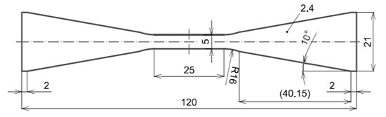
Figure 1.
Dimensions (in mm) and shape of the flat dog-bone specimen for fatigue testing.
Loading: The incremental fatigue step test was conducted in a fully reversed total strain cycle (Rε = −1) (i.e., in symmetric tension-compression at 800 °C in air). To avoid the buckling of the flat dog-bone-shaped specimen during the compression part of the loading cycle, special anti-buckling fixtures were used. The incremental fatigue step test was performed under strain control using a computer-controlled electro-hydraulic testing system MTS 810. The strain rate of 2 × 10⁻³ s−1 was kept constant. The individual levels of total strain amplitude were stepwise increased from 0.1% to 0.6%. The number of cycles at each strain level was set to 100. The number of cycles at the last strain level (0.6%) of the incremental fatigue step test reached 84. The increase of the strain amplitude for the successive block was performed during the tensile phase of the loading. An MTS extensometer with a gauge length of 12 mm was used for measurement and control of the strain.
Microstructure characterization: The observation of the microstructure and fracture surface of the fatigued specimen was performed using a scanning electron microscope (SEM) LYRA 3 XMU FEG/SEM x FIB (TESCAN, Brno, Czech Republic). Metallographic samples were prepared by mechanical–chemical polishing using a colloidal silica emulsion. The plain of the samples was parallel to the rolling plane. Evaluation of the average grain size was performed using the linear interception method according to the ASTM E112-13 standard. The surface oxide layer created during fatigue testing at 800 °C was analyzed using a SEM equipped with an X-Max80 energy dispersive X-ray (EDX) (Oxford Instruments, High Wycombe, UK) detector.
The internal microstructure of the material was also characterized by high-resolution transmission electron microscope (TEM) JEOL JEM-2100F (JEOL Ltd., Tokyo, Japan) with a field emission gun (FEG) electron source equipped with bright field (BF) and high-angle annular dark-field (HAADF) detectors for observation in scanning mode (STEM). TEM foils were prepared from the ground discs of approximately 60–80 μm in thickness, which were electrolytically polished by a solution of 5% perchloric acid and 95% acetic acid at the temperature of 14 °C. The foil plane was parallel to the plain of hot rolling.
3. Results and Discussion
The microstructure of the material under investigation is shown in Figure 2. There were no changes observed in the microstructure before and after the termination of the fatigue test at 800 °C. The material had a non-uniform fine to coarse-grained structure (see overview in Figure 2a). The grain size varied from approximately 20 μm to nearly 300 μm. The average grain size evaluated on approximately 500 grains using the linear interception method was 129 μm. The grain boundaries were strongly wrinkled (see Figure 2b). The particles with a size up to 1 μm observed on the metallographic cross section (see spots in Figure 2b) and TEM foil (Figure 2c) were analyzed by EDX and evaluated as Al nitrides. In the presented study, neither the SEM nor TEM investigations provided any evidence of the detrimental effect of Al nitrides on the fatigue behavior of the investigated ODS alloy. The nitrides stemmed from the nitrogen involved in the Fe powder used for the production of the ODS powder by mechanical alloying. The Al nitrides coarsened significantly during secondary recrystallization, where one could appreciate the drastic difference between the coarsening kinetics of AlN and Y2O3 precipitates.
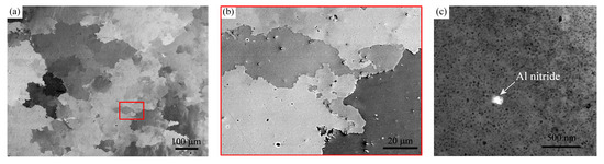
Figure 2.
Scanning electron microscopy (SEM) micrograph (in BSE) of the microstructure of ODS alloy tested at 800 °C (a) overview; (b) detail of area in red rectangle in higher magnification; (c) STEM micrograph showing Y2O3 nanoparticles and occasional Al nitride particle.
The occurrence of pores was only very occasional (not presented here), in other words, the compaction of the powder achieved by hot rolling was satisfactory. For a similar material system studied in [7] (i.e., for the alloy with ferritic Fe-10Al matrix strengthened with fine alumina dispersion), the evolution of grain coarsening during annealing was related to Vickers hardness HV5. Significant increase in grain size was accompanied by a considerable decrease in hardness. The material with the final grain size of 45 μm exhibited a Vickers hardness HV5 of 320. Material studied in this work contained grains approximately three times larger (i.e., mean grain size (evaluated by linear interception method) was approximately 129 μm), nevertheless, the Vickers hardness HV5 reached the value of almost 380. The bigger grain size, together with very fine oxide dispersion, seems to be positive also from the point of view of creep properties because fine-grained ODS steels exhibit generally much worse creep properties than coarse-grained ones (see [16]).
The internal microstructure of the new-generation ODS alloy after fatigue loading was studied using TEM (see Figure 3) in scanning mode. Figure 3a shows an overview of the microstructure with a high quantity of nano-particles of spherical shape homogeneously distributed in the material (detail of nano-sized yttrium particles with the size of approximately 25 nm in the inlet in the left corner). The amount of Y2O3 nanoparticles was significantly higher than that reported in the literature because of the presence of 4 wt.% of Y2O3 compared to the typical 0.25 wt.% for previously reported ODS steels [1,2]. Figure 3b shows a microstructure after fatigue loading (incremental step test) in higher magnification where reinforcing yttrium nanoparticles were present together with dislocations (marked by white arrows). Dislocations were observed with the electron beam vector parallel to the [010] zone axis. This indicates that the dislocation structure of the density to the order of magnitude 1014 m−2 developed in the grains during the fatigue experiment.
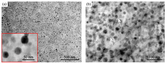
Figure 3.
STEM micrographs of the ODS alloy (BF): (a) an overview and detail of Y2O3 nano-particles in the left corner insertion; (b) dislocations (marked by white arrows) could be observed under certain diffraction conditions–B = [010] in the material after fatigue test termination.
The chemical composition of nano-sized spherical particles from Figure 3b was further analyzed using STEM-EDX mapping, which confirmed the yttrium nanoparticles as the dominant strengthening agent (see Figure 4).
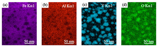
Figure 4.
STEM-EDX mapping of reinforcing Y2O3 nano-particles. The low contrast of Fe (a) and Al (b) mapping is due to their high content in the matrix and the foil thickness significantly exceeding the size of the yttrium-oxides (c). The low contrast of O (d) is due to the overlap of the O peak with peaks of other elements.
During fatigue loading, the individual levels of total strain amplitude were increased from 0.1% to 0.6%. The number of cycles in the block for each strain level was set to 100. The recorded stress amplitude was then plotted in the dependence on the applied number of cycles (see Figure 5a). At the last level of stress amplitude (i.e., at the stress for the strain amplitude εa = 0.6%), the number of cycles to fracture reached the value of 84. Fatigue loading at 800 °C resulted in a stable stress response in all tested strain levels (i.e., neither hardening nor softening was observed), and therefore according to [17], the final data points can be used for the construction of the CSSC. The same character of fatigue response (i.e., neither hardening nor softening) was observed when the plastic strain amplitude εap was evaluated from the saturated hysteresis loops. These data are plotted in the dependence on the number of applied cycles (see Figure 5b).
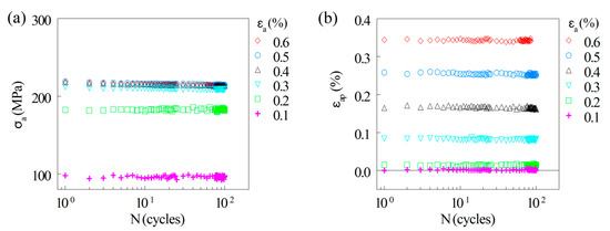
Figure 5.
(a) Stress amplitude vs. the number of applied cycles in loading with increasing total strain amplitudes at 800 °C. (b) Dependence of evaluated plastic strain amplitude on the number of cycles.
Saturated hysteresis loops at the end of each block of strain amplitude were recorded and evaluated. Figure 6 shows a comparison of hysteresis loops for the selected total strain amplitudes. At the smallest applied strain amplitude (0.1%-Figure 6a), the material showed nearly pure elastic behavior, whereas the medium strain amplitude (0.3%, Figure 6b) and the highest strain amplitude (0.6%, Figure 6c) presented rather pronounced elastoplastic behavior.
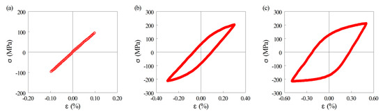
Figure 6.
Saturated hysteresis loops for three different applied strain amplitudes: (a) εa = 0.1%; (b) εa = 0.3%; (c) εa = 0.6%.
A short-cut procedure was applied according to the work of Polák [17] with very similar conclusions. The saturated values of stress and strain amplitudes were achieved and the final data points from the saturated hysteresis loops were used for the construction of the incremental CSSC. Figure 7 shows the dependence of the stress amplitude on the plastic strain amplitude of the 100th hysteresis loop in each block of the short-cut procedure. To judge the high temperature behavior of the new-generation ODS alloy, the data of the CSSC for Inconel 738LC, being highly resistant to cyclic loading at 800 °C [15], are also presented (dashed line in Figure 7). From the comparison, it is evident that the CSSC for the ODS alloy was below the CSSC for Inconel 738LC and the shift in the values of stress amplitude was between 200 MPa and 400 MPa for the lowest and highest plastic strain amplitudes, respectively. It should be mentioned that Ni-based superalloys are strengthened by ordered cube-shaped γ’precipitates exhibiting instabilities due to coalescence [18] and coarsening [19] at a temperature above 900 °C. This is not the case of ODS steels containing very stable Y-based oxides and thus they are preferred for applications at temperatures over 1000 °C [16]. The difference between the CSSC data for the investigated new-generation ODS alloy and Inconel [15] is therefore not crucial. Moreover, the saturation of the stress amplitude and the ability to absorb a significant amount of the cumulative plastic strain indicates promising reliability (resistance against brittle fracture) and possible hot workability of the new-generation ODS alloy at 800 °C.
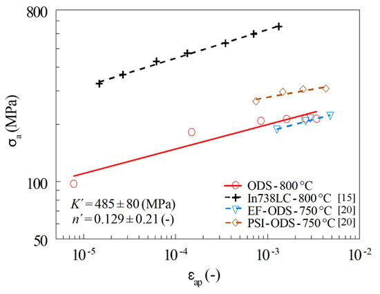
Figure 7.
Cyclic Stress Strain Curve (CSSC) obtained using incremental step test method for the ODS alloy and comparison with similar results for Inconel 738 LC [15] and CSSCs for two types of ODS steels (ferritic–martensitic EF–ODS and ferritic PSI–ODS) [20].
In order to compare the studied new-generation ODS alloy with other ODS steels, CSSCs determined for two types of ODS material (i.e., ODS Eurofer (EF-ODS), tempered ferritic–martensitic steel and ODS ferritic steel (PSI–ODS) presented by Kuběna [20]) were incorporated into the plot in Figure 7. The CSSC of ferritic–martensitic steel (EF–ODS) shifted to lower stress amplitudes than the CSSC of the ODS material under investigation, but the vice versa was true for ferritic steel (PSI–ODS). Both dependencies published in [20] were nevertheless obtained at the test temperature of 750 °C. If the difference of testing temperature had been taken into account, we can expect that the new-generation ODS alloy investigated in this paper may have comparable or even better properties than EF–ODS and PSI–ODS.
After the test termination (i.e., fracture of the specimen), both the surface of the gauge length and fracture surface were observed and the SEM micrographs are shown in Figure 8. On a macroscopic scale (see Figure 8a), the fracture surface exhibited a rough profile. In the left part of Figure 8a, one can see a side view of the specimen, where a highly pronounced necking caused by a high plastic strain in the last level of the incremental step test (εa = 0.6%) is visible. A top view on the rough fracture reveals a surface exhibiting ductile fracture with a high number of V-shaped troughs or tongue like features arranged into the almost lamellar pattern in the right part of Figure 8a. This feature could be attributed to the method of material processing, leading to large pan-cake grains parallel to the rolling plane. This layered structure then forms a lamellar pattern at the fracture surface. In contrast, the fracture surface of conventional ductile materials in the form of sheets usually has a roof-like pattern (see [21]). A micrograph with a higher magnification of tongues marked by the green rectangle is presented in Figure 8b. The surface of the gauge length (see red rectangle in Figure 8a) exhibits the wavelike pattern shown in Figure 8c. This pattern originated from the expressive plastic deformation of the necking area with the slightly oxidized surface. During the fatigue test at 800 °C, the specimen was exposed to a high temperature in air for a few hours, and a brittle thin layer of oxides was not able to deform in the same way as the ductile substrate of the ODS alloy. Details of the oxide layer with a wavy pattern present on a highly deformed area of specimen necking is shown in Figure 8e. Ductile dimples with spherical particles deposited at the bottoms of the dimples can be observed in the middle part of Figure 8d. Similar dimples were also detectable on the sides of the tongues at higher magnification (see Figure 8f). The presence of Al nitrides was not detected on the fracture surface of the investigated ODS steel (i.e., they do not play an important role in the initiation or propagation of fatigue crack).
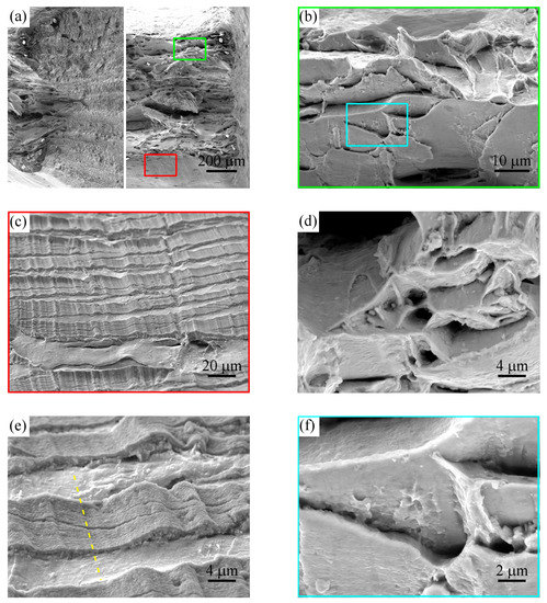
Figure 8.
The fracture surface of the sample loaded using the incremental step test where the fracture occurred after 84 cycles at the highest level of strain amplitude (εa = 0.6%): (a) overview in macroscopic scale; (b) tongue like features; (c,e) lower and higher magnification micrograph of a wavy pattern of the oxide layer on the surface of gauge length near the fracture surface; (d,f) ductile dimples between the V-shaped troughs.
The yellow dashed line in Figure 8e indicates the place from which the metallographic section was prepared and where the chemical analysis of the oxide layer created on the surface was performed. The results of this line analysis presented in Figure 9 indicate that the surface was oxidized up to the depth of approximately 0.5 μm and was formed by mixed Al–Y oxides because a rather significant depletion of Fe was observed in the oxide layer.
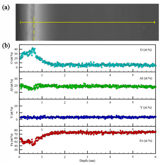
Figure 9.
SEM-EDS analysis of the oxide layer formed during fatigue testing at 800 °C on the surface of the flat dog-bone specimen: (a) SEM micrograph of the sample with line analysis (solid line). The dashed line indicates the edge of the sample. (b) Plot of the concentration profiles for O, Al, Y, and Fe.
4. Conclusions and Outlook
High temperature cyclic plastic testing of the recently developed new-generation ODS alloy at 800 °C was performed for the first time. The conclusions can be summarized as follows:
- The new-generation Fe–10Al–4Y2O3 ODS alloy was successfully prepared by rolling mechanically alloyed powders at 960 °C followed by annealing at 1200 °C/4 h.
- The microstructure of the new-generation ODS alloy consisted of large grains (129 μm) strengthened by the homogeneous dispersion of yttrium nano-precipitates (20 nm) with the volume fraction of 5%.
- The incremental fatigue step test performed at 800 °C (with a stepwise increase in the level of total strain amplitude from 0.1% to 0.6% with blocks of 100 cycles at each loading level) led to the acquisition of CSSC. The fatigue tests served as a preliminary check of the material performances at high temperature.
- After a comparison of the CSSCs of our experimental material with the results published in the literature, the newly developed ODS alloy reached similar or even better properties than conventional ODS steels, and the difference between our experimental material and In738LC is not crucial, because the new-generation ODS alloy has a rather high potential for applications at temperatures over 1000 °C.
- The detailed fractographic analysis revealed the laminated appearance of a fracture surface and the possible interaction of cyclic loading with the fast formation of a thin oxide film at newly created fracture surfaces during high temperature cyclic exposition.
The experiments performed in this paper confirmed a very effective testing methodology of high temperature fatigue properties. The comparison of the results of fatigue testing of the new-generation ODS alloy at 800 °C with the two types of ODS steels (ferritic and ferritic–martensitic) and fatigue resistant alloy In738LC indicates its promising fatigue properties at temperatures above 1000 °C, at which the alloy In738LC radically loses its mechanical properties due to rapid degradation of the strengthening γ’ phase. This motivates the authors to determine the high temperature fatigue properties of the new-generation ODS alloys in the temperature range of 1000–1200 °C in the near future.
Author Contributions
Conceptualization and methodology, A.C., I.Š., and J.S.; preparation of material and heat treatment, J.S.; fatigue testing, I.Š.; preparation of metallographic sections, I.Š.; evaluation of microstructure, A.C.; fractographic analysis, A.C.; scanning electron microscopy, A.C.; transmission electron microscopy, I.S.; hardness measurement, I.S.; writing—original draft preparation, A.C.; writing—review and editing, A.C., I.Š., and J.S. All authors have read and agreed to the published version of the manuscript.
Funding
This research was funded by the Czech Science Foundation in the framework of project 17-01641S.
Conflicts of Interest
The authors declare no conflict of interest. The funders had no role in the design of the study; in the collection, analyses, or interpretation of data; in the writing of the manuscript, or in the decision to publish the results.
References
- Klueh, R.L.; Shingledecker, J.P.; Swindeman, R.W.; Hoelzer, D.T. Oxide dispersion-strengthened steels: A comparison of some commercial and experimental alloys. J. Nucl. Mater. 2005, 341, 103–114. [Google Scholar] [CrossRef]
- Alamo, A.; Lambard, V.; Averty, X.; Mathon, M.H. Assessment of ODS-14%Cr ferritic alloy for high temperature applications. J. Nucl. Mater. 2004, 329, 333–337. [Google Scholar] [CrossRef]
- Husák, R.; Hadraba, H.; Chlup, Z.; Heczko, M.; Kruml, T.; Puchý, V. ODS EUROFER steel strengthened by Y-(Ce, Hf, La, Sc, and Zr) complex oxides. Metals 2019, 9, 1148. [Google Scholar] [CrossRef]
- Hadraba, H.; Chlup, Z.; Dlouhy, A.; Dobes, F.; Roupcova, P.; Vilemova, M.; Matejicek, J. Oxide dispersion strengthened CoCrFeNiMn high-entropy alloy. Mat. Sci. Eng. A 2017, 689, 252–256. [Google Scholar] [CrossRef]
- Svoboda, J.; Horník, V.; Stratil, L.; Hadraba, H.; Mašek, B.; Khalaj, O.; Jirková, H. Microstructure evolution in ODS alloys with a high-volume fraction of nano oxides. Metals 2018, 8, 1079. [Google Scholar] [CrossRef]
- Svoboda, J.; Ecker, W.; Razumovskiy, V.I.; Zickler, G.A.; Fischer, F.D. Kinetics of interaction of impurity interstitials with dislocations revisited. Prog. Mater. Sci. 2018, 101, 172–206. [Google Scholar] [CrossRef]
- Bártková, D.; Šmíd, M.; Mašek, B.; Svoboda, J.; Šiška, F. Kinetic study of static recrystallization in an Fe-Al-O ultra-fine-grained nanocomposite. Philos. Mag. Lett. 2017, 97, 379–385. [Google Scholar] [CrossRef]
- Kuběna, I.; Polák, J.; Plocinski, T.P.; Hébert, C.; Škorík, V.; Kruml, T. Microstructural stability of ODS steels in cyclic loading. Fatigue Fract. Eng. Mater. Struct. 2015, 38, 936–947. [Google Scholar] [CrossRef]
- Masek, B.; Khalaj, O.; Novy, Z.; Kubina, T.; Jirkova, H.; Svoboda, J.; Stadler, C. Behaviour of new ODS alloys under single and multiple deformation. Mater. Tehnol. 2016, 50, 891–898. [Google Scholar] [CrossRef]
- Raman, L.; Gothandapani, K.; Murty, B.S. Austenitic oxide dispersion strengthened steels: A review. Def. Sci. J. 2016, 66, 316–322. [Google Scholar] [CrossRef]
- Chlup, Z.; Fintová, S.; Hadraba, H.; Kuběna, I.; Vilémová, M.; Matějíček, J. Fatigue behaviour and crack initiation in CoCrFeNiMn high-entropy alloy processed by powder metallurgy. Metals 2019, 9, 1110. [Google Scholar] [CrossRef]
- Polák, J.; Obrtlík, K.; Hájek, M.; Vašek, A. Cyclic stress-strain response of polycrystalline copper in a wide-range of plastic strain amplitudes. Mat. Sci. Eng. A 1992, 151, 19–27. [Google Scholar] [CrossRef]
- Polák, J.; Hájek, M. Cyclic stress-strain curve evaluation using incremental step test procedure. Int. J. Fatigue 1991, 13, 216–222. [Google Scholar] [CrossRef]
- Šmíd, M.; Petrenec, M.; Polák, J.; Obrtlík, K.; Chlupová, A. Analysis of the effective and internal cyclic stress components in the inconel superalloy fatigued at elevated temperature. J. Adv. Mater. Res. 2011, 278, 393–398. [Google Scholar] [CrossRef]
- Petrenec, M.; Polák, J.; Tobiáš, J.; Šmíd, M.; Chlupová, A.; Petráš, R. Analysis of cyclic plastic response of nickel based In738LC superalloy. Int. J. Fatigue 2014, 65, 44–50. [Google Scholar] [CrossRef]
- Steckmeyer, A.; Rodrigo, V.H.; Gentzbittel, J.M.; Rabeau, V.; Fournier, B. Tensile anisotropy and creep properties of a Fe-14CrWTi ODS ferritic steel. J. Nucl. Mater. 2012, 426, 182–188. [Google Scholar] [CrossRef]
- Polák, J.; Petras, R.; Heczko, M.; Kruml, T.; Chai, G. Analysis of cyclic plastic response of heat resistant Sanicro 25 steel at ambient and elevated temperatures. Procedia Eng. 2014, 74, 68–73. [Google Scholar] [CrossRef]
- Šulák, I.; Obrtlík, K. Effect of tensile dwell on high-temperature low-cycle fatigue and fracture behaviour of cast superalloy MAR-M247. Eng. Fract. Mech. 2017, 185, 92–100. [Google Scholar] [CrossRef]
- Šulák, I.; Obrtlík, K.; Čelko, L.; Chráska, T.; Jech, D.; Gejdoš, P. Low cycle fatigue performance of Ni-based superalloy coated with complex thermal barrier coating. Mater. Charact. 2018, 139, 347–354. [Google Scholar] [CrossRef]
- Kubena, I.; Fournier, B.; Kruml, T. Effect of microstructure on low cycle fatigue properties of ODS steels. J. Nucl. Mater. 2012, 424, 101–108. [Google Scholar] [CrossRef]
- Soares, G.C.; Rodrigues, M.C.M.; Santos, L.D.A. Influence of Temperature on Mechanical Properties, Fracture Morphology and Strain Hardening Behavior of a 304 Stainless Steel. Mat. Res. 2017, 20, 141–151. [Google Scholar] [CrossRef]


© 2020 by the authors. Licensee MDPI, Basel, Switzerland. This article is an open access article distributed under the terms and conditions of the Creative Commons Attribution (CC BY) license (http://creativecommons.org/licenses/by/4.0/).