Abstract
High-pressure plunger-cylinder pairs in axial piston pumps are prone to brittle failure due to local contact stress, time-dependent material degradation, and cyclic loading, which complicates long-term reliability assessment. To address this issue, an integrated reliability analysis framework is proposed for SiC ceramic plunger pairs, combining local stress identification, strength degradation, and fatigue damage modeling. A three-dimensional finite element model identifies the critical contact region, where the maximum equivalent stress reaches 1291.5 MPa. An exponential strength degradation model and a time-variant stress-strength interference approach based on lognormal stress and Weibull strength distributions are adopted, with 105 Monte Carlo simulations used to evaluate failure probability. The results indicate that although the initial static reliability is close to 1.0, it decreases nonlinearly with service time, reaching 0.9663 at 10,000 h under moderate degradation. In addition, fatigue reliability is assessed by integrating the S-N curve of SiC with a cumulative damage model, enabling reliability-cycle curve construction and fatigue life prediction. The proposed method provides a quantitative framework for static, degradation-driven, and fatigue reliability assessment of high-pressure ceramic tribological structures.
1. Introduction
Hydraulic transmission is a form of power transmission that utilizes a liquid medium to transmit, convert, distribute, and control energy and signals. It is one of the key technologies in modern mechanical drive and control systems [1,2,3]. As the core power-generating and actuating component in hydraulic systems, the axial piston pump is widely and deeply applied in both industrial hydraulics and mobile hydraulics. In modern hydraulic technology, due to its excellent performance and broad applicability, it has become one of the most favored hydraulic components, gaining wide recognition and trust from the industry [4,5]. Characterized by high efficiency and high power-to-weight ratio [6], axial piston pumps are extensively used in construction machinery [7], marine engineering [8], military equipment, and other fields.
As a key friction pair in piston pumps, the plunger-cylinder assembly is considered critical for fluid sealing and torque transmission within the pump. Its tribological performance is widely regarded as a decisive factor influencing the overall service life of the pump [9,10]. Extensive numerical simulations and experimental investigations have been carried out by researchers both domestically and internationally. These studies have been conducted from various perspectives, including the geometric configuration between the plunger and the cylinder block [11], the selection of counterface materials [12], wear resistance evaluation [13], lubrication mechanisms [14], and oil film behavior [15]. Through these efforts, valuable insights have been obtained, providing continuous theoretical and experimental support for the advancement of high-speed and high-pressure piston pump technology [16]. To create a wellbore flow model, Zhao et al. [17] employed the volume of fluid method combined with computational fluid dynamics. They also simulated the gas-liquid flow characteristics between the plunger and the tubing gap during the plunger gas lift process, the plunger sealing mechanism is revealed, and the method of evaluating the efficacy of the plunger lifting fluid by the dimensionless coefficient is proposed, at the same time as the optimum plunger tubing diameter ratio and the optimum plunger diameter to length ratio of the plunger gas lift are given. A mathematical model was developed by Du et al. [18] to investigate the lubrication mechanism of the plunger-cylinder pair considering viscosity-temperature-pressure effects, enabling the pressure distribution and flow characteristics within the clearance to be analyzed. Surface texturing was introduced by Wang [19] to the sliding pair of a high-water-content hydraulic motor to improve tribological performance. It was demonstrated that cylindrical textures-with an area ratio of 0.12, depth-to-diameter ratio of 0.2, and spacing of 1 mm- enabled the pair to maintain excellent friction and wear characteristics under heavy-load and low-speed conditions. In addition, comparative studies were performed by Zhou et al. [20], where different ceramic materials (ZrO2, Al2O3, Si3N4, and SiC) were paired with 17-4PH steel in a seawater radial piston pump. It was concluded that ZrO2 was the most suitable material for micro-area contact friction pairs in such environments.
Reliability is defined as the ability of a product to perform its intended function under specified conditions for a designated period of time [21,22,23,24,25]. When reliability engineering is integrated with hydraulic systems, the concept of hydraulic reliability emerges as an important research direction. A hydraulic pump reliability model based on a triple mixed distribution-comprising Weibull, normal, and exponential distributions was established by S. Ruhi et al. using the Kolmogorov–Smirnov criterion. In this work, guidance was also provided on estimating the minimum maintenance cycle of hydraulic pumps through statistical modeling [26]. A small-sample reliability testing platform for hydraulic pumps was developed by Zhao et al. [27,28,29], in which volumetric efficiency was selected as the degradation characteristic based on principles of energy conservation and power recovery. Using this platform, the pump’s lifetime was predicted, the sampling interval for reliability tests was optimized, and a parallel multi-component energy-saving reliability testing method was proposed improving test efficiency while also promoting environmental sustainability. Additionally, a reliability design model for the slipper swashplate friction pair in axial piston pumps was constructed by Zhang et al., based on the matrix stochastic method derived from vector algebra theory. A new sensitivity-based approach for the reliability design of slippers and swashplates was thereby provided, offering a theoretical basis for structural optimization in axial piston pumps [30].
However, most existing studies on plunger pairs have focused on transient tribological behavior or local wear mechanisms, while the long-term structural reliability under combined effects of high contact stress, cyclic loading, and material degradation has received limited attention. In particular, silicon carbide (SiC) ceramics, which are widely used in plunger pairs due to their high hardness and excellent wear resistance, exhibit brittle fracture behavior and time-dependent strength degradation, which are not adequately captured by conventional reliability models based on static strength or normal distribution assumptions.
To address these limitations, this study proposes a degradation-aware reliability analysis method for ceramic plunger pairs by integrating finite element stress analysis, strength degradation modeling, and non-normal stress-strength interference theory. The proposed framework enables the evaluation of reliability evolution by accounting for local stress concentration, material degradation, and parameter uncertainty.
The main contributions of this work include:
- (1)
- identifying critical stress concentration regions in plunger pairs using finite element analysis;
- (2)
- introducing an exponential strength degradation model to establish a time-dependent reliability prediction framework;
- (3)
- employing non-normal statistical distributions and Monte Carlo simulation to quantify failure probability under uncertainty.
2. Principle and Methodology
2.1. Kinematic Analysis of the Plunger and Cylinder Block
As one of the key tribological pairs in axial piston pumps, the plunger pair plays a vital role in determining the pump’s mechanical efficiency, volumetric efficiency, and service life. The operating principle of the plunger is illustrated in Figure 1. During pump operation, the plunger rotates with the cylinder block along a circular path in the horizontal plane, while simultaneously executing reciprocating motion within the cylinder bore. This compound motion causes any point on the plunger axis to trace an elliptical trajectory, combining both rotational and axial displacements.
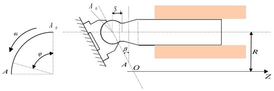
Figure 1.
Kinematic analysis of the plunger pair.
Taking the top dead center position , the plunger’s maximum protrusion within the bore, as the reference point, when the cylinder block rotates to an angle , the spherical head of the plunger moves from point A to point B. The corresponding axial displacement s of the plunger can be expressed as:
Substituting into the equation and simplifying:
where:
is the axial displacement of the plunger within the bore,
is the swash plate angle,
r is the distribution circle radius of the plunger,
is the angular rotation of the cylinder block.
When , the plunger moves from the position of maximum chamber volume to the minimum volume position, from the maximum extension to the minimum retraction. The difference between these two positions defines the maximum stroke of the plunger during the suction and discharge cycle.
By differentiating the above expression with respect to time, the reciprocating velocity v of the plunger relative to the cylinder bore can be obtained:
By further differentiating the above expression with respect to time, the axial acceleration of the plunger along the cylinder block can be calculated as:
2.2. Structural Configuration and Working Load Analysis of the Plunger
As shown in Figure 2, the interaction forces between the plunger and the cylinder block are complex; in this study, only the primary forces acting on the plunger are analyzed and calculated. These include: the axial hydraulic force , the axial inertial force and centrifugal inertial force during plunger motion; the swash plate reaction force N; two contact reaction forces between the plunger and the cylinder bore, , and the friction force . Other forces, due to their relatively small magnitudes and negligible influence on the plungers motion, are omitted for simplification. The following sections will analyze these major forces in detail, serving as a theoretical foundation for subsequent simulation calculations.
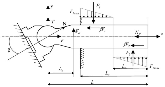
Figure 2.
Force analysis of the plunger pair.
- (1)
- Axial hydraulic force
d is the diameter of the plunger,
is the discharge pressure of the hydraulic pump.
- (2)
- Axial inertial force and centrifugal inertial force
- (3)
- Swash Plate Reaction Force
The reaction force N exerted by the swash plate on the plunger can be decomposed into two components: the axial force F along the plunger axis and he radial force T perpendicular to the plunger axis.
These components are given by:
where is the swash plate angle.
The axial force F is balanced by other axial forces such as the hydraulic force and the inertial force. However, the radial component T lacks a counterbalancing force, which may lead to bending moments on the main shaft and eccentric deformation of the plunger. Eventually, combined with the centrifugal force , this causes contact stress between the plunger and the cylinder bore wall.
- (4)
- Contact reaction forces between the plunger and cylinder bore: and
Due to the extremely small clearance between the plunger and the bore, and the significant difference in local contact stiffness, the detailed distribution of the two-point contact forces can be neglected. The combined effect of the radial force T and centrifugal force can be approximated as a continuous, uniformly distributed linear contact stress along the bore wall.
Based on geometric similarity and the principle of similar triangles, the distribution model for the contact reaction force can be derived.
- (5)
- Friction force between the cylinder block and plunger
The friction force between the cylinder block and the plunger is given by:
where is the coefficient of friction, which depends on the material pairing between the plunger and the cylinder block.
2.3. Stress-Strength Interference Model
The stress-strength interference model is a probabilistic approach widely used in structural reliability analysis, particularly for evaluating the failure probability of mechanical components under random loading conditions [31,32,33]. The fundamental concept of this model is that failure occurs when the applied stress exceeds the material strength. In mechanical design, both the material strength S of a component and the working stress σ it experiences are treated as random variables with inherent statistical distributions.
The stress variable represents the equivalent stress generated by operational loads acting on the component, while the strength variable reflects the material’s or structure’s capacity to resist the applied load. Failure is considered to occur when ; otherwise, the system is assumed to remain in a safe state.
Both the stress and the strength are treated as statistically distributed random variables and are typically assumed to be mutually independent. When both stress and strength follow normal distributions, the probability density function of stress can be expressed as
where and denote the mean value and standard deviation of stress, respectively.
Similarly, the probability density function of strength is given by
where and are the mean value and standard deviation of material strength.
Let the limit-state variable be defined as
which represents the difference between strength and stress. According to statistical theory, the variable also follows a normal distribution with the following parameters:
Then, the structural reliability R, defined as the probability that y, is calculated by:
This can be simplified using the cumulative distribution function of the standard normal distribution:
3. Structural Reliability Evaluation of the Plunger Pair
3.1. Finite Element Analysis Procedure
The geometric model of the plunger pump primarily includes the three-dimensional dimensions of its key components, along with associated physical properties such as material, mass, and center of gravity. These physical parameters serve as the foundation for constructing the physical model. To accelerate the abstraction of the geometric model into a physical model during analysis and to reduce computational memory consumption, simplifications are made for non-deterministic features in the modeling process.
Therefore, auxiliary components such as bolts and fasteners are omitted at this stage. The plunger pump is assumed to operate under steady-state lubricated conditions, under which a stable oil film is maintained between the friction pairs. The effects of surface roughness and lubrication on the macroscopic contact behavior are implicitly represented through an equivalent constant friction coefficient. The physical properties of the hydraulic oil are taken from the typical room-temperature range of mineral-based hydraulic oils, with a density of approximately 850 kg/m3 and a dynamic viscosity of about 0.03–0.05 Pa·s, to characterize the operating conditions. The frictional contact between the plunger outer surface and the cylinder bore is modeled using a constant friction coefficient of 0.16 [34]. Only the cylinder block and the plunger are included in the finite element model, and the corresponding finite element configuration is shown in Figure 3.
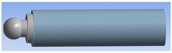
Figure 3.
Structural schematic of the plunger pair.
The main parameters of the plunger pump are listed in Table 1. The basic geometric parameters of the plunger friction pair are shown in Table 2. The plunger is made of SiC ceramic, and the cylinder block is modeled as 304 stainless steel, a commonly used engineering structural material [35]. In the plunger-cylinder block system, the cylinder block primarily serves load-bearing and constraining functions, whereas the tribological behavior and reliability response of the system are mainly governed by the SiC ceramic plunger. In addition, 304 stainless steel exhibits good corrosion resistance, mechanical stability, and manufacturability, and it can maintain structural integrity and dimensional stability under high water-based hydraulic media, making it suitable as a structural material for the cylinder block.

Table 1.
Main Parameters of the Plunger Pump.
Table 2.
Geometric Parameters of the Plunger Pair in the Plunger Pump.
The material properties adopted for the plunger and cylinder block in the numerical model are summarized in Table 3, where the mechanical parameters of hot-pressed sintered SiC ceramics and 304 steel were primarily sourced from relevant literature [36]. To verify the basic mechanical properties of the SiC material, a static tensile test was performed on the specimen, with the experimental setup illustrated in Figure 4. The experimental results show that the SiC specimen exhibits an average tensile strength of approximately 350 MPa. However, considering that the plunger is predominantly subjected to high compressive contact stresses during operation, the compressive strength (2000 MPa) is adopted as the failure threshold for the subsequent reliability analysis.
Table 3.
Material Properties of the Plunger and Cylinder Block [36].
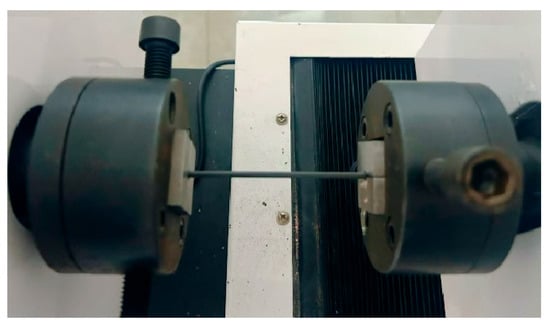
Figure 4.
Tensile test setup for verifying SiC material quality.
The detailed analysis steps are given as follows:
- (1)
- Assign material properties and contact types to each part of the model;
- (2)
- Generate an appropriate mesh for the geometry;
- (3)
- Apply boundary conditions and loading;
- (4)
- Solve the model;
- (5)
- Post-process and analyze the results.
The plunger pair model is divided into two parts: the plunger and the cylinder block. The finite element model is established using ANSYS Workbench 2024 R1, in which the geometry, material properties, boundary conditions, and contact interactions are defined. To ensure the reliability of the numerical results, a mesh convergence study is conducted by monitoring the maximum von Mises stress at the critical plunger-bore contact region under different mesh sizes. The results as shown in Figure 5 indicate that further mesh refinement leads to progressively smaller changes in the stress magnitude. When the mesh size is reduced from 0.5 mm to 0.4 mm, the variation in the maximum stress becomes negligible, indicating that mesh convergence has been achieved. Therefore, a mesh size of 0.5 mm is selected for the subsequent finite element analyses, considering both computational accuracy and efficiency.
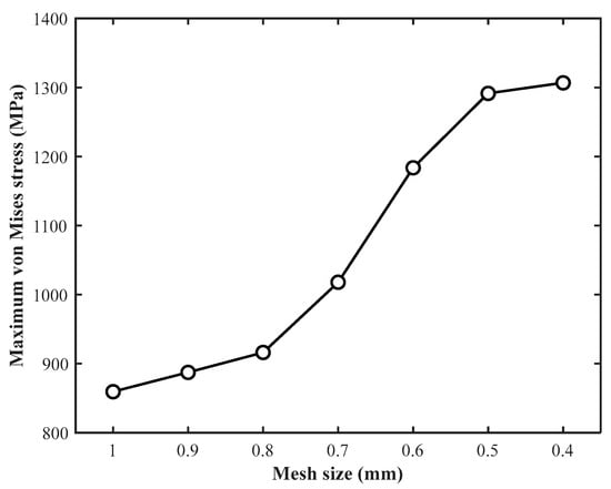
Figure 5.
Mesh convergence analysis of the plunger structure.
The meshing result is shown in Figure 6, with a total of 561,996 nodes and 202, 692 elements.
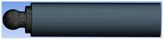
Figure 6.
Meshing result of the plunger pair model.
After meshing, appropriate constraints and loading conditions were applied to the model. Specifically, a fixed constraint was applied to the outer wall of the cylinder block to limit its rigid body displacement. To accurately simulate the fluid–structure interaction and realistic contact mechanics under the rated discharge condition, a distributed hydraulic pressure of 31.5 MPa was directly applied to the plunger end face to provide the actual axial driving force. Simultaneously, considering the radial expansion effect of the cylinder block under high pressure, the same hydraulic pressure was applied to the inner wall of the plunger chamber, thereby effectively capturing its influence on the clearance variation and contact stress distribution. In addition, to simulate the mechanical limiting effect of the swash plate, an axial displacement constraint was applied to the plunger spherical head. Furthermore, to reproduce the eccentric wear effect caused by the swash plate inclination, a lateral load of approximately 2150 N was applied to the plunger head based on the force decomposition principle. This loading strategy realistically reflects the load transmission path within the high-pressure piston pump and effectively captures the bending stress characteristics at the plunger neck as well as the contact stress distribution at the cylinder bore entrance. Finally, the stress distribution results of the model were calculated and analyzed.
The equivalent stress distribution of the plunger is presented in Figure 7. The results show that the maximum equivalent stress occurs at the contact edge between the plunger head and the cylinder bore, reaching a peak of 1291.5 MPa. Since this value remains within the compressive strength limit of SiC ceramic (2000 MPa), crushing failure at the contact interface is unlikely. However, it is worth noting that a significant stress concentration region was observed at the plunger neck. The stress elevation in this region is primarily attributed to the bending moment induced by the lateral load. Given the inherent low tensile strength of ceramic materials, this indicates that neck fracture represents a more critical potential failure risk than contact crushing.
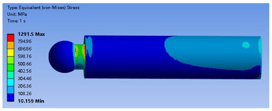
Figure 7.
Stress contour of the plunger.
The equivalent stress distribution of the cylinder block under plunger loading conditions is shown in Figure 8. The results indicate that the maximum equivalent stress is concentrated on the inner wall of the cylinder bore within the contact region, reaching a peak of 721.03 MPa. Although this value significantly exceeds the yield strength of 304 stainless steel, the high-stress region is strictly confined to the sharp contact edge on the inner wall, attributed to stress singularity. From a physical perspective, this confirms that localized plastic deformation occurs on the bore surface, explaining the wear mechanism observed in service. However, the stress level in the bulk material remains within the elastic regime, ensuring the overall structural integrity.
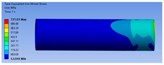
Figure 8.
Stress contour of the cylinder block.
The equivalent stress distribution of the plunger under assembly and contact conditions inside the cylinder bore is presented in Figure 9. In the finite element model, both the plunger and the cylinder block are included, and the contact interaction between the outer surface of the plunger and the inner wall of the cylinder bore is taken into account. Therefore, the stress field shown in the figure represents the stress state of the plunger under actual assembly constraints.
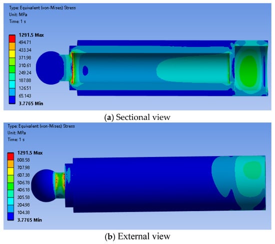
Figure 9.
Equivalent stress contours of the plunger inside the cylinder bore.
3.2. Reliability Evaluation of the Plunger Structure
To evaluate the reliability of the plunger structure under typical loading conditions in terms of strength margin and failure probability, a stress-strength interference model is introduced in this study. This model is widely applied in the reliability analysis of crack-free structures under static loading, as it provides a probabilistic safety margin for structural capacity against design loads.
Based on the finite element simulation results, the maximum equivalent stress of the plunger structure is calculated as
Considering uncertainties from manufacturing tolerance, loading fluctuations, and environmental variability, a standard deviation of 10% is adopted:
The compressive strength of the SiC material is:
Considering internal defects in ceramic materials and batch variability, the standard deviation of strength is also taken as 10%:
The reliability index Z of the plunger structure is then computed as:
Therefore, the structural reliability is:
This indicates that the structural reliability under static loading is extremely high, with the failure probability approaching zero. Under the current design conditions and the use of SiC material, the plunger pair exhibits a strength redundancy far exceeding the applied load requirements. Even when considering ±10% fluctuations in both stress and strength, no overlap between stress and strength distributions is observed. This result is consistent with experimental observations and confirms the feasibility of employing SiC ceramic as the frictional material in high-pressure plunger pairs.
3.3. Reliability Analysis of the Plunger Considering Strength Degradation
During long-term service, the strength of hydraulic plunger pair structures gradually deteriorates due to damage mechanisms such as frictional wear, microcrack propagation, and surface fatigue under cyclic contact loading [37,38]. Under practical operating conditions, the working-fluid temperature and friction-induced local heating may further accelerate these damage evolution processes. The degradation is particularly critical for ceramic materials such as silicon carbide (SiC), which are widely used in plunger pairs due to their high initial strength and excellent wear resistance. However, the inherent brittleness of ceramics makes them highly sensitive to defect evolution, where microscopic flaws may progressively develop into macroscopic fracture sources during operation. Traditional static reliability assessments based solely on initial material strength therefore fail to capture the actual failure risk over the service life.
To address this limitation, a time-dependent strength degradation model is introduced in this study, and a dynamic reliability evaluation framework is established for the plunger pair. By incorporating a time-evolving stress-strength interference model, the long-term effect of strength degradation on structural reliability is quantitatively assessed. It should be noted that the temperature effects are considered as operating factors influencing the degradation process rather than being explicitly coupled into the simulation [31,37].
Based on the failure mechanisms of ceramic materials under thermal, mechanical, and tribological conditions, an exponential degradation model is adopted to describe the evolution of material strength with service time [39]:
In this model, represents the initial material strength, denotes the degradation rate (unit: 1/h), and is the service time in hours. The model is derived from a first-order differential equation and captures the physical phenomenon whereby the degradation rate increases as the remaining strength decreases. It has been widely applied in the lifetime assessment of ceramic components, composite materials, and high-temperature structural elements. The degradation rate λ is not treated as an experimentally measured intrinsic material constant. Instead, it is introduced as a representative model parameter to reflect different degradation severity levels associated with various service environments [40]. Previous studies have demonstrated that the damage evolution and strength degradation behavior of brittle materials can vary significantly depending on operating conditions such as load fluctuation, lubrication state, and environmental stability [41].
To better capture this variability, three representative degradation rate levels are defined for SiC materials in this study, corresponding to slow, moderate, and fast degradation scenarios, as summarized in Table 4. These degradation rates are adopted for scenario-based analysis to investigate the influence of degradation severity on the reliability evolution of the plunger pair, rather than to represent unique material constants.
Table 4.
Representative degradation rate of SiC material under different service environments.
Stress-strength interference-based failure criterion is adopted, and failure is defined to occur when the local equivalent stress at the critical initial plunger-bore contact region exceeds the degraded effective material strength. An initial strength of with a standard deviation of is assumed, consistent with typical mechanical properties of SiC ceramic materials. The stress input used in the reliability assessment is taken from the finite element results at the critical location, the initial plunger-bore contact region where local stress concentration occurs. The residual strength S(t) is updated with service time according to the adopted strength degradation model, and the degraded strength is incorporated into the stress-strength interference function. Accordingly, the reliability at each time point is evaluated analytically as . The evaluation is conducted over a service period of t ∈ [0, 10,000] h and the resulting reliability evolution is summarized in Table 5. Based on the reliability evaluation results summarized in Table 5, noticeable differences can be observed among the degradation models in terms of both the magnitude and trend of reliability decay. To further illustrate the time-dependent evolution of reliability and to enable a direct comparison of long-term behaviors under different degradation scenarios, the corresponding reliability curves are plotted in Figure 10.
Table 5.
Reliability R(t) under Different Degradation Scenarios.
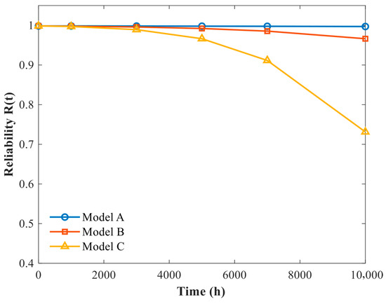
Figure 10.
Reliability evolution under different degradation scenarios.
As seen in Table 5, during the early stage of service (0–3000 h), the plunger pair structure maintains a high level of reliability approaching 100% regardless of the strength degradation rate. This indicates a sufficient initial safety margin in the design. However, as service time increases, the reliability begins to decline significantly, particularly under high degradation rate conditions. By 10,000 h, the reliability drops to 0.7313, revealing a non-negligible risk of long-term structural failure. Overall, under constant high-stress conditions, the dominant failure mechanism shifts from load-induced effects to performance degradation driven by time-dependent strength reduction. This highlights the critical necessity of incorporating degradation behavior into the reliability assessment of ceramic structural components.
3.4. Influence of Different Distribution Models on the Reliability Evaluation
In the classical stress-strength interference model, both stress and strength are typically assumed to follow normal distributions. However, this assumption may become invalid in cases where material strength exhibits strong skewness, local stress concentration is severe, or failure risk is sensitive to distribution tails. Such simplification may result in reliability predictions that deviate from actual structural performance. To systematically evaluate the static reliability of the plunger pair structure, two sets of probabilistic models are compared in this study, with input parameter variability taken into account:
Model 1 (Standard Model): Both stress and strength follow normal distributions.
Model 2 (Non-normal Model): Stress follows a lognormal distribution, and strength follows a Weibull distribution.
The probability density functions (PDF) of stress and strength under both distribution assumptions are illustrated in Figure 11.
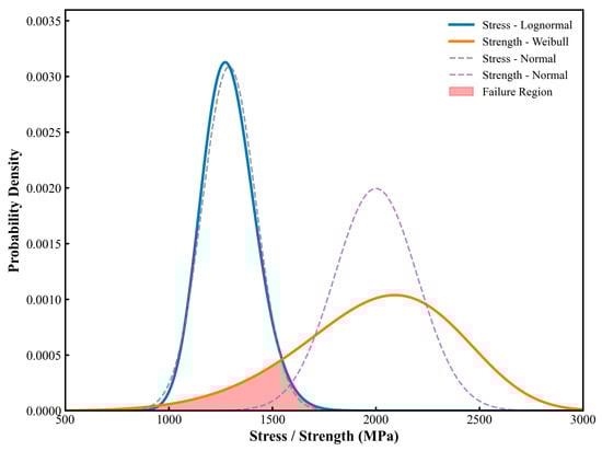
Figure 11.
Comparison of stress and strength distributions under different distribution models.
Both distribution models were configured with the same input parameters: a stress mean of 1291.5 MPa and standard deviation of 129.15 MPa, and a strength mean of 2000 MPa with a standard deviation of approximately 200 MPa. Monte Carlo simulations were conducted with 105 samples for each case to evaluate the probability of failure. The results are summarized in Table 6.
Table 6.
Reliability and Failure Probability under Different Distribution Models.
The analysis shows that under the traditional normal distribution model, the predicted structural reliability is 100%, with no failure samples observed. In contrast, under the lognormal-Weibull model, the failure rate increases to 5.18%, indicating that approximately 518 out of every 10,000 units may fail due to extreme stress amplification combined with brittle degradation. From the perspective of distribution characteristics, the lognormal distribution better captures the right-skewed tail behavior of stress, which is often caused by local concentration effects such as installation misalignment or eccentric wear in plunger pairs. Meanwhile, the Weibull distribution, widely adopted for modeling ceramic material strength, is suitable for representing the statistical behavior of failure driven by microcrack mechanisms and is particularly effective in capturing the contribution of material weak points in brittle fracture.
In summary, although the structure exhibits a high safety margin, the failure probability, albeit small, remains sensitive to tail behaviors. Employing more realistic non-normal distribution models enables effective capture of reliability fluctuations under extreme scenarios, offering valuable guidance for the design of safety-critical systems.
3.5. Fatigue Reliability Calculation of the Plunger
Based on the analysis of the plunger motion state, the equivalent stress distribution on the plunger surface is obtained, as shown in Figure 12. The surface damage morphology of a real plunger component after long-term operation is presented in Figure 13. It can be observed that noticeable wear and damage traces appear in localized regions on the plunger surface, and their locations show a certain qualitative correspondence with the regions of high equivalent stress predicted by the finite element analysis. This observation indicates, to some extent, that the numerical model established based on stress analysis exhibits engineering rationality in identifying potential damage-prone regions of the plunger pair.
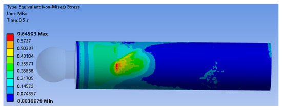
Figure 12.
Equivalent stress contour of the plunger surface under operating conditions.
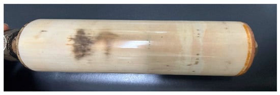
Figure 13.
Surface damage morphology of a plunger after long-term service operation.
The fatigue failure of mechanical structures results from the progressive accumulation of damage as the number of load cycles increases. The fatigue failure process is modeled using the S-N curve and a cumulative fatigue-damage model.
The stress-life (S-N) relationship of the SiC material under cyclic loading is presented in Figure 14 [42]. The results are shown as discrete data points corresponding to selected stress levels, rather than as continuous curves. This representation is commonly adopted in ceramic fatigue studies, where fatigue life is evaluated at specific stress amplitudes and significant scatter is typically observed. The figure is intended to illustrate the stress-life trend and relative fatigue performance, rather than to provide a continuous fitted S-N curve.
where , and C and m are material constants. When , the critical damage occurs.
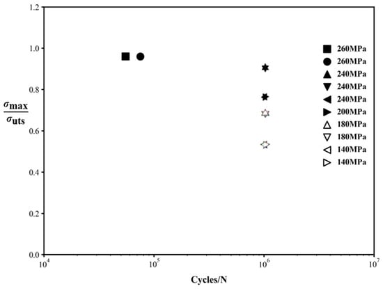
Figure 14.
The fatigue life S-N curve of unidirectional SiC.
For most materials, the fatigue life generally follows a lognormal distribution. The probability density function is [43]
The probability density function of the cumulative damage is
Therefore, the cumulative damage D and the fatigue life share similar probability distributions, and the log-standard deviation of D is
Under constant-amplitude loading, the log-standard deviation of the cycle count n satisfies [44]
Accordingly, the log-standard deviation of the damage D is
For multiple loading blocks, the total log-standard deviation of the accumulated damage becomes
When the mechanical structure fails, the critical damage is assumed to follow a lognormal distribution, i.e.,
If the expected value of the critical damage is , then
Define the performance (limit-state) function of cumulative damage as
Hence, the reliability as a function of the number of cycles is
where is the fatigue life obtained from the S-N curve for the -th loading block. If the service environment is more complex, other life-prediction models may be used to obtain .
When test data are scarce and the exponents are difficult to identify, one may set , so that the cumulative damage model reduces to Miner’s rule, and the reliability expression simplifies to [45]
Based on the obtained probability density function (PDF) of fatigue damage and its standard deviation, and given the plunger’s minimum cycle count and fatigue life, the fatigue reliability can be evaluated, as shown in Figure 15.
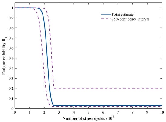
Figure 15.
Fatigue reliability curve of the plunger.
4. Conclusions
- (1)
- Focusing on the reliability issues of ceramic plungers in plunger pairs, this study proposes a comprehensive reliability analysis framework that integrates finite element analysis, strength degradation modeling, and stress-strength interference theory. A three-dimensional finite element model is established to investigate the local contact behavior between the plunger and the cylinder bore, identifying the plunger head and the cylinder bore inlet as critical stress concentration regions. The numerical results indicate that the maximum equivalent stress in this region reaches approximately 716.12 MPa, which plays a dominant role in governing the structural safety and failure risk of the plunger pair and provides a clear mechanical basis for subsequent reliability and life assessment.
- (2)
- An exponential strength degradation model is further introduced to incorporate the time-dependent evolution of material properties into the stress-strength interference framework, enabling quantitative evaluation of the long-term reliability of the plunger pair. The results show that although the plunger exhibits a relatively high static safety margin at the initial stage, its reliability decreases nonlinearly with service time under material degradation, and the long-term failure risk is primarily governed by degradation behavior. By adopting a lognormal stress distribution and a Weibull strength distribution in combination with Monte Carlo simulation, the proposed method effectively captures tail failure risks induced by local stress concentration and brittle fracture, overcoming the limitations associated with conventional normal distribution assumptions. Moreover, by incorporating the S-N curve of SiC and a cumulative damage model, a fatigue reliability assessment approach for plunger pairs under cyclic loading conditions is established, providing a new modeling perspective for lifetime prediction and safety evaluation of ceramic tribological structures.
- (3)
- This study primarily focuses on reliability modeling methods and degradation evolution mechanisms for ceramic plungers. While the exponential strength degradation model and the assumption of a constant degradation rate offer modeling simplicity, they present certain limitations in fully describing the condition-dependent damage mechanisms and brittle fracture behavior of SiC ceramics under complex service conditions. In addition, thermos-fluid-solid multi-field coupling effects and their influence on local stress and degradation behavior are not explicitly considered in this work. These issues will be further addressed in future studies through component-level experimental investigations and multi-field coupled modeling, with the aim of improving the predictive accuracy and engineering applicability of the proposed framework.
Author Contributions
Conceptualization, Y.L.; Methodology, Z.W.; Software, Y.C.; Writing—original draft, L.Y.; Writing—review & editing, X.L.; Funding acquisition, Y.L. All authors have read and agreed to the published version of the manuscript.
Funding
This research received no external funding.
Data Availability Statement
The data used in this study are included in the manuscript.
Acknowledgments
This work is supported by the Beijing Tianma Intelligent Control Technology Co., Ltd.
Conflicts of Interest
Author Yao Cui was employed by Beijing Tianma Intelligent Control Technology Co., Ltd. The remaining authors declare that the research was conducted in the absence of any commercial or financial relationships that could be construed as a potential conflict of interest.
Nomenclature
| Symbol | Description |
| Axial displacement of the plunger inside the cylinder bore | |
| Swash plate angle | |
| r | Radius of the plunger distribution circle |
| Rotation angle of the cylinder block | |
| v | Axial velocity of the plunger relative to the cylinder bore |
| a | Axial acceleration of the plunger |
| d | Plunger diameter |
| Pd | Discharge pressure |
| Axial hydraulic force acting on the plunger | |
| mz | Total mass of plunger and slipper |
| Axial inertial force of the plunger | |
| Centrifugal inertial force acting on the plunger | |
| N | Normal reaction force exerted by the swash plate on the plunger |
| F | Axial component of the swash plate reaction force |
| T | Radial component of swash plate reaction force |
| Contact reaction forces on both sides of the plunger–bore interface | |
| Friction coefficient between the plunger and the cylinder bore | |
| Friction force at the plunger-bore contact interface | |
| L | Plunger length |
| D | Diameter of the plunger distribution circle |
| δ | Radial clearance between the plunger and the cylinder bore |
| n | Rotational speed of the cylinder block |
| S | Random variable representing material strength |
| Mean value of stress | |
| Standard deviation of stress | |
| Mean value of material strength | |
| Standard deviation of material strength | |
| Initial strength of the SiC material | |
| Strength degradation rate parameter | |
| Time-dependent degraded residual strength | |
| Time-dependent reliability | |
| Fatigue life | |
| Stress amplitude | |
| D | Accumulated fatigue damage |
| Critical fatigue damage | |
| Number of load cycles in the -th loading block | |
| Fatigue life corresponding to the -th loading block | |
| Fatigue limit-state function |
References
- Mahankar, P.S.; Dhoble, A.S. Review of hydraulic seal failures due to effect of medium to high temperature. Eng. Fail. Anal. 2021, 127, 105552. [Google Scholar] [CrossRef]
- Jiang, J.; Wu, Z.; Pan, S.; Meng, X.; Liu, D.; Mu, K.; Cai, C. High-performance liquid metal-based SiC/Graphene-Mo hybrid nanofluid for hydraulic transmission. Tribol. Int. 2024, 198, 109871. [Google Scholar] [CrossRef]
- Kan, Y.; Sun, D.; Luo, Y.; Ma, K.; Shi, J. Optimal design of power matching for wheel loader based on power reflux hydraulic transmission system. Mech. Mach. Theory 2019, 137, 67–82. [Google Scholar] [CrossRef]
- Ye, S.; Zheng, C.; Bao, Y.; Miao, K.; Liu, H.; Zhao, S. Dynamic characteristics analyses of coupled-multibody axial piston Pump model. Int. J. Mech. Sci. 2025, 299, 110379. [Google Scholar] [CrossRef]
- Xia, S.; Huang, C.; Ye, S.; Jiao, W.; Xia, Y.; Zhu, Z. Study on the running-in tribological performance and mechanism of the valve plate with surface texture for axial piston pumps. Wear 2025, 574–575, 206085. [Google Scholar] [CrossRef]
- Chao, Q.; Zhang, J.; Xu, B.; Wang, Q.; Huang, H. Test rigs and experimental studies of the slipper bearing in axial piston pumps: A review. Measurement 2019, 132, 135–149. [Google Scholar] [CrossRef]
- Deshmukh, S.; Raina, A.K.; Murthy, V.M.S.R.; Trivedi, R.; Vajre, R. Roadheader-A comprehensive review. Tunnellingand Undergr. Space Technol. 2020, 95, 103–148. [Google Scholar] [CrossRef]
- Rhakasywi, D.; Marasabessy, A.; Hatuwe, M.R.; Kotahatuhaha, S. Safety factor of pump vibrations on ships based on the natural frequency of pump vibrations according to ISO 10816-3. Safety 2020, 43, 180–192. [Google Scholar]
- Dong, J.; Deng, Y.; Cao, W.; Wang, Z.; Ma, W.; Wu, D.; Ji, H.; Liu, Y. Wear failure analysis of suction valve for high pressure and large flow water hydraulic plunger pump. Eng. Fail. Anal. 2022, 134, 106095. [Google Scholar] [CrossRef]
- Wang, Y.; Su, H.; Qian, N.; Liu, K.; Dai, J.; Zhao, Z.; Ding, W. Neck-spinning quality analysis and optimization of process parameters for plunger components: Simulation and experimental study. Chin. J. Aeronaut. 2021, 34, 174–191. [Google Scholar] [CrossRef]
- Haidak, G.; Kou, J.; Wei, X.; Kengne, E.; Wang, D. Numerical investigation on suitable micro-groove structure for improved efficiency between piston and cylinder in axial piston machine. Mech. Based Des. Struct. Mach. 2025, 1–28. [Google Scholar] [CrossRef]
- Liang, Y.; Wang, W.; Zhang, Z.; Xing, H.; Wang, C.; Zhang, Z.; Gao, D. Effect of material selection and surface texture on tribological properties of key friction pairs in water hydraulic axial piston pumps: A review. Lubricants 2023, 11, 324. [Google Scholar] [CrossRef]
- Ünlü, B.S.; Atik, E.; Meriç, C. Effect of loading capacity (pressure-velocity) to tribological properties of CuSn10 bearings. Mater. Des. 2007, 28, 2160–2165. [Google Scholar] [CrossRef]
- Du, Y.Y.; Cao, Q.X.; Wang, W.S.; Li, N.N.; Liu, X.Q. Lubrication and Leakage Characteristics of Piston Pair in Plunger Pump Considering Elastic Deformation. Mach. Tool Hydraul. 2023, 51, 144–149. [Google Scholar] [CrossRef]
- Ye, S.; Lai, W.; Hou, L.; Bu, X. Modeling and Experimental Validation of Lubrication Characteristics of Spherical Valve-plate Pairs with Conical Cylinder Block. China Mech. Eng. 2022, 33, 2420–2428. [Google Scholar] [CrossRef]
- Zhang, C.; Zhu, C.; Meng, B.; Li, S. Challenges and solutions for high-speed aviation piston pumps: A review. Aerospace 2021, 8, 392. [Google Scholar] [CrossRef]
- Zhao, K.; Mu, L.; Tian, W.; Bai, B. Gas-liquid flow seal in the smooth annulus during plunger lifting process in gas wells. J. Nat. Gas Sci. Eng. 2021, 95, 104195. [Google Scholar] [CrossRef]
- Du, Y.; Zhao, H.; Ji, H.; Wang, W.; Wang, H.; Xu, F. Research on lubrication mechanism of plunger pair considering viscosity temperature and pressure effect. Phys. Fluids 2024, 36, 097119. [Google Scholar] [CrossRef]
- Wang, B. Study on the Effect of Surface Texture on Tribological Performance of High Water-Based Hydraulic Motor Slipper Pairs; China University of Mining and Technolog: Xuzhou, China, 2017. [Google Scholar]
- Zhou, J.; Wu, J.; Yi, M.; Yu, G. Tribological Property for Ceramics Friction Pair of Seawater Radial Piston Pump. Chin. Hydraul. Pneum. 2017, 10, 23–26. [Google Scholar] [CrossRef]
- Cheng, T.; Fan, D.; Liu, X.; Wang, J. Reliability analysis for manufacturing system of drive shaft based on dynamic Bayesian network. Qual. Reliab. Eng. Int. 2024, 40, 4482–4497. [Google Scholar] [CrossRef]
- Huang, Y.; Zhang, J.; Wang, B.; Wei, Y. An adaptive Kriging method focusing on reliability-sensitive space-time for time-variant reliability analysis. Eksploat. I Niezawodn.-Maint. Reliab. 2025, 27, 203980. [Google Scholar] [CrossRef]
- Li, Y.; Zhang, X.; Ran, Y.; Zhang, G. Reliability modeling and analysis for CNC machine tool based on meta-action. Qual. Reliab. Eng. Int. 2021, 37, 1451–1467. [Google Scholar] [CrossRef]
- Jong, C.H.; Kye, J.H.; Li, G.S.; Kim, G.H. A non-probabilistic reliability-based topology optimization of continuum structures using evolutionary topology optimization method. J. Braz. Soc. Mech. Sci. Eng. 2025, 47, 485. [Google Scholar] [CrossRef]
- You, D.; Liu, S.; Li, F.; Liu, H.; Zhang, Y. Reliability Assessment Method Based on Small Sample Accelerated Life Test Data. Eksploat. I Niezawodn.-Maint. Reliab. 2025, 27, 192170. [Google Scholar] [CrossRef]
- Ruhi, S.; Karim, M.R. Selecting statistical model and optimum maintenance policy: A case study of hydraulic pump. Springer Plus 2016, 5, 969. [Google Scholar] [CrossRef]
- Guo, R.; Chao, N.; Zhang, J.; Wang, P.; Sun, Y.; Zhang, J.; Li, J. Life prediction and test period optimization research based on small sample reliability test of hydraulic pumps. High Technol. Lett. 2017, 23, 63–70. [Google Scholar] [CrossRef]
- Wu, P.; Zhao, J.; Guo, R.; Zhu, M.; Wang, Q.M. Research on a Parallel Energy-saving Method of Reliability Test for Hydraulic Components. Metall. Equip. 2017, 9–13. [Google Scholar] [CrossRef]
- Zhang, C.; Zhao, J.; Rong, X. Energy-saving Research on Parallel Type Reliability Test Bench. Chin. Hydraul. Pneum. 2015, 39, 83–87. [Google Scholar] [CrossRef]
- Zhang, T.; Zhang, Y. A new model for reliability design and reliability sensitivity analysis of a hydraulic piston pump. Proc. Inst. Mech. Eng. Part O J. Risk Reliab. 2017, 231, 11–24. [Google Scholar] [CrossRef]
- Ye, K.; Wang, H.; Ma, X. A generalized dynamic stress-strength interference model under -failure criterion for self-healing protective structure. Reliab. Eng. Syst. Saf. 2023, 229, 108838. [Google Scholar] [CrossRef]
- Li, L.; Liu, M.; Shen, W.; Cheng, G. An expert knowledge-based dynamic maintenance task assignment model using discrete stress-strength interference theory. Knowl. Based Syst. 2017, 131, 135–148. [Google Scholar] [CrossRef]
- Shang, L.; Yan, Z. Reliability estimation stress-strength dependent model based on copula function using ranked set sampling. J. Radiat. Res. Appl. Sci. 2024, 17, 100811. [Google Scholar] [CrossRef]
- Kou, B.; Li, Z.; Li, S.; Hao, R. Dry Sliding Friction and Wear Performance of Slipper Pair of Axial Piston Pump at High Temperature. Lubr. Eng. 2021, 46, 115–121. [Google Scholar] [CrossRef]
- Kou, B.; Li, R.; Li, Z.; Hao, R. Study on Tribological Properties of Ceramic Friction Pair for High Water-based Hydraulic Valve. Lubr. Eng. 2023, 48, 86–91. [Google Scholar] [CrossRef]
- Li, R. Study on Friction Properties of Ceramic Materials for Friction Pair of Mining High Water-Based Axial Piston Pump. Master’s Thesis, Taiyuan University of Science and Technology, Taiyuan, China, 2023. [Google Scholar] [CrossRef]
- Yu, Y.; Wang, L.; Wu, J.; Chang, S.; Zhang, X. An enhanced nonlinear fatigue cumulative damage model based on toughness exhaustion and strength degradation. Int. J. Fatigue 2025, 198, 109025. [Google Scholar] [CrossRef]
- Xiao, Q.; Wang, X.; Chen, D.; Zhou, X.; Liu, X.; Yang, W. A new nonlinear fatigue cumulative damage model based on load interaction and strength degradation. Int. J. Fatigue 2025, 191, 108709. [Google Scholar] [CrossRef]
- Guo, R.; Zhou, J.; Zhang, C.; Zhao, J.; Zhang, Y. Reliability evaluation of axial piston pump based on degradation failure. In Proceedings of the 2017 International Conference on Sensing, Diagnostics, Prognostics, and Control (SDPC), Shanghai, China, 16–18 August 2017; IEEE: Piscataway, NJ, USA, 2017; pp. 204–209. [Google Scholar] [CrossRef]
- Chang, M.; Huang, X.; Coolen, F.; Coolen-Maturi, T. Reliability analysis for systems based on degradation rates and hard failure thresholds changing with degradation levels. Reliab. Eng. Syst. Saf. 2021, 216, 108007. [Google Scholar] [CrossRef]
- Lawn, B.R.; Huang, H.; Lu, M.; Borrero-López, Ó.; Zhang, Y. Threshold damage mechanisms in brittle solids and their impact on advanced technologies. Acta Mater. 2022, 232, 117921. [Google Scholar] [CrossRef]
- Li, L. Tension-tension fatigue behavior of unidirectional C/SiC ceramic-matrix composite at room temperature and 800 C in air atmosphere. Materials 2015, 8, 3316–3333. [Google Scholar] [CrossRef]
- Zhu, S.; Huang, H.; Li, Y.; Liu, Y.; Yang, Y. Probabilistic modeling of damage accumulation for time-dependent fatigue reliability analysis of railway axle steels. Proc. Inst. Mech. Eng. Part F J. Rail Rapid Transit 2015, 229, 23–33. [Google Scholar] [CrossRef]
- Rathod, V.; Yadav, O.P.; Rathore, A.; Jain, R. Probabilistic modeling of fatigue damage accumulation for reliability prediction. J. Qual. Reliab. Eng. 2011, 2011, 718901. [Google Scholar] [CrossRef]
- Zhou, J. Fatigue Life Prediction and Reliability Analysis of Aero-Engine Turbine Blades; University of Electronic Science and Technology of China: Chengdu, China, 2019. [Google Scholar]
Disclaimer/Publisher’s Note: The statements, opinions and data contained in all publications are solely those of the individual author(s) and contributor(s) and not of MDPI and/or the editor(s). MDPI and/or the editor(s) disclaim responsibility for any injury to people or property resulting from any ideas, methods, instructions or products referred to in the content. |
© 2026 by the authors. Licensee MDPI, Basel, Switzerland. This article is an open access article distributed under the terms and conditions of the Creative Commons Attribution (CC BY) license.