Abstract
The thermal elastohydrodynamic lubrication problem of non-orthogonal surface gear pairs under point contact conditions was studied. Firstly, a mathematical model is established through a comprehensive contact and lubrication analysis. On this basis, the Reynolds equation, energy equation, film thickness equation, viscosity-pressure–viscosity-temperature relationship, and density equation are coupled and solved, and the finite difference method is adopted for numerical solution. The distribution characteristics of oil film pressure, oil film thickness, and temperature rise at different meshing points were systematically analyzed. The results show that during the meshing cycle, the maximum pressure of the oil film at the meshing point first increases and then decreases, while the minimum oil film thickness is the opposite. Near the point S3, the meshing state is close to pure rolling, with the lowest friction coefficient and temperature rise. Furthermore, the heat absorbed by the lubricating oil film through forced convection accounts for only approximately 1% of the total frictional heat, indicating that at the moment of gear meshing contact and in the microscopic region, frictional heat is mainly dissipated through heat conduction.
1. Introduction
Gear transmissions are critically important in the automotive sector, aviation, and heavy machinery due to their high power density and reliability [1]. The trend toward higher loads and speeds, particularly in advanced configurations such as non-orthogonal face gears, places increasing demands on friction control and thermal management. Although non-orthogonal face gears offer a superior power transmission efficiency and high load capacity, their complex geometric characteristics introduce significant challenges in lubrication and thermal behavior prediction [2].
Extensive research has been conducted on gear friction behavior. Sukumaran et al. [3] simulated the time-varying friction coefficient during gear meshing, highlighting the influence of rolling speed and load. Wassim et al. [4] developed a 3D differential model incorporating time-varying mesh stiffness (TVMS) and bearing flexibility, revealing sliding friction effects on TVMS in straight bevel gears. Hong et al. [5] studied tooth surface directional parameters for friction estimation, while Cao et al. [6] proposed an efficient analytical friction model for spiral bevel gears consistent with mixed elastohydrodynamic lubrication (EHL) simulations. He et al. [7] established a thermoelastic hydrodynamic lubrication (TEHL) model for the linear contact of involute main gears. Wang et al. [8,9] further contributed via computational inverse techniques and EHL-based analyses. Nevertheless, accurate prediction of the friction coefficient under coupled thermal–elastic–fluid conditions—especially for non-orthogonal face gears—remains challenging, as existing models often neglect the full interaction among these physical fields.
In the domain of gear thermal dynamics, Wei et al. [10] investigated thermoelastic hydrodynamic lubrication in low-sliding-ratio end face gear pairs. Pei et al. [11] proposed a reliability analysis method for spur gear lubrication considering randomness in external loads and surface roughness. Miltenovic et al. [12] studied the effect of the contact mode on frictional heat in worm gears, while Lucas et al. [13] analyzed heat transfer between oil-lubricated gears and surrounding fluid. Wang et al. [14,15] developed a multiphase flow model for heat transfer coefficients under varying contact conditions. Zhou et al. [16] derived the lubrication governing equation for face gears based on EHL theory and applied a progressive mesh densification (PMD) method to compute the oil film thickness, pressure, and friction. Further, Zhou et al. [17] proposed an improved comprehensive top gear meshing stiffness model based on the thermoelastic fluid dynamics lubrication (TEHL) theory. Liu et al. [18] studied TEHL behavior in helical gears under insufficient lubrication, and Lu et al. [19] analyzed thermal failure in gear transmission systems. Mo et al. [20] examined injection lubrication in spiral gears, and Ouyang et al. [1] numerically coupled heat flow and temperature fields in orthogonally lubricated end face gears. Xu et al. [21,22,23] optimized heat transfer in gearbox splash lubrication, and Hu et al. [24] simulated the oil distribution and convective heat transfer coefficients in double helical gears via CFD. Ding [25] proposed a multi-field coupled lubrication interface heat transfer model for hypoid gears, while Chu et al. [26] investigated heat transfer in high-speed helical gears under oil lubrication. Sun et al. [27,28] adopted a novel in situ sensor calibration method combining virtual sampling and autoencoders to construct a gear thermal system.
Despite these advances, a comprehensive review of the literature reveals that existing studies largely overlook the fully coupled thermal–elastic–fluid interactions specific to non-orthogonal face gears under point contact conditions. Most prior models either simplify the contact geometry, neglect lubricant non-Newtonian behavior, or decouple thermal effects from the elastohydrodynamic response. In contrast to previous works, this study establishes a novel, fully coupled point contact TEHL model tailored to non-orthogonal face gears, incorporating the Ree–Eyring non-Newtonian fluid model and a multi-scale thermal–fluid–structure interaction framework.
The unique contributions of this work are fourfold: Development of a high-fidelity numerical TEHL model integrating Reynolds, energy, film thickness, and elastic deformation equations under point contact kinematics specific to non-orthogonal face gears. Implementation of a dimensionless and discretized solving strategy using the finite difference and Gauss–Seidel iteration to ensure convergence in predicting pressure, temperature, and film thickness distributions. Quantification of the friction coefficient via the Ree–Eyring model, validated against empirical data, and its application in computing the transient and steady-state frictional heat flux. Explicit correlation of frictional heat generation with the proportion absorbed by the lubricating oil film, offering new insights for thermal management in non-orthogonal face gear systems. By addressing these aspects, the present study provides a crucial theoretical foundation for optimizing lubrication design and thermal control in high-performance non-orthogonal face gear transmissions.
2. Mathematical Model
The EHL model of non-orthogonal face gear pairs is mainly divided into two parts: contact analysis and lubrication analysis. The non-orthogonal face gear is established according to the geometric parameters of the gear pair in Table 1.

Table 1.
Geometric parameters of gear pair.
2.1. Contact Equation of Non-Orthogonal Face Gear Pairs
The tooth surface equation of the non-orthogonal face gear is derived from the cutting tool’s tooth surface equation, the gear meshing principle, and coordinate transformation [29].
Figure 1 shows the contact process of the non-orthogonal face gear pair, where the shaft intersection angle γ between the cylindrical gear and the face gear is 110°, and where the cylindrical gear acts as the driving gear and drives the face gear to rotate through meshing.
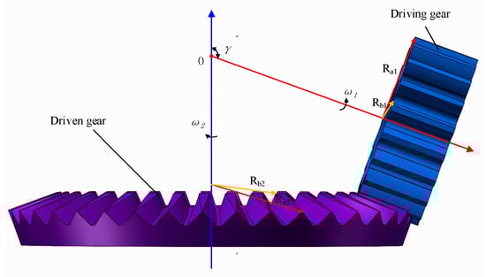
Figure 1.
Schematic diagram of contact of non-orthogonal face gear pair.
The working surface of a face gear is the envelope surface produced by the spatial meshing motion of the generated gears. Due to the end face characteristics of cylindrical gears, when the number of teeth is one to three less than that of tool gears, the contact between tooth surfaces can be regarded as point contact [30]. For detailed formula derivation, please refer to Appendix A. The contact equation is
Among them is the cylindrical gear:
where is the radius of the base circle of the cylindrical gear, is the motion parameter, , , and is the angle parameter of the involute tooth surface.
Among them is the face gear:
where is the rotation angle of the face gear, is the axial intersection angle,, , , , and .
Substitute Equations (2)–(5) into Equation (1), and solve to obtain all the coordinate points on the meshing contact trajectory. Shown in Figure 2 is a schematic diagram of the meshing trajectory.
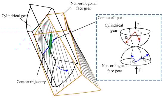
Figure 2.
Schematic diagram of the meshing trajectory of non-orthogonal face gear.
2.2. Loading Analysis of Non-Orthogonal Face Gear
2.2.1. Radius of Curvature at the Meshing Point
According to the theory of differential geometry principle, let and be two variables, and then the surface equation is expressed as
where , , is the unit vector of the coordinate axis of the coordinate system adopted, and the normal vector of the Gauss surface is as follows:
For a point on a surface, as shown in Figure 3, the vectors and are the tangent lines of the two coordinate curves on the surface, and is the direction of an infinitesimal displacement of a point along the surface. Angle the or variable parameter to the selected point , and is constant.
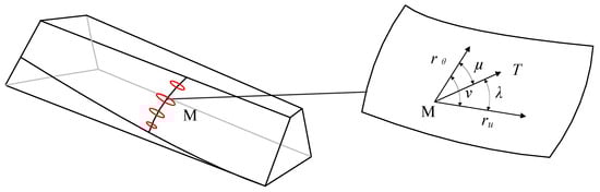
Figure 3.
Tangents of the coordinate curve of the meshing point.
The normal curvature equation is
where , , , and .
In order to determine the extreme value of , Equation (9) should satisfy . Thus, the formula is derived:
Two solutions of can be obtained from Equation (10), and by bringing the two solutions into Equation (9), the two principal curvatures of the surface can be found.
The curvature variation curves of cylindrical gear 1 and non-orthogonal surface gears can be obtained through solution. The curvature variation curve of the meshing point is shown in Figure 4. Among them, is the curvature of the cylindrical gear in the x direction, is the curvature of the cylindrical gear in the y direction, is the curvature of the face gear in the x direction, and is the curvature of the face gear in the y direction. It can be seen from Figure 4 that the signs of the two principal curvatures at the contact points on the tooth surfaces of non-orthogonal surface gears are opposite. This is because the points on the tooth surface of non-orthogonal surface gears are hyperbolic points.
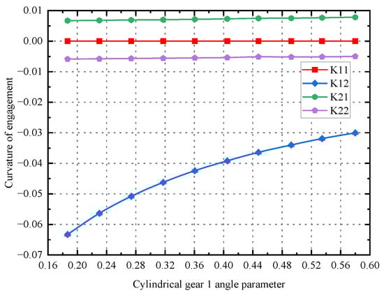
Figure 4.
Contact point curvature of non-orthogonal face gear.
2.2.2. Meshing Point Velocity
and are, respectively, the tooth surfaces of intermeshing cylindrical gears and non-orthogonal surface gears. Suppose at the initial moment, the two tooth surfaces are tangent at point ; after the movement of time , the two come into contact at another point , and their meshing state is shown in Figure 5.
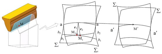
Figure 5.
Motion of two conjugate tooth surfaces.
Suppose that at a certain time, cylindrical tooth surface and face gear tooth surface are tangentially contacted at point . In the coordinate system, the vectors are denoted as and , respectively. In time , moves to and moves to , and the tangent point in space becomes point . The change in this position can be considered as that when tangent point moves to , it moves to point on . When moving to point on , the speed of the contact point moving along the respective tooth surfaces is and , respectively. The sliding coefficients and on the two tooth surfaces are
When taking the direction of as the same as the direction of the relative sliding speed , then there is , , . The expression of the sliding coefficient obtained from the solution is
The is derived as follows:
where ; ; is the discovery vector at the meshing point; is the angular speed of the cylindrical gear; is the difference in angular speed between the face gear and cylindrical gear; and is a Hamiltonian operator of .
From this, it can be derived that the sliding velocities and of the contact points along the tooth surfaces of cylindrical gears and face gears are, respectively,
Based on the rolling speeds at the meshing point of the cylindrical gear and at the meshing point of the face gear derived in the previous text, the suction speed at the meshing point can be calculated as
Shown in Figure 6 are the sliding speed and the roll speed at the meshing point of the cylindrical gear and the non-orthogonal face gear.
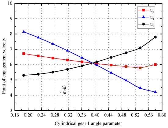
Figure 6.
Velocity change in meshing point of non-orthogonal face gear.
2.2.3. Meshing Point Load
As shown in Figure 7, during the meshing process of non-orthogonal face gears, the meshing force varies with the change in the rotation angle of the pinion. During the entire meshing process from meshing in (MI) to meshing out (MO), the gear pair undergoes an alternating cycle from double-tooth meshing to single-tooth meshing and then back to double-tooth meshing.
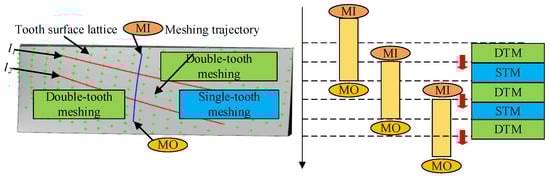
Figure 7.
Contact process of non-orthogonal face gear pair.
In Figure 7, curves and represent the projection curves of the meshing period transition point on the tooth surface. These curves can be regarded as meshing period transition curves. The variation in the meshing period leads to periodic fluctuations, and its maximum meshing force is
where is the load distribution coefficient that varies with the angle of rotation of the pinion. Its precise calculation is rather complex and can be obtained through the iterative method proposed in reference [31]. is the meshing period from the initial meshing to complete disengagement; is the number of teeth of the cylindrical gear; and and are, respectively, the angular positions of the cylindrical gear at the initial meshing and complete disengagement moments. and are the coordinate values of the non-orthogonal face gear on the shaft and on the shaft.
Substitute the working condition parameters into Equation (16), and write a MATLAB r2021a program for numerical solution to obtain the load parameters at the contact points during the meshing process, as shown in Figure 8.
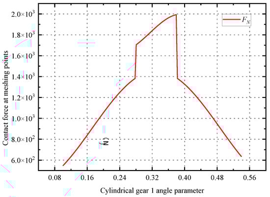
Figure 8.
Point contact force of non-orthogonal surface gear pair meshing.
2.3. Control Equation and Treatment of Point Contact Elastohydrodynamic Lubrication
To facilitate numerical solution, all control equations have undergone dimensionless and discretization processing. Dimensionless design aims to eliminate the influence of dimensions, reduce the number of variables, and enhance the universality of solutions. Discretization transforms the partial differential control equation into a system of linear algebraic equations that can be numerically solved. The basic dimensionless variable definitions adopted in this chapter are as follows: , , , , , , , , , . Here, is the dimensionless characteristic length.
Reynolds equation:
where is the pressure, is the oil film thickness, is the oil film thickness, is the viscosity, and is the enrolling speed.
Dimensionless and discrete processing of Reynolds equations:
where , , and . is the Reynolds coefficient, is the pressure at the grid points, is the dimensionless density, and is the dimensionless thickness of the steel film.
Energy equation:
where is the specific heat capacity at constant pressure, and is the heat conduction coefficient.
Dimensionless and discrete processing of energy equation:
where , , , and .
Boundary condition:
where is the initial temperature of the lubricating oil, and are the density of the material on the upper and lower surfaces, and are specific heat capacities, and are thermal conductivity, and and are velocities.
Film thickness equation and deformation equation ([32], Equation (2)):
where is the thickness of the central film before deformation, is the equivalent radius of curvature, is the elastic deformation displacement, is the quantity elastic modulus, is from the coordinate origin to , and is an uncertain constant, which can be ignored.
Dimensionless and discrete processing of film thickness equation and deformation equation:
Roelands equations for viscosity-pressure and viscosity-temperature:
Dimensionless processed viscosity-pressure and viscosity-temperature equation:
The maximum Hertz contact pressure under point contact conditions is ; is the pressure viscosity coefficient, which can be ; is usually preferred at 0.68; and usually refers to the dynamic viscosity, expressed in .
Density-pressure–density-temperature equation:
where is environmental density; and is the dense temperature coefficient, which is , , .
After the dimensionless,
2.4. Solution Method and Model Verification
This study adopts the finite difference method to numerically solve the Reynolds equation and the energy equation. The core idea is to transform partial differential equations into systems of linear algebraic equations through dimensionless and discretization processing, and thereby obtain stable solutions through numerical iteration. The computational domain is divided into an isometric grid. The differential term is approximated as the algebraic relationship between nodes by using the median difference formula, and then the oil film pressure and temperature distribution are solved point by point.
The solution process is based on the principle of iterative convergence. The pressure field is iterated by the Gauss–Seidel method, and the relative error of the results of two adjacent iterations is used as the convergence criterion. The temperature field is solved column by column based on the known pressure field and film thickness distribution, and low-relaxation iterations are introduced to ensure stability. Both set the upper limit of convergence accuracy and the number of iterations to balance computational efficiency and numerical accuracy.
Figure 9 illustrates the solution procedure for thermal EHL analysis of non-orthogonal face gear point contacts.
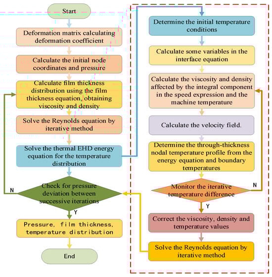
Figure 9.
Schematic diagram of the solution process for point meshing thermal EHL.
To verify the accuracy and reliability of the model constructed in this study, the academic achievements of Larsson [33] were selected as the benchmark for the reproduction research. It accurately restores the simulated environment in the original literature, covering boundary conditions, initial conditions, and key physical parameters. The simulation results of the model were systematically compared with the oil film thickness and pressure data reported in the literature (Figure 10). The results showed that the two were highly consistent, and the average absolute error of key parameters was less than 5%. This result confirmed the applicability and prediction accuracy of the model in this research field, providing a basis for the further application of the model.
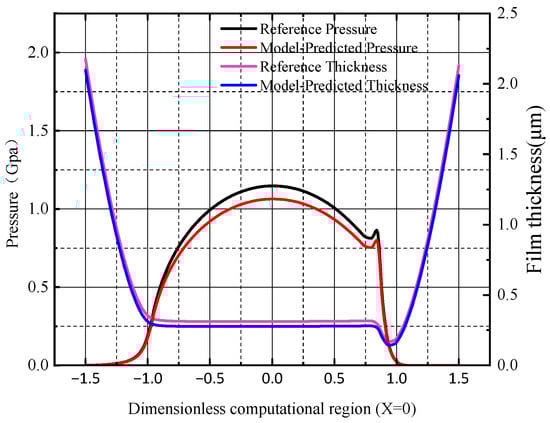
Figure 10.
Model verification and result comparison.
3. Results
3.1. Meshing Point Selection and Mesh Independence Verification
To achieve efficient calculation and physically representative analysis of time-varying lubrication performance, five discrete points on the contact path were selected for detailed TEHL analysis. These points, from S1 to S5, as shown in Figure 11, were selected based on the gear meshing theory to capture the typical stages of the meshing process. S1 is the double-tooth meshing entry node, S2 is the single-tooth meshing entry node, S3 is the node, S4 is the single-tooth meshing exit node, and S5 is the double-tooth meshing exit node.
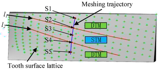
Figure 11.
Selection of meshing points for thermal elastohydrodynamic lubrication calculation.
Table 2 presents the parameters of non-orthogonal surface gears and lubricating oil required for calculating the thermoelastic flow. The lubricant used in this model is low-viscosity synthetic ester-based gear oil, equivalent to ISO VG 32.
Table 2.
Non-orthogonal gear pair and lubricant parameters.
To verify the independence of the grid, five sets of grids with different densities were designed. The S1 meshing point was calculated, and a series of calculations were carried out using the output oil film thickness, temperature rise, and pressure parameters as evaluation criteria. The results are shown in Table 3.
Table 3.
Non-orthogonal gear pair and lubricant parameters.
As shown in Table 3, when the grid density increases from grid 3 to grid 4, the change in the key results has become negligible. The grid was further encrypted to grid 5, but there was no significant change in the result. Therefore, based on the balance between computational accuracy and resource cost, we ultimately choose grid 4 as the grid scheme for all simulation calculations in this paper. This choice ensures that all the results reported in this paper are grid-independent and have sufficient computational accuracy.
3.2. Analysis of Oil Film at Meshing Points
Based on MATLAB programming and calculation, the three-dimensional isothermal distribution maps of the oil film at each point were obtained, and the results are shown in Figure 12.
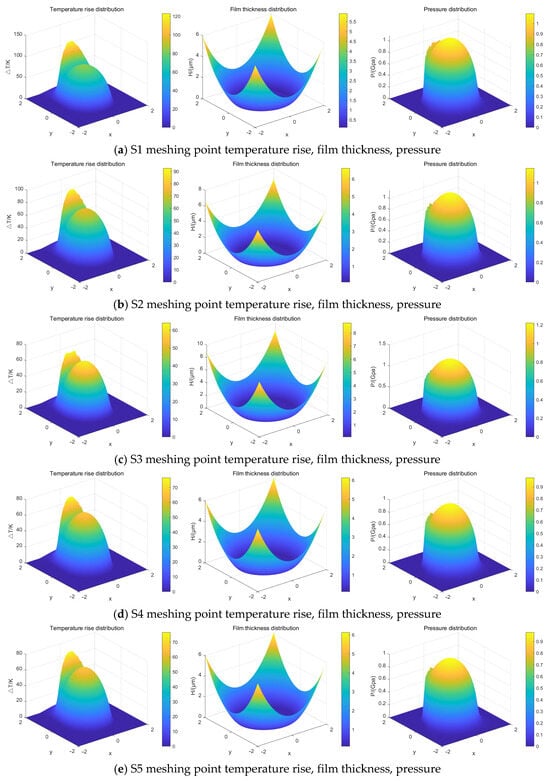
Figure 12.
Three-dimensional distribution of oil film characteristic parameters at the meshing point.
As shown in Figure 12, point S1 is located at the meshing-in side meshing point. At this location, the relative sliding velocity reaches its maximum, resulting in high frictional heat generation and a significant temperature rise in the oil film. At point S2, the relative sliding velocity decreases, leading to reduced heat generation at the meshing point. Meanwhile, due to an increase in load, the oil film pressure rises, and the film thickness correspondingly decreases. Point S3 is close to the pitch point, where the rotational speeds of the driving and driven gears are approximately equal, approaching pure rolling conditions. As a result, heat generation is minimized, and the temperature rise is the lowest. At point S4, as the load decreases and the relative sliding velocity increases again, the oil film pressure drops, the film thickness grows, and the temperature rise consequently increases. Finally, at point S5, the sliding velocity continues to rise while the load decreases, leading to a further increase in oil film thickness and a continued rise in temperature.
The maximum oil film pressure, minimum oil film thickness, and maximum oil film temperature rise are extracted from each meshing point as the characteristic values of the oil film. The eigenvalues of different points are compared, and the results are shown in Figure 13.
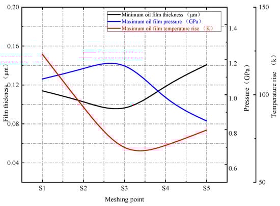
Figure 13.
Maximum pressure, minimum film thickness, and maximum temperature rise at meshing point.
As shown in Figure 13, during a single-tooth engagement cycle, the maximum pressure at the meshing point first decreases and then increases, influenced by the applied load and rotational speed. The minimum oil film thickness, in contrast, initially increases before decreasing. The maximum oil film temperature rise is governed by the slide-to-roll ratio (SRR) at the contact. It exhibits a trend of initial decrease followed by an increase, reaching its minimum at point S3, where the meshing condition approaches pure rolling.
As shown in Figure 13, the highest oil film temperatures were observed at the meshing-in and meshing-out points of the driving wheel. This phenomenon can be mutually verified with the flash temperature theory in lubrication. According to Blok’s [34] flash temperature theory, the local flash temperature at this point can be approximately expressed as
where is the coefficient of friction, is the Hertz contact pressure, is the sliding speed, and is the comprehensive thermal conductivity.
Analysis shows that the distribution of high-temperature areas obtained from numerical simulation is highly consistent with the high-risk areas predicted based on flash temperature theory. This strongly proves that the sharp temperature rise of the oil film at the meshing point is essentially due to the viscosity-pressure effect caused by high contact pressure, which leads to an increase in the viscosity of the grease, and then generates huge viscous dissipation under high sliding shear, ultimately manifesting as the local flash temperature.
3.3. Friction Coefficient of Tooth Surface
In the contact area of gear elastohydrodynamic lubrication, the shear rate endured by the lubricant usually exceeds 106 s−1. Under these extreme conditions, the lubricant exhibits significant non-Newtonian properties, especially the shear thinning phenomenon—the apparent viscosity decreases significantly with the increase in shear rate. To accurately describe this physical behavior, this study adopts the Ree–Eyring rheological model [35].
The calculation formula is as follows:
where is the ultimate shear stress of lubricating oil, and its value is .
Among them,
According to the above formula, the theoretical friction coefficients of the five grid points can be obtained, and the results are shown in Figure 12.
As shown in Figure 14, under the influence of the oil film characteristic parameter curves of the meshing point in Figure 13 on the sliding ratio, the friction coefficient is roughly distributed in a “V” shape due to the influence of the sliding–rolling ratio at the meshing point. When the relative sliding speed is low, the sliding–rolling ratio of the gear is S3 small, and the gear meshing is nearly in a pure rolling state, so the friction coefficient value at the meshing point is the smallest and close to 0. The sliding–rolling ratios on both sides are relatively large, so the friction coefficients at the meshing points S1 and S5 are larger.
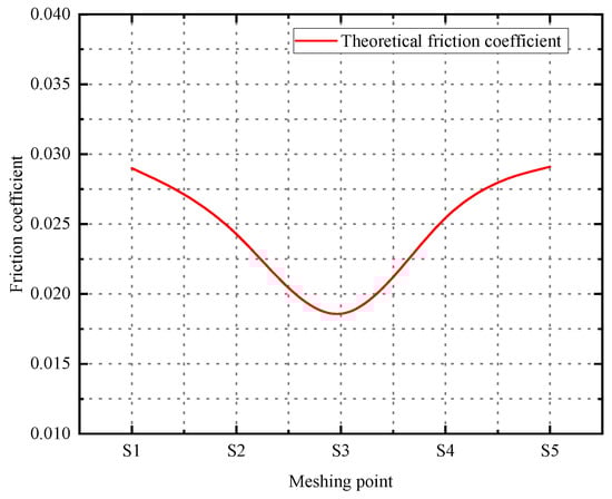
Figure 14.
Theoretical friction coefficient of meshing point.
To verify the accuracy of the variation trend of the theoretical friction coefficient, it is compared with the time-varying empirical formula of the friction coefficient of Xu [36]. The expression is as follows:
where is the sliding ratio, is the maximum Hertz contact stress, is the lubricating oil dynamic viscosity, is the entrainment speed, is the root mean square of roughness, and is the equivalent elastic modulus.
Based on a variety of empirical formulas of the friction coefficient, the formula is derived from the analysis of the shortcomings of each formula and a large number of experimental data of different working conditions, and it is suitable for the actual working conditions of most gears. According to the actual requirements of this paper, specific values are set for parameters in Equation (36), as shown in Table 4.
Table 4.
Assignment of empirical friction coefficient formula.
As shown in Figure 15, both theoretical and empirical friction coefficients exhibit a trend of initially decreasing and then increasing from the start of meshing at point S1 to the disengagement at point S5. Near the meshing point S3, the friction coefficient approaches zero, indicating that the gears are almost in a state of pure rolling. The differences in the calculation results mainly focus on the following two aspects. On the one hand, the roughness given by the empirical formula of the time-varying friction coefficient is a fixed value in the initial calculation, but the roughness of the tooth surface will change during the actual meshing process. On the other hand, the three-dimensional microscopic characteristics of the gear rough surface are neglected in the numerical calculation of thermoelastic flow.
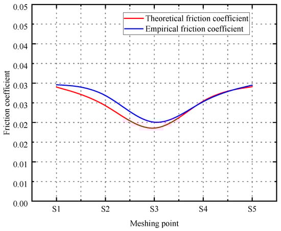
Figure 15.
Friction coefficient curve of meshing point.
3.4. Friction Heat Power
Based on the above calculation results, the thermal power distribution and tooth surface friction are numerically calculated.
The formula for calculating the instantaneous frictional heat power is as follows:
where is the time-varying friction coefficient, is the contact force at the point of engagement, unit , and is the relative sliding speed of the point of engagement, unit .
The calculation formula for the distribution of transient frictional heat power between the driving and driven wheels at the meshing point is
Among them,
where represents the distribution coefficient, and represents the thermal conductivity of the gear.
Shown in Figure 16 is the schematic diagram of the periodic thermal loading process. Let represent the meshing duration of the gear within the contact area at the given contact point, and represent the total meshing duration of the gear. Based on the transient frictional heat power, the steady-state frictional heat power can be derived:
where is the tangential velocity of the gear at the meshing point, with , is the half-width of the contact zone at the meshing point, and is the gear rotation period, .
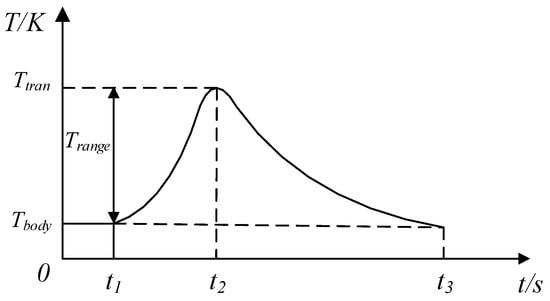
Figure 16.
Schematic diagram of periodic hot loading.
According to the above formula, the steady-state frictional heat power of the five meshing points is obtained, and the results are shown in Figure 17.
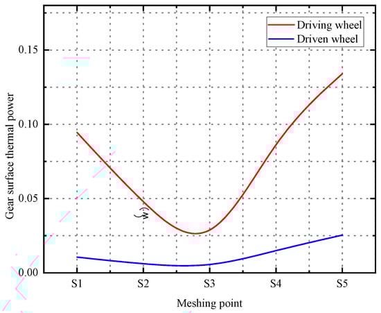
Figure 17.
Calculation results of steady-state frictional thermal power at the meshing point.
As shown in Figure 17, the frictional heat power demonstrates significantly higher values at both the engagement and disengagement sides, while dropping to nearly zero around the node S3. This distribution pattern can be attributed to the combined effect of the friction coefficient and relative sliding velocity, which collectively govern the frictional heat generation. Furthermore, under steady-state conditions, the cylindrical gear tooth surface experiences greater frictional heat power input compared with that on the non-orthogonal face gear.
Based on the calculated oil film pressure distribution and steady-state frictional heat power at different meshing points, the frictional heat power within the computational domain of the oil film at each meshing point is allocated according to the ratio of oil film pressure to the total pressure distribution. The results are presented in Figure 18.
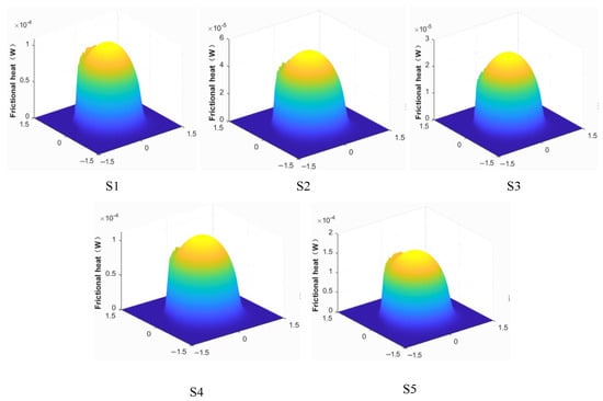
Figure 18.
The frictional heat power is distributed in three dimensions at the meshing point.
As shown in Figure 18, at the meshing point of S1 and S2, the friction coefficient gradually decreases, and the friction heat power gradually decreases. At the S3 meshing point, the gear close to the pure rolling friction coefficient is small, and friction heat power is minimal. The friction coefficient at the meshing point of S4 and S5 increases gradually, and the friction heat power increases gradually.
3.5. Analysis of Heat Transfer in Elastic Oil Films
3.5.1. The Oil Film Absorbs Heat and Generates Heat Through Friction
In point-line contact pairs such as gears and bearings, the transient temperature distribution within the elastohydrodynamic lubricating film is a key factor affecting their performance and failure. When lubricating oil is brought into and passes through the contact zone at high speed within the microsecond range, it undergoes intense shearing, resulting in the generation of an instantaneous internal heat source dominated by viscous dissipation [37]. However, due to the fact that the residence time of the lubricating oil in the contact zone is much shorter than the time required for thermal diffusion to reach a steady state, a uniform temperature field cannot be formed, thereby triggering local, rapidly fluctuating temperature peaks. This phenomenon is widely known as the “transient temperature flicker” or “flash temperature”.
The physical origin of this phenomenon can be traced back to the theory of moving heat sources. Jaeger’s [38] classic work laid the theoretical foundation for the calculation of the flash temperature in sliding contact. In the context of elastohydrodynamic lubrication, Greenwood and Kauzlarich [39] further clarified that in rolling contact, due to the extremely short contact time and the insufficient development of the thermal boundary layer, the transient flash temperature effect is particularly significant. With the development of experimental techniques, such as Ausherman et al.’s [40] direct observation of the elastic flow contact zone using infrared spectroscopy, it has been confirmed that there are indeed strong temperature fluctuations at the micrometer scale and microsecond level, providing direct evidence for the temperature “flicker” phenomenon observed in this study.
Given the extremely short time scale mentioned above, the heat generated within the lubricating film mainly dissipates through heat conduction into the relatively large and thermally conductive gear body. This heat distribution process can be described by the flash temperature theory proposed by Blok [34] and its subsequent developments (such as the work of Tian and Kennedy [41]). The core of this theoretical framework lies in regarding the contact area as a moving strip-shaped heat source, where heat is instantaneously and proportionally distributed to the two contact bodies. The distribution ratio depends on the thermal physical properties of the contact body material (thermal conductivity, density, specific heat capacity) and surface velocity. The Pecleiter number, which characterizes the relative importance of convection and conduction, is usually very high under these conditions. This indicates that the heat is mainly carried away by the volume convection of the moving surface; that is, the heat is first rapidly conducted to a very thin depth beneath the gear surface, then carried out of the contact zone by the rotating gear body, and finally, dissipated in other parts of the system. Therefore, the subsequent thermal analysis model of this paper is based on this recognized physical picture: that is, the thermal problem in the contact zone is dominated by viscous heat generation within the lubricating film, while heat dissipation is dominated by conduction and volume convection in the gear body.
In non-orthogonal face gear transmission, the viscous properties of the lubricating oil and the load and motion conditions of point contact promote the formation of an elastic lubricating oil film in the meshing area. Based on the calculation results of the oil film characteristic parameters at different meshing points, this paper selects the oil film characteristics of a specific meshing point to calculate the heat it absorbs.
The calculation formula for oil film absorption is as follows:
where is the specific heat capacity of the oil film, is the microcube oil film temperature rise, and is the mass of the microscopic cube oil film.
The oil film quality can be expressed as
where is the density of the oil film at different positions, is the thickness of the oil film at different positions, and calculates the step size of the partition in the domain.
Based on the aforementioned equation, the thermal energy absorbed by the oil film at five mesh points can be determined, with the computational outcomes illustrated in Figure 19.
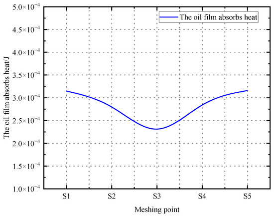
Figure 19.
Heat absorption curve of oil film at the meshing point.
Based on Hertz contact theory and the principle of sliding friction, a calculation model for the total frictional heat during gear meshing was established. For each discrete meshing point, the total frictional heat is calculated by the following formula:
where is the frictional heat power at the meshing point, and is the total heat generated by the friction at the meshing point.
The total frictional heat at the meshing points calculated is shown in Figure 20. The variation trend of the total frictional heat at the meshing points is mainly affected by the friction coefficient and the sliding speed, and it also shows a “V”-shaped distribution.
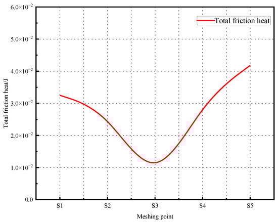
Figure 20.
Total heat generated by friction at the meshing point.
3.5.2. Comparative Analysis of Results
To quantify the contribution of heat transfer mediated by lubricating oil via forced convection heat exchangers within the gear heat exchange mechanism, a comparative analysis of the values at each meshing point is conducted. The findings from this comparison are presented in Figure 21 and Table 5.
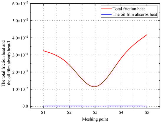
Figure 21.
Comparison of the total heat generated by friction at mesh point and heat absorbed by oil film.
Table 5.
Total friction heat and oil film heat absorption.
As shown in Figure 21 and Table 5, compared with the overall trend of total frictional heat generation, the heat absorbed by the oil film does or does not fluctuate significantly. In terms of magnitude, the heat absorbed by the oil film in the meshing zone is approximately 10−4, while the total frictional heat is about 10−2, indicating that the former only accounts for about 1% of the latter. At the moment of gear meshing contact and within the microscopic contact area, frictional heat is mainly dissipated through heat conduction. On a macroscopic level, when the high-temperature lubricating oil that has absorbed heat is carried out of the contact zone, it will dissipate the heat through convective heat transfer by coming into contact with other parts and the low-temperature lubricating oil.
4. Conclusions
This study systematically investigated the thermal elastohydrodynamic lubrication behavior of non-orthogonal surface gear transmission under point contact conditions and mainly reached the following conclusions:
- By establishing the tooth surface contact equation of non-orthogonal face gears, the meshing trajectory and curvature variation law are obtained. During the meshing process, the changes in sliding speed and rolling speed at the contact points significantly affect the lubrication state. The sliding speed near the node (point S3) is the smallest, approaching pure rolling.
- During the single-tooth meshing cycle, the maximum pressure of the oil film shows a trend of first decreasing and then increasing, while the minimum film thickness first increases and then decreases. The temperature rise is the lowest at the nodes, while at the meshing-in and meshing-out ends, due to the increase in sliding speed, the temperature rise increases significantly.
- The tooth surface friction coefficient calculated based on the Ree–Eyring model is close to zero at the nodes, and the friction coefficients at the meshing-in and meshing-out ends are relatively large, presenting a “V”-shaped distribution. The frictional heat power is the smallest at the node and reaches the maximum at the meshing-out end (point S5).
- Microscopic heat flow analysis at the meshing point reveals that at the moment of frictional heat generation with the source (Hertz contact zone), due to the extremely short contact time and extremely thin oil film, the proportion of heat absorbed through forced convection is very low (about 1%). This means that in the initial stage of heat generation, it mainly spreads rapidly into the metal interior through the heat conduction of the gear body. Subsequently, the large amount of heat conducted to the gear body and the small amount of heat entering the oil pool through convection are ultimately carried away by the lubricating oil circulating in the gearbox through convection, thereby achieving the overall thermal balance of the system.
Author Contributions
Conceptualization, X.C.; methodology, F.C.; software, F.C.; validation, X.C.; F.C.; formal analysis, J.W.; investigation, J.W.; resources, X.C.; data curation, J.W.; writing—original draft preparation, F.C.; writing—review and editing, X.C.; visualization, J.W.; supervision, X.C.; project administration, X.C.; funding acquisition, X.C. All authors have read and agreed to the published version of the manuscript.
Funding
This research was funded by the Natural Science Foundation Project of Liaoning Province (Grant No. 2025-MS-161), 2024 Fundamental Research Project (No. LJ212410154002) of the Educational Department of Liaoning Province, Basic Scientific Research Key Project of the Education Department of Liaoning Province (No. LJKZ0603), and Doctoral Research Start-up Fund Project of Liaoning Province (No. 2022-BS-308).
Data Availability Statement
These data were from simulations and actual experiments.
Acknowledgments
We would like to express our appreciation for the support provided by the research community, which has been instrumental in facilitating this work.
Conflicts of Interest
The authors declare no conflicts of interest.
Appendix A
Tooth surface equation of cylindrical gears (pinion):
where is the base circle radius of the tool gear, is the motion parameter, , and is the angle parameter of the involute tooth surface.
Tooth surface equation of non-orthogonal face gear:
where is the rotation angle of the face gear, is the axial intersection angle, , , , , and .
The contact equation is
Among them is the cylindrical gear:
where is the radius of the base circle of the cylindrical gear, is the motion parameter, , , and is the angle parameter of the involute tooth surface.
Among them is the face gear:
where is the rotation angle of the face gear, is the axial intersection angle, , , , , and .
According to the theory of differential geometry principle, let and be two variables, then the surface equation is expressed as
where , , is the unit vector of the coordinate axis of the coordinate system adopted, and the normal vector of the Gauss surface is as follows:
The normal curvature equation is
where , , and , .
In order to determine the extreme value of , Equation (3) should satisfy . Thus, the formula is derived:
The sliding coefficients and on the two tooth surfaces are
When taking the direction of as the same as the direction of the relative sliding speed , there is , , and . The expression of the sliding coefficient obtained from the solution is
The is derived as follows:
where ; ; is the discovery vector at the meshing point; is the angular speed of the cylindrical gear; is the difference in angular speed between face gear and cylindrical gear; and is a Hamiltonian operator of .
From this, it can be derived that the sliding velocities and of the contact points along the tooth surfaces of cylindrical gears and face gears are, respectively,
Based on the rolling speeds at the meshing point of the cylindrical gear and at the meshing point of the face gear derived in the previous text, the suction speed at the meshing point can be calculated as
The variation in the meshing period leads to periodic fluctuations, and its maximum meshing force is
where is the load distribution coefficient that varies with the angle of rotation of the pinion. Its precise calculation is rather complex and can be obtained through the iterative method proposed in reference [29]. is the meshing period from the initial meshing to complete disengagement; is the number of teeth of the cylindrical gear; and and are, respectively, the angular positions of the cylindrical gear at the initial meshing and complete disengagement moments. and are the coordinate values of the non-orthogonal face gear on the shaft and on the shaft.
The basic dimensionless variable definitions adopted in this chapter are as follows: , , , , , , , , , .
Reynolds equation:
where is the pressure, is the oil film thickness, is the oil film thickness, is the viscosity, and is the enrolling speed.
Substitute dimensionless
Discrete processing of Reynolds equations:
where , , and . is the Reynolds coefficient, is the pressure at the grid points, is the dimensionless density, and is the dimensionless thickness of the steel film.
Energy equation:
where is the specific heat capacity at constant pressure, and is the heat conduction coefficient.
Substitute dimensionless
Discrete processing of energy equation:
where , , , and .
Boundary condition:
where is the initial temperature of the lubricating oil, and are the density of the material on the upper and lower surfaces, and are specific heat capacities, and are thermal conductivity, and and are velocities.
Film thickness equation and deformation equation:
Substitute dimensionless
where is the thickness of the central film before deformation, is the equivalent radius of curvature, is the elastic deformation displacement, is the quantity elastic modulus, is from the coordinate origin to , and is an uncertain constant and can be ignored.
Dimensionless and discrete processing of the film thickness equation and deformation equation:
Roelands equations for viscosity-pressure and viscosity-temperature:
Dimensionless processed viscosity-pressure and viscosity-temperature equation:
The maximum Hertz contact pressure under point contact conditions is ; is the pressure viscosity coefficient, which can be ; is usually preferred at 0.68; and usually refers to the dynamic viscosity, expressed in .
Density-pressure–density-temperature equation:
where is environmental density; and is the dense temperature coefficient, which is , , .
After the dimensionless,
As shown in Figure 12, the highest oil film temperatures were observed at the meshing-in and meshing-out points of the driving wheel. This phenomenon can be mutually verified with the flash temperature theory in lubrication. According to Blok’s flash temperature theory, the local flash temperature at this point can be approximately expressed as
where is the coefficient of friction, is the Hertz contact pressure, is the sliding speed, and is the comprehensive thermal conductivity.
where is the ultimate shear stress of lubricating oil, and its value is .
Empirical coefficient of friction:
where is the sliding ratio, is the maximum Hertz contact stress, the is lubricating oil dynamic viscosity, is the entrainment speed, is the root mean square of roughness, and is the equivalent elastic modulus.
The formula for calculating the instantaneous frictional heat power is as follows:
where is the time-varying friction coefficient, is the contact force at the point of engagement, unit , and is the relative sliding speed of the point of engagement, unit .
The calculation formula for the distribution of transient frictional heat power between the driving and driven wheels at the meshing point is
Among them,
where represents the distribution coefficient, and represents the thermal conductivity of the gear.
where is the tangential velocity of the gear at the meshing point, with , is the half-width of the contact zone at the meshing point, and is gear rotation period, .
The calculation formula is as follows:
where is the specific heat capacity of the oil film, is the microcube oil film temperature rise, and is the mass of the microscopic cube oil film.
The oil film quality can be expressed as
where is the density of the oil film at different positions, is the thickness of the oil film at different positions, and calculates the step size of the partition in the domain.
The total frictional heat is calculated by the following formula:
where is the frictional heat power at the meshing point, and is the total heat generated by the friction at the meshing point.
References
- Ouyang, B.; Ma, F.; Dai, Y.; Zhang, Y. Numerical analysis on heat-flow-coupled temperature field for orthogonal face gears with oil-jet lubrication. Eng. Appl. Comput. Fluid Mech. 2021, 15, 762–780. [Google Scholar] [CrossRef]
- Pei, J.; Tian, Y.; Hou, H. Lubrication Reliability and Evolution Laws of Gear Transmission Considering Uncertainty Parameters. Lubricants 2025, 13, 392. [Google Scholar] [CrossRef]
- Sukumaran, J.; Ando, M.; Ando, P. Modelling gear contact with twin-disc setup. Tribol. Int. 2012, 49, 1–7. [Google Scholar] [CrossRef]
- Wassim, L.; Fathi, G.; Ali, A. Effects of interval friction coefficients on the differential mechanism dynamics. Proc. Inst. Mech. Eng. Part D J. Automob. Eng. 2022, 236, 3268–3295. [Google Scholar] [CrossRef]
- Hongu, J.; Horita, R. Estimation of Gear Friction Coefficient Using Directional Parameter of Tooth Surface. J. Tribol. 2022, 144, 011603. [Google Scholar] [CrossRef]
- Cao, W.; Tao, H.; Pu, W. Dynamics of lubricated spiral bevel gears under different contact paths. Friction 2022, 10, 247–267. [Google Scholar] [CrossRef]
- He, Z.X.; Wang, X.; Li, Y. Analysis of Gear System Dynamics Based on Thermal Elastohydrodynamic Lubrication Effects. Lubricants 2025, 13, 411. [Google Scholar] [CrossRef]
- Cheng, W.; Mao, K. A calculation method of sliding friction coefficient on tooth surface for helical gear pair based on loaded tooth contact analysis and elastohydrodynamic lubrication theory. J. Eng. Tribol. 2021, 235, 1551–1560. [Google Scholar] [CrossRef]
- Wang, Y.; Yang, W.; Tang, X. Friction coefficient analysis for herringbone gears based on dynamic meshing forces. J. Vib. Shock. 2021, 40, 265–272. [Google Scholar]
- Sheng, W.; Li, Z.; Yu, X.; Xue, A. Study on thermal elastohydrodynamic lubrication of face gear pairs with low sliding ratio. Mech. Based Des. Struct. Mach. 2024, 53, 3803–3822. [Google Scholar] [CrossRef]
- Pei, J.; Han, X.; Tao, Y.; Feng, S. Lubrication reliability analysis of spur gear systems based on random dynamics. Tribol. Int. 2021, 153, 106606. [Google Scholar] [CrossRef]
- Miltenovic, A.; Banic, M.; Vitkovic, N. Investigation of the Influence of Contact Patterns of Worm-Gear Sets on Friction Heat Generation during Meshing. Appl. Sci. 2024, 14, 738. [Google Scholar] [CrossRef]
- Hildebrand, S.; Genuin, T.; Lohner, T. Numerical analysis of the heat transfer of gears under oil dip lubrication. Tribol. Int. 2024, 195, 109652. [Google Scholar] [CrossRef]
- Wang, Y.; Niu, W.; Song, G. Convective heat transfer under different jet impingement conditions—Optimum design to spray parameters. Ind. Lubr. Tribol. 2016, 68, 242–249. [Google Scholar] [CrossRef]
- Wang, Y.; Niu, W.; Song, G.; Chen, Y. Convection heat transfer and temperature analysis of oil jet lubricated spur gears. Ind. Lubr. Tribol. 2016, 68, 624–631. [Google Scholar] [CrossRef]
- Zhou, W.; Zhu, R.; Liu, W.; Wang, J. Modeling and analysis of elastohydrodynamic lubrication of orthogonal face gear with installation errors. J. Eng. Tribol. 2024, 238, 956–970. Available online: https://sage.cnpereading.com/paragraph/article/?doi=10.1177/13506501241240023=0 (accessed on 3 October 2025). [CrossRef]
- Zhou, S.H.; Li, X.; An, C. An Improved Stiffness Model for Spur Gear with Surface Roughness Under Thermal Elastohydrodynamic Lubrication. Mathematics 2025, 13, 3335. [Google Scholar] [CrossRef]
- Liu, M.; Zhang, J. Thermal elastohydrodynamic lubrication analysis of helical gear pair under starved lubrication condition. Lubr. Sci. 2019, 31, 321–334. [Google Scholar] [CrossRef]
- Lu, Y.; Lu, X.; Ye, G.; Chen, Z. Thermal Failure Analysis of Gear Transmission System. J. Fail. Anal. Prev. 2024, 24, 520–537. [Google Scholar] [CrossRef]
- Mo, S.; Luo, B.; Dang, H.; Zhang, Y. Lubrication characteristic of tooth surface on arc tooth cylindrical gears. Lubr. Sci. 2023, 35, 14–28. [Google Scholar] [CrossRef]
- Xu, Q.; Yan, W.; Chen, S. Optimization of splash lubrication in the gearbox considering heat transfer performance. Tribol. Int. 2024, 195, 109592. [Google Scholar] [CrossRef]
- Xu, Q.; Liu, C.; Zhang, S.; Yan, W.; Li, X. Mathematical modeling and numerical simulation of jet torque. Int. J. Mech. Sci. 2024, 277, 109439. [Google Scholar] [CrossRef]
- Xu, Q.; Zhang, S.; Yang, K.; Chen, W. Strategy of directional oil transport for splash lubrication systems. Int. J. Mech. Sci. 2024, 269, 109059. [Google Scholar] [CrossRef]
- Hu, X.; Yuan, Y.; Chen, J. Study on Temperature Field Distribution of a High-Speed Double-Helical Gear Pair with Oil Injection Lubrication. Lubricants 2024, 12, 315. [Google Scholar] [CrossRef]
- Ding, H.; Zhang, W.; Wu, H.; Chen, T. Multi-field coupling lubrication interface heat transfer model for hypoid gear transmission. Int. Commun. Heat. Mass. Transf. 2024, 154, 107451. [Google Scholar] [CrossRef]
- Chu, X.; Liu, Y.; Zeng, H. Study on Heat Transfer Characteristics of High-Speed Herringbone Gear in Meshing Process Under Oil Injection Lubrication. J. Therm. Sci. Eng. Appl. 2024, 16, 041010. [Google Scholar] [CrossRef]
- Sun, Z.; Yao, Q.; Jin, H. A novel in-situ sensor calibration method for building thermal systems based on virtual samples and autoencoder. Energy 2024, 297, 131314. [Google Scholar] [CrossRef]
- Sun, Z.; Yao, Q.; Shi, L. Virtual sample diffusion generation method guided by large language model-generated knowledge for enhancing information completeness and zero-shot fault diagnosis in building thermal systems. J. Zhejiang Univ. Sci. A 2025, 26, 895–916. [Google Scholar] [CrossRef]
- Liu, L.; Wu, S. Generation and contact of modified non-orthogonal offset face gear drives. Int. J. Mech. Sci. 2025, 300, 110314. [Google Scholar] [CrossRef]
- Zhu, R. Research on Meshing Characteristics of Face Gear Drives. Ph.D. Dissertation, Nanjing University of Aeronautics and Astronautics, Nanjing, China, 2000. [Google Scholar]
- Mo, S.; Song, W.; Zhang, Y.; Zhou, Y.; Yao, B. A new iterative method for calculating the time-varying meshing stiffness of orthogonal face gear pairs. Mech. Mach. Theory 2025, 206, 105938. [Google Scholar] [CrossRef]
- Lugt, P.M.; Guillermo, E.M. A Review of Elasto-Hydrodynamic Lubrication Theory. Tribol. Trans. 2011, 54, 470–496. [Google Scholar] [CrossRef]
- Larsson, R. Transient non-Newtonian elastohydrodynamic lubrication analysis of an involute spur gear. Wear 1997, 207, 67–73. [Google Scholar] [CrossRef]
- Blok, H. The flash temperature concept. Wear 1963, 6, 483–494. [Google Scholar] [CrossRef]
- Wang, Y.Q.; Yi, X.J. Non-Newtonian transient thermoelastohydrodynamic lubrication analysis of an involute spur gear. Lubr. Sci. 2010, 22, 465–478. [Google Scholar] [CrossRef]
- Hai, X. Development of a Generalized Mechanical Efficiency Prediction Methodology for Gear Pairs. Ph.D. Dissertation, The Ohio State University, Columbus, OH, USA, 2005. [Google Scholar]
- Spikes, H.A. Sixty years of EHL. Lubr. Sci. 2006, 18, 265–291. [Google Scholar] [CrossRef]
- Jaeger, J.C. Moving sources of heat and the temperature at sliding contacts. J. Proc. R. Soc. New South Wales 1943, 76, 203–224. [Google Scholar] [CrossRef]
- Greenwood, J.A.; Kauzlarich, J.J. Inlet Shear Heating in Elastohydrodynamic Lubrication. J. Lub. Technol. 1973, 95, 417–423. [Google Scholar] [CrossRef]
- Ausherman, V.K.; Nagaraj, H.S. Infrared Temperature Mapping in Elastohydrodynamic Lubrication. J. Lub. Technol. 1976, 98, 236–242. [Google Scholar] [CrossRef]
- Tian, X.; Kennedy, F.E. Maximum and Average Flash Temperatures in Sliding Contacts. J. Tribol. 1994, 116, 167–174. [Google Scholar] [CrossRef]
Disclaimer/Publisher’s Note: The statements, opinions and data contained in all publications are solely those of the individual author(s) and contributor(s) and not of MDPI and/or the editor(s). MDPI and/or the editor(s) disclaim responsibility for any injury to people or property resulting from any ideas, methods, instructions or products referred to in the content. |
© 2025 by the authors. Licensee MDPI, Basel, Switzerland. This article is an open access article distributed under the terms and conditions of the Creative Commons Attribution (CC BY) license.