Abstract
To develop a new porous metal for aerostatic bearing, herein, novel porous thin plates (PTPs) with micron-scale porous structures are fabricated. The pore size distribution and air permeability of PTPs are measured. A tensile test is carried out and the fractography is observed. The load capacity and stiffness of aerostatic bearings utilizing PTPs as porous restrictors are tested. The results show that the phenomenon of the uneven distribution of powders can be significantly improved by decreasing the roller speed. Fine powder porous thin plates (FPTPs) effectively balance permeability and mechanical properties, achieving an ultimate tensile strength of 157 MPa while maintaining favorable permeability, significantly exceeding existing porous restrictors. Aerostatic bearings employing PTPs as restrictors demonstrate substantial load capacity and stiffness. Notably, aerostatic bearings utilizing coarse powder porous thin plates (CPTPs) as restrictors deliver 511 N load capacity and 22 N/μm stiffness with a considerably smaller porous restrictor area. It is worth noting that the novel PTPs not only exhibit a straightforward and environmentally friendly manufacturing process but also preserve the micron-scale porous structure while meeting the practical requirements of aerostatic bearings, holding significant promise for gas lubrication applications.
1. Introduction
Porous materials integrate the characteristics the advantages of being lightweight, having multiple pores, and having a large specific surface area [1], and are widely used in electromagnetic shielding, filtering, and other fields [2,3]. With the expansion of application, higher requirements are put forward for the permeabilities and mechanical properties of porous materials. For example, in the field of fluid lubrication, because aerostatic bearings use high-pressure gas as the lubricant, there is no contact between the bearing and the loading surface during operation. Therefore, this lubrication approach has the characteristics of high precision, low loss, and no pollution and is one of the core parts of ultrahigh-speed and ultra-precision processing equipment [4,5]. To obtain excellent loading performance of the aerostatic bearings, Belforte et al. [6] used the traditional method processing micron-sized holes on the metal substrate for throttling, but this requires high machining accuracy. Guo et al. [7] fabricated an aerostatic bearing by machining an array of micro-holes on metallic materials and analyzed the effects of various parameters on its load capacity and mass flow rate in a vacuum environment. This study demonstrated that an increase in the pressure differential across the bearing enhances its load capacity. However, this method of machining micro-holes suffers from complex processes, high manufacturing costs, and still offers substantial room for improvement in the bearing’s load capacity. Li et al. [8] employed porous graphite as a restrictor in an aerostatic bearing and systematically investigated the impact of surface damage on the porous bearing’s performance. The results revealed that the damage caused a marked reduction in local pressure within the bearing clearance, resulting in lower load capacity and stiffness for the damaged bearing compared to its undamaged counterpart. Zhang et al. [9] used porous graphite and porous ceramics as restrictors. However, graphite has low tensile strength, and porous ceramics have high brittleness and are difficult to process, which seriously limits the development of aerostatic bearings. Therefore, it is necessary and significant to develop porous materials with excellent permeability and mechanical properties that are lightweight and suitable for large-scale production.
In recent years, lightweight and functionally porous materials reported in the literature have mainly focused on porous polymers [10], porous carbon fibers [11], and porous ceramics [12]. However, porous polymers are not resistant to high temperature and wear, porous carbon fibers have high brittleness and high production cost, and porous ceramics have low mechanical properties and are easy to destroy. There are many manufacturing methods for porous materials, including chemical deposition [13], coating [14], and elective laser melting [15]. Chemical deposition has disadvantages of high energy consumption, expensive exogenous gas, and high safety risk. The bonding strength of the coating from the substrate is low, and cracks easily occur. Increasing the porosity is considered to be an effective method to improve the permeability of porous materials. However, the pores contain a large number of obturator holes, which make the material less permeable. Santhosh et al. [16] found that with the increase in porosity, the structures that can be used to bear load per unit volume decrease and provide more possibilities for crack initiation, resulting in a sharp decline in the mechanical properties of the material. Therefore, it is difficult for traditional porous materials to consider both permeability and mechanical properties. However, the increase in porosity also has beneficial effects. For instance, Zhu et al. [17] fabricated metal porous materials by selective laser melting technology with 316 L stainless steel powders as raw materials. The results showed that with the increased in laser exposure time, the number of pores decreased. The porous structure of the samples was useful to reduce the coefficient of friction, which had a positive effect on lubrication. Roque et al. [18] prepared porous scaffolds with sufficient mechanical properties using 3D printing technology, which can be used in the tissue engineering field. Tang et al. [19] fabricated ultra-thin heat pipes using copper mesh as raw material by oxidation treatment and sintering. The experimental results show that the porous structure of the oxidized mesh significantly improves the heat transfer performance of the ultra-thin heat pipe.
Nevertheless, the composite rolling process of coarse powder and wire mesh is an unsolved problem and has not been studied. The application of powder wire mesh composite porous material in the field of fluid lubrication has not been reported. The main purpose of this paper is to realize the composite rolling process of coarse powder and wire mesh, and to develop a new type of porous material that can give consideration to both the air permeability and mechanical properties, and then to verify its application of fluid lubrication. Coarse metal powder and wire mesh are resistant to high temperature, and wire mesh, as a continuous fabric structure, has the function of enhancing material permeability and mechanical properties. As a powerful plastic forming method, rolling can significantly increase the deformation degree of materials, provide conditions for forming a large metallurgical bonding surface area, and improve the mechanical properties of materials [20].
In this work, we solved the problem of coarse powder and wire mesh composite, and prepared new types of PTPs. The pore size distribution, air permeability, and tensile properties of the PTPs were tested. The surface morphology and fractography were observed, and the fracture mechanism was analyzed. The PTPs were applied to aerostatic bearings. Therefore, this opens up new possibilities for the application of porous metal materials in the gas lubrication field.
2. Materials and Methods
2.1. Preparation of the PTPs
The 304 stainless steel powder with an irregular shape in the diameter range from 240 to 450 μm was used in the experiment. The 304 stainless steel wire mesh had a diameter of 100 μm. Scanning electron microscope (SEM) images are shown in Figure 1. In the traditional method of powder rolling, the powder is dry before entering the rolling area; thus, the powder can flow freely, and the process can be considered a dry process rolling method. To determine the appropriate rolling speed, first, coarse diameter 304 stainless steel powder and wire mesh were dry rolled. The rolling speeds were 8 r/min, 2 r/min, and 1 r/min. The rolling process was carried out on a custom-designed horizontal mill (roller diameter of 122 mm, rolling force of 50 tons, rolling gap of 0 mm). The specific rolling process is as follows: first, 304 stainless steel wire mesh was placed below the hopper. Then, the baffle was adjusted to the appropriate position to control the thickness of the powder to 1 mm. After that, the powder was poured into the hopper. Adopting roll rotation, the wire mesh is gradually dragged into the rolling area. The powder was driven by the wire mesh and gradually laid on the wire mesh. By adjusting the frequency converter on the mill, the roll speed can be accurately controlled. The essential difference between wet process rolling and dry process rolling is that before the wire mesh enters the rolling area, a nozzle is used to spray water mist to wet the powder. The wet process rolling of the coarse powder porous thin plates (CPTPs) are shown in Figure 1. Our previous study [21] demonstrated that fine powders (diameter range from 50 to 90 μm) can be rolled with wire mesh under dry conditions. Water mist condenses into droplets and floats in the powder layer when water mist is sprayed on a fine powder layer. Therefore, dry process rolling was used to produce fine powder porous thin plates (FPTPs) using a fine powder and a wire mesh. Because of the large powder diameter, the CPTPs easily cracked on the surface when the plates were bent. To avoid cracks at the plates, two layers of CPTP were annealed and then subjected to composite rolling, followed by vacuum sintering. The annealing process was as follows: First, the CPTPs were put into a vacuum sintering furnace (WHS-20, Kaixuan vacuum technology and Engineering Co., Ltd., Zhongshan, China) with a vacuum degree of approximately 5 × 10⁻² Pa. The CPTP was heated to 900 °C at a rate of 10 °C/min and held for 2 h. The vacuum sintering process was as follows: First, the furnace was heated to 800 °C at 5 °C/min, then continued to 1310 °C at 4 °C/min and held for 2 h. Then, the temperature was reduced to 800 °C at 5 °C/min. Finally, the CPTP was cooled to room temperature.
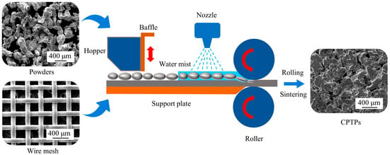
Figure 1.
Schematic diagram of wet process rolling of the CPTP.
2.2. Preparation of the Aerostatic Bearing and Load Capacity Measurement
Figure 2 shows the schematic diagram of the aerostatic bearing load capacity measurement system. As shown in Table 1, the bearing has a diameter of 50 mm, with the porous material diameter of 24 mm. The CPTP thickness is 0.91 mm (porosity: 35.16%), and the FPTP thickness is 0.35 mm (porosity: 25.93%). The measured permeability values for the PTPs are presented in Table 2. The specific structure of the aerostatic bearing is shown in Figure 3b. The bearing’s load-bearing surface was sequentially polished using sandpaper of different grit sizes, followed by polishing with diamond suspension to achieve a surface roughness below Ra 0.8 μm. Since ground-flat alumina plates were placed on both sides of the PTPs during sintering to ensure their flatness, the PTP surfaces were not polished. Then, the PTPs were cut into a circular sample with a diameter of 24 mm and pasted onto the bearing housing with metal welding adhesive. The plenum chamber connects to a quick-connect fitting via a threaded hole, allowing for high-pressure gas to flow into the chamber and supply the aerostatic bearing (Figure 3b). The load capacity was tested on an electronic universal testing machine (UTM) (UTM5105SYXL, Suns, Shenzhen, China) (Figure 3a). The air-lubricated bearing surface was placed on the lower load plate, and the lower load plate was fixed on the UTM movable beam. The bearing housing was aligned with the center of the upper load plate. To prevent measurement inaccuracies caused by bearing tilt, a 10 mm diameter universal ball hinge (Figure 3a) between the support rod and upper loading plate was installed, enabling automatic tilt compensation to ensure measurement accuracy. The universal ball hinge keeps the air-lubricated bearing surface parallel with the lower load plate. The eddy current displacement sensor (TR-810504, Zhuzhou Liulingba Technology and Science Co., Ltd., Zhuzhou, China) was fixed on the beam of the UTM with a magnetic base and was aligned with the upper load plate. During the test process, first, the air-lubricated bearing surface was pressed on the lower load plate, and the air pressure was set to 0.3 MPa, 0.4 MPa, and 0.5 MPa, sequentially. The air film thickness between the air-lubricated surface and the lower load plate was controlled by the movement of the beam. The air film thickness h was calculated by Equation (1).
where h is the air film thickness (μm); l1 is the initial value (μm); l2 is the test value (μm).
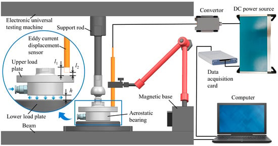
Figure 2.
Schematic diagram of the aerostatic bearing load capacity measurement system.

Table 1.
Design parameters of aerostatic bearings.

Table 2.
The pore size and air permeability of the PTPs.
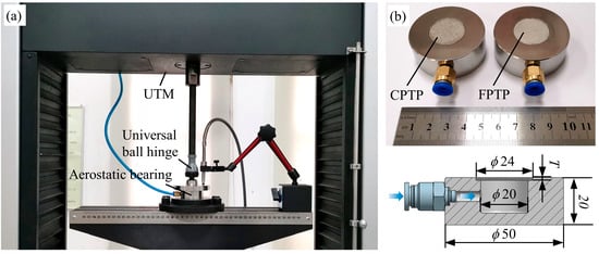
Figure 3.
Test site of the load capacity measurement system and of the aerostatic bearing. (a) Load capacity measurement system; (b) aerostatic bearings.
The eddy current displacement sensor was connected to a convertor (TR-810500, Zhuzhou Liulingba Technology and Science Co., Ltd., Zhuzhou, China) and a 15 V DC power source (WB-8178, Zhuzhou Liulingba Technology and Science Co., Ltd., Zhuzhou, China). The collected voltage signal was transmitted to the computer by an NI data acquisition card (USB-6361, National Instruments, Austin, TX, USA). The load capacity was collected by the UTM. The test program was programmed by NI LabVIEW, and the air film thickness value was displayed on a computer.
2.3. Characterization
The surface morphology of the PTPs was observed by SEM (Quanta 200, FEI, Eindhoven, The Netherlands). The porosity of the PTPs was tested by the quality volume method [22] according to Equation (2).
where m is the mass of the sample (g), v is the volume of the sample (cm3), and ρ is the density of 304 stainless steel (7.93 g/cm3).
Based on the bubble point method [23], an aperture analyzer (PSDA-20, GaoQ Functional Materials Co., Ltd., Nanjing, China) was used to measure the pore size distribution characteristics of the PTPs. Air permeability is one of the basic characteristics of porous materials, reflects the ability of air to pass through porous media under a pressure difference, and plays a very important role in the filtering and throttling field. The fluid flows through porous materials in a laminar flow state and obeys Darcy’s law [24] under the situation of a low flow rate. With the increase in flow velocity, the fluid is prone to turbulence in the curved pore structure; thus, Forchheimer modified Darcy’s law and gave an accurate relationship [25], as shown in Equation (3).
where Po is the absolute outlet air pressure (101,325 Pa); Pi is the absolute inlet air pressure (Pa); L is the thickness of the porous materials (m); μ is the viscosity of the air (1.79 × 10⁻⁵ Pa·s); ρ is the air density (1.205 kg/m3); K1 is the Forchheimer permeability coefficient (m2); K2 is the inertial permeability coefficient (m); and vf is the average velocity of airflow (m/s).
The experiment was carried out in the gas permeability test system [26] of porous materials designed according to Darcy’s law, and the values of K1 and K2 could be obtained by fitting the air velocity and pressure difference data according to the least squares method [27]. The tensile properties of the specimens were tested according to Chinese GB/T 228.1-2010. The tensile specimens were sampled along the rolling direction with a width of 5 mm, a gauge length of 10 mm, and a transition fillet radius of 10 mm. The tensile test was conducted on an electronic UTM (UTM5105SYXL, Suns, China) at a tensile rate of 0.1 mm/min. Three specimens were used, and the average results were taken as the test results. SEM (Quanta 200, FEI, The Netherlands) was used to observe the fractography of the PTPs. The stiffness of the aerostatic bearing is defined as the incremental rate of its load capacity with respect to the air film thickness, as given in Equation (4).
where Δw is the variation of the aerostatic bearing’s load capacity and Δh is the variation of the air film thickness.
3. Results and Discussion
3.1. Fabrication and Surface Microtopography Characterization
Figure 4 shows the influence of the roller speed and wet process rolling on the CPTPs. When the roller speed was 8 r/min, the coarse powder and wire meshes were rolled to form an obvious crescent-shaped defect (Figure 4a). This phenomenon is because the large diameter powder was sensitive to the warpage of the wire mesh, and it was easy to roll and gather in the rolling process. On the other hand, the roller speed was faster, and the wire mesh warping deformation speed was accelerated so that the coarse powder quickly slipped and gathered (Figure 4c), forming a powder distribution with uneven crescent-shaped defects along the rolling direction (RD). When the roller speed was 2 r/min (Figure 4b), the crescent-shaped defects were reduced and gradually fused, and the uneven coarse powder distribution was improved. This result is because with the deceleration of the roller, the wire mesh warping speed slowed down. This slows the powder slide speed. Part of the powder from the wire mesh gathered, forming crescent-shaped defects. The other powders with the wire mesh pass through the rolling area, forming the powder wire mesh composite structure. When the roller speed decreased to 1 r/min (Figure 4d), the crescent-shaped defects nearly disappeared, and the uneven distribution of the powders was significantly improved. This is because the further reduction in speed significantly reduced the wire mesh warping speed, which is conducive to the stable laying of powder in the wire mesh and improves the uneven distribution phenomenon of the powders. Figure 4e shows the rolling effect with a roller speed of 1 r/min and assisted by wet process rolling. The crescent-shaped defects disappeared completely. The powder was observed to be evenly distributed on the wire mesh after water mist wetting. The water mist makes the powders bond to each other. Furthermore, the water mist enhances the friction between the powder and the wire mesh [28]. The powder was combined into a temporary fixed sheet under the action of water mist, which could be warped with the warpage of the wire mesh (Figure 4f). The above analysis shows that reducing the roller speed could significantly improve the uneven distribution phenomenon of the powder, and wet process rolling could further eliminate this uneven distribution. In summary, reducing the roller speed and using the wet process rolling could effectively realize the composite rolling of the coarse powder and wire mesh.
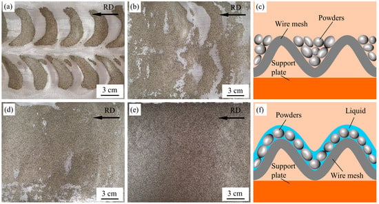
Figure 4.
The influence of the roller speed and wet process rolling on the CPTPs: (a) 8 r/min; (b) 2 r/min; (c) schematic diagram of the dry process rolling; (d) 1 r/min; (e) wet process rolling; (f) schematic diagram of wet process rolling.
Figure 5 shows the surface morphology of the PTPs. The CPTP upper surface had gaps between powders (Figure 5a), in contrast to the metallurgical bonding between powders of FPTP (Figure 5c). This phenomenon is because, under the same rolling force, the deformation of powder with a large diameter was smaller than that of powder with a small diameter, and the original gap between individual powder particles was larger. Additionally, the surface energy of powder with a large diameter was lower than that of powder with a small diameter [29], and the metallurgical bonding degree between powders was lower under the same sintering conditions. Both CPTP and FPTP had a large number of pores on their upper surfaces. The difference is that the pore size of CPTP is larger than that of FPTP. The microstructure of the lower surface of CPTP shows that there is an obvious metallurgical bonding point between the powder and the wire mesh (Figure 5b), but there is an obvious gap between the wire mesh and the wire mesh. The essential reason is that the large diameter wire mesh was less prone to deformation in the rolling process, and its surface energy was lower than the similar size of the powder, so the metallurgical bonding between the wire mesh was low. Figure 5d shows that the degree of metallurgical bonding between the powder and wire mesh was obviously weaker than that between the two powders. Because the wire mesh is a continuous dense material, its shape was more regular, and the surface energy was lower than that of the powders. Thus, the powders with higher surface energy were easier to metallurgically combine in the sintering process [30]. Figure 5 shows the surface morphology of the PTPs. The CPTP upper surface had gaps between powders (Figure 5a), in contrast to the metallurgical bonding between powders of FPTP (Figure 5c). This phenomenon is because, under the same rolling force, the deformation of powder with a large diameter was smaller than that of powder with a small diameter, and the original gap between individual powder particles was larger. Additionally, the surface energy of powder with a large diameter was lower than that of powder with a small diameter [29], and the metallurgical bonding degree between powders was lower under the same sintering conditions. Both CPTP and FPTP had a large number of pores on their upper surfaces. The difference is that the pore size of CPTP is larger than that of FPTP. The microstructure of the lower surface of CPTP shows that there is an obvious metallurgical bonding point between the powder and the wire mesh (Figure 5b), but there is an obvious gap between the wire mesh and the wire mesh. The essential reason is that the large diameter wire mesh was less prone to deformation in the rolling process, and its surface energy was lower than the similar size of the powder, so the metallurgical bonding between the wire mesh was low. Figure 5d shows that the degree of metallurgical bonding between the powder and wire mesh was obviously weaker than that between the powders. Because the wire mesh is a continuous dense material, its shape was more regular, and the surface energy was lower than that of the powders. Thus, the powders with higher surface energy were easier to metallurgically combine in the sintering process [30].
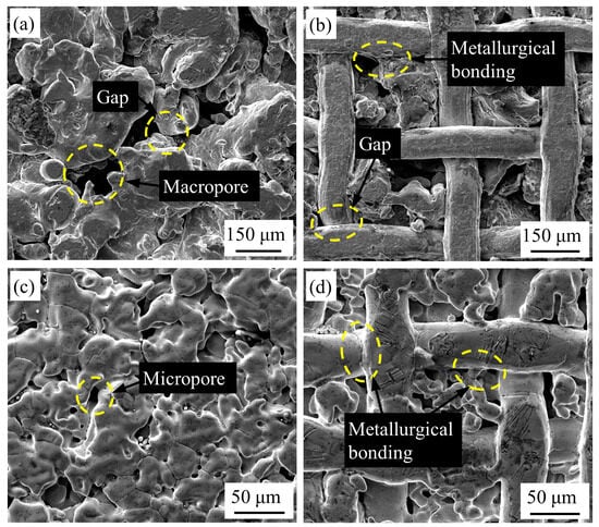
Figure 5.
Surface morphology of the PTPs. (a) Upper surface of CPTP; (b) lower surface of CPTP; (c) upper surface of FPTP; (d) lower surface of FPTP.
3.2. Air Permeability and Tensile Mechanical Properties of the PTPs
Figure 6 shows the pore size distribution and air permeability of the PTPs. The pore size cumulative distribution curves of the CPTP (Figure 6a) show that approximately 95% of pores were smaller than 40 μm. Among them, the pore size of 1.9 μm accounted for the highest proportion at 15.4% (Figure 6a), while the average pore size was 17.6 μm (Table 2). The pore size of the CPTP was large and unevenly distributed. Approximately 70.6% of the pores of the FPTP were distributed between 2.4 and 3 μm (Figure 6b). The pore size of 2.7 μm accounted for the highest proportion at 63.6%, and the average pore size of the FPTP was 2.9 μm (Table 2). These results show that the pores of the FPTP were small and evenly distributed.
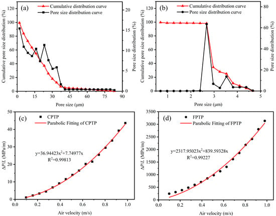
Figure 6.
Pore size distribution and flow velocity differential pressure curves of the PTPs. (a,c) CPTP; (b,d) FPTP.
Figure 6c,d show the flow velocity differential pressure curves of the CPTP and FPTP, respectively. The pressure difference tends to increase nonlinearly with increasing air velocity. This result is because with the increase in air velocity, the energy dissipated by the friction between the gas and curved channel increases, leading to a nonlinear increase in the pressure difference. The pressure difference of the FPTP was higher than that of the CPTP. The average pore size of the FPTP was significantly smaller than that of the CPTP. The smaller pore size hinders the smooth passage of gas, making the pressure difference larger. Table 2 shows that the Forchheimer permeability coefficient and inertia permeability coefficient of the CPTP were higher than those of the FPTP. This result is because the CPTP powders were significantly larger than those of the FPTP, which was conducive to the formation of porous CPTP structures with larger pore sizes and simpler pore structures. The larger pore structure was favorable for the smooth passage of gas. In addition, the simple pore structure reduced the dissipation of frictional energy between gas and pore channels [27], which was conducive to the reduction in gas pressure. Therefore, the CPTP had better air permeability than the FPTP.
Figure 7 shows the tensile properties and the comparison performance parameters of the PTPs. The fracture stage of the PTPs was slightly longer than the elastic stage (Figure 7a). This phenomenon occurred because the deformation of the wire mesh [31] and the asynchronism between the wire mesh and powder fracture process prolonged the fracture stage of the PTPs. Figure 7b shows that the ultimate tensile strength (UTS) and elongation of the FPTP were 157 MPa and 11.2%, respectively, which were significantly better than those of CPTP (23 MPa and 3.9%, respectively). This result is because the fine powder and wire mesh deform to a greater degree than the coarse powder and wire mesh (Figure 4) and were close enough to each other to establish metal bonds [32], which facilitated diffusion bonding of metal atoms during vacuum sintering. In addition, fine powder and wire mesh have higher surface energy than coarse powder and wire mesh, which was conducive to the growth and fusion of the sintering neck and promoted the mechanical properties of the FPTPs.
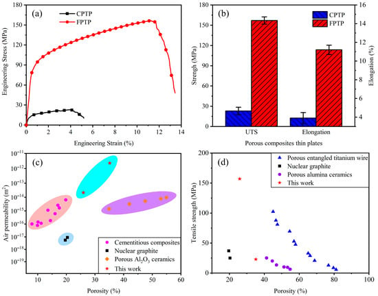
Figure 7.
The tensile properties and summary performance of the PTPs. (a) Engineering stress–strain curves; (b) tensile properties; (c) summary air permeability; (d) summary tensile strength.
Figure 7c shows the air permeability of porous materials according to this work and previous reports. The air permeability of the CPTP was significantly better than that of other porous materials. Specifically, nuclear graphite [33] had the lowest air permeability. The FPTPs had the same air permeability as cementitious composites [34] and porous Al2O3 ceramics [35]. However, the uneven pore distribution of cementitious composites and easy cracking of Al2O3 ceramics limit their application. In this work, although the CPTP had lower porosity, its air permeability was approximately three orders of magnitude higher than that of porous Al2O3 ceramics with the same porosity. These results indicate that the composite rolling of powder and wire mesh was an effective method to obtain PTPs with moderate porosity and excellent air permeability. As a continuous fabric structure, the wire meshes provided a porous structure frame for the PTPs. Additionally, the powder effectively filled the holes in the wire mesh structure during rolling and formed a micron-sized porous structure. Figure 7d shows the tensile strength of the porous materials in this work and from previous reports. The tensile strength of the FPTPs is significantly higher than that of nuclear graphite [33], porous entangled titanium wire [31], and porous alumina ceramics [36]. The porosity and tensile strength of nuclear graphite are low. The poor toughness and low strength of porous alumina ceramics make this material not conducive to expanded applications. Porous entangled titanium wire has a good tensile strength, but its winding structure is not conducive to obtaining a micron-sized porous structure, and its manufacturing cost is high.
Figure 7c,d show that the FPTPs developed in this paper not only have high air permeability but also have good mechanical properties. In particular, the ultimate tensile strength of the FPTPs was approximately four times that of porous nuclear graphite at an equal porosity. Although the CPTP has lower mechanical properties than the FPTP, its air permeability is excellent. Therefore, PTPs have great potential in situations that require high air permeability and the mechanical properties of porous materials.
3.3. Tensile Fractography
Figure 8 shows the fractography of the PTPs. The lateral fractography of the CPTP (Figure 8a) shows that the fracture plane was approximately 45° to the tensile axis, which indicated that the CPTP had weak toughness and high brittleness [37]. The wire mesh parallel to the direction of tensile force underwent mainly necking fracture due to the tensile stress, while the wire mesh perpendicular to the direction of tensile force underwent mainly wedge fracture due to the shear stress (Figure 8b). Figure 8c shows the frontal fractography of the CPTP. There are obvious interlaminar cracks between the thin plates. This indicated that the metallurgical bonding degree between plates was low and that cracks easily occurred at the interlayer bonding surface. Figure 8e shows the lateral fracture morphology of the FPTP. There were obvious short cracks between the powder and wire mesh. As a continuous and dense material, wire mesh has high tensile strength. When the crack encountered the wire mesh parallel to the direction of tensile force, it was blocked into a short crack [38]. The lateral fracture of the FPTP was the primary crack (Figure 8f). The wire mesh and powder at the end of the secondary crack kept the FPTP connected after fracture. The direction of the secondary crack was towards the middle part of the connection point of the wire mesh, which reflected the propagation direction of the cracks. The frontal fracture surface of the FPTP shows a large number of deep dimples (Figure 8g). The fine wire mesh in the FPTP showed weak necking (Figure 8h), which indicated that the fine wire mesh was conducive to improving the toughness of the FPTP [39]. There were a number small and shallow dimples on the fracture surface of the CPTP (Figure 8d), while the FPTP was large and deep (Figure 8h), which indicated that the FPTP had better toughness than the CPTP. This phenomenon is because, on the one hand, the fine powder and wire mesh surface energy were high, and the metallurgical combination was more sufficient than the coarse powder and wire mesh. On the other hand, fine powder and wire mesh increased the original contact area and metallurgical bonding area between the materials.
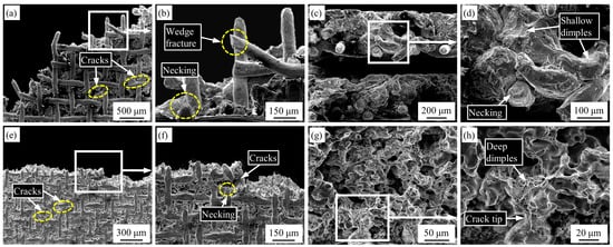
Figure 8.
Tensile fractography of the PTPs. (a–d) CPTP; (e–h) FPTP.
3.4. Load Capacity of the Aerostatic Bearings
Figure 9 shows the static load capacity and stiffness of the aerostatic bearing. With decreasing air film thickness, the load capacity increases gradually. When the air pressure was 0.5 MPa, and the air film thickness was 3.9 μm, the maximum load capacity of the aerostatic bearing with the CPTPs as the restrictor was 511 N (Figure 9a). When the air pressure was 0.5 MPa, and the film thickness was 2.4 μm, the maximum load capacity of the aerostatic bearing with the FPTPs as the restrictor was 465 N (Figure 9b). With increasing air pressure, the load capacity increased significantly. In particular, when the air pressure increased from 0.3 MPa to 0.5 MPa, the maximum load capacity increased from 312 N to 511 N, which is an improvement of 63.8%. While a reduced gas film thickness enhances load capacity, excessively thin films impose significant manufacturing and assembly challenges for aerostatic bearings, adversely impacting cost control and assembly efficiency. Conversely, excessive film thickness leads to a sharp increase in gas consumption and compromises operational stability. Consequently, maintaining a gas film thickness between 5 and 15 μm during practical operation offers optimal cost-effectiveness while improving bearing reliability. Therefore, the average stiffness calculated across the film thickness range of approximately 5 to 15 μm is adopted as the representative stiffness for aerostatic bearings.
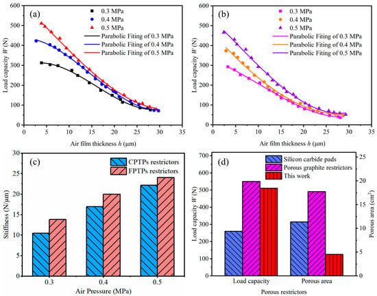
Figure 9.
Load capacity and stiffness of aerostatic bearings. (a) CPTPs as restrictors; (b) FPTPs as restrictors; (c) stiffness of aerostatic bearings; (d) comparison of load capacity and porous area.
Figure 9c shows the variation in stiffness for aerostatic bearings employing CPTP and FPTP restrictors as a function of supply pressure. When the supply pressure increased from 0.3 MPa to 0.5 MPa, the stiffness of the CPTP-restricted bearing rose from 11 N/μm to 22 N/μm, representing a 100% enhancement. Similarly, the FPTP-restricted bearing exhibited a stiffness increase from 14 N/μm to 24 N/μm, corresponding to a 71.4% improvement. These results demonstrate that supply pressure significantly influences gas film stiffness, with stiffness progressively increasing at higher pressures. This occurs because increasing the supply pressure directly raises the maximum pressure in the gas film, and the larger pressure difference and higher gas flow rate enhance the bearing load capacity [40]. Furthermore, higher-pressure gas supply enables rapid injection of sufficient gas through the restrictor, effectively suppressing film collapse. Given that stiffness is defined as the rate of pressure change relative to film thickness variation, the larger pressure fluctuations induced by load disturbances under high-pressure conditions consequently yield greater stiffness.
Interestingly, under identical supply pressures, the FPTP-restricted aerostatic bearing consistently exhibits higher stiffness than its CPTP-restricted counterpart. This indicates that among porous restrictors with comparable permeability, those featuring smaller average pore diameters enhance bearing stiffness. This enhancement arises because reduced orifice diameters in the restrictor cause a dramatic local velocity increase as gas flows through. Bernoulli’s principle dictates that elevated kinetic energy necessitates a corresponding reduction in static pressure, thereby amplifying the pressure differential. Consequently, the pressure gradient between the restrictor orifice and the gas film periphery steepens. When film thickness decreases, the pressure near the orifice rises precipitously, generating a stronger restoring force to counteract external loads, ultimately increasing bearing stiffness. Specifically, when the air film thickness was approximately 3 μm, the aerostatic bearing with a CPTP as the restrictor only needed approximately half of the porous area of a silicon carbide pad [41] or approximately a quarter of the porous graphite [42] area, and this led it to obtaining twice the load capacity of an aerostatic bearing with silicon carbide pad as the restrictor and was equivalent to that of an aerostatic bearing with porous graphite as the restrictor (Figure 9d). Notably, when the air film thickness was approximately 14 μm, the aerostatic bearing with a CPTP as the restrictor held a load capacity of 279 N, which was approximately five times that of the aerostatic bearing with the inherent orifice restrictors [43].
4. Conclusions
In summary, new types of PTPs were fabricated by using 304 stainless steel powder and wire mesh through composite rolling and vacuum sintering. These PTPs were applied as porous restrictors in aerostatic bearings. The main conclusions are as follows:
- (1)
- A novel wet process rolling method was proposed for coarse powder and wire mesh composite rolling. Reducing the rolling speed was useful to improve the rolling effect. Specifically, the phenomenon of uneven distribution of the powders can be eliminated by decreasing the roller speed to 1 r/min and supplemented by wet process rolling.
- (2)
- The PTPs with a larger average pore size and higher porosity exhibit enhanced permeability; however, the larger pore size significantly compromises mechanical strength. More complete metallurgical bonding and a smaller average pore size facilitate achieving higher mechanical performance in PTPs.
- (3)
- Benefiting from the micron-scale pore structure, good permeability, and excellent mechanical properties of PTPs, aerostatic bearings using PTPs as porous restrictors exhibit good load capacity and gas film stiffness. This demonstrates the potential application of PTPs in hydrostatic lubrication.
- (4)
- The aerostatic bearing with CPTPs restrictor shows slightly higher load capacity but lower gas film stiffness compared to the FPTPs restrictor. FPTPs are more suitable than CPTPs for aerostatic bearing restrictors.
Author Contributions
C.L.: Conceptualization, Writing—original draft, Investigation, Methodology, Data curation, Formal analysis, Funding acquisition. Z.Z.: Writing—review and editing, Resources, Supervision, Validation. All authors have read and agreed to the published version of the manuscript.
Funding
This research was funded by the Research Foundation for Talented Scholars Program of Foshan University (CGZ07422) and the Basic and Applied Basic Research Foundation of Guangdong (2023A1515110464).
Data Availability Statement
The original contributions presented in this study are included in the article. Further inquiries can be directed to the corresponding author.
Conflicts of Interest
The authors declare no conflicts of interest.
Correction Statement
This article has been republished with a minor correction to the Data Availability Statement. This change does not affect the scientific content of the article.
References
- Zhou, D.S.; Sun, H.F.; Guo, S.H.; Zhao, D.L.; Li, J.; Zhang, Y.H. Hydrogen storage properties of Mg-based alloys modified with metal-organic frameworks and carbon-based porous materials: A review and summary. Int. J. Hydrogen Energy 2024, 57, 1373–1388. [Google Scholar] [CrossRef]
- Wang, H.; Shi, H.; Lu, H.; Wang, C.; Li, H.L.; Yao, L.; Yu, A.A.; Liu, M.T.; Zuo, H.M.; Ruan, F.T.; et al. From wasted nonwoven fabrics to conductive flexible substrates, composited with electrospun porous carbon nanofibers for supercapacitor electrodes and electromagnetic interference shielding materials. Diamond Relat. Mater. 2025, 155, 112280. [Google Scholar] [CrossRef]
- Yadav, P.K.; Srivastava, P. Impact of porous material and slip condition on the MHD flow of immiscible Couple stress-Newtonian fluids through an inclined channel: Head loss and pressure difference. Chin. J. Phys. 2024, 89, 1198–1221. [Google Scholar] [CrossRef]
- Gao, Q.; Chen, W.; Lu, L.; Huo, D.; Cheng, K. Aerostatic bearings design and analysis with the application to precision engineering: State-of-the-art and future perspectives. Tribol. Int. 2019, 135, 1–17. [Google Scholar] [CrossRef]
- Wang, C.; Cheng, K.; Rakowski, R.; Soulard, J. An experimental investigation on ultra-precision instrumented smart aerostatic bearing spindle applied to high speed micro-drilling. J. Manuf. Process. 2018, 31, 324–335. [Google Scholar] [CrossRef]
- Belforte, G.; Colombo, F.; Raparelli, T.; Trivella, A.; Viktorov, V. Experimental analysis of air pads with micro holes. Tribol. Trans. 2013, 56, 169–177. [Google Scholar] [CrossRef]
- Fan, G.Z.; Li, Y.H.; Li, Y.H.; Zang, L.B.; Zhao, M.; Li, Z.X.; Yu, H.C.; Xu, J.L.; Liang, H.F.; Zhang, G.Q.; et al. Research on Design and Optimization of Micro-Hole Aerostatic Bearing in Vacuum Environment. Lubricants 2024, 12, 224. [Google Scholar] [CrossRef]
- Li, W.J.; Wang, S.J.; Feng, K. Numerical and experimental study on the effect of surface damages on the performances of porous aerostatic bearings. Tribol. Int. 2022, 175, 107791. [Google Scholar] [CrossRef]
- Zhang, P.; Zha, J. Dynamic accuracy model of porous journal air bearing considering rotational speed. Tribol. Int. 2021, 161, 107064. [Google Scholar] [CrossRef]
- Zhou, D.; Xiong, Y.; Yuan, H.; Luo, G.; Zhang, J.; Shen, Q.; Zhang, L. Synthesis and compressive behaviors of PMMA microporous foam with multi-layer cell structure. Compos. Part B Eng. 2019, 165, 272–278. [Google Scholar] [CrossRef]
- Wu, F.; Liu, Z.; Xiu, T.; Zhu, B.; Khan, I.; Liu, P.; Zhang, Q.; Zhang, B. Fabrication of ultralight helical porous carbon fibers with CNTs-confined Ni nanoparticles for enhanced microwave absorption. Compos. Part B Eng. 2021, 215, 108814. [Google Scholar] [CrossRef]
- Zhang, B.; Pei, X.; Song, P.; Sun, H.; Li, H.; Fan, Y.; Jiang, Q.; Zhou, C.; Zhang, X. Porous bioceramics produced by inkjet 3D printing: Effect of printing ink formulation on the ceramic macro and micro porous architectures control. Compos. Part B Eng. 2018, 155, 112–121. [Google Scholar] [CrossRef]
- Cheng, J.B.; Zhao, H.B.; Cao, M.; Li, M.E.; Zhang, A.N.; Li, S.L.; Wang, Y.Z. Banana Leaflike C-Doped MoS2 Aerogels toward Excellent Microwave Absorption Performance. ACS Appl. Mater. Interfaces 2020, 12, 26301–26312. [Google Scholar] [CrossRef]
- Zhang, C.; Gong, J.; Li, H.; Zhang, J. Fiber-based flexible composite with dual-gradient structure for sound insulation. Compos. Part B Eng. 2020, 198, 108166. [Google Scholar] [CrossRef]
- Huang, S.F.; Hu, Z.H.; Chen, Z.X.; Yang, D.Y.; Huang, W.L.; Zhang, B. An Experimental Study on the Thermal Performance of a Heat Sink Filled with Porous Aluminum Skeleton/Paraffin Composite Phase Change Material. Materials 2024, 17, 4332. [Google Scholar] [CrossRef] [PubMed]
- Santhosh, U.; Ahmad, J.; Ojard, G.; Smyth, I.; Gowayed, Y.; Jefferson, G. Effect of porosity on the nonlinear and time-dependent behavior of Ceramic Matrix Composites. Compos. Part. B Eng. 2020, 184, 107658. [Google Scholar] [CrossRef]
- Zhu, Y.; Lin, G.; Khonsari, M.M.; Zhang, J.; Yang, H. Material characterization and lubricating behaviors of porous stainless steel fabricated by selective laser melting. J. Mater. Process Technol. 2018, 262, 41–52. [Google Scholar] [CrossRef]
- Roque, R.; Barbosa, G.F.; Guastaldi, A.C. Design and 3D bioprinting of interconnected porous scaffolds for bone regeneration. An additive manufacturing approach. J. Manuf. Process 2021, 64, 655–663. [Google Scholar] [CrossRef]
- Tang, H.; Weng, C.; Tang, Y.; Li, H.; Xu, T.; Fu, T. Thermal performance enhancement of an ultra-thin flattened heat pipe with multiple wick structure. Appl. Therm. Eng. 2021, 183, 116203. [Google Scholar] [CrossRef]
- Xie, C.; Wu, S.; Yu, Y.; Zhang, H.; Hu, Y.; Zhang, M.; Wang, G. Defect-correlated fatigue resistance of additively manufactured Al-Mg4.5Mn alloy with in situ micro-rolling. J. Mater. Process Technol. 2021, 291, 117039. [Google Scholar] [CrossRef]
- Li, C.; Zhou, Z. Production and tensile behavior of novel powder wire mesh composite porous plates. Adv. Eng. Mater. 2021, 23, 2100585. [Google Scholar] [CrossRef]
- Tang, Y.; Zhou, W.; Pan, M.; Chen, H.; Liu, W.; Yu, H. Porous copper fiber sintered felts: An innovative catalyst support of methanol steam reformer for hydrogen production. Int. J. Hydrogen Energy 2008, 33, 2950–2956. [Google Scholar] [CrossRef]
- Yu, J.; Hu, X.; Huang, Y. A modification of the bubble-point method to determine the pore-mouth size distribution of porous materials. Sep. Purif. Technol. 2010, 70, 314–319. [Google Scholar] [CrossRef]
- Varol, Y. Natural convection for hot materials confined within two entrapped porous trapezoidal cavities. Int. Commun. Heat. Mass. Transf. 2012, 39, 282–290. [Google Scholar] [CrossRef]
- Biasetto, L.; Innocentini, M.; Chacon, W.; Corradetti, S.; Carturan, S.; Colombo, P.; Andrighetto, A. Gas permeability of lanthanum oxycarbide targets for the SPES project. J. Nucl. Mater. 2013, 440, 70–80. [Google Scholar] [CrossRef]
- Li, C.; Zhou, Z. Air permeability and tensile properties of novel micron-scale gradient porous plates fabricated by rolling and vacuum sintering. Powder Technol. 2022, 399, 117205. [Google Scholar] [CrossRef]
- Dukhan, N.; Bağcı, Ö.; Özdemir, M. Experimental flow in various porous media and reconciliation of Forchheimer and Ergun relations. Exp. Therm. Fluid Sci. 2014, 57, 425–433. [Google Scholar] [CrossRef]
- Deng, H.; Huang, Y.; Wu, S.; Yang, Y. Binder jetting additive manufacturing: Three-dimensional simulation of micro-meter droplet impact and penetration into powder bed. J. Manuf. Process 2022, 74, 365–373. [Google Scholar] [CrossRef]
- Chen, X.B.; Li, Y.C.; Hodgson, P.D.; Wen, C. The importance of particle size in porous titanium and nonporous counterparts for surface energy and its impact on apatite formation. Acta Biomater. 2009, 5, 2290–2302. [Google Scholar] [CrossRef]
- Vogiatzis, C.A.; Skolianos, S.M. On the sintering mechanisms and microstructure of aluminium–ceramic cenospheres syntactic foams produced by powder metallurgy route. Compos. Part A Appl. Sci. Manuf. 2016, 82, 8–19. [Google Scholar] [CrossRef]
- He, G.; Liu, P.; Tan, Q. Porous titanium materials with entangled wire structure for load-bearing biomedical applications. J. Mech. Behav. Biomed. Mater. 2012, 5, 16–31. [Google Scholar] [CrossRef]
- Chaudhari, G.P.; Acoff, V. Cold roll bonding of multi-layered bi-metal laminate composites. Compos. Sci. Technol. 2009, 69, 1667–1675. [Google Scholar] [CrossRef]
- Jones, K.L.; Laudone, G.M.; Matthews, G.P. A multi-technique experimental and modelling study of the porous structure of IG-110 and IG-430 nuclear graphite. Carbon 2018, 128, 1–11. [Google Scholar] [CrossRef]
- Panzera, T.H.; Rubio, J.C.; Bowen, C.R.; Walker, P.J. Microstructural design of materials for aerostatic bearings. Cem. Concr. Compos. 2008, 30, 649–660. [Google Scholar] [CrossRef]
- Li, Y.; Yang, X.; Liu, D.; Chen, J.; Zhang, D.; Wu, Z. Permeability of the porous Al2O3 ceramic with bimodal pore size distribution. Ceram. Int. 2019, 45, 5952–5957. [Google Scholar] [CrossRef]
- Dele-Afolabi, T.T.; Azmah Hanim, M.A.; Ojo-Kupoluyi, O.J.; Calin, R.; Zuhri, M.Y.M. Tailored pore structures and mechanical properties of porous alumina ceramics prepared with corn cob pore-forming agent. Int. J. Appl. Ceram. Technol. 2020, 18, 244–252. [Google Scholar] [CrossRef]
- Scherm, F.; Völkl, R.; Neubrand, A.; Bosbach, F.; Glatzel, U. Mechanical characterisation of interpenetrating network metal–ceramic composites. Mater. Sci. Eng. A 2010, 527, 1260–1265. [Google Scholar] [CrossRef]
- Lee, K.; Son, C.-Y.; Lee, S.-B.; Lee, S.-K.; Lee, S. Direct observation of microfracture process in metallic-continuous-fiber-reinforced amorphous matrix composites fabricated by liquid pressing process. Mater. Sci. Eng. A 2010, 527, 941–946. [Google Scholar] [CrossRef]
- Zhou, Y.; Wang, Q.; Han, X.-L.; Sun, D.-L. Fabrication and properties of continuous unidirectional Mo fiber reinforced TiAl composites by slurry casting and vacuum hot pressing. Compos. Sci. Technol. 2013, 83, 72–78. [Google Scholar] [CrossRef]
- Wu, Y.K.; Li, C.L.; Li, J.; Du, J.J. Lubrication mechanism and characteristics of aerostatic bearing with close-spaced micro holes. Tribol. Int. 2024, 192, 109278. [Google Scholar] [CrossRef]
- Schenk, C.; Buschmann, S.; Risse, S.; Eberhardt, R.; Tünnermann, A. Comparison between flat aerostatic gas-bearing pads with orifice and porous feedings at high-vacuum conditions. Precis. Eng. J. Int. Soc. Precis. Eng. Nanotechnol. 2008, 32, 319–328. [Google Scholar] [CrossRef]
- Luong, T.S.; Potze, W.; Post, J.B.; van Ostayen, R.A.J.; van Beek, A. Numerical and experimental analysis of aerostatic thrust bearings with porous restrictors. Tribol. Int. 2004, 37, 825–832. [Google Scholar] [CrossRef]
- Zhang, J.; Zou, D.; Ta, N.; Rao, Z. Numerical research of pressure depression in aerostatic thrust bearing with inherent orifice. Tribol. Int. 2018, 123, 385–396. [Google Scholar] [CrossRef]
Disclaimer/Publisher’s Note: The statements, opinions and data contained in all publications are solely those of the individual author(s) and contributor(s) and not of MDPI and/or the editor(s). MDPI and/or the editor(s) disclaim responsibility for any injury to people or property resulting from any ideas, methods, instructions or products referred to in the content. |
© 2025 by the authors. Licensee MDPI, Basel, Switzerland. This article is an open access article distributed under the terms and conditions of the Creative Commons Attribution (CC BY) license (https://creativecommons.org/licenses/by/4.0/).